Girth Gear Technical Manual
Girth Gear Technical Manual
Girth Gear Technical Manual

You also want an ePaper? Increase the reach of your titles
YUMPU automatically turns print PDFs into web optimized ePapers that Google loves.
<strong>Girth</strong> gears are manufactured from segments.<br />
A girth gear is divided into 8–16 segments,<br />
which are joined by bolts. The segment length<br />
typically varies between 0.8–1.6 m. Short segments<br />
enable the use of small versatile and<br />
accurate machines. Due to this, optimal and<br />
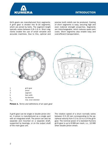
1 girth gear<br />
pinion<br />
3 segment<br />
b face width<br />
d tip diameter<br />
a<br />
d max. drum diameter<br />
max<br />
Picture 1. Terms and definitions of an open gear<br />
A girth gear can be single or double pinion driven.<br />
A pinion is manufactured as a single part<br />
with an integrated shaft. The pinion can also be<br />
separate and mounted on a separate shaft,<br />
supported by bearings, or on the output shaft<br />
of the main gear unit.<br />
INTRODUCTION<br />
precise tooth reliefs can be produced. Casting<br />
of short segments is easy, securing high and<br />
even material strength properties. Segments<br />
are interchangeable, which reduces spare part<br />
costs. Short segments also enable easy and<br />
cost-efficient transportation.<br />
The rotation speed of a drum normally varies<br />
between 0.5– 0 rpm corresponding to the peripheral<br />
velocity from 0.3 to 10 m/s of the girth<br />
gear. The nominal power of a standard Kumera<br />
girth gear is up to 8 MW per mesh, i.e., 16 MW<br />
when double pinion driven.