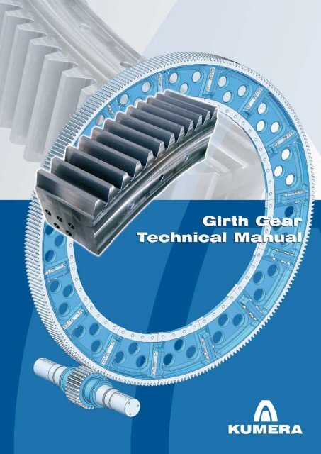
Girth Gear Technical Manual
Girth Gear Technical Manual
Girth Gear Technical Manual

You also want an ePaper? Increase the reach of your titles
YUMPU automatically turns print PDFs into web optimized ePapers that Google loves.
<strong>Girth</strong> gears are manufactured from segments.<br />
A girth gear is divided into 8–16 segments,<br />
which are joined by bolts. The segment length<br />
typically varies between 0.8–1.6 m. Short segments<br />
enable the use of small versatile and<br />
accurate machines. Due to this, optimal and<br />
1 girth gear<br />
pinion<br />
3 segment<br />
b face width<br />
d tip diameter<br />
a<br />
d max. drum diameter<br />
max<br />
Picture 1. Terms and definitions of an open gear<br />
A girth gear can be single or double pinion driven.<br />
A pinion is manufactured as a single part<br />
with an integrated shaft. The pinion can also be<br />
separate and mounted on a separate shaft,<br />
supported by bearings, or on the output shaft<br />
of the main gear unit.<br />
INTRODUCTION<br />
precise tooth reliefs can be produced. Casting<br />
of short segments is easy, securing high and<br />
even material strength properties. Segments<br />
are interchangeable, which reduces spare part<br />
costs. Short segments also enable easy and<br />
cost-efficient transportation.<br />
The rotation speed of a drum normally varies<br />
between 0.5– 0 rpm corresponding to the peripheral<br />
velocity from 0.3 to 10 m/s of the girth<br />
gear. The nominal power of a standard Kumera<br />
girth gear is up to 8 MW per mesh, i.e., 16 MW<br />
when double pinion driven.
GEAR TECHNOLOGY<br />
The manufacturing method of girth gears enables<br />
wide possibilities for geometry modifications.<br />
Typically, the tooth geometry is according<br />
to Table 1.<br />
Table 1. Typical geometry of a girth gear<br />
Pinion flanks are modified by tip, root and end<br />
reliefs. The modifications compensate the deflection<br />
of the drive system, thus high contact<br />
pressure on the tooth edges can be avoided.<br />
Min. Max. Standard<br />
Module 0 40 7<br />
Pressure angle, [°] 4<br />
Helix angle, [°] 0 45 0<br />
Number of teeth:<br />
– <strong>Girth</strong> gear 100 300<br />
– Pinion 18 30<br />
Face width, [mm] 100 500<br />
Reference diameter [mm] 000 no limitation<br />
Quality ISO AGMA<br />
<strong>Girth</strong> <strong>Gear</strong> 8–10 9–7<br />
Pinion 7 10<br />
The tooth load carrying capacity can be calculated<br />
according to the following standards:<br />
– ANSI/AGMA 6004-F88 <strong>Gear</strong> Power Rating<br />
for Cylindrical Grinding Mills, Kilns, Coolers<br />
and Dryers<br />
– ISO 6336 Calculation of load capacity of<br />
spur and helical gears<br />
– DIN 3990 Calculation of load capacity of cylindrical<br />
gears<br />
3<br />
�
Table 2. Minimum service factors according to AGMA 6004 (* < 1.5 rpm)<br />
4<br />
GEAR TECHNOLOGY<br />
Application Durability, C SF Strength, K SF<br />
Coolers 1.00 * 1.5 *<br />
Dryers 1.00 * 1.5 *<br />
Kilns 1.00 * 1.75*<br />
Grinding Mills:<br />
Ball 1.5 . 5<br />
Autogenous 1.5 .4<br />
Rod 1.5 .5<br />
A girth gear can be assembled to a drum with a flanged connection or with spring elements.<br />
Picture 2. The FE-method is utilized for deformation and stress calculation of a whole girth gear<br />
including the strength calculation of the fixing structure
MATERIALS<br />
A common material for girth gears has been<br />
spheroidal graphite cast iron EN 1563 – GJS<br />
800- . Nowadays, austempered ductile iron,<br />
ADI, EN 1564 – GJS1000-5 is more and more<br />
used. Its principal attribute is its high strengthto-weight<br />
ratio.<br />
In the past, pinions were often made from<br />
through-hardened steel. At present, the stand-<br />
Table 3. Material properties<br />
Material Hardness<br />
<strong>Girth</strong> gear<br />
Tensile<br />
strength<br />
[N/mm 2 ]<br />
ard material for Kumera pinions is case-hardened<br />
17CrNiMo7-6. Teeth are ground after heat<br />
treatment. The pinions have a substantially improved<br />
load-carrying capacity, better quality of<br />
teeth, and good surface quality of tooth flanks,<br />
resulting in better operational reliability. Pinions<br />
are also less wide with the same nominal output<br />
torque, which improves the load distribution<br />
across the face width.<br />
Allowable<br />
contact<br />
stress<br />
[N/mm 2 ]<br />
Allowable<br />
bending<br />
stress<br />
[N/mm 2 ]<br />
Young’s<br />
modulus<br />
[kN/mm 2 ]<br />
EN 1563 – GJS 800- 80–3 0 HB 800 700 48 185<br />
EN 1564 – GJS 1000-5 (ADI) 300–360 HB 1000 1 00 3 0 159<br />
Pinion<br />
EN 10084 – 17CrNiMo7-6 58–6 HRC 1 00 1500 500 06<br />
5<br />
�
The standardization of the ADI material has<br />
proceeded in recent years, which facilitates its<br />
use. The standards ASTM A897/A897M-06,<br />
EN 1564:1997, and ISO 17804: 005 outline<br />
the ADI grades varying in mechanical properties.<br />
The information sheet AGMA 939-A07<br />
Austempered Ductile Iron for <strong>Gear</strong>s covers the<br />
areas of designing, purchasing specifying and<br />
verifying the ADI material, in particular for applications<br />
in gears and power train components.<br />
ADI is produced by heat treating ductile iron,<br />
using the austempering process. Austempering<br />
is a specialized, isothermal heat treatment.<br />
When compared to conventional ductile iron,<br />
ADI can have over twice the strength for a given<br />
level of ductility. ADI can have a fatigue strength<br />
Table 4. Properties of different ADI-grades<br />
6<br />
MATERIALS, ADI<br />
comparable to that of cast and forged steels.<br />
ADI’s strength can be greatly enhanced by subsequent<br />
grinding, fillet rolling or shot peening.<br />
The ausferrite matrix in ADI undergoes a strain<br />
transformation hardening when exposed to a<br />
high normal force. This same strain transformation<br />
hardening is what gives ADI a better<br />
wear resistance than the bulk hardness would<br />
indicate. Other attributes of ADI material include<br />
good noise dampening, fracture toughness,<br />
low temperature properties, and reasonable<br />
stiffness. ADI has a 0 % lower Young’s<br />
Modulus than steel. In gears, this results in a<br />
larger contact area for a given input load. In<br />
some cases, this has been shown to reduce<br />
contact stress and noise.<br />
ADI 750 900 1050 1200 1400 1600<br />
Herzian resistance Modest Moderate Fair Good Good Very good<br />
Bending resistance Very good Good Good Fair Modest Poor<br />
Machinability Very good Good Poor<br />
Shot peening Good Good<br />
Load capacity Moderate High Very high<br />
Exceeds<br />
ductile iron<br />
Competes<br />
with<br />
throughhardening<br />
Exceeds<br />
throughhardening<br />
Competes<br />
with<br />
nitrided<br />
steel<br />
Exceeds<br />
flame<br />
hardening<br />
Competes<br />
with case<br />
hardening
LUBRICATION<br />
The most common type of operational lubrication<br />
is automatic interval spray lubrication,<br />
where the applied lubrication volume is controlled<br />
by the spray as well as pause times.<br />
If a drum is rotated by a girth gear before the<br />
lubrication system is taken into operation, priming<br />
lubrication is recommended. A priming lubricant<br />
prevents damage during initial operation.<br />
The priming lubricant is applied once to all tooth<br />
flanks by a brush or spatula.<br />
Based on experience, it can be stated that a<br />
girth gear’s rolling strength and scuffing load<br />
Table 5. Lubricant consumption for running-in and operational lubrication<br />
Application<br />
capacity are improved by reducing flank roughness<br />
and increasing the effective contact ratio.<br />
During the running-in period, limited wear is intentionally<br />
produced at the tooth flanks, which<br />
improves the tooth surface roughness and further<br />
increases the load contact area.<br />
During the running-in, increased lubricant<br />
throughput is necessary to flush out the initial<br />
metal wear generated through the removal of<br />
the surface peaks and high spots during the<br />
first stages of the process. An average runningin<br />
time is 300 hours.<br />
Consumption (g/cm/op. hour.)<br />
Running-in Operational<br />
Rotary drum drives (coolers) 4 1.0 – 1.5<br />
Single pinion kiln drives 5 1.5 – .0<br />
Single pinion mill or kiln drives 6 .0 – .5<br />
Single pinion mill drives and double pinion kiln<br />
drives of large dimensions<br />
7 .5 – 3.0<br />
Double pinion mill drives 8 3.0 – 3.5<br />
7<br />
�
Selection<br />
Determine the minimum diameter of the girth gear (table 9)<br />
d drum < d max<br />
Determine the required girth gear selection torque<br />
T drum * K A = T D<br />
If the required drum torque is not known, it can be calculated from motor power<br />
T drum = 9,550 * P 1 * η / n<br />
Select ratio, face width, and material in accordance with the equation below<br />
T D < T * f w * f d<br />
Selection example<br />
Application: Kiln<br />
Outer diameter of drum: d drum = 4500 mm<br />
Input power of drum: P 1 = * 00 kW (double pinion)<br />
Rotation speed of drum: n = 1.4 rpm,<br />
Main gear unit: three-stage<br />
Smallest possible girth gear: d drum < d max , d max = 4600 mm<br />
Application factor: K A = 1.75<br />
Drive number factor: f d = 1.95<br />
Efficiency of drive: η = 0.96<br />
8<br />
SELECTION<br />
Drum torque: T drum = 9,550 * ( * 00) * 0.96 / 1.4 = 619<br />
kNm<br />
Selection torque of drum: T D = 619 * 1.75 = 4583 kNm<br />
Select girth gear from table 7: T D < T * f w * f d, 4583 < 050 * 1.95 * 1.19<br />
Selected girth gear:<br />
Material: GJS-1000-5 (ADI)<br />
Tip diameter of drum, d a : 5346 mm<br />
Number of teeth of girth gear, z : 196<br />
Number of teeth of pinion, z 1 : 18<br />
<strong>Girth</strong> gear ratio, i: 10.89:1<br />
Face width of girth gear, b: 380 mm
SELECTION<br />
Symbols<br />
ddrum dmax Tdrum KA T D<br />
T<br />
outer diameter of drum, [mm]<br />
max. diameter of drum, [mm]<br />
drum torque, [kNm]<br />
selection factor, (table 6)<br />
girth gear selection torque, [kNm]<br />
nominal torque of girth gear, [kNm] (table 10)<br />
P1 n<br />
input power of drum drive, [kW]<br />
drum speed, [rpm]<br />
z1 z<br />
number of teeth of pinion<br />
number of teeth of girth gear<br />
i open gear ratio<br />
fw fd η<br />
face width factor, (table 7)<br />
drive number factor, (8)<br />
efficiency, (table 9)<br />
Table 6. Selection factor, K A<br />
Application Selection factor, K A<br />
Coolers 1.5<br />
Dryers 1.5<br />
Kilns 1.75<br />
Grinding Mills:<br />
Ball . 5<br />
Autogenous .4<br />
Rod .5<br />
Table 7. Face width factor, f w<br />
B, [mm] 100 140 180 0 60 300 340 380 4 0 460 500<br />
Factor 0.38 0.5 0.65 0.78 0.89 1.00 1.10 1.19 1. 7 1.34 1.40<br />
Table 8. Drive number factor, f d<br />
Single drive 1<br />
Double drive 1.95<br />
Table 9. Approximated efficiency, η<br />
Number of stages including girth gear 1 3 4 5<br />
efficiency 0.99 0.98 0.97 0.96 0.95<br />
9<br />
�
Table 10. Selection table for girth gear<br />
Geometrical data GJS-800- GJS-1000-5 (ADI)<br />
d max,<br />
[mm]<br />
10<br />
d a,<br />
[mm]<br />
z z 1 i<br />
n [rpm] n [rpm]<br />
SELECTION<br />
1 5 10 0 10 1 5 10 0 10<br />
P [kW] T2[kNm] P [kW] T2[kNm]<br />
450 3078 11 18 6. 34 180 370 765 355 1 5 635 1 50 450 1 00<br />
4 4.67 47 55 535 1100 510 130 645 1 50 500 1 00<br />
30 3.73 63 335 705 1450 675 130 650 1 50 500 1 00<br />
850 3456 1 6 18 7.00 39 05 4 5 890 405 140 710 1400 750 1300<br />
4 5. 5 54 95 6 5 1300 600 145 7 0 1400 800 1350<br />
30 4. 0 73 395 830 1700 795 145 730 1400 800 1350<br />
3 00 3834 140 18 7.78 44 35 480 1000 460 155 785 1550 3050 1450<br />
4 5.83 6 340 7 0 1500 690 160 800 1550 3050 1500<br />
30 4.67 84 455 955 1950 915 160 805 1550 3050 1500<br />
3600 4 1 154 18 8.56 50 60 535 1050 510 170 865 1700 3350 1600<br />
4 6.4 66 360 765 1600 730 175 875 1700 3350 1650<br />
30 5.13 90 490 1000 150 985 175 885 1700 3350 1650<br />
3850 4590 168 18 9.33 55 90 595 1 00 565 185 940 1850 3600 1750<br />
4 7.00 73 405 855 1800 8 0 190 950 1850 3600 1750<br />
30 5.60 100 550 1150 400 1100 195 960 1850 3600 1800<br />
4 50 4968 18 18 10.11 60 315 650 1300 6 0 05 1000 000 3900 1900<br />
4 7.58 81 445 950 1900 905 05 1000 000 3900 1900<br />
30 6.07 110 610 1 50 600 1 00 10 1000 000 3900 1900<br />
4600 5346 196 18 10.89 65 345 705 1400 675 0 1050 150 4150 050<br />
4 8.17 89 490 1000 100 995 0 1100 150 4150 050<br />
30 6.53 1 0 670 1400 850 1300 5 1100 150 4150 050<br />
5000 57 4 10 18 11.67 71 370 765 1500 730 35 1150 50 4450 150<br />
4 8.75 96 535 1100 300 1050 35 1150 300 4450 00<br />
30 7.00 130 730 1500 3100 1450 40 1150 300 4400 00<br />
5400 610 4 18 1 .44 76 400 8 0 1600 780 50 1 00 400 4700 300<br />
4 9.33 100 550 1150 300 1100 55 1 50 450 4650 300<br />
30 7.47 135 760 1600 3150 1500 55 1 50 450 4650 350<br />
5650 6480 38 18 13. 81 4 5 875 1700 835 55 1 50 500 4800 350<br />
4 9.9 105 590 1 50 500 1 00 60 1 50 500 4800 400<br />
30 7.93 145 8 0 1700 3150 1650 65 1300 500 4750 400<br />
6100 6939 55 18 14.17 88 460 945 1850 900 75 1350 650 5150 550<br />
4 10.63 115 645 1350 700 1300 80 1350 650 5100 550<br />
30 8.50 160 895 1850 3350 1750 80 1350 650 5000 550<br />
6500 7344 70 18 15.00 93 490 1000 1950 960 90 1400 800 5400 700<br />
4 11. 5 1 5 690 1450 900 1400 95 1450 800 5350 700<br />
30 9.00 170 960 1950 3500 1900 300 1450 800 5 50 700<br />
6900 7749 85 18 15.83 99 5 0 1050 100 1000 305 1500 950 5650 800<br />
4 11.88 130 740 1550 3100 1450 310 1500 950 5600 800<br />
30 9.50 185 1000 050 3650 1950 315 1500 950 5500 800<br />
7300 81 7 99 18 16.61 100 550 1100 150 1050 3 0 1550 3100 5900 950<br />
4 1 .46 140 745 1550 3050 1500 3 5 1600 3100 5800 950<br />
30 9.97 185 1000 050 3550 000 330 1600 3050 5700 950
INSTALLATION, MAINTENANCE<br />
The allowable radial and axial runout as well<br />
the required tooth clearance can be found in<br />
the installation instructions. If necessary, all<br />
necessary support and adjustment tools for installation<br />
can be delivered as an option.<br />
The maintenance inspection typically covers assessment<br />
of the load carrying pattern, checking<br />
of the lubrication system, vibration meas-<br />
urement of the pinion bearings, measurement<br />
of the temperature profile across the tooth<br />
width, and documentation of the condition of<br />
the flanks. Written documentation includes<br />
photos of tooth flanks, which facilitate detection<br />
of changes in the girth gear condition by<br />
comparing and analyzing earlier inspection documents.<br />
Picture 3. Infrared photo of a running girth gear, load carrying pattern photo<br />
11<br />
�
COMPLETE DRIVE PACKAGE<br />
<strong>Girth</strong> gear is typically part of drum drive<br />
delivery which consist steel foundation,<br />
main drive, pinion, girth gear, fixing<br />
elements and girth gear cover. Depending<br />
on the application emergency drives,<br />
indexing drives, couplings, clutches and<br />
brakes can be also part of the delivery<br />
scope.<br />
KUMERA DRIVES OY<br />
FI-11100 Riihimäki<br />
FINLAND<br />
Tel.: +358 0 755 4 00<br />
Fax: +358 0 755 4 0<br />
E-mail: drives@kumera.com<br />
www.kumera.com<br />
Vammalan Kirjapaino Oy 007