And how to build one - The Guitar Effects Oriented Web Page
And how to build one - The Guitar Effects Oriented Web Page
And how to build one - The Guitar Effects Oriented Web Page

Create successful ePaper yourself
Turn your PDF publications into a flip-book with our unique Google optimized e-Paper software.
About GEO Fex<br />
GEO Fex<br />
GEO Fex DIY effects packages are designed with the musical effects<br />
experimenter in mind. GEO Fex offers the musical tinkerer the ability <strong>to</strong> work<br />
with and modify <strong>to</strong> his or her own liking circuits that accurately reproduce the<br />
technology of vintage effects.<br />
Austin Treble Blaster<br />
GEO Fex packages reflect over two decades of research in<strong>to</strong> effects technology<br />
and production techniques. <strong>The</strong> goal of the GEO Fex package is <strong>to</strong> make the<br />
sounds and circuits of a number of vintage effects available at a cost that is<br />
reasonable for the musical electronics enthusiast even when the enthusiast is<br />
making only <strong>one</strong> unit for himself.<br />
A Workalike of the Original<br />
Dallas Rangemaster<br />
Build a cl<strong>one</strong> of the classic effect<br />
As such, the emphasis is on achieving near-professional results in an at-home<br />
or in-garage setting. Modern <strong>to</strong>ner-transfer technology allows the production of<br />
near-professional quality printed circuit boards <strong>one</strong> at a time by experimenters.<br />
Modern electronics mail-order suppliers can provide parts that were once very<br />
hard <strong>to</strong> find for the individual. <strong>The</strong> only missing part here is information - what<br />
was the circuit of a given vintage effect, and what special steps are needed <strong>to</strong><br />
get the effect working right. This information is what GEO Fex all about.<br />
GEO Fex packages reflect as closely as is known the original circuit of the<br />
vintage effect they are taken from. In some packages, the circuit was changed<br />
from the original in ways that make the GEO Fex package a better fit for<br />
modern musical effects practice - addition of true bypass switching, switch pop<br />
suppression resis<strong>to</strong>rs, and so forth. No changes are made that change the sound,<br />
which is, after all, the reason we do this.<br />
GEO Fex packages have all been built and tested before you get them. <strong>The</strong>y DO<br />
work, and they DO sound like the originals.<br />
Copyright 1998 R.G. Keen. All rights reserved. No copies of any portion of<br />
this document may be made by any means whatsoever without explicit<br />
written permission from the author.<br />
In some cases, detective work was needed <strong>to</strong> make the circuitry in GEO Fex<br />
packages available. Some of the vintage effects offered are so rare that n<strong>one</strong><br />
could be found for research, or the companies that provided them are no longer<br />
in existence. This meant quite a search for the underlying technical information<br />
in many cases.<br />
"Dallas Rangemaster" is a trademark owned by whomever acquired it from the<br />
original company. GEO Fex does not own the trademark, it remains property<br />
of the owner(s), and is used here for reference and comparison only. <strong>The</strong>re are<br />
three pedals marketed as workalikes for the Dallas Rangemaster, the “Range<br />
1”, the “Range 2” and the “Rangemaster 65”. Those terms are trademarks,<br />
property of the respective owners, and should not be confused with the unit<br />
described here.<br />
GEO Fex packages refer <strong>to</strong> the original effect. This reference is for convenience<br />
in reference only, and does not imply that GEO Fex is in any way affiliated<br />
with the original maker, or the maker of any reissue effect, or the current owner<br />
of the trademark of the original effect. All trademarks are the property of their<br />
respective owners. GEO Fex artwork, packaging, layouts, and schematics are<br />
all new and original, and are not known or intended <strong>to</strong> infringe any copyright,<br />
trademark or patent.
Austin Treble Blaster Austin Treble Blaster<br />
Austin Treble Blaster, a Dallas Rangemaster Workalike<br />
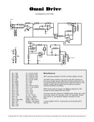
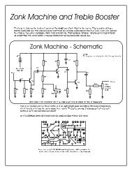
<strong>The</strong> collec<strong>to</strong>r resis<strong>to</strong>r is just the output level control pot, a 10K unit with an<br />
audio taper. <strong>The</strong> “hot” lug is tied <strong>to</strong> the collec<strong>to</strong>r of the transis<strong>to</strong>r, the “cold”<br />
<strong>The</strong> original Dallas Rangemaster has been little known in the USA, and under-<br />
lug tied <strong>to</strong> the battery supply, and the audio output taken from the wiper<br />
appreciated. Many guitarists have experimented for a long time trying <strong>to</strong><br />
through the 0.01uF capaci<strong>to</strong>r <strong>to</strong> the output switch. Some original Dallas<br />
emulate some sounds common in recordings from Europe, without notable<br />
Rangemasters used a 22K boost set pot, possibly as part of the tuning process <strong>to</strong><br />
success. It turns out that the Dallas Rangemaster may have been the secret<br />
adapt a lower gain transis<strong>to</strong>r <strong>to</strong> the circuit.<br />
weapon. Network research and personal email have indicated that the Dallas<br />
Rangemaster was a key item in the sound Eric Clatp<strong>to</strong>n achieved in the<br />
Bluesbreakers album, Rory Gallagher’s <strong>to</strong>ne, and later Brian May. In the US,<br />
Tony Iommi noted in an interview that he used <strong>one</strong> for his work on the first<br />
Black Sabbath album.<br />
What does this secret weapon do?<br />
First and foremost, it’s a treble booster. It provides gain of up <strong>to</strong> 24db at<br />
frequencies above about <strong>one</strong> <strong>to</strong> two kHz. It has about unity gain at the lowest<br />
normal guitar notes, and the gain about doubles with each octave. Since a<br />
doubling of level is a just-perceptible change in loudness, not a perceived<br />
doubling of loudness, this amounts <strong>to</strong> a fairly mild increase in level for higher<br />
notes, enough <strong>to</strong> make the guitar more “present”. It shares this characteristic<br />
with other treble booster effects. If that was all that happened, there wouldn’t<br />
be much excitement.<br />
However, the Dallas Rangemaster has some other tricks. As a result of the use<br />
of germanium devices and careful biasing, there is a subtle dis<strong>to</strong>rtion added, as<br />
well as a changeover <strong>to</strong> harder dis<strong>to</strong>rtion on loud notes, and the built-in ability<br />
<strong>to</strong> overdrive a tube amp input for some more serious dis<strong>to</strong>rtion. <strong>The</strong>se effects<br />
get more prominent as frequency goes up, so there is a very characteristic note<br />
added by the Dallas Rangemaster.<br />
So – <strong>how</strong> does it work?<br />
<strong>The</strong> Austin Treble Blaster uses the same circuit as the original Dallas<br />
Rangemaster, so the comments apply <strong>to</strong> both circuits.<br />
<strong>The</strong> original Dallas Rangemaster was intended for use only between a guitar<br />
and an amp, no other effects between them. As such, it did not use a “pull<br />
down” resis<strong>to</strong>r at either input or output, as the guitar pulled down the input cap<br />
leakage, and the (presumably tube) amp input grid leak resis<strong>to</strong>r pulled down<br />
<strong>The</strong> Dallas Rangemaster/ Austin Treble Blaster couldn’t be simpler. Referring<br />
<strong>to</strong> the original schematic, there is only <strong>one</strong> transis<strong>to</strong>r, biased by four resis<strong>to</strong>rs.<br />
<strong>The</strong> 470K/68K series resis<strong>to</strong>r string provides a bias voltage <strong>to</strong> the base of the<br />
device, helping <strong>to</strong> set the static current in the collec<strong>to</strong>r. Since germanium<br />
transis<strong>to</strong>rs are used, the collec<strong>to</strong>r-base leakage also “helps” set the bias point as<br />
well. <strong>The</strong> 4.7K resis<strong>to</strong>r, in conjunction with the input divider helps set and<br />
stabilize the bias point against drift and temperature variations. Its value and<br />
that of the nominal 68K base resis<strong>to</strong>r are key <strong>to</strong> setting the bias point, so the<br />
exact values of these resis<strong>to</strong>rs should be set upon testing with the actual<br />
transis<strong>to</strong>r <strong>to</strong> be used.
Austin Treble Blaster Austin Treble Blaster<br />
the output cap leakage, so there was no [clik] when it was switched. In modern<br />
current, but since electrons can now be absorbed by the now-positive grid, a<br />
setups, we cannot rely on those assumptions, so for my use I have added 2.2M<br />
grid current flows. <strong>The</strong> grid voltage, which controls the plate current, depends<br />
“pulldown” resis<strong>to</strong>rs at both ends for maximum flexibility. <strong>The</strong> pulldown<br />
on whether the impedance driving the grid has a low enough impedance <strong>to</strong><br />
resis<strong>to</strong>r have no audible effect, by actual test, other than keeping [cliks] from<br />
supply the grid current. A high impedance source will be unable <strong>to</strong> drive the<br />
happening. If you are a stickler for originality, you can simply leave these<br />
grid current, so the grid voltage will remain fixed at only slightly over zero<br />
resis<strong>to</strong>rs off. <strong>The</strong> pulldown resis<strong>to</strong>rs are a practical necessity for use in a<br />
volts, and the plate current will appear clipped for that part of the signal cycle<br />
modern context with true bypass, which the original did not have.<br />
where the grid is driven positive.<br />
This leads <strong>to</strong> the curious fact that a low impedance source driving a tube grid<br />
will have a less dis<strong>to</strong>rted and more softly dis<strong>to</strong>rted plate signal than will a<br />
higher impedance source.<br />
<strong>The</strong> Dallas Rangemaster has an output impedance no higher than the output<br />
pot resistance of 10K, and lower than that over most of the pot travel. This is<br />
substantially lower than the equivalent forward biased grid resistance of a<br />
12AX7, so it can drive an input grid somewhat positive. <strong>The</strong> resulting<br />
dis<strong>to</strong>rtion is smoother than a high impedance source would be. Note that amps<br />
that have series 68K resis<strong>to</strong>rs for “mixing” two inputs may not s<strong>how</strong> the full<br />
benefit of this effect.<br />
Another quirk of the original is that there is a DC voltage across the volume<br />
control, which also serves as the collec<strong>to</strong>r load resis<strong>to</strong>r. This means that it will<br />
inevitably scratch and crackle whenever the control is moved even if you use<br />
high-collar conductive plastic pots. This was OK in the time of the original<br />
unit, as the designer assumed that a player would set up this thing and leave it,<br />
not twiddling the control during a number. <strong>The</strong>re are ways <strong>to</strong> “correct” this, but<br />
they complicate the design unduly, so I have chosen <strong>to</strong> leave them out, going<br />
with the original circuit. It will crackle when you twist the “boost set” control.<br />
Digging deeper<br />
In terms of frequency response, I ran some measurements on the original unit. I<br />
had <strong>to</strong> measure the gain with an input of 10mv peak <strong>to</strong> keep the signal<br />
undis<strong>to</strong>rted. <strong>The</strong> gain versus frequency is as follows:<br />
<strong>The</strong> magic in the effect is all buried in the details of the biasing, the transis<strong>to</strong>r<br />
characteristics, and what it does <strong>to</strong> a following tube amplifier.<br />
Frequency (Hz) Gain<br />
80 ~ 1<br />
100 1.2<br />
200 2.4<br />
500 6<br />
It’s not widely unders<strong>to</strong>od, but all transis<strong>to</strong>r gain decreases at low collec<strong>to</strong>r<br />
currents. Normally transis<strong>to</strong>rs are biased as close <strong>to</strong> the middle of their linear<br />
swing area as possible <strong>to</strong> get the biggest possible non-dis<strong>to</strong>rted signal out. If<br />
you bias a bipolar transis<strong>to</strong>r near cu<strong>to</strong>ff, the gain of the transis<strong>to</strong>r is heavily<br />
dependent on the instantaneous signal in a way that compresses the signal more<br />
the closer <strong>to</strong> cu<strong>to</strong>ff it gets. Even for signals that do not fully cut the transis<strong>to</strong>r<br />
off, the signal is softly compressed more on <strong>one</strong> side than the other, which<br />
amounts <strong>to</strong> asymmetric dis<strong>to</strong>rtion of the waveform since the compression is<br />
instantaneous.<br />
1000 10<br />
2000 17<br />
5000 29<br />
This asymmetric dis<strong>to</strong>rtion adds a sweet, liquid quality that gets more<br />
noticeable as notes are hit harder. Hit a note hard enough (or just use a high<br />
output pickup) and you can actually drive the transis<strong>to</strong>r fully in<strong>to</strong> cu<strong>to</strong>ff, and<br />
get a changeover in<strong>to</strong> harder dis<strong>to</strong>rtion.<br />
10K 32<br />
20K 30<br />
Germanium devices have more of this change of gain near cu<strong>to</strong>ff than silicon<br />
<strong>one</strong>s do – bad for mainstream electronics, great for guitars. While silicon does<br />
this as well, and I have used the silicon device 2N3906 with moderately<br />
pleasing results, but germanium has more oompf.<br />
This response is clearly just a simple RC high pass filter, and can be computed<br />
fairly closely with the approximation that the input capaci<strong>to</strong>r works in<strong>to</strong> the<br />
parallel equivalent of the 470K and 68K input resis<strong>to</strong>rs and the input resistance<br />
of the transis<strong>to</strong>r. <strong>The</strong> transis<strong>to</strong>r input resistance dominates this combination,<br />
being roughly 12K at the nominal DC bias current.<br />
Finally, the amplifier following the Dallas Rangemaster has a part <strong>to</strong> play in<br />
the <strong>to</strong>ne. A vacuum tube input is usually biased with the grid more negative<br />
than the cathode, and in the case of the common 12AX7 preamp tube in most<br />
guitar amps, this is usually about 1 <strong>to</strong> 1.5 Volts negative. Whenever the grid is<br />
driven positive with respect <strong>to</strong> the cathode, the grid still affects the plate
Austin Treble Blaster Austin Treble Blaster<br />
Turn on , tune in<br />
4. If the collec<strong>to</strong>r is <strong>to</strong>o high (the transis<strong>to</strong>r is <strong>to</strong>o “off”) increase the Rb1<br />
value. If you go very near the highest resistance before you get <strong>to</strong> –7V,<br />
<strong>The</strong> best parts of the sound from the Dallas Rangemaster are heavily dependent<br />
reset the Rb1 pot <strong>to</strong> the 68K mark and inch the Re value down a bit, then<br />
on the biasing point; germanium devices are no<strong>to</strong>rious for device-<strong>to</strong>-device<br />
try tuning the Rb1 value again.<br />
variation in gain. This fact probably accounts for the reputation that the Dallas<br />
5. If you go near the low end of the Rb1 resis<strong>to</strong>r before you get <strong>to</strong> –7V,<br />
Rangemaster has in Europe of being “uncopiable”. If you simply take a bag of<br />
increase the Re value slightly.<br />
parts of the right values including any old transis<strong>to</strong>r with the right type number<br />
6. Once you get <strong>to</strong> –7V on the collec<strong>to</strong>r, turn it off , remove the pots, being<br />
printed on it, you will almost certainly not have the device biased in the proper<br />
careful not <strong>to</strong> turn the shafts. Measure the resistances and solder in the<br />
place <strong>to</strong> have the “sweet” dis<strong>to</strong>rtion. <strong>The</strong> transis<strong>to</strong>r may either dis<strong>to</strong>rt <strong>to</strong>o early<br />
nearest standard value fixed resis<strong>to</strong>rs.<br />
or not clip at all on louder notes.<br />
7. If Rb1 is below27K or above 82K, or if Re is below 2.7K or above 5.1K,<br />
your transis<strong>to</strong>r either has the wrong gain or is <strong>to</strong>o leaky <strong>to</strong> use, you’ll have<br />
From what I’ve been able <strong>to</strong> see, the ideal biasing point for the Dallas<br />
<strong>to</strong> use another <strong>one</strong>.<br />
Rangemaster’s sound effects seems <strong>to</strong> be <strong>to</strong> have the collec<strong>to</strong>r at between -6.8<br />
and -7.1V with a –9.0V battery supply. This puts the static bias at a place that<br />
Once you have tuned the bias point, you may have <strong>to</strong> tweak the input capaci<strong>to</strong>r,<br />
lets the soft cu<strong>to</strong>ff dis<strong>to</strong>rtion s<strong>how</strong> through and allows a smooth transition <strong>to</strong><br />
Cin. This is nominally 0.005uF in the original Dallas Rangemaster. <strong>The</strong> exact<br />
heavier clipping in cu<strong>to</strong>ff with much louder notes. To get it biased there, you<br />
frequency response of the very simple circuit depends primarily on the value of<br />
will need <strong>to</strong> mess with <strong>one</strong> or both of RB1 and Re. You may also have <strong>to</strong> get<br />
this capaci<strong>to</strong>r and the input resistance of the transis<strong>to</strong>r. In the originals I have<br />
another transis<strong>to</strong>r.<br />
seen, the input resistance of the transis<strong>to</strong>r in parallel with the two biasing<br />
resis<strong>to</strong>rs tends <strong>to</strong> be about 12K, so a 0.005uF capaci<strong>to</strong>r makes unity gain about<br />
80 Hz, the frequency of the lowest note on a normally tuned six string guitar.<br />
Note that some transis<strong>to</strong>rs will require Cin of as much as 0.0068uF. Full boost<br />
is around 1-2kHz. Minor variations of the transis<strong>to</strong>r gain do affect this response<br />
somewhat, but don’t make a huge difference in the sound.<br />
<strong>The</strong> Dallas Rangemaster ideally has a low-leakage germanium device with a<br />
current gain (Hfe) of about 75-100. <strong>The</strong>se are not always available. If the<br />
current gain is higher, you will need <strong>to</strong> reduce the base bias by lowering the<br />
Rb1 value, as much as half <strong>to</strong> get -7V on the collec<strong>to</strong>r. If the current gain<br />
happens <strong>to</strong> be low, you may have <strong>to</strong> lower the emitter resis<strong>to</strong>r, <strong>to</strong> no less than<br />
2.7K; if that does not get the collec<strong>to</strong>r voltage in range, you may have <strong>to</strong> use a<br />
different value boost set pot. You can use a 25K pot if your transis<strong>to</strong>r has a gain<br />
down <strong>to</strong> about 45. I would not use a device with an even lower gain; get<br />
another <strong>one</strong>.<br />
If you make the capaci<strong>to</strong>r smaller, the region of full boost, moves up, but the<br />
gain at the lowest notes goes down, as the pass band of the Dallas Rangemaster<br />
moves away from it, so the sound gets subjectively thinner. If you make the<br />
capaci<strong>to</strong>r bigger, the passband moved down, so progressively lower frequencies<br />
are boosted. If you make the input capaci<strong>to</strong>r much larger, say as much as<br />
0.15uF, then almost all notes are boosted <strong>to</strong> full gain, and the result is only the<br />
soft dis<strong>to</strong>rtion on all notes, which you may prefer. This is NOT the original<br />
Dallas Rangemaster sound, but you may prefer it for your purposes. For the<br />
original Dallas Rangemaster sound, stay within about +/- 50% of 0.005uF.<br />
Leaky devices can be a problem. Most modern DMM’s don’t really measure<br />
leakage, and the Icbo leakage s<strong>how</strong>s up as a falsely high gain on a gain test. If<br />
you have tweaked your unit in and it still does not sound right, you may have a<br />
leaky transis<strong>to</strong>r. If you s<strong>how</strong> a “gain” of much higher than 150 upon testing,<br />
that transis<strong>to</strong>r is probably either really <strong>to</strong>o high a gain or <strong>to</strong>o leaky <strong>to</strong> work<br />
well.<br />
Building your own workalike<br />
A circuit as simple as the Dallas Rangemaster is simple <strong>to</strong> <strong>build</strong>. Here are three<br />
ways <strong>to</strong> make your own Austin Treble Blaster. Obviously there are many other<br />
ways, but these are simple, cheap and effective. Choose a method <strong>to</strong> match your<br />
skill and interest levels.<br />
A word about parts:<strong>The</strong> Rangemaster is a treble booster. You can also read that<br />
“hiss booster”. If you use vintage-mojo carbon composition resis<strong>to</strong>rs, you’ll feel<br />
I recommend you do the actual tuning this way:<br />
1. Build up your circuit by <strong>one</strong> of the methods s<strong>how</strong>n later. Leave the Rb1and<br />
Re resis<strong>to</strong>rs out, attaching a 100K and a 10K pot respectively on long wires<br />
for each.<br />
2. Use a DMM and set these pots <strong>to</strong> the nominal 68K and 3.9K respectively,<br />
and make a temporary mark on the pot and shaft <strong>to</strong> note the pot rotation at<br />
these values.<br />
3. Apply battery voltage and measure the collec<strong>to</strong>r voltage <strong>to</strong> ground. You<br />
would like <strong>to</strong> see –6.6 <strong>to</strong> –7.2V with a fresh battery (9.0 <strong>to</strong> 9.3V).
Austin Treble Blaster Austin Treble Blaster<br />
very original, but you’ll also induce hiss. Metal film is much better for this <strong>one</strong>.<br />
16. Bypass switch output wire <strong>to</strong> the output jack<br />
<strong>The</strong> transis<strong>to</strong>r may also be hissy, in which case, use another <strong>one</strong>.<br />
If you like the idea of <strong>build</strong>ing the whole thing on a PCB instead of a terminal<br />
strip (musical legends aside, there is no advantage or disadvantage of point <strong>to</strong><br />
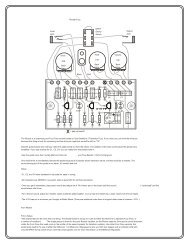
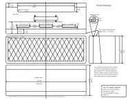
Terminal strip method. This is most like the original construction of the Dallas<br />
point terminal strip versus PCB construction for this device) then you can make<br />
Rangemaster. Procure six-lug terminal strip, such as a Mouser part number<br />
<strong>one</strong> either of two different ways.<br />
158-1006. <strong>The</strong> lugs on either end of this strip serve as mounting and ground<br />
points, since they each have a foot that can be screwed in<strong>to</strong> the chassis.<br />
Choose <strong>one</strong> end and number the lugs <strong>one</strong> <strong>to</strong> six from that end, the starting lug<br />
being “1”. Lug 1 will be the ground point for the circuit. In this order, insert<br />
comp<strong>one</strong>nts, dress and clip their leads, and finally once all comp<strong>one</strong>nts are in,<br />
solder:<br />
Note: if only <strong>one</strong> lug is specified, only <strong>one</strong> end of the comp<strong>one</strong>nt is connected.<br />
1. 47uF(+ <strong>to</strong> L1): L1- L4<br />
2. 47uF(+ <strong>to</strong> L1): L1 – L5<br />
3. 470K: L3 – L5<br />
4. Two ground wires: L1<br />
5. Collec<strong>to</strong>r wire: L2<br />
6. Input capaci<strong>to</strong>r: L3<br />
7. Power wire: L5<br />
8. Solder the wires at the lugs.<br />
9. Add the transis<strong>to</strong>r, collec<strong>to</strong>r <strong>to</strong> L2, base <strong>to</strong> L3, emitter <strong>to</strong> L4. Use a heat<br />
sink between the solder joint and body of the transis<strong>to</strong>r when you solder the<br />
device or you may ruin it! Note that you must heatsink the transis<strong>to</strong>r lead<br />
each time you solder or unsolder a joint that connects <strong>to</strong> the transis<strong>to</strong>r in<br />
the following two steps. This is important!!<br />
10. Temporarily tack-solder the 100K tuning pot with wires from L1 <strong>to</strong> L3 and<br />
the 10K from L1 <strong>to</strong> L4, then perform the tuning process.<br />
11. With the resis<strong>to</strong>r values determined in the tuning process, insert the Re<br />
resis<strong>to</strong>r from L1 <strong>to</strong> L4 and the Rb1 resis<strong>to</strong>r from L1 <strong>to</strong> L3 and solder them<br />
in.<br />
12. Position the terminal strip assembly in the box you’re going <strong>to</strong> use and<br />
connect up the wires:<br />
• solder the ground wires <strong>to</strong> input and output jacks ground lugs<br />
• power wire <strong>to</strong> the “cold” lug of the boost set pot (the <strong>one</strong> that the wiper<br />
connects <strong>to</strong> when fully counterlcockwise)<br />
• collec<strong>to</strong>r wire <strong>to</strong> the “hot” lug of the boost set pot<br />
• base capaci<strong>to</strong>r <strong>to</strong> the bypass switch<br />
13. Solder the output capaci<strong>to</strong>r from the wiper of the boost set pot <strong>to</strong> the<br />
bypass switch<br />
14. Battery connec<strong>to</strong>r (-, black) wire <strong>to</strong> the bypass switch<br />
15. Battery connec<strong>to</strong>r (+, red) wire <strong>to</strong> the input jack stereo signal lug
Austin Treble Blaster Austin Treble Blaster<br />
Trace-your-own PCB method. Clean a suitable sized board blank of all traces of<br />
oil, dirt, and oxidation with a scouring cleanser and dry. Tape a bit of carbon<br />
paper over the board blank and over that tape the Trace Your Own board<br />
layout. Trace the layout on<strong>to</strong> the copper with a ball point pen. <strong>The</strong>n, remove the<br />
layout and tracing paper, and using a suitable etch-resist pen (Radio Shack sells<br />
them) ink in the pattern directly on the copper, trying <strong>to</strong> make it match the<br />
original layout. You can <strong>to</strong>uch up any goofs by scraping the marker off with a<br />
sharp pointed knife for small mistakes or by wiping the board blank clean with<br />
a solvent and starting over for big errors. Once you’re satisfied with the layout<br />
pattern, etch with your favorite etchant. Note that the Trace-Your-Own pattern<br />
is intended for <strong>to</strong>p side soldering; you will solder parts on the copper side of the<br />
board. Note that using this method you will have <strong>to</strong> use the miniature 16mm<br />
control for the boost set pot <strong>to</strong> have enough room inside the recommended cast<br />
aluminum box, as the parts sit slightly higher than in ordinary pin-in-hole<br />
boards.<br />
T<br />
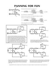
£ erminal Strip Method<br />
L1 L2 L3 L4 L5 L6<br />
(1., 2.)<br />
Insert wires in<strong>to</strong> terminal lug<br />
and wrap until the wire will<br />
stay in the lug without solder.<br />
Standard drilled PCB method. Using the T<strong>one</strong>r Transfer Pattern, copy the<br />
layout <strong>to</strong> your favorite <strong>to</strong>ner transfer medium (I prefer Techniks Press-N-Peel<br />
Blue) and iron it on<strong>to</strong> a board blank cleaned as above. Drill the holes in the<br />
pads and stuff the board as indicated.<br />
Cin<br />
(3, 4,5,<br />
6, 7)<br />
Insert multiple wires before<br />
soldering lug.<br />
<strong>The</strong> wiring diagrams and assembly diagrams for the PCB approaches apply <strong>to</strong><br />
both PCB methods.<br />
470K<br />
(9)<br />
[Note: 11/24/98 PCB layouts will be added shortly]<br />
Filling the lug with solder<br />
¡ is not necessary.<br />
(11)<br />
Heat sink transis<strong>to</strong>r leads with<br />
¢ needle nosed pliers or hemostats<br />
when soldering!!!!!!<br />
Re<br />
Rb1<br />
¤
Austin Treble Blaster Austin Treble Blaster<br />
Parts List and Suppliers<br />
Part Description Mouser PN M $ Qty<br />
1<br />
2<br />
0.25<br />
OC44 [1] PNP Germanium N/A- alternates<br />
transis<strong>to</strong>r<br />
available from GEO<br />
47uF Al Electro Cap 140-XAL16V47 (axial)<br />
-OR-<br />
140-XRL16V47 (radial)<br />
0.07<br />
0.005 <strong>to</strong> 0.01uF Capaci<strong>to</strong>r, film see text 1<br />
0.01uF (10nF) Capaci<strong>to</strong>r, film, 140-PF2A103K 0.14 1<br />
4.7K nominal 1/4W resis<strong>to</strong>r – see text 0.07 1<br />
68K nominal 1/4W resis<strong>to</strong>r – see text 0.07 1<br />
470K 1/4W resis<strong>to</strong>r 29SJ250-470K 0.07 1<br />
2.2M optional 1/4W resis<strong>to</strong>r 29SJ250-2.2M 0.07 2<br />
10K “B” Audio Taper Pot 313-4000-10K 1.74 1<br />
1590B [3] Box, Cast Alum. [3] 546-1590B 8.53 1<br />
DPDT [4] DPDT s<strong>to</strong>mp switch [4] N/A, alternates 10.00 1<br />
available from GEO <strong>to</strong><br />
16.00<br />
¼” jack 1-ckt Mono ph<strong>one</strong> jack 16PJ023 1.22 1<br />
¼” jack 2-ckt Stereo ph<strong>one</strong> jack 16PJ081 1.31 1<br />
Terminal strip [5] Terminal strip, six lugs 158-1006 0.57 1<br />
9v battery clip 12BC092 0.38 1<br />
#22 - #24 AWG stranded hookup wire<br />
knobs 1<br />
Notes:<br />
[1] OC44 was the original part number. This part is available only by the sheerest<br />
chance anymore. You can use most PNP germanium types if you can find on with a gain<br />
between 65 and 100, adjusting as noted in the text. Actual pro<strong>to</strong>types with type number<br />
NKT275, 2N527, 2N508, 2N404, and 2SB75 have worked very well. <strong>The</strong> replacement<br />
part ECG158 works well sometimes if you can get the right <strong>one</strong>. See if you can get the<br />
guy at the service counter <strong>to</strong> let you poke the leads through the plastic bag and test the<br />
gain at the counter before buying.<br />
[2]<strong>The</strong>se values are determined by experiment in the tuning of the pedal. You will need<br />
a 100K and a 10K pot temporarily for the tuning process.<br />
[3]<strong>The</strong> Hammond 1590B is a comfortable fit for this effect. You can also use the Eagle<br />
equivalent, the Mouser part number 400-4591, which is a bit cheaper at $7.35.<br />
[4]Mouser does not have suitable s<strong>to</strong>mp switches. <strong>The</strong> Carling 317P is the old standard,<br />
and is available through Stewart Macdonald Luthier supply for about $17. Another<br />
usable <strong>one</strong> is the “Arrow” DPDT available through GEO for $8.50 at the time of this<br />
writing.<br />
[5] <strong>The</strong> terminal strip should only be bought if you are doing the hand-wired version. It<br />
is not needed for the PCB versions.