Hydrogen peroxide etching and stability of P-type poly-SiGe films ...
Hydrogen peroxide etching and stability of P-type poly-SiGe films ...
Hydrogen peroxide etching and stability of P-type poly-SiGe films ...

Create successful ePaper yourself
Turn your PDF publications into a flip-book with our unique Google optimized e-Paper software.
HYDROGEN PEROXIDE ETCHING AND STABILITY OF P-TYPE POLY-SIGE FILMS<br />
'B.L. Bircumshaw, 'ML. Wasilik, 'E.B. Kim, 'ER. Su, 2H. Takeuchi, 'C.W. Low, 'G. Liu,<br />
'.'A.P. Pismo, 2T.-.I King, <strong>and</strong> ','R.T. Howe<br />
I<br />
Departments <strong>of</strong> Mechanical Engineering <strong>and</strong> 'Electrical Engineering <strong>and</strong> Computer Sciences<br />
Berkeley Sensor & Actuator Center, University <strong>of</strong> California, Berkeley, CA 94720-1774, USA<br />
ABSTRACT<br />
In this paper, a model is developed for the <strong>etching</strong> <strong>of</strong> as-<br />
deposited, in-situ, boron-doped, LPCVD <strong>poly</strong>-<strong>SiGe</strong> <strong>films</strong><br />
in hydrogen <strong>peroxide</strong>. The model is corroborated by<br />
<strong>etching</strong> results for <strong>poly</strong>-<strong>SiGe</strong> alloys with Ge content<br />
between SS <strong>and</strong> 70%. The results indicate that Ge<br />
content in the 55 to 65% range is desirable for<br />
maintaining high selectivity with respect to <strong>poly</strong>-Ge<br />
sacrificial layers in a <strong>peroxide</strong> etch while attaining a<br />
<strong>poly</strong>crystalline film structure (at ahont 42S'C, 50% Ge<br />
content <strong>poly</strong>-<strong>SiGe</strong> <strong>films</strong> are amorphous). The drift in<br />
residual stress <strong>of</strong> <strong>poly</strong>-<strong>SiGe</strong> <strong>films</strong> at room temperature in<br />
dry <strong>and</strong> wet ambients is also reported. Finally, the<br />
<strong>etching</strong> <strong>of</strong> in-sifu, boron-doped, LPCVD <strong>poly</strong>-Ge <strong>films</strong> in<br />
hydrogen <strong>peroxide</strong> is studied.<br />
1. INTRODUCTION<br />
Polycrystalline silicon-germanium (<strong>poly</strong>-<strong>SiGe</strong>) is a<br />
promising material for the integration <strong>of</strong> surface<br />
micromachined MEMS (microelectromechanical systems)<br />
with electronics. The process flow for <strong>poly</strong>-<strong>SiGe</strong> MEMS<br />
fabrication is similar to that for conventional <strong>poly</strong>-Si MEMS<br />
fabrication. In this case, however, <strong>poly</strong>-<strong>SiGe</strong> replaces <strong>poly</strong>-<br />
Si as the structural material, while <strong>poly</strong>-Ge can serve as the<br />
sacrificial material instead <strong>of</strong> silicon dioxide. This enables<br />
the use <strong>of</strong> hydrogen <strong>peroxide</strong> (H202) as the release etchant<br />
instead <strong>of</strong> hydr<strong>of</strong>luoric acid (HF). Peroxide selectively<br />
etches <strong>poly</strong>-Ge over <strong>poly</strong>-<strong>SiGe</strong>. The selectivity, though, is<br />
dependent on doping conditions <strong>and</strong> the Ge content <strong>of</strong> the<br />
SiCe alloy.<br />
Conventional LPCVD (low pressure chemical vapor<br />
deposition) techniques can be used to deposit conformal<br />
<strong>poly</strong>-<strong>SiGe</strong> <strong>and</strong> <strong>poly</strong>-Ge <strong>films</strong> at temperatures below 425'C<br />
[1,2]. Consequently, <strong>poly</strong>-<strong>SiGe</strong> MEMS can be micro-<br />
machined on top <strong>of</strong> modem foundry CMOS circuitry.<br />
Furthermore, research by Sedky et al. has shown that Al-<br />
metallized CMOS can be annealed at temperatures up to<br />
525T for 90 minutes without significant harm to the<br />
underlying electronics [3].<br />
Micromachined resonators can exhibit very high<br />
mechanical quality factors. Indeed, unannealed <strong>poly</strong>-<strong>SiGe</strong><br />
MEMS resonators deposited at 425'C have been reported to<br />
have Qs in excess <strong>of</strong> 30,000 [4]. Due to their high Q's,<br />
MEMS resonators arc promising as replacements for discrete<br />
filters <strong>and</strong> oscillators in wireless communications systems<br />
[5,6]. Integrating RF MEMS directly with CMOS promises<br />
to drop parasitic capacitances <strong>and</strong> inductances, as well as<br />
0-7803-8265-X/04/$l7.00 02004 IEEE. 514<br />
reduce fabricationiintegration costs <strong>and</strong> the form factor <strong>of</strong><br />
telecommunications devices.<br />
After reviewing the problem with etch selectivity that<br />
motivated this research, we discuss how Ge content was<br />
determined in our processes. A model for the <strong>peroxide</strong><br />
<strong>etching</strong> <strong>of</strong> in-situ, boron-doped (p-<strong>type</strong>), LPCVD <strong>poly</strong>-<strong>SiGe</strong><br />
is then presented, <strong>and</strong> the etch rate <strong>of</strong> in-situ, boron-doped,<br />
LPCVD <strong>poly</strong>-Ge is tabulated. Finally, the <strong>stability</strong> <strong>of</strong> in-sifu,<br />
boron-doped <strong>poly</strong>-<strong>SiGe</strong> <strong>films</strong> at room temperature is studied<br />
by measuring their average stress in dry <strong>and</strong> wet ambients.<br />
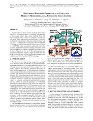
2. SIDEWALL SPACER RF RESONATOR PROCESS<br />
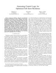
A five-mask, sidewall-spacer process was employed in an<br />
attempt to fabricate <strong>poly</strong>-<strong>SiGe</strong> RF electrostatic resonators<br />
with ultra-narrow gaps (Fig. 1). To remain compatible with<br />
post-CMOS fabrication, all process temperatures were kept<br />
at or helow 425T, with the exception <strong>of</strong> two LTO (low<br />
temperature oxide) depositions at 450'C. Gaps between 80<br />
<strong>and</strong> 100 nm were achieved on 2.4 pm <strong>poly</strong>-SiCe <strong>films</strong><br />
(Fig. 2a). After a one-hour release in 90T hydrogen<br />
<strong>peroxide</strong>, however, the gaps widened precipitously (Fig. 2h).<br />
EEzEz3<br />
*540.Y.J.T0 SD~rn_, ..d,Idll<br />
P*~GIIIP<br />
, *,. , ., ., (.ld"".M ly.ee<br />
, ".(I.. .,<br />
26 &""L-T-Fm.*".i**g.To~<br />
\I" (. cr sa- s"b-.c.<br />
Id $" Lar 7e"ps.(lu. Odd. @To)<br />
3Ln#*C?.N LilicOS.b,ed- 1<br />
Figure I: Cross-seclions <strong>of</strong> the low-temperarure,<br />
sidewall-spacer process employed to fabricate highfrequency<br />
resonators. Poly-<strong>SiGe</strong> is used as the structural<br />
material, while<strong>poly</strong>-Ge is used as the sacrrficial material.
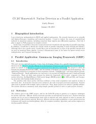
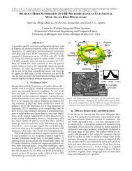
By visual examination <strong>of</strong> Fig. 2, <strong>and</strong> assuming a linear<br />
etch rate, we found that in-situ, boron-doped <strong>poly</strong>-Sio.31Geo.c9<br />
etches at a rate <strong>of</strong> approximately 0.24 pulu (40 kmin).<br />
This etch rate is at least 40 times higher than that reported for<br />
undoped <strong>poly</strong>-Sio.,GeO7 <strong>films</strong> [2,7]. As will he discussed in<br />
Section 4, the etch rate <strong>of</strong> <strong>poly</strong>-<strong>SiGe</strong> is, in fact, non-linear<br />
From the SEMs, in-situ, boron-doped <strong>poly</strong>-Ge was found to<br />
etch at a rate <strong>of</strong> at least 0.5 Wmin; at least 60% faster than<br />
undoped <strong>poly</strong>-Ge [SI.<br />
It is clear from these experimental results that boron<br />
doping greatly enhances the etch rate <strong>of</strong> both <strong>poly</strong>-Ge <strong>and</strong><br />
<strong>poly</strong>-<strong>SiGe</strong> <strong>films</strong> in <strong>peroxide</strong>. This enhancement is greater for<br />
<strong>SiGe</strong> compared to Ge, reducing the selectivity <strong>of</strong> <strong>peroxide</strong> as<br />
a release for boron-doped <strong>SiGe</strong> structures with Ge as the<br />
sacrificial. Moreover, the Ge content <strong>of</strong> the deposited <strong>films</strong><br />
was several atomic percent higher than expected. These<br />
findings indicated the need for us to more fully characterize<br />
our <strong>poly</strong>-<strong>SiGe</strong> <strong>and</strong> <strong>poly</strong>-Ge <strong>films</strong>.<br />
3. CHARACTERIZING GE CONTENT OF THE<br />
LPCVD POLY-SIGE<br />
Precise control <strong>of</strong> Ge content is critical for <strong>poly</strong>-Sil.,Ge,<br />
MEMS technology. Peroxide etch rate, internal stress,<br />
resistivity, strain gradient, <strong>and</strong> deposition rate are all<br />
dependent to some degree on Ge content.<br />
Unless othenvise stated, all <strong>poly</strong>-<strong>SiGe</strong> <strong>films</strong> described in<br />
this paper were deposited at 425T <strong>and</strong> 400mTorr in a<br />
conventional, horizontal LPCVD furnace. The total gas flow<br />
rate was fixed at 220 sccm, <strong>and</strong> the flow rates <strong>of</strong> SiH4 <strong>and</strong><br />
GeH4 were varied. For in-silu, boron-doped processes, the<br />
B2H6 (10% in H2) flow rate was set at 60 sccm, while for<br />
undoped processes, the N2 flow rate was set at 60 sccm.<br />
Figure 2: Cross-sectional SEMs <strong>of</strong> completed slruclures<br />
fabricated with the sidewall-spacer process @er release in<br />
90%<strong>peroxide</strong> for: I30 seconds (a) <strong>and</strong>one hour (b).<br />
515<br />
To study the dependence <strong>of</strong> Ge content on process<br />
conditions, multiple <strong>poly</strong>-<strong>SiGe</strong> <strong>films</strong> <strong>of</strong> varying Ge content<br />
were deposited, one on top <strong>of</strong> another. After depositions,<br />
SlMS (secondaly ion mass spectrometly) was used to<br />
quantify the atomic composition <strong>of</strong> these multilayer stacks.<br />
For each set <strong>of</strong> process conditions, wafer position<br />
dependence was also examined.<br />
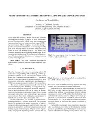
It was found that the Ge content <strong>of</strong> the <strong>films</strong> varied nearly<br />
linearly with the ratio <strong>of</strong> GeH4 to (GeH4 + SiH,) flow rates<br />
over the 62 to 75% Ge content region (Fig. 3). The<br />
difference in Ge content between wafer positions is attributed<br />
to the loading effect inside the furnace.<br />
It is important to note that the Ge contents <strong>of</strong> the <strong>films</strong><br />
used in this paper were determined by curve-fitting the<br />
results in Fig. 3, not direct SlMS analysis <strong>of</strong> each film. The<br />
direct accuracy <strong>of</strong> SIMS analysis for Ge content is about<br />
i 2% (Ge content). The SIMS data indicated that Ge <strong>and</strong>/or<br />
Si interdiffusion took place at the interface hetween different<br />
Ge content <strong>poly</strong>-<strong>SiGe</strong> alloys at 425OC. This phenomenon has<br />
been reported upon in the literature [9]. Despite the<br />
interdiffusion, the multilayer stacks exhibited a stepped<br />
pr<strong>of</strong>ile.<br />
To ensure that the multilayer Ge contents were correct,<br />
SlMS analysis was used to measure the Ge content in single<br />
layer <strong>poly</strong>-<strong>SiGe</strong> <strong>films</strong> deposited under the same conditions as<br />
specific layers <strong>of</strong> the multilayer stacks. The single film <strong>and</strong><br />
multilayer Ge contents were compared <strong>and</strong> found to he in<br />
agreement to within i 1.8% (typically, the agreement was<br />
better than i 0.8%). The discrepancy between the two<br />
measurements is attributed to fluctuations in LPCVD<br />
conditions (flow rates, doping concentrations, temperature,<br />
etc.) <strong>and</strong> Ge interdiffusion in the multilayer <strong>films</strong>.<br />
4. PEROXIDE ETCHING OF POLY-SIGE<br />
Qualitative Observations <strong>of</strong> Peroxide Etching<br />
Peroxide <strong>etching</strong> <strong>of</strong> high Si content (i.e., < 60% Ge content)<br />
<strong>poly</strong>-<strong>SiGe</strong> alloys results in little alteration <strong>of</strong> the original film<br />
for etches under one hour long. Peroxide <strong>etching</strong> <strong>of</strong> high Ge<br />
content <strong>poly</strong>-<strong>SiGe</strong> alloys results in <strong>films</strong> that steadily darken<br />
<strong>and</strong> become more “glassy” (exhibiting reflective properties<br />
<strong>and</strong> coloration common to thin oxides) the longer the <strong>films</strong><br />
are etched (Fig. 4). An HF dip makes the <strong>films</strong> duller,<br />
indicating that the glassy substance has been removed.<br />
Cross-sectional SEMs <strong>of</strong> a <strong>poly</strong>-<strong>SiGe</strong> alloy with<br />
E 74%<br />
E 72% GPE Inlet Position<br />
70%<br />
’ 62%<br />
6 66%<br />
0 64%<br />
60%<br />
0.35 0.40<br />
Flow Ratio[ GeH,I(GeH,+SiH,)l<br />
Figure3: Ge content vs. CeH4 to (GeH4 + SiHJ flow<br />
ratio for in-situ, boron-dopedprocesses.
approximately 66% Ge content that has been etched under a<br />
variety <strong>of</strong> conditions is presented in Fig. Sa-d. A post-<br />
<strong>peroxide</strong> etch HF dip removes the silicon dioxide created<br />
during the H202 etch (compare Figs. 5c <strong>and</strong> 5d). An HF dip<br />
before the H202 etch will enhance <strong>peroxide</strong> <strong>etching</strong> (compare<br />
Figs. 5h <strong>and</strong> 5d).<br />
Fig. 5d appears to indicate that the H202 is attacking<br />
along grain boundaries (spaced several 100 nm apart at this<br />
deposition temperature). The exact mechanism for enhanced<br />
<strong>etching</strong> along grain boundaries <strong>and</strong> along interfacial surfaces<br />
is unknown. From SIMS analysis, however, it is known that<br />
- 66% Ge min<br />
mi" min min<br />
0 30 60<br />
-65%"<br />
- 62% Ge<br />
min<br />
0<br />
mm<br />
30<br />
min<br />
60<br />
-63%'' mill<br />
min<br />
min min<br />
Figure 4: Qualitative assessment <strong>of</strong> the characteristics oj<br />
90°C <strong>peroxide</strong> <strong>etching</strong> <strong>of</strong><strong>films</strong> <strong>of</strong> varying Ge content. The<br />
left-h<strong>and</strong>figure shows the effect <strong>of</strong>vaiying Ge content for<br />
different etch times. The right-h<strong>and</strong> figure provides a<br />
derailed view <strong>of</strong> haw a single film darkens as the etch<br />
proceeds. The schematics below the figures indicate the<br />
approximate Ge content <strong>of</strong>the<strong>films</strong> <strong>and</strong> the amount <strong>of</strong>time<br />
they were etched in H20,. No pre- or post-etch HF dip was<br />
performed on these samples. The <strong>poly</strong>-<strong>SiGe</strong> alloys were<br />
depositedat 450°C <strong>and</strong> 600 mTorr.<br />
10secHF(10:1),3OminH,O, 10secHF(10:1),30minH20,,<br />
lOsecHF(10:l)<br />
Figure 5: Cross-sectional SEMs <strong>of</strong>a <strong>poly</strong>-<strong>SiGe</strong> alloy with<br />
- 66% Ge content before <strong>and</strong> after c1 30 minute immersion<br />
in 90°C H20, with <strong>and</strong> without a preceding HF dip. The<br />
<strong>poly</strong>-<strong>SiGe</strong>film was deposited at 450°C <strong>and</strong> 600 mTorr.<br />
516<br />
the <strong>films</strong> are degenerately boron-doped (- 3~10'~ to 5~10~'<br />
boron atomsicm', with this variation exhibited across the<br />
load). Thus, the grain boundary enhanced <strong>etching</strong> is likely<br />
' due to boron segregation.<br />
It should he noted that a separate injector is used for<br />
introducing B2H6 into our LPCVD furnace. The high degree<br />
<strong>of</strong> cross-load variation in the boron-doping appears to he due<br />
to non-uniformities in the B2H6 flow pr<strong>of</strong>ile resulting from<br />
the condition <strong>of</strong> the current injector.<br />
Proposed Poly-SiCe Etch Mechanism<br />
Previous work had assumed that the etch rate <strong>of</strong> <strong>poly</strong>-<strong>SiGe</strong> in<br />
<strong>peroxide</strong> is linear with respect to time [7,8]. Heck observed<br />
SiOz <strong>and</strong> GeOz growth on the surface <strong>of</strong> <strong>poly</strong>-<strong>SiGe</strong> during<br />
<strong>peroxide</strong> <strong>etching</strong> [SI. He proposed that once the<br />
concentration <strong>of</strong> Si atoms in the surface oxide reached a<br />
critical value (- 50%), the etch would be arrested. For Si<br />
contents below this critical value, he predicted a linear etch<br />
rate with time.<br />
In this paper, we propose an etch mechanism analogous<br />
to the model developed by Deal <strong>and</strong> Grove in 1965 to<br />
explain the thermal oxidation <strong>of</strong> silicon [lo,] I]. Chemically,<br />
the model can be described as follows:<br />
2H202 + <strong>SiGe</strong> + GeO + Si0 + 2Hz0<br />
H2O2 + Si0 -* Si02 + HzO<br />
H2OZ + GeO a GeO, f HZO<br />
HzO + Ge02(s) + H20 + Ge02(aq)<br />
As a strong oxidizer, hydrogen <strong>peroxide</strong> is presumed to<br />
oxidize Si <strong>and</strong> Ge atoms exposed on the surface <strong>of</strong> the <strong>poly</strong>-<br />
<strong>SiGe</strong> film. The Si is converted into Si02 <strong>and</strong> the Ge into<br />
Ge02. While SiOz is stable in H20, Ge02 is water-soluble.<br />
Because <strong>peroxide</strong> is typically available as a saturated<br />
solution <strong>of</strong> 30% H202 <strong>and</strong> 70% H20, the germanium dioxide<br />
is dissolved, leaving behind a porous silicon dioxide film.<br />
Overall, for <strong>films</strong> with high Ge content, material volume is<br />
removed as the Ge02 is dissolved, resulting in the <strong>etching</strong> <strong>of</strong><br />
<strong>poly</strong>-<strong>SiGe</strong> micromachined structures.<br />
At first, the <strong>etching</strong> is reaction-rate limited. However, as<br />
the etch continues, the porous Si02 layer thickens, restricting<br />
the flux <strong>of</strong> reactants to, <strong>and</strong> the flux <strong>of</strong> products from, the<br />
<strong>SiGe</strong>Si02 interface. Hence, the etch rate is diffusion-<br />
limited for long etch times.<br />
Assuming first order kinetics <strong>and</strong> steady state diffusion,<br />
the etch mechanism described by Eqn. 1 can be modeled by a<br />
simple quadratic equation:<br />
where I is time <strong>and</strong> X = X(t) is the thickness <strong>of</strong> removed<br />
material (drop in step height), while A, B, <strong>and</strong> rare constants.<br />
A thin layer <strong>of</strong> Si02 <strong>and</strong> Ge02 is present on <strong>poly</strong>-<strong>SiGe</strong> <strong>films</strong><br />
exposed to oxygen. The time it would take <strong>peroxide</strong> to<br />
create <strong>and</strong> etch this oxide is represented by r.<br />
For short etches, where (t + r)
.<br />
In this regime, the etch rate is proportional to the square root<br />
<strong>of</strong> time, <strong>and</strong> B is the parabolic etch rate constant.<br />
Etch Rate Measurement Method<br />
Single layer, in-situ, boron-doped <strong>poly</strong>-SiCe thin <strong>films</strong> <strong>of</strong><br />
varying Ge content were deposited on single crystal silicon<br />
(SCS) wafers, as well as SCS wafers covered by a 1 to 3 pm<br />
LTO film. The <strong>SiGe</strong> <strong>films</strong> were then patterned<br />
lithographically using reactive ion <strong>etching</strong> (RIE) to create<br />
test structures with twenty 15 pm wide steps, each spaced<br />
15 pm apart. The initial step height was recorded using a<br />
stylus-hued pr<strong>of</strong>ilometer with sub-Angstrom resolution <strong>and</strong><br />
8 A or 0.1% step height repeatability. Due to the high index<br />
<strong>of</strong> refraction <strong>of</strong> high Ge content <strong>films</strong> <strong>and</strong> the high IR (infra-<br />
red) absorption <strong>of</strong> boron, the optical techniques available to<br />
us could not he employed for step height measurements.<br />
Each step height was an average <strong>of</strong> the twenty step<br />
heights <strong>of</strong> the test structure. St<strong>and</strong>ard deviations over the<br />
twenty measurements ranged from I to 10 nm, <strong>and</strong> were<br />
typically on the order <strong>of</strong> 2 to 3 nm. Each wafer was<br />
measured in two to ten different locations.<br />
After the initial step height measurements, the patterned<br />
wafers were dipped in a bath <strong>of</strong> heated <strong>peroxide</strong>. The<br />
temperature <strong>of</strong> the bath was fixed at 90°C using a hotplate,<br />
temperature sensor @laced roughly two inches above the hot<br />
plate), <strong>and</strong> a feedback controller. Additionally, a<br />
thermometer was used to verify the temperature <strong>of</strong> the bath.<br />
Due to the wafer carrier, in nearly all cases, the <strong>poly</strong>-<strong>SiGe</strong><br />
etch structures were exposed to H20, at a temperature<br />
slightly above 90'C (between 90 <strong>and</strong> 96'C, accounting for<br />
fluctuations in temperature).<br />
After a specific timed etch, the wafers were removed <strong>and</strong><br />
washed thoroughly with deionized water. The average step<br />
heights <strong>of</strong> the test structures were recorded, <strong>and</strong> then the<br />
same wafers were placed.hack in the H202 bath for a<br />
specified time. This process was repeated over a total etch<br />
period <strong>of</strong> between 30 minutes <strong>and</strong> one hour.<br />
It is known that <strong>peroxide</strong> decomposes over time [IZ]. It<br />
is therefore critical that we rnle out the possibility <strong>of</strong> our<br />
measurements being affected by this decomposition. The<br />
oxidation <strong>of</strong> Ge <strong>and</strong> dissolution <strong>of</strong> Ge02 does not vary with<br />
<strong>peroxide</strong> concentrations above 5% [13]. Moreover, it is<br />
-<br />
E<br />
I 300 , , I<br />
5 250<br />
.c<br />
._ al<br />
f 200<br />
P<br />
150<br />
._ c<br />
100 1slTesl Best-Fit<br />
._<br />
L<br />
a 0<br />
50 2nd Test Best-Fit<br />
0 500 1000<br />
Time (sec)<br />
1500 2000<br />
Figure 6: Etched material vs. time for a <strong>SiGe</strong> alloy oj<br />
70.3% Ge content.<br />
517<br />
known that a 30% <strong>peroxide</strong> bath heated at 90'C for 20 hours<br />
will maintain an H202 concentration above 5% [SI. All <strong>of</strong><br />
our measurements were taken within 20 hours <strong>of</strong> heating a<br />
fresh <strong>peroxide</strong> bath. However, to ensure that the <strong>peroxide</strong><br />
did not significantly decompose, we topped <strong>of</strong>f the bath with<br />
fresh H202 periodically. Significant etch rate fluctuations<br />
were not observed after refreshing the bath, indicating that<br />
the bath remained effective over the period <strong>of</strong> the tests.<br />
Poly-SEe Etch Results<br />
Fig. 6 is an example <strong>of</strong> one set <strong>of</strong> experimental results, along<br />
with best-fit quadratic models (Eqn. 2). In this case, a wafer<br />
was broken in half <strong>and</strong> tested on two different days. As can<br />
he seen, OUT model fits the ohserved etch phenomena very<br />
well. However, the model does deviate noticeably in the<br />
short term. This is due to the fact that variations in testing<br />
conditions (temperature, precise etch time, placement <strong>of</strong> the<br />
pr<strong>of</strong>ilometer stylus, etc.) are integrated over the etch time.<br />
For short etches, minor fluctuations have a strong effect on<br />
the measurements. For long etches, variations are averaged<br />
together <strong>and</strong> tend to cancel out.<br />
The parabolic <strong>and</strong> linear etch rate constants were<br />
extracted using a least squares quadratic hest fit. In all cases,<br />
the time constant r was set to zero, which is reasonable since<br />
the initial oxide on the steps was on the order <strong>of</strong> 5 to 30 A<br />
thick. The averaged constants are presented in Figs. 7 <strong>and</strong> 8.<br />
1000<br />
m I<br />
3<br />
-<br />
100<br />
$ 10<br />
0 -:<br />
2: 1<br />
.cz<br />
Y C<br />
0.1<br />
._ -<br />
2 0.07<br />
e<br />
h<br />
0,001<br />
i --<br />
o Undoped<br />
55% 60% 65% 70% 759<br />
Ge Content<br />
Figure 7:<br />
The undnped data was extracted from 121<br />
U 0.2<br />
& 0.1<br />
Parabolic etch rate constant, B vs. Ge content.<br />
3<br />
-0.1<br />
55% 60% 65%<br />
Ge Content<br />
70% 75:<br />
Figure 8: Linear etch rate constunt, BIA vs. Ge content.
For <strong>poly</strong>-<strong>SiGe</strong> <strong>films</strong>, the correlation factor (R2) is typically<br />
greater than 80% above 64% Ge content, the correlation<br />
factor is 99% or better. The correlation factor does drop <strong>of</strong>f<br />
as the Ge content falls. This is due to the fact that very little<br />
material is etched (- I nm), resulting in significant errors in<br />
measurement stemming from inconsistent placement <strong>of</strong> the<br />
pr<strong>of</strong>ilometer stylus. Overall, the most reliable data is the<br />
parabolic etch rate constants for the high Ge content <strong>films</strong>.<br />
It is important to realize that the data in Figs. 6-8 simply<br />
records the drop in step height. It does not necessarily relate<br />
to the lateral etch rate. Moreover, the conductive part <strong>of</strong> the<br />
<strong>films</strong> is actually etched more severely than at first glance:<br />
the step heights recorded here are for <strong>poly</strong>-<strong>SiGe</strong> covered wiih<br />
porous SO2.<br />
5. ETCH RATE OF POLY-GE<br />
The etch mechanism for Poly-Ge is analogous to that <strong>of</strong><br />
<strong>poly</strong>-<strong>SiGe</strong> [SI:<br />
HIOl + Ge + GeO + H1O<br />
HZ02 + GeO + GeOz + HZO<br />
(5)<br />
HIO + Ge02(s) - H,O + Ge02(aq)<br />
In the case <strong>of</strong> <strong>poly</strong>-Ge, however, porous silicon dioxide is not<br />
formed. Hence, the etch rate is, to first order, reaction rate<br />
limited <strong>and</strong>, therefore, linear with time.<br />
The lateral etch rate <strong>of</strong> in-situ, boron-doped (p-<strong>type</strong>),<br />
LPCVD <strong>poly</strong>-Ge was found by depositing a layer <strong>of</strong> <strong>poly</strong>-Ge<br />
on SCS <strong>and</strong> LTO wafers. The <strong>poly</strong>-Ge film was then<br />
covered with a 1 pm LTO film. Next, the LTO film was<br />
patterned into a series <strong>of</strong> ever-widening oxide bridges, each<br />
bridge 1 pm wider than the last. Dice were then etched for<br />
various periods <strong>of</strong> time, <strong>and</strong> the etch length determined by<br />
the widest oxide bridge undercut. The results were then<br />
plotted <strong>and</strong> fit via a least squares method to determine the<br />
etch rate. The results are tabulated in Table 1<br />
One <strong>of</strong> the wafers tested was accidentally dipped for three<br />
seconds in piranha (a 120T solution <strong>of</strong> roughly 56:l<br />
H2S04:H101). The <strong>poly</strong>-Ge appeared to he slightly etched.<br />
Despite this, we continued processing the wafer without<br />
incident. When the etch rate <strong>of</strong> the piranha-dipped <strong>poly</strong>-Ge<br />
was measured, however, we found it to he enhanced by about<br />
80% over those wafers not dipped in piranha.<br />
6. STABILITY OF POLY-SIGE<br />
The <strong>stability</strong> <strong>of</strong> <strong>poly</strong>-<strong>SiGe</strong> <strong>films</strong> when stored at room<br />
temperature was also studied. Roughly 1 pm <strong>of</strong> boron-doped<br />
<strong>poly</strong>-<strong>SiGe</strong> was deposited on oxidized Si wafers at 450°C <strong>and</strong><br />
600 mTorr (approximately 65 to 66% Ge content). As a<br />
control, roughly 1 pm <strong>of</strong> in-situ, phosphorous-doped (n<strong>type</strong>),<br />
LPCVD <strong>poly</strong>-Si was deposited on oxidized Si wafers<br />
at 605°C.<br />
Some <strong>of</strong> the wafers were then annealed for one hour in a<br />
nitrogen ambient at 825°C (1050T for the <strong>poly</strong>-Si control<br />
wafers); the other wafers remained unannealed. The<br />
backside film <strong>of</strong> all wafers was then stripped. The wafers<br />
were then placed in a desiccator or exposed to laboratory<br />
ambient conditions for different lengths <strong>of</strong> time. During the<br />
study, some wafers were oxidized or coated with a SAM<br />
(self-assemhled monolayer). Using wafer curnature, average<br />
518<br />
Table I: Etch rate <strong>of</strong> doped <strong>and</strong> undoped <strong>poly</strong>-Ge, <strong>and</strong><br />
the corelaiion coeficient <strong>of</strong> the least squares bestrfit line.<br />
ne undoped data is from 181.<br />
Undoped Poly-Ge I 0.31 pdmin I NIA<br />
Doped Poly-Ge I OS2 pdmin I 91.6%<br />
Doped Poly-Ge After<br />
3 Sec Dip in Piranha<br />
0,94 pdmin 84.0%<br />
film stress was measured regularly over a 7%-month period<br />
(Fig. 9).<br />
Unannealed <strong>SiGe</strong> wafers in ambient conditions exhibited<br />
an increasingly tensile average film stress, while those in the<br />
desiccator maintained a constant stress. We observed no<br />
stress drift in the annealed <strong>poly</strong>-<strong>SiGe</strong> wafers, even in ambient<br />
conditions. The unannealed <strong>and</strong> annealed <strong>poly</strong>-Si control<br />
wafers exhibited no stress drift, regardless <strong>of</strong> ambient<br />
conditions (wet or dry).<br />
Low temperature (360°C) wet oxidation does not appear<br />
to affect the stress drift in <strong>poly</strong>-<strong>SiGe</strong>. Stresses in those<br />
wafers oxidized jumped after the oxidation, but then<br />
continued their original trend, either drifting upward (i.e.,<br />
unannealed wafers in the ambient) or maintaining a constant<br />
stress (i.e., unannealed wafers in the desiccator or annealed<br />
wafers in the ambient or desiccator). Hexamethyldisilazane<br />
(HMDS) <strong>and</strong> the water-based SAM coating Siliclad (from<br />
Gelest Inc., [14]) do not appear to halt the stress drift <strong>of</strong> the<br />
unannealed <strong>SiGe</strong> <strong>films</strong> in ambient conditions.<br />
SlMS analysis <strong>of</strong> the atomic composition <strong>of</strong> an annealed<br />
<strong>and</strong> unannealed, 63% Ge content <strong>SiGe</strong> alloy exposed to<br />
0 50 100 150 200<br />
Time (days)<br />
Figure 9: At Day 0, <strong>SiGe</strong>J, 4, 5, <strong>and</strong> 6 were ununnealed.<br />
while <strong>SiGe</strong>9 was annealed at 825°C in N2 for one hour. All<br />
wafers were left out in ambient conditions on Day 0. The<br />
events labeled in thefigure above are as follows:<br />
I.<br />
2.<br />
3.<br />
4.<br />
5.<br />
6.<br />
7.<br />
8.<br />
Day 4: placed <strong>SiGe</strong>3 in desiccator<br />
Day 47: took <strong>SiGe</strong>3 out <strong>of</strong> desiccator<br />
Day 55: placed <strong>SiGe</strong>6 in desiccator<br />
Day 70: placed <strong>SiGe</strong>4 <strong>and</strong> 5 in desiccator<br />
Dq 147: took SiCe6 out <strong>of</strong> desiccator, oxidized<br />
<strong>SiGe</strong>-3. 6, <strong>and</strong> 9 in steam at 360°C for 1 hr<br />
Day 165: took <strong>SiGe</strong>5 out <strong>of</strong> desiccator<br />
Day 174: coated <strong>SiGe</strong>3 with HMDS<br />
Day 21 7: coated <strong>SiGe</strong>5 <strong>and</strong> 6 with Siliclad
ambient conditions is presented in Fig. IO. Two days after<br />
deposition <strong>of</strong> the film, the wafer was broken in half; one half<br />
<strong>of</strong> the wafer was annealed for five hours in N2 at 450"C,<br />
while the other half remained unannealed. The SlMS<br />
analysis was performed 29 days after the film deposition. In<br />
the interim, between deposition <strong>and</strong> SIMS analysis, the wafer<br />
halves were stored in laboratory ambient conditions.<br />
The B, Ge, <strong>and</strong> Si pr<strong>of</strong>iles (not shown) were not<br />
noticeably affected by the anneal. The atomic concentrations<br />
<strong>of</strong> H <strong>and</strong> 0, on the other h<strong>and</strong>, increased more substantially<br />
at the surface <strong>of</strong> the unannealed film compared to the<br />
annealed film. Integrating the curves, it was found that the<br />
unannealed sample contained 1.9 <strong>and</strong> 1.4 times more H <strong>and</strong><br />
0, respectively, than the annealed sample. Accounting for<br />
residual 0 <strong>and</strong> H from the deposition process, we found that<br />
the unannealed film absorbed about 1.8 times more 0 than H.<br />
The higher 0 incorporation into the unannealed film suggests<br />
that the stress drift <strong>of</strong> <strong>SiGe</strong> <strong>films</strong> is due to a water-mediated<br />
introduction <strong>of</strong> oxygen <strong>and</strong> hydrogen into the <strong>SiGe</strong> film, not<br />
simply water absorption. Exposing the front side <strong>of</strong> the<br />
unannealed <strong>SiGe</strong> wafers in the stress drift experiment to HF<br />
results in virtually no change in the average stress. This<br />
indicates that oxidation is not the mechanism causing the<br />
stress drift (Fig. 9) <strong>and</strong> higher 0 incorporation (Fig. IO).<br />
7. CONCLUSIONS<br />
In order to use <strong>poly</strong>-Ge sacrificial layers, release steps for<br />
<strong>SiGe</strong> <strong>films</strong> with t 65% Ge content must he time-limited due<br />
to the high etch rate <strong>of</strong> <strong>SiGe</strong> in <strong>peroxide</strong>. To maintain their<br />
stress <strong>stability</strong>, unannealed <strong>poly</strong>-<strong>SiGe</strong> MEMS should be<br />
encapsulated in a relatively dry ambient.<br />
For RF MEMS resonators, the restrictions are more<br />
severe. Most RF electrostatic resonators require gaps <strong>of</strong><br />
- 100 nm or smaller [IS]. Unfortunately, a IS-minute<br />
release etch will more than double the gap width <strong>of</strong> a <strong>poly</strong>-<br />
Sio.,lGeo.6g resonator, increasing the motional resistance <strong>of</strong><br />
the device more than 16-fold. However, this problem can he<br />
resolved without significant alteration <strong>of</strong> the process flow by<br />
increasing the Si content <strong>of</strong> the <strong>poly</strong>-<strong>SiGe</strong> <strong>films</strong>, thereby<br />
lE121<br />
._<br />
1 2 1E+20 ~<br />
I 5= 9<br />
' 1E+19<br />
9<br />
-HAnnealed -0Annealed<br />
-H Unanneeled -0 Unannealed<br />
1E+18<br />
0 01 02 03 04 05 06 0<br />
DeDth luml<br />
Figure IO: SlMS analysis <strong>of</strong> the atomic composition <strong>of</strong> an<br />
unannealed <strong>and</strong> annealed @ve hours in N2 at 450°C). 63%<br />
Ge content <strong>SiGe</strong> alloy 29 days afrer deposition (27 days ajier<br />
the anneal) The Si, Ge, <strong>and</strong> B pr<strong>of</strong>iles (not shown) were no/<br />
noticeably affected by the anneal. The <strong>poly</strong>-SiCe fihn wus<br />
deposited at 425°C <strong>and</strong> 600 mTorr.<br />
lowering the etch rate <strong>of</strong> the <strong>films</strong> in <strong>peroxide</strong> <strong>and</strong> increasing<br />
the etch selectivity between <strong>poly</strong>-Ge <strong>and</strong> <strong>poly</strong>-<strong>SiGe</strong>.<br />
One should note, however, that, as the Ge content<br />
approaches 50%, the <strong>SiGe</strong> <strong>films</strong> become amorphous at a<br />
deposition temperature <strong>of</strong> 425°C [Z]. Therefore, the optimal<br />
Ge content which achieves both sufficient etch selectivity<br />
<strong>and</strong> <strong>poly</strong>crystalline film structure is on the order <strong>of</strong> 55 to<br />
65%. Finally, because the gas flow rates have been shown to<br />
strongly affect Ge content in the <strong>poly</strong>-Si,.,Ge, LPCVD<br />
process, precise control <strong>of</strong> gas flow rates is critical.<br />
8. ACKNOWLEDGEMENTS<br />
The authors would like to thank Marie Eyoum for<br />
contributions to Fig. 10, Dimitry Kouzminov for the SlMS<br />
measurements, <strong>and</strong> Marilyn Kushner for making mask sets.<br />
Finally, we wish to thank the DARF'A NMASP program for<br />
their financial support <strong>of</strong> this research.<br />
519<br />
REFERENCES<br />
A.E. Franke, Y. Jiao, M.T. Wu, T.-J. King <strong>and</strong> R.T. Howe, "Post-<br />
CMOS Modular Integration <strong>of</strong> Poly-<strong>SiGe</strong> Micro~tmcNce~ using<br />
Poly-Ge Sacrificial Layers," Technical Di&-csI, Solid-State Sensor<br />
<strong>and</strong> Achlatar Workshop, Hilton Head Is., June 4-8,2000, pp. 18-21<br />
A.E. Franke, "Polycrystalline Silicon-Germanium Films for<br />
Integrated Mierosystems," PhD Disserrarion, Dept. <strong>of</strong> Eleclrical<br />
Engineering <strong>and</strong> Computer Sciences, UC Berkeley, 2000.<br />
S. Sedky. A. WiTvrouw, H. Bender <strong>and</strong> K. Baert, "Experimental<br />
Determination <strong>of</strong> the Maximum Post-Process Annealing<br />
Temperature for St<strong>and</strong>ard CMOS Wafers," IEEE Tra,tsaction.s <strong>of</strong><br />
Elecrron device.^ vol. 48, no. 2,2001, pp. 377-85.<br />
S.A. Bhave, B.L. Bircumshaw, Y.-S. Kim, W.L. Low, T.-J. King<br />
<strong>and</strong> R.T. Howe, "Poly-<strong>SiGe</strong>: a High-Q Smclural Material far<br />
Integrated RF MEMS," Technical Digest, Solid-State Sensor <strong>and</strong><br />
Actuator Workshop, Hilton Head Is., June 2-6,2002, pp. 34-37.<br />
C.T.-C. Nguyen, "High-Q micmmechanical oscillators <strong>and</strong> filters for<br />
communications," Proceedings <strong>of</strong> 1997 IEEE Imerriotional<br />
Svmposium on Cirmil3 <strong>and</strong>SysIem. Hong Kong, 1997, pp. 2825-8.<br />
I.R. Clark, W.-T. Hsu, <strong>and</strong> C.T.-C. Nguyen. "High-Q VHF<br />
Micromechanical Contour-Mode Disk Resonators," Technical<br />
Digesl, IEEE Im. Elec Dev Meel., San Francisco, 2000, pp. 399-402.<br />
J.M. Heck,C.G. Kel1er.A.E. Franke, L. Muller,T.-J.King,<strong>and</strong>R.T.<br />
Howe. "High Aspect Ratio Poly-Si-licon-Germanium<br />
Microstructures." Technical Digesl, 10' Int'l Conf. on Solid-State<br />
Sensors <strong>and</strong> AcNators, Sendai, Japan, June 7-10, 1999, pp. 328-331<br />
J.M. Heck, "Polycrystalline Silicon Germanium for Fabncation,<br />
Release, <strong>and</strong> Packaging <strong>of</strong> Microelectromechanical Systems," PhD<br />
Dissertalion, Applied Science & Technology, UC Berkeley, 2001.H.<br />
Takeuchi, P. hade, V. Subramanian, <strong>and</strong> T.-J. King, "Observation<br />
<strong>of</strong> Dopant-Mediated Intermixing at GdSi Interface," Applied<br />
phy.yic.T L~IIWS, VOI. 80, NO. 20, 20 ay 2002, pp. 3706.8.<br />
B.E. Deal <strong>and</strong> A.S. Grove, "General Relationship for Thermal<br />
Oxidation <strong>of</strong> Silicon," 3. <strong>of</strong>App. Physic$, 36(12), 1965, pp. 3770-8.<br />
R.C. Jaeger, Volume V: Inrroducrion ro Microelectronic Fabrication,<br />
Addison-Wesley, Reading. MA, 1990.<br />
D.W. Ontaby, N.H. Nachtrieb <strong>and</strong> W.A. Freeman, Chemisiy<br />
Science <strong>of</strong> Change, Saunders College Publishing, L division <strong>of</strong> Holt,<br />
Rinehart <strong>and</strong> Winston, Inc., Philadelphia, 1990.<br />
G.S. Supin, "Dissolution <strong>of</strong> Monocrystalline Ger-manium in<br />
<strong>Hydrogen</strong> Peroxide," Journol <strong>of</strong> Applied Chemi.my sf the USSR,<br />
32(3). March 1959,pp. 506-9.<br />
A.M. Almanza-Workman, S. Raghavan, P. Deyrnier, D.J. Monk <strong>and</strong><br />
R. Roop, "Water Dispersible Silanes for Wettability Modification <strong>of</strong><br />
Polysilicon," J<strong>of</strong> rhe Electroehem. Soc., 149 (I), 2002, pp. H6-I I<br />
B.L. Bircumshaw, G. Liu, H. Takeuchi, T.-J. King, R.T. Howe,<br />
O.M. O'Reilly <strong>and</strong> A.P. Pismo, "The Radial Bulk Annular<br />
Resonator: Towards a 50n RF MEMS Filter," Technicol Digert, 12"<br />
Int Conf on Solid-State Sensors <strong>and</strong> Actuators <strong>and</strong> Microsvstems.<br />
BOS~O~, JW 8-12,~003, pp. 875-8