

Colour Display System SEMIGRAF 240 - The history of Ericsson
Colour Display System SEMIGRAF 240 - The history of Ericsson
Colour Display System SEMIGRAF 240 - The history of Ericsson

Create successful ePaper yourself
Turn your PDF publications into a flip-book with our unique Google optimized e-Paper software.
ERICSSON<br />
REVIEW<br />
3<br />
1978<br />
COLOUR DISPLAY SYSTEM <strong>SEMIGRAF</strong> <strong>240</strong><br />
OPERATIONAL EXPERIENCE OF ANA 30 IN ARHUS<br />
NEW GENERATION OF 120 AND 480-CHANNEL FDM SYSTEMS<br />
FOR TWO-WIRE CABLE OPERATION<br />
AXB 20 - OPERATION AND MAINTENANCE CHARACTERISTICS
ERICSSON REVIEW<br />
NUMBER 3 1978 VOLUME 55<br />
Copyright Telefonaktiebolaget LM <strong>Ericsson</strong><br />
Printed in Sweden, Stockholm 1978<br />
RESPONSIBLE PUBLISHER DR. TECHN. CHRISTIAN JACOB/EUS<br />
EDITOR GUSTAF 0. DOUGLAS<br />
EDITORIAL STAFF FOLKE BERG<br />
EDITOR'S OFFICE S-12625 STOCKHOLM<br />
SUBSCRIPTION ONE YEAR $6.00 ONE COPY $1.70<br />
PUBLISHED IN SWEDISH, ENGLISH, FRENCH AND SPANISH<br />
Contents<br />
86 • <strong>Colour</strong> <strong>Display</strong> <strong>System</strong> <strong>SEMIGRAF</strong> <strong>240</strong><br />
92 • Operational Experience <strong>of</strong> ANA 30 in Arhus<br />
96 • New Generation <strong>of</strong> 120 and 480-Channel FDM <strong>System</strong>s<br />
for Two-Wire Cable Operation<br />
106 AXB 20 - Operation and Maintenance Characteristics<br />
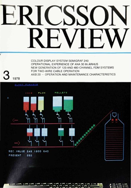
COVER<br />
<strong>The</strong> colour display system <strong>SEMIGRAF</strong> <strong>240</strong>, developed<br />
by SRA Communications AB, a member <strong>of</strong><br />
the <strong>Ericsson</strong> Group, replaces a conventional<br />
control panel. <strong>The</strong> cover shows a schematic picture<br />
<strong>of</strong> the operational state <strong>of</strong> a blast furnace.
<strong>Colour</strong> <strong>Display</strong> <strong>System</strong><br />
<strong>SEMIGRAF</strong> <strong>240</strong><br />
Bjorn Karbeus<br />
This article presents the new computerized colour display system <strong>SEMIGRAF</strong> <strong>240</strong>.<br />
which replaces conventional types <strong>of</strong> control panels. <strong>SEMIGRAF</strong> <strong>240</strong> has been<br />
developed by SRA Communications AB, a member <strong>of</strong> the <strong>Ericsson</strong> Group.<br />
UDC681 326:<br />
621.397 132<br />
Fig. 1<br />
Control room with display units that form the<br />
opera tor pane I for control <strong>of</strong> an ore dressing plant<br />
<strong>The</strong> transition from the earlier manual<br />
control and supervisory systems <strong>of</strong> various<br />
types to computerized systems<br />
makes new demands on the units that<br />
transfer orders and information between<br />
operator and system.<br />
For a long time various types <strong>of</strong> control<br />
panels with instruments, switches and<br />
controls provided the normal solution.<br />
In large systems such control panels can<br />
be very extensive, and can sometimes<br />
take up a whole wall. <strong>The</strong>y are therefore<br />
expensive and difficult to change. An<br />
improvement was achieved by introducing<br />
various types <strong>of</strong> black/white graphic<br />
displays as operator units. <strong>The</strong> operator<br />
could then fetch information from the<br />
system, and also control it by feeding in<br />
various commands. However, in many<br />
cases it proved to be difficult for an<br />
operator to assimilate the displayed information<br />
quickly and correctly. <strong>The</strong> introduction<br />
<strong>of</strong> colour as an aid in the<br />
structurization <strong>of</strong> the displayed pictures<br />
made it very much easier to recognise<br />
and understand the information shown.<br />
Background<br />
SRA Communications AB have worked<br />
on different types <strong>of</strong> displays, both<br />
black/white and colour since 1969.<br />
<strong>SEMIGRAF</strong> is the registered trade mark<br />
for colour display systems manufactured<br />
by SRA.<br />
<strong>The</strong> first system, designed <strong>SEMIGRAF</strong><br />
210, was delivered in 1974 and since<br />
then many systems have been supplied<br />
for a number <strong>of</strong> different applications,<br />
such as power supervision, ore dressing,<br />
railway control and supervision <strong>of</strong><br />
coaxial cable networks.
BJORN KARBEUS<br />
SRA Communications AB<br />
To the<br />
computer<br />
Fig. 2<br />
A <strong>SEMIGRAF</strong> system consists primarily <strong>of</strong> a control<br />
unit, colour TV and keyboard. A light-pen can<br />
be added as an accessory for interactive work with<br />
the display.<br />
A picture is stored and generated in the control<br />
unit tor display on the colour monitor. Signals representing<br />
red, green and blue beams and for<br />
synchronization go from the control unit to the colour<br />
monitor. Input takes place via a keyboard<br />
Fig. 3<br />
<strong>The</strong> control unit is the central unit for picture generation.<br />
<strong>The</strong> picture to be displayed is stored in the<br />
picture store. <strong>The</strong> character generator interprets<br />
the content ot the picture store and generates the<br />
characters to be displayed on the screen.<br />
<strong>The</strong> video unit converts the digital signals to<br />
analog signals for operating the colour monitor.<br />
<strong>The</strong> time base generates timing and control signals<br />
for the various parts <strong>of</strong> the control unit.<br />
<strong>The</strong> 8-bit processor is the administrative unit,<br />
which via the I/O unit handles the communication<br />
with the keyboard and the main computer<br />
<strong>Display</strong><br />
<strong>SEMIGRAF</strong> <strong>240</strong> is the newest member <strong>of</strong><br />
the <strong>SEMIGRAF</strong> family. Utilization <strong>of</strong> the<br />
new integrated circuits, which have become<br />
available during the last few years<br />
as a result <strong>of</strong> the great advances in<br />
semiconductor technology, has made<br />
Keyboard<br />
87<br />
possible the design <strong>of</strong> an equipment<br />
with a performance which only a few<br />
years ago could hardly have been attained<br />
within a limited framework.<br />
A <strong>SEMIGRAF</strong> <strong>240</strong> system consists <strong>of</strong> a<br />
varying number <strong>of</strong> units depending on<br />
the application, fig. 2.
88<br />
Fig. 4<br />
<strong>The</strong> three beams red, green and blue sweep in a<br />
fixed pattern over the screen. <strong>The</strong> desired picture<br />
is obtained by means <strong>of</strong> intensity modulation<br />
Fig. 5<br />
<strong>The</strong> picture is built up ot characters, which are<br />
generated in matrix form. <strong>The</strong>re are two types <strong>of</strong><br />
characters, alphanumeric (letters, figures and<br />
punctuation marks) and graphic (lines, corners,<br />
squares etc.)<br />
<strong>The</strong> control unit is the central unit in<br />
which the displayed picture is generated.<br />
A block diagram is shown in fig. 3.<br />
<strong>The</strong> control unit has a modular structure<br />
and can thus be adapted to different<br />
display requirements. Starting with a<br />
basic unit extra functions can be added<br />
to give the desired overall function.<br />
<strong>The</strong> picture is displayed using the raster<br />
method, i.e. the picture is drawn by<br />
means <strong>of</strong> intensity modulation <strong>of</strong> three<br />
beams (Red, Green and Blue), which<br />
sweep in a fixed pattern over the surface<br />
<strong>of</strong> the colour monitor all the time, fig. 4.<br />
Inside the glass surface <strong>of</strong> the colour<br />
monitor there is a pattern <strong>of</strong> red, green<br />
and blue phosphorus dots. By means <strong>of</strong><br />
intensity modulation the different<br />
phosphorus dots can be made to light in<br />
a desired pattern so that the picture<br />
stored in the picture store <strong>of</strong> the control<br />
unit appears on the screen.<br />
<strong>The</strong> beams sweep over the screen so<br />
that a complete scan takes 20 ms. Every<br />
picture is drawn in exactly the same<br />
tracks. In this respect it differs from a<br />
normal TV system, which works with<br />
odd and even fields. Since all fields are<br />
the same, a true 50 Hz picture frequency<br />
is obtained and the 25 Hz flicker<br />
obtained in an ordinary TV system is<br />
avoided. This gives a picture that is<br />
practically free from flicker.<br />
<strong>The</strong> screen can be imagined as being<br />
divided into a grid with squares in rows<br />
and columns. In each square - character<br />
position - one character can bewrit-<br />
ten. <strong>The</strong> characters are divided into two<br />
categories, alphanumeric characters<br />
(letters, figures and punctuation marks)<br />
and graphic characters (lines, corners,<br />
rectangles and other symbols) which<br />
are used to build up the graphic information,<br />
fig. 5.<br />
<strong>The</strong> displayed picture is stored in a<br />
picture store with capacity for one or<br />
four pictures. <strong>The</strong>re is a place reserved<br />
in the picture store for each character<br />
position on the screen. Each place in the<br />
memory has a maximum length <strong>of</strong> 20<br />
bits. <strong>The</strong>se bits give the character to be<br />
displayed and the colour and whether<br />
blinking is available or not. Thus each<br />
individual character that is displayed<br />
has its own colour information stored.<br />
Each character is allocated two colours,<br />
a foreground colour, which is the colour<br />
<strong>of</strong> the symbol itself, and a background<br />
colour, for the remainder <strong>of</strong> the character<br />
position when it is displayed, fig. 6.<br />
<strong>The</strong> content <strong>of</strong> the picture store is read<br />
out concurrently with the sweep <strong>of</strong> the<br />
beams (R, G, B) over the screen. <strong>The</strong><br />
time base controls the various time<br />
sequences. <strong>The</strong> synchronization signal<br />
S makes the monitor work in synchronism<br />
with the control unit. <strong>The</strong> information<br />
read out from the picture store only<br />
indicates which character is to be displayed<br />
at a certain moment, not the<br />
actual shape <strong>of</strong> the character. <strong>The</strong> latter<br />
information is provided by the character<br />
generator, which contains descriptions<br />
<strong>of</strong> all the different characters that can be<br />
generated <strong>The</strong> character generator<br />
permits the display <strong>of</strong> two sizes <strong>of</strong>
Fig. 6<br />
Each character position is associated with two<br />
colours, the foreground colour, which is the colour<br />
<strong>of</strong> the character itself, and the background colour,<br />
which is displayed in the remainder <strong>of</strong> the character<br />
position<br />
Fig. 7<br />
Schematic picture <strong>of</strong> a digester for wood pulp<br />
characters. <strong>The</strong> two character sizes can<br />
be combined as desired.<br />
Storing a new picture<br />
So far the article has described briefly<br />
how a new picture, which lies ready in<br />
the picture store, is drawn on the<br />
monitor screen, but not how a new<br />
picture is generated and stored in the<br />
picture store.<br />
A picture in the picture store is generated<br />
either from the keyboard or from a<br />
main computer, or from a combination<br />
<strong>of</strong> the two.<br />
When a picture is built up from the<br />
keyboard the visible cursor is used,<br />
which is a white blinking symbol consisting<br />
<strong>of</strong> two horizontal lines. <strong>The</strong> size<br />
<strong>of</strong> the cursor is exactly that <strong>of</strong> a character<br />
position, and it indicates to the<br />
operator the spot on the screen where<br />
the next character to be written will be<br />
placed. <strong>The</strong> cursor can be moved about<br />
on the screen with special keys in the<br />
keyboard.<br />
<strong>The</strong> following parameters can be<br />
specified before a character is written<br />
on the screen:<br />
— Foreground colour<br />
— Background colour<br />
— Blinking or not<br />
— Character set (alphabet)<br />
89<br />
All characters that are then written will<br />
have the status specified in accordance<br />
with the above until another status is<br />
specified.<br />
When the voltage for the control unit is<br />
switched on, white foreground colour<br />
on a black background is automatically<br />
set up and the alphanumeric character<br />
set is selected. <strong>The</strong> operator can then<br />
specify the desired colour, blink etc. before<br />
writing any characters on the<br />
screen.<br />
<strong>The</strong> characters that are written on the<br />
screen are stored in character stores<br />
which can be <strong>of</strong> two types: PROMs and<br />
read/write memories (RAM).<br />
Characters stored in a PROM cannot be<br />
altered unless the memory elements are<br />
removed and replaced by new ones,<br />
programmed with a new set <strong>of</strong><br />
characters. Characters stored in a<br />
PROM are preserved even when the<br />
voltage is switched <strong>of</strong>f.
90<br />
Fig. 8<br />
Keyboard for <strong>SEMIGRAF</strong> <strong>240</strong> with individual power<br />
feeding. <strong>The</strong> communication with the control unit<br />
is carried outin series form via opto-insulated current<br />
sections. <strong>The</strong>re are built-in circuits for acoustic<br />
alarm (bell).<br />
<strong>The</strong> read/write memory for character<br />
storage enables characters with<br />
arbitrary shapes, within the limits <strong>of</strong> the<br />
character matrix, to be programmed in<br />
from a main computer or from the<br />
keyboard. Characters stored in the<br />
read/write memory are lost when the<br />
voltage to the control unit is switched<br />
<strong>of</strong>f, and must be programmed in again<br />
when starting up.<br />
<strong>The</strong> building up <strong>of</strong> new characters for a<br />
user-oriented character range is simplified<br />
by the built-in interactive routine for<br />
creating new characters with the aid <strong>of</strong><br />
the keyboard.<br />
When a new character is to be built up<br />
this routine is started by depressing a<br />
key on the keyboard. A frame is then<br />
displayed on the screen, within which<br />
the character is shown magnified during<br />
the building-up process. A cursor can<br />
then be moved within the frame and<br />
each point in the character matrix can<br />
be specified as foreground or background.<br />
When the character matrix has<br />
been built up as desired, the character<br />
can be stored in the character store under<br />
the desired name. <strong>The</strong> programmed<br />
character can then be written on the<br />
screen and thereby checked that it is<br />
correct. If the operator is not satisfied<br />
with a certain character it can be returned<br />
to the programming frame, cor<br />
rected and then finally stored again.<br />
A set <strong>of</strong> characters that has been built up<br />
in this way can be read into the main<br />
computer by means <strong>of</strong> a special command<br />
and stored there in a bulk store.<br />
When the system is started up, or when a<br />
new set <strong>of</strong> characters is required, the<br />
character store can then be loaded with<br />
the desired set.<br />
Keyboard<br />
<strong>The</strong> keyboard for <strong>SEMIGRAF</strong> <strong>240</strong> has<br />
been specially designed so that it can be<br />
placed a long way away from the control<br />
unit.<br />
<strong>The</strong> keyboard has its own power supply<br />
and when installed is connected to the<br />
nearest wall socket. Communication between<br />
the keyboard and the control unit<br />
takes place via a cable with four conductors.<br />
<strong>The</strong> character codes have a<br />
length <strong>of</strong> 8 bits and are sent from the<br />
keyboard in series form at a signalling<br />
speed <strong>of</strong> 300 Baud. <strong>The</strong> keyboard contains<br />
a locking key with which the<br />
operator can signal to the control unit<br />
when it is to be on-line. <strong>The</strong> keyboard<br />
also contains a bell which can be activated<br />
from the control unit. All communication<br />
to and from the keyboard<br />
takes place with current loops <strong>of</strong> 20 mA.
Fig. 9, left<br />
<strong>The</strong> control unit consists <strong>of</strong> a 19 printed board unit<br />
with built-in power supply<br />
Fig. 10<br />
<strong>The</strong> processor board, CPU, is a complete eight-bit<br />
computer with central processing unit, program<br />
store, data store, vectorial break logic and two interfaces<br />
in series<br />
Communication with<br />
a main computer<br />
<strong>The</strong> control unit can communicate with<br />
a main computer in parallel or series<br />
form. <strong>The</strong> standard version has a series<br />
channel in accordance with CCITT V24<br />
in full duplex and the transmission<br />
speed is switchable between 110 and<br />
9600 Baud. <strong>The</strong> transmission is carried<br />
out either with or without parity check.<br />
Transmission with parity check is carried<br />
out in blocks with a maximum<br />
length <strong>of</strong> 128 bytes, each block starting<br />
with STX and finishing with ETX.<br />
Any type <strong>of</strong> parallel connection may be<br />
used, the choice depending only on the<br />
type <strong>of</strong> computer to which the control<br />
unit is to be connected.<br />
Division into hardware<br />
and s<strong>of</strong>tware<br />
<strong>The</strong> functions <strong>of</strong> the control unit can be<br />
divided into two groups:<br />
a. the control <strong>of</strong> the colour monitor,<br />
which is tied to the timing sequence<br />
b. other functions.<br />
<strong>The</strong> direct drawing <strong>of</strong> the picture on the<br />
colour monitor is a fast process that<br />
must be repeated regularly in order to<br />
maintain the picture on the screen. All<br />
the direct picture drawing on the screen<br />
is implemented in hardware.<br />
<strong>The</strong> 8-bit microprocessor included in<br />
the control unit is quite unable to operate<br />
at the speeds required to carry out<br />
the direct picture drawing, since each<br />
raster point in a picture has a time dimension<br />
<strong>of</strong> only about 100 nanoseconds.<br />
<strong>The</strong> tasks <strong>of</strong> the processor are:<br />
— to handle the communication with a<br />
main computer via the computer input<br />
and output devices<br />
— to handle the communication with<br />
the keyboard via the keyboard input<br />
and output devices<br />
— to interpret the character sequences<br />
received from keyboard and computer<br />
and to carry out the requested<br />
functions<br />
— to write in external information in the<br />
picture store<br />
— to write in the character store<br />
— to move information in the picture<br />
store (editing)<br />
— to fetch information from the picture<br />
store or character store and send it to<br />
the main computer (e.g. "read line").<br />
Many functions are thus carried out or<br />
controlled by s<strong>of</strong>tware, which gives a<br />
unit that can easily be adapted to special<br />
application requirements.<br />
It has also been possible to adapt the<br />
system to the users — human beings —<br />
and at the same timeto arrange efficient<br />
means <strong>of</strong> communication with a main<br />
computer.
Operational Experience<br />
<strong>of</strong> ANA 30 in Arhus<br />
Henning Kortsen and Christian Neergaard-Petersen<br />
An article in a previous issue <strong>of</strong> <strong>Ericsson</strong> Review described how the Jutland<br />
Telephone Company, Jydsk Telefon A/S or JTAS, Denmark, was modernizing its<br />
crossbar exchanges ARF 10 by converting them to ARE 11 exchanges with the aid<br />
<strong>of</strong> the control system ANA 30\ This applies for the whole <strong>of</strong> the Arhus exchange<br />
area. <strong>The</strong> new exchanges <strong>of</strong>fer better traffic routing and operational supervision<br />
possibilities and also sa vings as regards personnel. It is also possible to improve the<br />
service to the subscribers in the form <strong>of</strong> new facilities and traffic possibilities.<br />
In this article the results <strong>of</strong> the operational experience from Arhus are described,<br />
and the associated questions regarding organisation, reduced personnel requirement<br />
and training are discussed. However, since the modernization is still in progress,<br />
with ANA 30 now being installed in the exchanges in the city suburbs, it is<br />
only possible to present the operational results <strong>of</strong> ARE 11 in Arhus Centrum, the<br />
main exchange with 25 000 lines which has been in operation during the whole <strong>of</strong><br />
1977. This exchange also contains the operating centre for the whole zone.<br />
UDC 621.395.722<br />
Fig. 1<br />
<strong>The</strong> Arhus operating centre and the manned and<br />
unmanned exchanges in the Arhus exchange area<br />
O Manned exchange<br />
• Unmanned exchange<br />
Organisation<br />
<strong>The</strong> Arhus operating centre is a common<br />
unit <strong>of</strong> great importance to all exchanges<br />
in the area. From there it is<br />
possible to inform about operating conditions,<br />
assist in the clearing <strong>of</strong> serious<br />
faults, carry out changes <strong>of</strong> subscriber<br />
category and provide a number <strong>of</strong> other<br />
essential services.<br />
After the modernization five <strong>of</strong> the thirteen<br />
local exchanges in Arhus will be<br />
manned, fig. 1. (Whether an exchange is<br />
manned or not is determined on the<br />
basis <strong>of</strong> size and position.) <strong>The</strong> associated<br />
five maintenance areas are<br />
each managed by a chief engineer, who<br />
reports to a main-<strong>of</strong>fice manager.<br />
If assistance is needed for a complicated<br />
fault the area concerned turns direct to<br />
the operating centre. <strong>The</strong> reguired assistance<br />
can be given via a teleprinter or<br />
display unit, fig. 2.<br />
In the operating centre the category<br />
allocation <strong>of</strong> each subscriber in the<br />
whole area is written into the subscriber<br />
category memory with a teleprinter, fig.<br />
3. This is done for all categories except<br />
the interception service category, which<br />
is written in by the interception<br />
operators, who are placed in a special<br />
room (the switchboard room).<br />
All external applications, including fault<br />
reports, are routed to the operating<br />
centre. All alarms from the local exchanges<br />
and the 30 rural automatic exchanges<br />
in the area are also taken in to<br />
the centre.<br />
Any alarms outside working hours are<br />
connected to the switchboard room,<br />
where an operator calls a repairman<br />
when necessary. It is then advantageous<br />
that all exchanges in the area can be<br />
controlled from the operating centre.<br />
<strong>The</strong> operating centre is always kept in-
HENNING KORTSEN<br />
CHRISTIAN NEERGAARD-PETERSEN<br />
Jydsk Telefon A/S<br />
Arhus, Denmark<br />
Table 1<br />
Number <strong>of</strong> faults during 1 year in ANA 30,<br />
Arhus Centrum<br />
1<br />
Type <strong>of</strong> device ?o ?f<br />
' faults<br />
Traffic control processor, TCP 4<br />
Multiplexor. MUX") 2<br />
Translation store. TRS 3<br />
Code receiver for tone frequencies,<br />
KMK 4<br />
Code receiver, KM 3<br />
Signal transfer unit for SR, STU-L 3<br />
Signal transfer unit for FIR, STU-I 3<br />
Identification unit for GV, IDG 1<br />
Total 23<br />
*) Each processor is connected to a duplicated multiplexor<br />
in each rack that contains mterworking devices.<br />
MUX ensures that only one processor at a time is connected<br />
to any device in the rack in question<br />
Table 2<br />
<strong>The</strong> distribution <strong>of</strong> the faults among different<br />
groups <strong>of</strong> equipment<br />
Number <strong>of</strong> Per-<br />
Fault source faults per cent-<br />
10 000 lines age<br />
Control system ANA 30 9 2 0 2<br />
REG-L in the former<br />
ARF 100registerequipment (510) (1.1)<br />
Switching system (ARF100) 320 6 9<br />
Subscriber lines and<br />
telephone sets 4300 92.9<br />
Fig. 2<br />
<strong>The</strong> operating centre provides assistance with<br />
the analysis <strong>of</strong> a fault<br />
formed <strong>of</strong> the whereabouts <strong>of</strong> each repairman.<br />
It is <strong>of</strong> great value to be able to<br />
contact each individual repairman from<br />
the operating centre.<br />
A common spare part store for the five<br />
maintenance centres has been set up at<br />
the operating centre. Defective printed<br />
board assemblies are sent from the<br />
centre to LM <strong>Ericsson</strong>'s workshop in<br />
Copenhagen for repair.<br />
For the time being all communication<br />
between the exchanges and the operating<br />
centre or the switchboard room<br />
takes place via telephone circuits, which<br />
are connected up through the public<br />
telephone network to modems connected<br />
in the exchanges in question.<br />
Operational statistics<br />
After a running-in period the operational<br />
statistics for exchanges with control<br />
system ANA 30 show that the number <strong>of</strong><br />
faults and serious operational disturbances<br />
has been greatly reduced.<br />
<strong>The</strong> trunking diagram <strong>of</strong> fig. 4 shows an<br />
ARF 100 exchange in Arhus which has<br />
been modernized with control system<br />
ANA 30.<br />
93<br />
three processor groups, 23 faults occurred<br />
in the ANA 30 equipment during the<br />
whole <strong>of</strong> 1977. Table 1 shows the faults<br />
distributed among types <strong>of</strong> devices.<br />
21 <strong>of</strong> the faults were routine faults and<br />
did not disturb the traffic handling, but<br />
two caused serious operational disturbances,<br />
particularly as they occurred<br />
during the busy hour. One fault resulted<br />
in the breakdown <strong>of</strong> a traffic control<br />
processor TCP, and the other in the<br />
malfunctioning <strong>of</strong> a multiplexor, MUX.<br />
<strong>The</strong> operational disturbances occurred<br />
because faults occurred in the automatic<br />
changeover to the standby units at<br />
the same time.<br />
In order to illustrate the fault distribution<br />
table 2 has been prepared, showing the<br />
different categories <strong>of</strong> faults that occurred<br />
in the 25-year old local exchange in<br />
Arhus during one year. Values available<br />
for the earlier crossbar registers REG-L<br />
have been given in brackets to facilitate<br />
a comparison between ANA 30 and<br />
REG-L.<br />
When the above results are compared it<br />
should be remembered that ANA 30 has<br />
more sophisticated traffic characteristics<br />
than the old ARF 100 registers.<br />
In Arhus Centrum, with 25 000 lines and <strong>The</strong> operator is notified <strong>of</strong> faults in con-
94<br />
Fig. 3<br />
Changing subscriber categories from the<br />
operating centre<br />
trol system ANA 30 by means <strong>of</strong> alarms<br />
and printouts administered by the operation<br />
and maintenance processor,<br />
OMP.<br />
Faults in the switching system can also<br />
be found with the aid <strong>of</strong> ANA 30, since its<br />
printouts show the switching processes<br />
in the form <strong>of</strong> digits and control signals.<br />
Other printouts specify the device<br />
groups that exceed the permitted error<br />
level limits (STU, KS, KM). <strong>The</strong>se printouts<br />
can indicate faults in the switching<br />
system and the network.<br />
After the introduction <strong>of</strong> ANA 30 it has<br />
also been possibleto keep the switching<br />
system in better condition than before,<br />
since the latter system has gradually<br />
been adjusted to the exacting signalling<br />
and time conditions that apply for<br />
ANA 30.<br />
In spite <strong>of</strong> the fact that ANA 30 gives detailed<br />
fault information, the supplementary<br />
fault reports from the subscribers<br />
are <strong>of</strong> importance, for example<br />
when there is a fault in the signal reception<br />
from the push-button sets.<br />
Experience from ANA 30 in Arhus<br />
Centrum shows that after a running-in<br />
period the system is very reliable. <strong>The</strong><br />
operational statistics show that the duplication<br />
<strong>of</strong> most <strong>of</strong> the function units in<br />
ANA 30 ensures that large operational<br />
disturbances are to all intents and<br />
purposes eliminated.<br />
Saving in personnel<br />
By the middle <strong>of</strong> 1978 115 000 lines in<br />
the Arhus area were connected to<br />
ARE 11 exchanges with ANA 30. If these<br />
subscribers were to have been served by<br />
ARF 100 instead, 21 technicians would<br />
have been required for the operation<br />
and maintenance <strong>of</strong> the exchanges, not<br />
including the MDF staff.<br />
It is estimated that after the modernization<br />
with ANA 30 the number <strong>of</strong> technicians<br />
required will be reduced to 18, a<br />
saving <strong>of</strong> 3. Furthermore it is expected<br />
that the staff will be kept at this number<br />
during the coming years despite the fact<br />
that the number <strong>of</strong> subscribers is expected<br />
to increase by 8 % annually.<br />
In addition there is a saving <strong>of</strong> 1/2 man<br />
year per year because such administrative<br />
tasks as category changes, route<br />
changes etc. are carried out by means <strong>of</strong><br />
commands.
Fig. 4<br />
Tmnking diagram with ARF 100 in Arhus,<br />
modernized by the addition <strong>of</strong> control system<br />
ANA 30 to ARE 11<br />
SLM Subscriber stage marker<br />
GVM Group selector marker<br />
IDS Identification unit for A-subscriber<br />
STU-L Signal transfer unit for SR (SR - cord line relay<br />
set)<br />
STU-I Signal transfer unit for FIR (FIR - junction<br />
line relay set)<br />
SS Code sender finder<br />
KMK Code receiver tor tone frequencies<br />
KS-MFC Code sender lor MFC<br />
GV-KME Matching unit for group selectors<br />
IDG Identification unit<br />
KM-MFC Code receiver tor MFC<br />
TCP Traffic control processor<br />
OMP Operation and maintenance processor<br />
SCS Subscriber category store<br />
TRS Translation store<br />
ADS Abbreviated dialling store<br />
Just the disconnection and reconnection<br />
<strong>of</strong> bad payers by command saves<br />
1/3 man year per year among the MDF<br />
staff.<br />
Even though a saving in personnel is<br />
important this is not the main purpose <strong>of</strong><br />
the modernization. <strong>The</strong> main objective<br />
is to obtain a system that <strong>of</strong>fers many<br />
new facilities and services and which<br />
can later be equipped with still more, for<br />
example common channel signalling 2 .<br />
Training<br />
On the basis <strong>of</strong> the experience gained<br />
hitherto the training requirements can<br />
be described as follows. Technicians<br />
with electromechanical training should<br />
attend a basic course, after which they<br />
can handle the exchange and repair<br />
common faults. This basic course<br />
should include the following subjects:<br />
1. Binary and hexadecimal<br />
number systems<br />
2. Basic system knowledge<br />
3. <strong>System</strong> structure<br />
4. <strong>The</strong> traffic control processor,<br />
TCP<br />
5. <strong>The</strong> operation and maintenance<br />
processor, OMP<br />
IIGV<br />
KS-MFC IDG<br />
7 hrs<br />
4 ,,<br />
3 ,,<br />
14 ,,<br />
14 ,,<br />
95<br />
6. Commands 21 ,,<br />
7. Subscriber category store,<br />
SCS 7 ,,<br />
8. Translation store, TRS 10 ,,<br />
9. Signal transfer units,<br />
STU-L and STU-I 4 ,,<br />
10. Traffic recording and<br />
statistics 7 ,,<br />
11. Flow charts and program<br />
knowledge 14 ,,<br />
12. Operating a processor panel 7 ,,<br />
13. Fault tracing 14 ,,<br />
14. Exchange tester 14 ,,<br />
Total 140 hrs<br />
After a year's work with the system, exfended<br />
ANA 30 training can suitably be<br />
provided to give a more detailed insight<br />
into the problems. Such a course, which<br />
would enable the technician to handle<br />
difficult fault clearing problems, could<br />
include the following:<br />
1. Microcomputer course 24 hrs<br />
2. Processor APN 110, theory 24 ,,<br />
3. Program knowledge 48 ,,<br />
4. TRS, build-up 4 ,,<br />
5. TRS, data 28 ,,<br />
6. APN 110, build-up 24 ,,<br />
7. Multiplexor, MUX 8 ,,<br />
8. Identifier for GV, IDS 8 ,,<br />
9. TRS-SCS 16 ,,<br />
10. <strong>The</strong> operating manual 8 ,,<br />
11. Follow-up 8 ,,<br />
Total 200 hrs<br />
Together, these courses provide a<br />
sound syllabus. <strong>The</strong> personnel are free<br />
to attend the extended course or not.<br />
Even though it may not be actually<br />
necessary to train all personnel the<br />
costs involved are small and it helps to<br />
maintain the interest and sense <strong>of</strong> responsibility<br />
<strong>of</strong> the personnel.<br />
In 1978 an extended course for 6 technicians<br />
will be arranged in Arhus.<br />
References<br />
LMeland, F. and Rishoj, E.: Crossbar<br />
Exchanges in Arhus Become<br />
SPC Exchanges. <strong>Ericsson</strong> Rev. 54<br />
(1977):2, pp. 86-89.<br />
2. Andersen, H. and Pedersen, V.K.:<br />
Field Trial with Common Channel<br />
Signalling. <strong>Ericsson</strong> Rev. 55 (1978):<br />
1, pp. 20-27.
New Generation <strong>of</strong> 120 and<br />
480-Channel FDM <strong>System</strong>s<br />
for Two-Wire Cable Operation<br />
Per-Erik Johansson<br />
<strong>System</strong>s ZAX-ZAC 120 T and ZAX-ZAC 480 T utilize one cable pair jointly for both<br />
directions <strong>of</strong> transmission. <strong>The</strong> systems are intended for single-tube coaxial cables<br />
and for increasing the capacity <strong>of</strong> existing twin cable networks. <strong>The</strong>re is also an<br />
extensive range <strong>of</strong> branching eguipment available for these systems, and they are<br />
thus well suited not only for public telecommunications networks but also for military<br />
networks and power, railway and pipeline projects.<br />
<strong>The</strong> earlier generation <strong>of</strong> this system was introduced at the end <strong>of</strong> the 1960s, and<br />
sincethen morethan 13 000 kilometres <strong>of</strong> the system have been installed on various<br />
types <strong>of</strong> cable in widely diverging climatic conditions.<br />
<strong>The</strong> article describes briefly the experience gained from the first generation <strong>of</strong> the<br />
line equipment for two-wire operation over small-core coaxial cable, ZAX 120 T\<br />
and also the main technical features <strong>of</strong> the new systems.<br />
UDC 621 395.4<br />
621.315.212<br />
Fig. 1<br />
Installation testing <strong>of</strong> ZAC 120 T equipment for the<br />
Swedish State Railways<br />
Experience from the earlier<br />
system generation<br />
<strong>The</strong> experience from the first generation<br />
<strong>of</strong> 2-wire systems, ZAX 120 T, can in all<br />
essential respects be considered as very<br />
good. When ZAX 120T was introduced it<br />
was the aim to <strong>of</strong>fer a system alternative,<br />
based on single-tube coaxial pairs for<br />
mounting on existing poles, which<br />
could be used instead <strong>of</strong>, for example,<br />
12-channel aerial line systems.<br />
<strong>The</strong> fears that an aerial coaxial cable<br />
would be subjected to cable breaks<br />
more <strong>of</strong>ten than a buried cable have<br />
proved to be unfounded. It has been<br />
established, however, that the cable<br />
must be robust in order to withstand<br />
rough handling during installation, and<br />
the stresses caused by strong winds,<br />
so-called galloping, which can occur in<br />
open terrain. Another important reguirement<br />
is that the cable has good<br />
screening against external interference<br />
from, for example, MW transmitters.<br />
This means that the coaxial tube should<br />
be provided with a magnetic screen and<br />
a surrounding conducting layer <strong>of</strong><br />
aluminium or a similar material.<br />
LM <strong>Ericsson</strong>'s single-tube coaxial cables<br />
were modified at an early stage<br />
when the area <strong>of</strong> the suspension wire<br />
was increased and an aluminium screen<br />
was introduced.<br />
<strong>The</strong> method originally chosen for fault<br />
location <strong>of</strong> cable breaks was found to be<br />
not wholly reliable in areas where<br />
thunderstorms occur frequently. A modification<br />
was therefore introduced<br />
whereby a shunt resistor was fitted in<br />
each amplifier in the power feeding<br />
path. If a cable break occurs the fault is<br />
located by reading <strong>of</strong>f the summed feeding<br />
current on an instrument that is<br />
graduated direct in number <strong>of</strong> stations<br />
up to the fault. Since the modification<br />
the location <strong>of</strong> cable breaks has functioned<br />
quite satisfactorily.<br />
<strong>The</strong> check and test points etc., which as<br />
a precautionary measure had been<br />
specified for the buried equipment,<br />
proved to be unnecessarily extensive.<br />
<strong>The</strong> experience gained from ZAX 120 T<br />
is similar to that <strong>of</strong> conventional large<br />
coaxial cable systems. <strong>The</strong> most com-
PER-ERIK JOHANSSON<br />
Transmission Division<br />
Telefonaktiebolaget LM <strong>Ericsson</strong><br />
Fig. 2<br />
Line repeater tor ZAX-2AC 480 T, seen trom two<br />
directions. <strong>The</strong> unit contains all electronic equipment<br />
for a dependent repeater station. <strong>The</strong> power<br />
separation filter and directional filters are shown<br />
on the left. On the right are the fault location oscillator,<br />
the amplifier and the pilot receiver<br />
mon cause <strong>of</strong> traffic disturbances is<br />
damage to the cable, not faults in the<br />
electronic equipment.<br />
During the last ten years the system has<br />
been put into operation in a number <strong>of</strong><br />
different applications. <strong>The</strong> frequency<br />
allocation plan used, in accordance with<br />
CCITT G 356, 1A, has made possible direct<br />
through-connection to larger<br />
systems and has also been advantageous<br />
when arranging various forms <strong>of</strong><br />
leak branching stations. <strong>The</strong> possibility<br />
<strong>of</strong> carrying out small leak branchings<br />
along a line on a group basis has also<br />
been <strong>of</strong> particular interest.<br />
Among the military applications can be<br />
mentioned a special arrangement for<br />
line networks, whereby automatic<br />
changeover to standby routes maintains<br />
full capacity between the leak branching<br />
stations included in the system, even if<br />
the cable on the first-choice route<br />
should be damaged.<br />
<strong>The</strong> line repeaters have pilot regulation,<br />
which is necessary because different<br />
sections <strong>of</strong> the cable may be run in different<br />
ways, for example in air, buried or<br />
laid in ducts, and are thus subjected to<br />
extremely varying temperature conditions.<br />
<strong>The</strong> regulation range <strong>of</strong> ±4 dB at<br />
the pilot frequency has proved to be suf<br />
ficient for all climatic regions.<br />
97<br />
In order to meet a growing need to be<br />
able to increase the traffic capacity <strong>of</strong><br />
existing twin cables through the introduction<br />
<strong>of</strong> modern carrier systems with<br />
more than 12 channels, the equipment<br />
was also adapted for use with that type<br />
<strong>of</strong> cable. <strong>The</strong> transmission characteristics<br />
<strong>of</strong> paper insulated twin cables have<br />
been determined by means <strong>of</strong> extensive<br />
field measurements and theoretical<br />
studies 2 . <strong>The</strong> system has proved to be<br />
very suitable for use on such cables, and<br />
has made it possible to increase the<br />
capacity many times over without laying<br />
new cables, at only the relatively low<br />
cost for the electronic equipment.<br />
<strong>The</strong> system is designed so that a changeover<br />
from coaxial cables to twin cables<br />
is possible without termination or<br />
division into separate pilot sections.<br />
<strong>The</strong> equipment installed for the Swedish<br />
State Railways constitutes an example<br />
<strong>of</strong> a countrywide network for 120 channels<br />
on twin cables. Further extensions<br />
<strong>of</strong> this network are planned. <strong>The</strong> cables<br />
used, which were installed as long ago<br />
as the 1920s, consist <strong>of</strong> lead-sheathed<br />
paper insulated twin and quad cables<br />
with 0.9-1.3 mm conductors. <strong>The</strong> extensions<br />
will also include coaxial cables.
98<br />
Fig. 3<br />
Translation <strong>of</strong> basic supergroups to a 480-channel<br />
line group<br />
General principles for<br />
the new generation<br />
<strong>of</strong> systems<br />
<strong>The</strong> systems comprise two equipments<br />
designated ZAX-ZAC 120 T and ZAX-<br />
ZAC 480 T. <strong>The</strong> designation ZAX-T<br />
means equipment for two-wire transmission<br />
via a coaxial cable and ZAC-T<br />
the corresponding equipment for symmetrical<br />
twin cable. <strong>The</strong> transmission<br />
capacities are 120 and 480 telephone<br />
channels respectively.<br />
<strong>The</strong> guiding principles for the new development<br />
have been based partly on<br />
experience from the first generation <strong>of</strong><br />
two-wire systems and partly on the<br />
technical innovations incorporated in<br />
the design <strong>of</strong> the latest versions <strong>of</strong><br />
four-wire systems, ZAX 960-9 and ZAX<br />
2700-4 4 .<br />
<strong>The</strong> basic principles can be summarized<br />
as follows:<br />
- the line repeaters are constructed in<br />
accordance with the principle applied<br />
for submarine cable systems,<br />
with a common repeater for both directions<br />
<strong>of</strong> transmission<br />
— the line group is always obtained in<br />
its basic position at the interface between<br />
the multiplex equipment and<br />
the line group equipment<br />
— the line group modulation frequency<br />
is transmitted to the other terminal or<br />
branching station for regeneration<br />
and to provide full synchronization<br />
between the stations<br />
- the same frequency is used for the<br />
line pilot and the modulation <strong>of</strong> the<br />
line group<br />
- automatic level regulation <strong>of</strong> the line<br />
amplifiers is carried out using the line<br />
pilot<br />
- cable faults are located with the aid <strong>of</strong><br />
the remote power feeding.<br />
On the basis <strong>of</strong> these principles systems<br />
ZAX-ZAC 120 T and ZAX-ZAC 480 T have<br />
been developed to meet the varying demands<br />
<strong>of</strong> a diverse market. Some such<br />
demands are: long power feeding sections,<br />
the possibility <strong>of</strong> selective<br />
monitoring <strong>of</strong> line repeaters, several<br />
variants <strong>of</strong> leak branching and adaption<br />
to longer regulation sections on symmetrical<br />
twin cables. Some <strong>of</strong> these improvements<br />
are based on solutions<br />
already applied in corresponding 4-wire<br />
cable systems.<br />
<strong>The</strong> two new systems are very similar<br />
and therefore only the system<br />
characteristics <strong>of</strong> ZAX-ZAC 480 T will be<br />
described here.<br />
Frequency plan for<br />
two-wire transmission<br />
A 480-channel line group lies in the frequency<br />
position 60-2044 kHz and is<br />
formed by translating eight basic<br />
supergroups 312-552 kHz, fig. 3. When<br />
this line group is to be transmitted in two<br />
directions over the same pair <strong>of</strong> conductors<br />
it is necessary to use different<br />
frequency ranges for the two directions<br />
<strong>of</strong> transmission. Thus the 480-channel<br />
line group is transmitted in the basic<br />
position in one direction, and in the<br />
other direction the line group is modulated<br />
with 4588 kHz to 2544-4528 kHz<br />
on the send side. On the receive side this
Fig. 4<br />
Frequency allocation for ZAX-ZAC 480 T<br />
Fig. 5<br />
<strong>The</strong> transmission principle for two-wire system<br />
ZAX-ZAC 480 T. One repeater, common for both<br />
directions, is used in accordance with the method<br />
for submarine cable systems<br />
Kn - 7044 2544-4588<br />
group is demodulated to its original frequency<br />
position using the same carrier,<br />
fig. 4. <strong>The</strong> line frequency range will<br />
therefore be 60-2044 kHz in the transmission<br />
direction "low send" (LS),<br />
whereas in the other direction, "high<br />
send" (HS), the frequency range will be<br />
2544-4528 kHz. In the HS direction the<br />
carrier 4588 kHz is also used as the line<br />
pilot, fig. 5.<br />
<strong>The</strong> frequency 4588 kHz is the 37th<br />
harmonic <strong>of</strong> the master frequency 124<br />
kHz. At the receiving station for the high<br />
transmission band 2544^1588 kHz the<br />
line pilot is received in a phase-locked<br />
oscillator for use as the carrier for demodulation.<br />
In the same oscillator the<br />
frequency 4588 kHz can also be divided<br />
down to 124 kHz for use as the master<br />
frequency in the receiving terminal.<br />
Since the transmitted frequency 4588<br />
kHz is in synchronism with the transmitting<br />
terminal the whole transmission is<br />
synchronous and thus there is no need<br />
for any frequency comparison equipment.<br />
A common amplifier is used for both directions<br />
<strong>of</strong> transmission. <strong>The</strong> wellknown<br />
method from submarine cable<br />
systems is applied for this purpose,<br />
where an amplifier is connected in as a<br />
common component between four directional<br />
filters, connected in a ring. <strong>The</strong><br />
directional filters separate the frequency<br />
bands <strong>of</strong> the two directions <strong>of</strong> transmission.<br />
<strong>The</strong> same type <strong>of</strong> repeater is<br />
used in both the terminal and the intermediate<br />
repeater stations.<br />
Line repeaters for<br />
coaxial or twin cables<br />
<strong>The</strong> fundamental design <strong>of</strong> the line<br />
equipment is adapted for use on both<br />
normal and small-core coaxial cables<br />
and symmetrical twin cables with different<br />
conductor areas and insulation. This<br />
provides complete flexibility in a line<br />
network, for example for transition from<br />
an existing twin cable in a built-up area<br />
to a new coaxial cable. <strong>The</strong> cables can<br />
be mounted on poles or buried.<br />
<strong>The</strong> differences in transmission<br />
characteristics between coaxial and<br />
twin cables that affect the design <strong>of</strong> the<br />
line repeater consist mainly <strong>of</strong> difference<br />
in impedance, attenuation<br />
characteristics and temperature dependence.<br />
Whereas coaxial cables that meet the<br />
requirements <strong>of</strong> CCITT Rec. G 622 are<br />
alike, different twin cables can have different<br />
transmission data depending on<br />
conductor area and insulation. In view<br />
<strong>of</strong> this a basic version <strong>of</strong> the line repeater<br />
has been designed which is suitable<br />
for the coaxial cable impedance <strong>of</strong> 75<br />
ohms and uniform attenuation, whereas<br />
paper-insulated twin cables require impedance<br />
matching and a different regulation<br />
function.<br />
<strong>The</strong> line repeater, fig. 2, which comprises<br />
a complete intermediate repeater<br />
equipment for both directions <strong>of</strong> transmission,<br />
is available in two versions,<br />
regulated and unregulated.<br />
<strong>The</strong> regulated line repeater, which contains<br />
a pilot receiverand thermistor, can<br />
regulate the gain by slightly more than<br />
±4 dB at the pilot frequency 4588 kHz.<br />
<strong>The</strong> unregulated repeater has adjustable<br />
gain, in six steps <strong>of</strong> 1.5 dB/step.<br />
Both variants can be equipped with line<br />
building-out networks in which a maximum<br />
<strong>of</strong> 37 dB cable attenuation can be<br />
simulated. <strong>The</strong> nominal gain <strong>of</strong> 44 dB at
100<br />
Fig. 6<br />
Line terminating shelf stack for ZAX-ZAC 480 T.<br />
<strong>The</strong> top shelf contains equipment for sending and<br />
receiving line groups and the bottom shelf contains<br />
the multiplex equipment for eight<br />
supergroups with level regulation<br />
Fig. 7<br />
<strong>The</strong> temperature coefficient TK for the attenuation<br />
in a coaxial cable (1.2/4.4 mm), left, and paper-insulated<br />
twin cable (0.9 mm, 29 nF/km), right<br />
the pilot frequency corresponds to the<br />
attenuation <strong>of</strong> 3.9 km <strong>of</strong> small-core<br />
coaxial cable at a temperature <strong>of</strong> +10°<br />
C. When this repeater is used on twin<br />
cables an adapter is provided which<br />
contains transformers for matching the<br />
impedance <strong>of</strong> the twin cable, 150-130<br />
ohms bal., to the unbalanced 75 ohms <strong>of</strong><br />
the repeater.<br />
Adaptation to the attenuation characteristics<br />
<strong>of</strong> different twin cables is arranged<br />
by equipping the repeater with a special<br />
correction network. Line building out<br />
can also be included with the same<br />
network and thus make it easier to install<br />
thesystem on existing cable routes.<br />
<strong>The</strong> temperature coefficient (TK) <strong>of</strong><br />
coaxial cables and plastic-insulated<br />
twin cables is approximately 2 %> per °C<br />
over the whole <strong>of</strong> the relevant frequency<br />
range, fig. 7. In the case <strong>of</strong> paper-insulated<br />
cables, however, this factor rises<br />
with frequency and is approximately 4.7<br />
%o per °C at the pilot frequency. <strong>The</strong> difference<br />
in TK between coaxial cables<br />
and paper-insulated twin cables means<br />
that different regulation networks must<br />
be used.<br />
<strong>The</strong> relationship between the number <strong>of</strong><br />
regulated repeaters and the number <strong>of</strong><br />
unregulated repeaters in a line section is<br />
dependent on the anticipated temperature<br />
variation in the cable. In the case <strong>of</strong><br />
a buried coaxial cable approximately<br />
one repeater out <strong>of</strong> every four should be<br />
regulated, whereas for buried paper-insulated<br />
cables one out <strong>of</strong> every two or<br />
three should be regulated. In the case <strong>of</strong><br />
aerial cable every repeater should be<br />
regulated.<br />
Terminal equipment<br />
<strong>The</strong> terminal equipment, fig. 6, which is<br />
accommodated in a shelf stack <strong>of</strong> two<br />
shelves in the M5 construction practice,<br />
is used in both terminal stations and<br />
power-feeding intermediate repeater<br />
stations and also where through-connection,<br />
branching or frequency changeover<br />
is to be arranged.<br />
In addition to the above-mentioned<br />
modulation equipment for high transmitting/low<br />
receiving (HS) or low<br />
transmitting/high receiving (LS) <strong>of</strong> the<br />
line band, the shelf stack also contains<br />
pre-emphasis and de-emphasis<br />
networks and fixed and/or variable<br />
equalizers.<br />
<strong>The</strong> use <strong>of</strong> the M5 construction practice<br />
has meant a reduction in the space required<br />
for the equipment, and consequently<br />
it has been <strong>of</strong> practical<br />
advantage to accommodate the complete<br />
multiplex equipment in the same<br />
shelf, including level regulation equipment<br />
for the supergroups and all the<br />
necessary equipment for generating the<br />
required frequencies from the input<br />
basic frequency <strong>of</strong> 124 kHz.<br />
<strong>The</strong>re is a well defined interface between<br />
supergroups and the line group,<br />
which gives complete freedom <strong>of</strong> choice<br />
between through-connection <strong>of</strong> line<br />
groups or supergroups. It is also possible<br />
to connect in a mastergroup (812-<br />
2044 kHz) together with supergroups<br />
1-3.<br />
<strong>The</strong> send and receive directions <strong>of</strong> the<br />
line group are connected to the line<br />
through a two-wire hybrid and via a
Fig. 8<br />
Location <strong>of</strong> a cable fault<br />
Fig. 9<br />
Power feeding on coaxial cable (1.2/4.4 mm) for<br />
ZAX 480 T. <strong>The</strong> distance between power feeding<br />
stations is a maximum <strong>of</strong> 280 km at a feeding voltage<br />
<strong>of</strong> 800 V<br />
power separation filter. This filter constitutes<br />
both the input point for the remote<br />
power feeding to the line repeaters<br />
and the earth separation between line<br />
and terminal equipment.<br />
Power feeding and<br />
fault location<br />
All line repeaters are series fed with direct<br />
current. <strong>The</strong> system works with<br />
"floating earth", i.e. the outer conductor<br />
<strong>of</strong> the coaxial cable is not earthed and<br />
the power is fed between the inner and<br />
outer conductor. On twin cables the<br />
power is fed between the phantom<br />
circuit in the transmission pair and a<br />
separate return pair. This return pair<br />
contains an access point for a two-wire<br />
physical service telephone. <strong>The</strong> remote<br />
power feeding unit provides a constant<br />
current <strong>of</strong> 100 mA while the output voltage<br />
is dependent on the prevailing<br />
load, i.e. the number <strong>of</strong> repeaters and<br />
the type <strong>of</strong> cable. <strong>The</strong> maximum output<br />
voltage is 1000 V for coaxial cable and<br />
300 V for paper-insulated twin cables.<br />
<strong>The</strong> front <strong>of</strong> the unit contains separate<br />
instruments that show the output current<br />
and voltage. In order to prevent injuries<br />
to personnel the remote power<br />
feeding unit has been designed so that<br />
its output voltage falls to zero if there is<br />
an interruption <strong>of</strong> the feeding current,<br />
and so that restarts must be carried out<br />
manually. However, this safety function<br />
can be disconnected if desired, and the<br />
unit will then give a no-load voltage <strong>of</strong><br />
1160 V.<br />
101<br />
As an extra protective measure all live<br />
parts that are within reach are automatically<br />
earthed immediately the terminal<br />
cover is removed or the lid <strong>of</strong> the repeater<br />
housing <strong>of</strong> the buried intermediate<br />
repeater stations is opened.<br />
<strong>The</strong> voltage to the line repeaters is taken<br />
out over zener diodes with a voltage<br />
drop <strong>of</strong> 20 V per regulated repeater and<br />
10 V per unregulated. <strong>The</strong> length <strong>of</strong> the<br />
power feeding section, fig. 9, is dependent<br />
on the type <strong>of</strong> cable and the number<br />
<strong>of</strong> regulated and unregulated repeaters.<br />
Loop connection <strong>of</strong> the power is easily<br />
arranged by means <strong>of</strong> a simple strapping<br />
direct in the repeater.<br />
Cable faults are located with the aid <strong>of</strong><br />
the power feeding unit. If the cable is<br />
short-circuited the constant current will<br />
still be fed out. <strong>The</strong> output voltage is<br />
then read <strong>of</strong>f on the instrument on the<br />
unit. It is easy to calculate the distance<br />
to the short circuit since the voltage<br />
drop per repeater section is known.<br />
In the case <strong>of</strong> a cable fault where the<br />
inner and outer conductor do not make<br />
contact with each other, a constant voltage<br />
with the same polarity as the ordinary<br />
voltage is fed out. Each repeater<br />
contains a high-ohmic resistor connected<br />
between the inner and outer<br />
conductor. <strong>The</strong> fault is located by reading<br />
<strong>of</strong>f the summed output current on<br />
the power feeding unit instrument,<br />
which is graduated in number <strong>of</strong> stations<br />
uptothe position <strong>of</strong> thefault, fig. 8.
Fig. 10<br />
Branching for direct termination<br />
Fig. 11<br />
Branching for remote termination<br />
Telephony<br />
channels<br />
Fig. 12<br />
Remotely fed branching terminal<br />
Main traffic<br />
Branched traffic<br />
Fig. 13<br />
Remote power feeding unit with instruments for<br />
output voltage and current. <strong>The</strong> press buttons on<br />
the right are used when locating a cable break<br />
A fault in a repeater is located with the<br />
aid <strong>of</strong> an oscillator built into the repeater.<br />
Each oscillator is tuned to a fault<br />
location frequency which is individual<br />
for each repeater station. <strong>The</strong> fault location<br />
frequencies lie in the band 4800-<br />
5000 kHz at intervals <strong>of</strong> 2 kHz , and they<br />
can be measured in the receiving terminal<br />
using an ordinary selective instrument.<br />
Branching<br />
An important requirement for the category<br />
<strong>of</strong> line systems to which ZAX-ZAC<br />
120 T and 480 T belong is that it must be<br />
possible to branch <strong>of</strong>f the wanted<br />
number <strong>of</strong> channels at arbitrary places<br />
along the line, in an easy and economical<br />
way. This facility has already been<br />
exploited in many cases where the first<br />
generation <strong>of</strong> ZAX 120 T has been installed.<br />
<strong>The</strong> frequency plans that apply for the<br />
120 and 480-channel systems, where the<br />
modulation frequency for the high line<br />
band is always accessible on the line,<br />
makes it easy to arrange both stop and<br />
leak branching.<br />
Stop branching in two-wire systems can<br />
only be arranged at a four-wire point,<br />
which means that the line group bands<br />
in both directions are terminated in the<br />
ordinary way by translation to the basic<br />
frequency band. In such a station it is<br />
also possible to arrange equalization<br />
and remote power feeding and it is also<br />
easy to carry out frequency frogging,<br />
which is advantageous as regards noise<br />
in the case <strong>of</strong> very long lines.<br />
Stop branching 5 , which is also utilized<br />
on large line systems, is well known and<br />
will not be discussed in detail here.<br />
Leak branching can be arranged on<br />
two-wire systems without the necessity<br />
<strong>of</strong> terminating the line group band in the<br />
main through path. <strong>The</strong> main advantages<br />
<strong>of</strong> this method are that it requires<br />
very little extra equipment and that local<br />
arrangements and power losses do not<br />
affect the main through-going traffic.<br />
<strong>The</strong> disadvantage <strong>of</strong> leak branching is<br />
that the frequency band that has been<br />
branched <strong>of</strong>f cannot be used for new<br />
traffic after the branching point, which<br />
would be possible in the case <strong>of</strong> stop<br />
branching.<br />
Three types <strong>of</strong> leak branching are possible<br />
in the LM <strong>Ericsson</strong> 120 and 480channel<br />
systems:<br />
— branching for direct termination, fig.<br />
10<br />
— branching for remote termination,<br />
fig. 11<br />
— remotely fed branching terminal, fig.<br />
12.
Fig. 14<br />
Interiorview <strong>of</strong> a repeater station with a branching<br />
hybrid for re mote termination<br />
Fig. 15<br />
Portable carrier frequency service telephone<br />
Branching for direct termination implies<br />
that a desired frequency range in the<br />
line group band is terminated in a station<br />
with local power, which is in direct<br />
connection with the main line. This station<br />
can be arranged for traffic in one<br />
direction or both directions. <strong>The</strong> equipment<br />
that needs to be added to the main<br />
lineconsists<strong>of</strong> a passive branching unit.<br />
<strong>The</strong> advantage <strong>of</strong> a passive unit is that a<br />
power failure in the local station does<br />
not affect the main line traffic.<br />
<strong>The</strong> frequency range <strong>of</strong> the line group<br />
band that is used for branching varies<br />
depending on whether the connected<br />
terminating equipment is equipped with<br />
subgroups, groups or supergroups.<br />
<strong>The</strong> carriers required can be generated<br />
from a basic frequency <strong>of</strong> 124 kHz,<br />
which is regenerated from the line pilot<br />
<strong>of</strong> the system. <strong>The</strong> station will thus be<br />
fully synchronized with its main station.<br />
Branching for remote termination<br />
means that the station for the branched<br />
traffic is situated so far from the main<br />
line that line repeaters are required in<br />
the branched line. <strong>The</strong> equipment that is<br />
required in the main line is a passive<br />
branching unit in this case also, and it is<br />
placed in the same housing as the line<br />
103<br />
repeater <strong>of</strong> the main line, fig. 14. <strong>The</strong> remote<br />
power in the main line is not affected<br />
by the branching and the line repeaters<br />
in the branched line are power<br />
fed from the terminating station.<br />
Remotely fed branching terminal means<br />
that the station for the branched traffic<br />
is powered from the power feeding on<br />
the main line.<br />
<strong>The</strong> station is installed in a sealed housing<br />
designed for burying in the ground,<br />
and can be equipped for up to 12 telephony<br />
channels with 4-wire or 2-wire<br />
termination with E and M signalling.<br />
Three channels can be provided with<br />
subscriber signalling units. In this case<br />
also, the carrier generation is based on<br />
regeneration from the line pilot.<br />
In this case the terminating group is<br />
placed in supergroup No. 2. <strong>The</strong> station<br />
is powered through a special DC/DC<br />
converter, which from the constant current<br />
<strong>of</strong> the remote powerfeeding gives a<br />
constant voltage <strong>of</strong> 12 V.<br />
A fault in the terminating equipment will<br />
not affect the traffic in the main line in<br />
this branching case either. <strong>The</strong> number<br />
<strong>of</strong> remotely fed branching terminalsthat<br />
can be arranged along a line is <strong>of</strong> course
Fig. 16<br />
Housing for one line repeater, right. On the left is<br />
shown a cut-away view <strong>of</strong> a housing for a remotely<br />
fed branching terminal with the multiplex equipment<br />
at the top and the line repeater and DC/DC<br />
converter below<br />
Fig. 17<br />
<strong>The</strong> line repeater shelf for rack mounting accommodates<br />
three repeaters. <strong>The</strong> connection to the<br />
power input adapter and the termination box for<br />
coaxial cable can be seen above the various repeaters<br />
dependent on the type <strong>of</strong> cable and input<br />
points for the power feeding.<br />
<strong>The</strong> application possibilities described<br />
above are <strong>of</strong> great economical importance<br />
when the systems are used in<br />
public telecommunication networks,<br />
and they are <strong>of</strong>ten an essential condition<br />
for their use in military networks, railway<br />
systems and pipeline projects.<br />
Service channels<br />
<strong>System</strong>s ZAX 120-480 T also contain two<br />
extra carrier channels for service<br />
purposes and the transmission <strong>of</strong> special<br />
functions. <strong>The</strong>se connections constitute<br />
a complement to the systems<br />
when the systems are installed for railways,<br />
power lines or pipelines and can,<br />
for example, also be used for an alarm<br />
telephone when the system is run along<br />
a motorway.<br />
<strong>The</strong>se channels, with a bandwidth <strong>of</strong><br />
approximately 4 kHz each, are placed in<br />
the frequency range between the edge<br />
<strong>of</strong> the frequency band <strong>of</strong> the directional<br />
filter and the regular line band for the<br />
transmission direction in question, fig.<br />
4. One <strong>of</strong> the channels is only intended<br />
for speech connections when servicing<br />
and maintaining the system. A portable<br />
loudspeaking telephone containing<br />
equipment for sending and receiving in<br />
both directions <strong>of</strong> transmission is provided<br />
for use on this channel.<br />
<strong>The</strong> telephone, fig. 15, which is fed from<br />
a dry battery, is <strong>of</strong> the "handy-talkie"<br />
type and can be connected direct to the<br />
system line repeaters. <strong>The</strong> other channel<br />
can be used for, for example, an<br />
omnibus speech connection or for voice-frequency<br />
telegraphy, data transmission<br />
etc. as required.<br />
<strong>The</strong> additional equipment for this channel<br />
is permanently housed in the system<br />
line repeater housing, and is powered<br />
from the line.<br />
Mechanical construction<br />
<strong>The</strong> equipment in a terminal or powerfeeding<br />
intermediate repeater station is<br />
mounted in racks, whereas the dependent<br />
intermediate repeaters are<br />
mounted in sealed steel housings,<br />
which are designed for burying in the<br />
ground.<br />
<strong>The</strong> terminal rack, which can be the LM<br />
<strong>Ericsson</strong> M4 or M5 rack, accommodates<br />
three completely separate line systems<br />
for ZAX-ZAC 480 T. Each system has its<br />
own power feeding in the form <strong>of</strong> a converter<br />
from battery voltage to 12 V,<br />
which is the operating voltage <strong>of</strong> the<br />
equipment. Test outlets, alarm indicator<br />
and a switch for changeover from Aalarm<br />
to B-alarm are provided on the<br />
front <strong>of</strong> each unit.<br />
<strong>The</strong> line equipment in a terminal comprises<br />
line matching, line repeater, remote<br />
power feeding unit, central frequency<br />
generation and power supply<br />
unit.<br />
<strong>The</strong>se various functions are combined<br />
to form shelves or shelf stacks, which in<br />
principle makes possible arbitrary placing<br />
in the rack or combination with other<br />
equipment, figs. 6, 13 and 17.<br />
<strong>The</strong> intermediate repeater station for<br />
outdoor installation consists <strong>of</strong> a line<br />
repeater mounted in a sealed housing<br />
made <strong>of</strong> steel. <strong>The</strong> housing is available
Technical data for two-wire coaxial and twin cable systems<br />
ZAX-2AC120T ZAX-ZAC 480 T<br />
Supergroup translating equipment<br />
Frequency range<br />
Basic supergroup 312-552 kHz 312-552 kHz<br />
Line group 60-552 kHz 60-2044 kHz<br />
Nominal levels<br />
Basic supergroup<br />
Sending -36 or -35 dBr -36 or -35 dBr<br />
Receiving -23 or-30 dBr -23 or-30 dBr<br />
Line group<br />
Sending -36 dBr -33 dBr<br />
Receiving -23 dBr -33 dBr<br />
Impedance, in/out 75Qunbal. 75 L> unbal.<br />
Regulation and supervision <strong>of</strong> supergroups<br />
Regulation range, aut. > 4 dB +4dB<br />
Manual adjustment range ! 4 dB ' 4 dB<br />
Line equipment<br />
Frequency range 60-1304 kHz 60-1528 kHz<br />
Gain at pilot frequency 48.1 dB (1364 kHz) 44 dB (4588 kHz)<br />
Repeater spacing' (nom.)<br />
Coaxial cable 1.2/4.4 mm 7.8 km 3 9 km<br />
Coaxial cable 2.6/9.5 mm 17.8 km 8.9 km<br />
Twin cable, paper insulated 1.2 mm, 38 nF/km 3.6 km (ca)' 1.4km(ca)*<br />
Twin cable, plastic insulated 0.9 km, 33 nF/km 5.3 km (ca)' 2.6 km (ca)*<br />
Line regulating pilot and carrier 1364 kHz 4588 kHz<br />
Pilot level -10dBmO -10dBm0<br />
Regulation range per repeater at pilot frequency ±4dB +4 dB<br />
Remote power feeding<br />
Series feeding with constant direct current (nom.) 100 mA 100 mA<br />
Max. distance between power-feeding stations<br />
Coaxial cable 1.2/4.4 mm (Max. 800 V) 410 km 280 km<br />
Twin cable, paper insulated 0 9 mm (Max 250 V) 90 km* 45 km*<br />
No general repeater distance can be given for symmetrical<br />
cable, particularly if it is paper insulated. <strong>The</strong> maximum<br />
possible gain may be limited by near-end crosstalk<br />
Fig. 18<br />
Interior <strong>of</strong> an intermediate station for twin cable<br />
systems. <strong>The</strong> connection between the line pairs<br />
and the repeater is made via the adapter for impedance<br />
matching, which is placed on top <strong>of</strong> the<br />
line repeater<br />
in two sizes. <strong>The</strong> smaller, with a height <strong>of</strong><br />
approximately 60 cm and an outer<br />
diameter <strong>of</strong> approx. 40 cm, has room for<br />
one line repeater and a branching<br />
hybrid when required, figs. 14 and 16.<br />
<strong>The</strong> larger housing, which is ca 124 cm<br />
high and has an outer diameter <strong>of</strong><br />
approx. 64 cm, is used when a remotely<br />
fed branching terminal is to be installed.<br />
<strong>The</strong> housings are connected to the line<br />
cable by means <strong>of</strong> stub cables which are<br />
made up in the factory, and which are<br />
available in two different versions. <strong>The</strong><br />
stub cable for coaxial cable working<br />
consists <strong>of</strong> the same type <strong>of</strong> cable as that<br />
used for the line cable, and is jointed by<br />
means <strong>of</strong> an ordinary straight joint, but<br />
in the case <strong>of</strong> balanced twin cables a<br />
branch joint is made to the main cable<br />
using a special stub cable that contains<br />
a number <strong>of</strong> screened, balanced pairs.<br />
This stub cable, which has a lead sheath,<br />
is also equipped with a valve for connection<br />
to the pressurization system <strong>of</strong> the<br />
main cable. Up to three individual stub<br />
cables can be connected to the housing,<br />
so that branching can be arranged on<br />
the line. <strong>The</strong> housing and the outer<br />
sheath or armouring <strong>of</strong> the cable are always<br />
earthed.<br />
105<br />
References<br />
1. Johansson, P.-E.: H.F. Line Equipment<br />
ZAX120 TforTwo-Wire Operation<br />
on Small-Diameter Coaxial<br />
Cable. <strong>Ericsson</strong> Rev. 47 (1970):4,<br />
pp. 122-136.<br />
2. Fredricsson, S.: Transmission Properties<br />
<strong>of</strong> Paper-Insulated Twin<br />
Cables at High Frequencies. <strong>Ericsson</strong><br />
Rev. 54 (1977):1, pp. 28-31.<br />
3. Salerius, K.: Independent Telecommunications<br />
Network on Cable<br />
<strong>System</strong>s. Progressive Railroading<br />
Sept. (1976), pp. 103-104.<br />
4. Kaltgren, O.: A New Generation <strong>of</strong><br />
Line <strong>System</strong>s for Small-Core and<br />
Normal Coaxial Cables. <strong>Ericsson</strong><br />
Rev. 57 (1974):2, pp. 48-53.<br />
5. Echarti, P.: Branching Equipment<br />
for FDM <strong>System</strong>s. <strong>Ericsson</strong> Rev. 54<br />
(1977):4, pp. 180-184.
AXB 20 - Operation and Maintenance<br />
Characteristics<br />
Lars-Erik Logdberg, Arne Persson and Eric Strindlund<br />
AXB 20 - LM <strong>Ericsson</strong>'s new all-electronic stored program controlled system for<br />
telex and asynchronous data traffic - has previously been described in detail in<br />
<strong>Ericsson</strong> Review No. 1/77\ 2 . <strong>The</strong> present article deals with certain <strong>of</strong> the system<br />
characteristics, which in some respects are unique and which concern its operation,<br />
maintenance and general handling. <strong>The</strong> article is limited to the parts <strong>of</strong> system AXB<br />
20 that are considered <strong>of</strong> particular interest in this connection.<br />
UDC 621.394.3<br />
681.327.8<br />
Fig. 1<br />
<strong>The</strong> main telephone exchange building in Malmo,<br />
which houses the telex exchange<br />
Fig. 2<br />
<strong>The</strong> AXB 20 exchange in Malmo comprises 2010<br />
lines but has data store capacity for 3900 subscribers,<br />
i.e. also the subscribers connected to the<br />
seven subordinate exchanges. In this way all telex<br />
subscribers in southern Sweden can be <strong>of</strong>fered<br />
such facilities as:<br />
— keyboard selection<br />
— abbreviated address<br />
— call with no selection (hot line)<br />
— call interception service<br />
— printed service signals<br />
— automatic broadcast calls<br />
— call duration advice<br />
— collective numbers<br />
<strong>The</strong> asynchronous data system AXB 20<br />
belongs to the system family AX, which<br />
also includes telephone exchange<br />
system AXE 10 and synchronous data<br />
system AXB 30. In the AX family the control<br />
computers with operating system,<br />
input output devices and maintenance<br />
system, and also the program language<br />
and programming system are the same.<br />
This also applies as regards the<br />
mechanical construction, power supply,<br />
handling and documentation.<br />
<strong>The</strong> first AXB 20 exchange was put into<br />
operation in Malmo in October 1977. By<br />
modifying the subordinate exchanges<br />
which are connected to Malmo telex exchange,<br />
fig. 1, it has been possible to<br />
introduce the new facilities <strong>of</strong>fered by<br />
the system throughout the whole <strong>of</strong><br />
southern Sweden, i.e. for approximately<br />
3900 subscribers. Fig. 2 shows where<br />
the seven subordinate exchanges are<br />
situated and also the national and direct<br />
international routes primarily concerned.<br />
In the initial stage Malmo telex exchange<br />
is equipped for 2010 subscriber/trunk<br />
lines, but space has been<br />
reserved in the exchange for a further<br />
6000 lines. Fig. 3 shows the layout <strong>of</strong> the<br />
telex exchange.<br />
<strong>The</strong> control room contains input and<br />
output devices for the man-machine<br />
communication and for charging (IOS<br />
unit in a separate room) as well as<br />
equipment for the operation and<br />
maintenance <strong>of</strong> the exchange. Among<br />
the most important items in the control<br />
room is the Engineering Control Board<br />
(ECB) with the associated display terminal<br />
(DLD) and teleprinter (TPR).<br />
Engineering<br />
control board, ECB<br />
Since the line maintenance costs constitute<br />
a large part <strong>of</strong> the total maintenance<br />
costs it is important to have good
LARS-ERIK LOGDBERG<br />
ARNE PERSSON<br />
ELLEMTEL<br />
ERICSTRINDLUND<br />
Data Communication Department<br />
Telefonaktiebolaget LM <strong>Ericsson</strong><br />
Fig. 3<br />
Layout for the AXB 20 exchange in Malmo<br />
AL Alarm panel<br />
CPS Central processor subsystem<br />
ECB Engineering control board<br />
DLD <strong>Display</strong> device<br />
IOS Input/output subsystem<br />
LE Line equipment section<br />
ME Maintenance equipment section<br />
MPR Monitoring printer<br />
PRO Printer device<br />
TPR Teleprinter<br />
TWO Typewriter device<br />
XE Switching equipment section<br />
facilities for testing the lines. <strong>System</strong><br />
AXB 20 is equipped with an engineering<br />
control board (ECB) for metallic connection<br />
<strong>of</strong> any line in the exchange. A<br />
line is connected to the control board by<br />
means <strong>of</strong> a command from the display<br />
terminal (DLD) associated with the<br />
board, fig. 4, and measurements are carried<br />
out with the instruments included in<br />
the control board. As all testing takes<br />
place from the control room there is no<br />
need for staff in the switchroom.<br />
<strong>The</strong> engineering control board contains<br />
instruments for measuring current,<br />
voltage, insulation and leakage resistance<br />
and also character distortion.<br />
For test purposes it is also possible, by<br />
means <strong>of</strong> commands, to send text with a<br />
certain amount <strong>of</strong> distortion and also to<br />
initiate monitoring, which means that all<br />
text that is written on a certain subscriber's<br />
teleprinter is also written on a<br />
monitoring teleprinter (MPR) in the control<br />
room.<br />
Facilities are also provided for connecting<br />
a subscriber teleprinter via its subscriber<br />
line to the ECB teleprinter (TPR)<br />
for tracing faults. Other test instruments,<br />
such as the ink jet recorder<br />
shown in fig. 5, can easily be connected<br />
to the ECB when required.<br />
<strong>The</strong> engineering control board has<br />
proved to be very useful because it is so<br />
easy to handle. <strong>The</strong> wanted line can be<br />
accessed in quite simply by means <strong>of</strong> a<br />
command, the necessary instruments<br />
are easily connected or changed with<br />
push-buttons and disconnection is carried<br />
out by simply depressing a button.<br />
(Hence no jack panels with test cords<br />
etc.).<br />
<strong>The</strong> above examples are functions that<br />
contribute to fast fault localization and<br />
thus to simpler maintenance <strong>of</strong> the line<br />
networks. More such functions will be<br />
described later in this article, but first a<br />
few words on how system AXB 20 facilitates<br />
the work <strong>of</strong> the operating staff in a<br />
telex exchange.<br />
Operation<br />
One <strong>of</strong> the basic aims when designing<br />
AXB 20 was that it should be possible for<br />
personnel who has worked with the<br />
old mechanical telecommunication<br />
systems to handle the operation <strong>of</strong> this<br />
system. <strong>The</strong> fact that AXB 20 is processor<br />
controlled does not mean that the<br />
system operators have to be computer<br />
experts. This aim has meant very stringent<br />
requirements on the design <strong>of</strong> the<br />
man-machine communication in the<br />
system.<br />
Commands<br />
In system AXB 20 the man-machine<br />
communication is handled by a subsystem,<br />
the Input/Output Subsystem,<br />
lOS. <strong>The</strong> hardware in lOS consists <strong>of</strong> I/O
Fig. 4<br />
<strong>Display</strong> terminal connected to the engineering<br />
control board.<br />
<strong>The</strong> text displayed on the screen shows that subscriber<br />
number 33329 with multiple position 145 in row section 3<br />
has been connected in by means <strong>of</strong> a command. Alter that<br />
the subscriber line in question has been connected to the<br />
control board with another command.<br />
<strong>The</strong> text on the screen that has a white background has<br />
been initiated by the system, and the remainder has been<br />
written by the operator<br />
Fig. 5<br />
It is easy to connect external test instruments to<br />
the engineering control board, for example the ink<br />
jet recorder shown here<br />
devices with connection units and the<br />
s<strong>of</strong>tware administers commands and<br />
printouts.<br />
A set <strong>of</strong> approximately 300 commands<br />
have been developed based on the<br />
CCITT recommendation concerning<br />
man-machine language, MML. Each<br />
command consists <strong>of</strong> a command code<br />
and a parameter part.<br />
<strong>The</strong> command code, which determines<br />
the function to be carried out by the<br />
command, consists <strong>of</strong> five alphanumeric<br />
characters and is built up in the following<br />
way:<br />
<strong>The</strong> commands are functional, i.e. each<br />
command belongs to a certain function<br />
group, given by the first two characters<br />
in the command code. A function group<br />
may consists <strong>of</strong>, for example, the various<br />
IOS functions.<br />
<strong>The</strong> parameter part contains the values<br />
that are required to carry out the function<br />
specified in the command code. If a<br />
parameter value is given that is not accepted<br />
by the system, a printout is<br />
obtained which states why the system<br />
has not accepted it.<br />
All I/O devices with keyboards, like all<br />
commands, are assigned to different<br />
categories. When a command is input<br />
on an I/O device a check is made in the<br />
data store as to whether the combination<br />
<strong>of</strong> I/O device category and command<br />
category is permitted. In this way<br />
the utilization <strong>of</strong> commands is facilitated,<br />
and at the same time disturbances<br />
and complications are avoided.<br />
Operational manual<br />
<strong>The</strong> operating staff is provided with an<br />
operational manual, which consists <strong>of</strong><br />
the following seven main parts:<br />
— general operational instructions<br />
— operation<br />
— maintenance<br />
— testing<br />
— command descriptions<br />
— command record descriptions<br />
— printout descriptions<br />
<strong>The</strong> last three parts serve as a reference<br />
library for the others.<br />
A short example <strong>of</strong> how to use the operational<br />
manual:<br />
A new subscriber is to be connected.<br />
<strong>The</strong> operator looks in the manual, part<br />
"Operation", headline "Subscriberdata<br />
changes" and finds there the operational<br />
instruction "Connection <strong>of</strong> a subscriber".<br />
This instruction contains a reference<br />
to the headline "Command description<br />
for SUSNO" (the command<br />
code SUSNO = Subscriber Number<br />
Open).<br />
<strong>The</strong> contents <strong>of</strong> the operational instruction<br />
and command description aregiven<br />
in fig. 6.
Fig. 6<br />
Excerpts from the operational manual concerning<br />
the connection <strong>of</strong> a subscriber<br />
<strong>The</strong> operator usually goes direct to Item 4, I.e. to the ECB,<br />
since items 1-3 have usually been carried out beforehand<br />
and it is only necessary to check this<br />
Connection <strong>of</strong> a subscriber<br />
connection<br />
Extent<br />
Connection <strong>of</strong> a subscriber- both as regards<br />
hardware and s<strong>of</strong>tware.<br />
References<br />
- Operational instructions for work in the MDF<br />
(Main Distribution Frame)<br />
- Command description for SUSNO<br />
— Operational instructions for testing a line<br />
— Operational instructions for reporting<br />
Execution<br />
Action Comments<br />
1. Run the MDF wires See the operational instructions<br />
for work in<br />
the MDF<br />
2. Insert a line adaption<br />
board if required<br />
3. Install the teleprinter<br />
4. Connect in the line See the command dewith<br />
a command scription for SUSNO<br />
(ECB)<br />
5. Test the line (ECB) See the operational instructions<br />
for testing a<br />
line<br />
6. Report See the operational instructions<br />
for reporting<br />
Command description for<br />
SUSNO<br />
Example <strong>of</strong> a command for activating a subscriber<br />
line<br />
1. SUSNO: SNB=33329, DEV=LIC-3-145;<br />
EXECUTED<br />
SUSNO=Subscriber Number Open<br />
SNB=33329 gives the subscriber number<br />
DEV=LIC-3-145 gives the multiple position<br />
<strong>The</strong> command specifies that subscriber line<br />
number 33329 with multiple position 145 in<br />
row section 3 is to be activated.<br />
EXECUTED is written as an acknowledgement<br />
that the command has been carried out.<br />
2. SUSNO: SNB = 33329, 0EV=LIC-1-172;<br />
NOT ACCEPTED<br />
FAULT CODE 3<br />
This command cannot be carried out. Fault<br />
code 3 indicates that the subscriber line is already<br />
activated.<br />
<strong>The</strong> list below gives some <strong>of</strong> the checks that<br />
are carried out by the system when the command<br />
is executed:<br />
- Check that the command exists<br />
- Check that the records (SNB, DEV) exist<br />
- Check that the punctuation marks in the<br />
command have been used as specified<br />
- Check that the subscriber number belongs<br />
to a number series that is connected in the<br />
exchange<br />
- Check that the subscriber number is vacant<br />
- Check that the stated multiple number belongs<br />
to a row section that has been installed<br />
- Check that the stated multiple number is<br />
vacant<br />
Maintenance<br />
<strong>The</strong> stringent operational requirements<br />
for the telex network and the high labour<br />
costs for maintenance emphasize the<br />
need for reducing the manual operation<br />
and maintenance measures by increasing<br />
the efficiency and by automatization.<br />
This applies not only for the exchange<br />
equipment but also for other<br />
parts <strong>of</strong> the telex network, such as subscriber<br />
equipment, trunk and local lines<br />
etc.<br />
In system AXB20 the maintenance functions<br />
are to a great extent automatized<br />
and integrated in the normal operation<br />
<strong>of</strong> the system. <strong>The</strong> basic principle is that<br />
the system should be self-monitoring as<br />
far as possible, so that the need for<br />
preventive maintenance and manual<br />
supervision is reduced to a minimum.<br />
<strong>The</strong> function-oriented command language,<br />
in combination with rational<br />
training along the lines recommended<br />
by the manufacturer etc., enable the<br />
personnel to learn quickly how to handle<br />
an AXB 20 exchange correctly and<br />
efficiently.<br />
When a break or disturbance occurs it is<br />
normally the system itself that detects it,<br />
carries out automatic fault localization,<br />
isolates the fault (blocks the faulty unit)<br />
and informs the operator (gives an alarm<br />
printout). When the fault disappears the<br />
unit is deblocked and the operator is informed.<br />
Regeneration<br />
<strong>The</strong> system is regenerative, which<br />
means that the exchange sends out the<br />
characters completely undistorted even<br />
if they are received severely (up to 46 %)<br />
distorted. This is <strong>of</strong> great importance in<br />
the case <strong>of</strong> the international and intercontinental<br />
traffic with its long lines<br />
<strong>of</strong> varying quality, but above all it means<br />
that the requirements for the characteristics<br />
<strong>of</strong> the subscriber lines and the<br />
transmission qualities <strong>of</strong> the subscriber<br />
sets can be made far less stringent than<br />
in non-regenerative systems.<br />
Distortion supervision<br />
AXB 20 is equipped with automatic distortion<br />
supervision which checks the<br />
degree <strong>of</strong> distortion on the handled traffic.<br />
This means that all the lines con-<br />
109<br />
Fig. 7<br />
This example shows a disturbance supervision<br />
alarm, the initiation <strong>of</strong> disturbance recording and<br />
the resultant printout<br />
Alarm printout<br />
ALARM B/APT<br />
DISTURBANCE SUPERVISION ROT = 8<br />
END<br />
A disturbance supervision alarm is obtained<br />
from route 8.<br />
Command<br />
SVDRI:ROT = 8, OUT=SIN;<br />
EXECUTED<br />
<strong>The</strong> command SVDRI initiates disturbance recording<br />
on route 8, with immediate printout <strong>of</strong><br />
every disturbance.<br />
Printout from the disturbance recording<br />
DISTURBANCE ROT=8 DEV=LIC-000-013<br />
TIME=1116 RCODE = 4<br />
On route 8 there was a disturbance on the line<br />
in position 13 in row section 0 at 1116 hours. A<br />
clear-confirmation signal had not been received<br />
(RCODE=4).<br />
<strong>The</strong> different disturbance codes are explained<br />
in a printout description, from which the following<br />
has been taken:<br />
RCODE Cause<br />
0 No call acknowledgement<br />
1 No proceed-to-select signal<br />
2 No through-connection signal<br />
3 No answer back<br />
4 No clear-confirmation signal<br />
nected to the exchange are supervised<br />
entirely automatically.<br />
If the distortion becomes too high on a<br />
line an alarm printout, specifying the<br />
line, is given on a typewriter. <strong>The</strong><br />
typewriter need not be placed in the exchange<br />
control room, it can for example<br />
be installed in a separate operation and<br />
maintenance centre. <strong>The</strong> distortion limit<br />
that gives rise to an alarm printout can<br />
easily be changed by means <strong>of</strong> a command.<br />
Disturbance supervision<br />
Disturbance supervision means that<br />
circuits are supervised as regards various<br />
types <strong>of</strong> disturbances, for example<br />
missing signals in the signalling sequences.<br />
This function gives rise to an<br />
alarm when the ratio between the<br />
number <strong>of</strong> disturbances and the number<br />
<strong>of</strong> calls exceeds a certain preset value.<br />
<strong>The</strong> alarm printout specifies the number<br />
<strong>of</strong> the route. <strong>The</strong> alarm limit can be varied<br />
from route to route and can easily be<br />
changed by means <strong>of</strong> a command,<br />
whereby the exact degree <strong>of</strong> supervision<br />
required can be obtained.
110<br />
Fig. 8<br />
Procedure for changing digit analysis<br />
<strong>The</strong> example shows the procedure for changing the length<br />
ol the numbers In the 83 series from four to five digits. <strong>The</strong><br />
red colour Indicates that the table is active and serving as<br />
the operative table.<br />
4<br />
4<br />
1 Copy the operative<br />
table into the<br />
standby table.<br />
. Load new data in<br />
the standby<br />
table.<br />
<strong>The</strong> standby table<br />
is loaded with<br />
the information<br />
that the number<br />
length must be 5<br />
digits if the<br />
number starts<br />
with 83<br />
3. Test the standby<br />
table<br />
A command and<br />
a special test<br />
connection are<br />
used to check<br />
the correct function<br />
<strong>of</strong> the standby<br />
table<br />
4 Activate the<br />
standby table.<br />
<strong>The</strong> standby table<br />
becomes the<br />
operative table<br />
and the former<br />
operative table<br />
becomes the<br />
standby, with the<br />
possibility <strong>of</strong> being<br />
activated<br />
again if necessary.<br />
<strong>The</strong> example above applies for the Swedish telecommunication<br />
network, which contains number<br />
series with four as well as five digits In this way it is<br />
also possible to change information concerning the<br />
length <strong>of</strong> international number series very easily<br />
Fig. 9<br />
A magazine with the duplicated central processing<br />
unit CPU<br />
If a disturbance supervision alarm is<br />
obtained for a route, further information<br />
regarding the cause <strong>of</strong> the disturbances<br />
can be obtained by ordering, by means<br />
<strong>of</strong> a command, disturbance recording<br />
on the route in question. This results in a<br />
printout that specifies which lines in the<br />
route are affected by the disturbances.<br />
Printouts for the recorded disturbances<br />
can beobtained in either <strong>of</strong> two ways. All<br />
disturbances recorded during a certain<br />
time can be given on one and the same<br />
printout or a printout can be obtained<br />
for each disturbance as it occurs. In the<br />
latter case the printout also contains a<br />
code that specifies the disturbance, for<br />
example no clear-confirmation signal<br />
from the other exchange. Fig. 7 shows<br />
an example <strong>of</strong> this.<br />
Disturbance supervision together with<br />
disturbance recording makes it possible<br />
to ascertain very quickly and easily<br />
which lines have an inferior signalling<br />
quality and what the causes <strong>of</strong> this can<br />
be.<br />
Flexibility<br />
<strong>The</strong> demand for flexibility has greatly influenced<br />
the basic structure <strong>of</strong> the AX<br />
systems and this has resulted in a modular<br />
structure for both the s<strong>of</strong>tware and<br />
the hardware 1 . Some examples are given<br />
below to demonstrate the<br />
advantages <strong>of</strong> this flexibility.<br />
Analysis changes<br />
<strong>The</strong> analysis carried out by the system,<br />
i.e. determining outgoing route, tariff<br />
etc. on the basis <strong>of</strong> the identity <strong>of</strong> the<br />
calling subscriber and the dialled information,<br />
are based on the principle <strong>of</strong><br />
successive table look-up operations. All<br />
analysis tables are built up with commands,<br />
even the initial loading, when<br />
the commands are stored on tape. <strong>The</strong><br />
possibilities provided by this method are<br />
extremely extensive. Procedures have<br />
been developed for analysis changes<br />
which include standby tables, tests <strong>of</strong><br />
the changed analysis and the possibility<br />
<strong>of</strong> returning to the original analysis if the
Fig. 10<br />
Function changes when installing a new program<br />
block<br />
1. Loading the<br />
block<br />
Command<br />
LASUL:<br />
BLOCK = TMSU,<br />
IO = CT-2,<br />
<strong>The</strong>biockTMSU,<br />
which is an optional<br />
program<br />
block, is loaded<br />
from cassette no<br />
2<br />
. Activating the<br />
block<br />
Command<br />
FCSUI: BLOCK<br />
= TMSU;<br />
<strong>The</strong> block is<br />
started and then<br />
establishes contact<br />
with the<br />
blocks with<br />
which it is to interwork.<br />
<strong>The</strong><br />
block is thereby<br />
put into operation<br />
without any<br />
traffic disturbances<br />
new one should prove to be faulty when<br />
taken into service, in spite <strong>of</strong> the tests.<br />
This means that even extensive and<br />
complex analysis changes can be carried<br />
out without disturbing the traffic.<br />
Fig. 8 shows an example <strong>of</strong> an analysis<br />
change.<br />
Change <strong>of</strong> size and extensions<br />
Both the control system and the switching<br />
network in AXB 20 are synchronously<br />
duplicated. <strong>The</strong>re are several reasons<br />
for this. In addition to the reliability<br />
advantages, such as rapid fault detection,<br />
there are great advantages as regards<br />
system changes and extensions.<br />
A change <strong>of</strong> size usually means an increase<br />
in the number <strong>of</strong> subscriber and<br />
trunk lines. Before such an extension is<br />
carried out the control system and the<br />
switching network are separated into<br />
two sides, fig. 9. <strong>The</strong> traffic can then be<br />
handled by one side while the new<br />
hardware concerned is connected in to<br />
the other side, after which the actual extension<br />
is initiated with a command. <strong>The</strong><br />
traffic is then switched over to the extended<br />
side and the extension procedure<br />
is repeated for the first side. Finally<br />
the two sides are connected together so<br />
that they work in the parallel synchronous<br />
mode once more.<br />
Exchange extensions are also facilitated<br />
by the modular structure <strong>of</strong> the<br />
switching network, with module sizes <strong>of</strong><br />
24, 256, 2048 and 6144 lines.<br />
Enlarging the data areas in the data<br />
store is another form <strong>of</strong> extension. It can<br />
concern, for example, data for routes,<br />
data for calls being set up or abbreviated<br />
number lists for subscribers with<br />
abbreviated addresses. <strong>The</strong>se data<br />
areas are usually dimensioned so that a<br />
certain amount <strong>of</strong> extension, e.g. with<br />
new abbreviated numbers, is possible,<br />
but if the allocated data area is full it<br />
must be enlarged. In older SPC systems<br />
such an extension meant a reloading<br />
with subsequent restart.<br />
In system AXB 20 all changes in the size<br />
<strong>of</strong> data areas are carried out without any<br />
traffic disturbances, thanks to the<br />
method <strong>of</strong> command-controlled indirect<br />
addressing via a reference store internal<br />
in the system. In the case <strong>of</strong> commands<br />
that lead to the use <strong>of</strong> more data<br />
111<br />
area, for example to give a subscriber<br />
more addresses, a code can be output<br />
that indicates that the allocated data<br />
area is already full. <strong>The</strong> operator then<br />
gives a command that gives an increase<br />
in data area, after which the original<br />
command can again be given and can<br />
be accepted by the system.<br />
Function changes<br />
Function changes constitute a test <strong>of</strong><br />
the flexibility <strong>of</strong> a system.<br />
In the case <strong>of</strong> the functions designed for<br />
system AXB 20 as optional blocks, a<br />
change only means a command-initiated<br />
loading <strong>of</strong> a new program block,<br />
followed by a local start, also indicated<br />
with a command, to establish the necessary<br />
contacts with interworking blocks.<br />
<strong>The</strong> traffic handling is not disturbed.<br />
Fig. 10 shows an example <strong>of</strong> the commands<br />
concerned.<br />
Aids and procedures have also been developed<br />
for large function changes that<br />
were not expected when specifying the<br />
exchange. This makes it possible to carry<br />
out changes with the minimum<br />
amount <strong>of</strong> manual work and with very<br />
little traffic disturbance, even when the<br />
changes are extensive and mean an alteration<br />
<strong>of</strong> the data structure.<br />
Summary<br />
<strong>The</strong> characteristics <strong>of</strong> system AXB 20<br />
which have been described above are<br />
some that are considered to be <strong>of</strong><br />
particular interest because <strong>of</strong> the<br />
advantages they give the users compared<br />
with what earlier systems were<br />
able to <strong>of</strong>fer. Many <strong>of</strong> these characteristics<br />
are the result <strong>of</strong> some general basic<br />
aims for the system design, which have<br />
thus resulted in practical advantages for<br />
the users <strong>of</strong> system AXB 20.<br />
Among the most positive results <strong>of</strong> the<br />
experience gained from the operation <strong>of</strong><br />
the AXB 20 exchange in Malmo is the<br />
great usefulness <strong>of</strong> the engineering control<br />
board (ECB) with the associated<br />
equipment. One <strong>of</strong> its greatest advantages<br />
is that the switchroom can be kept<br />
free from operating staff since all testing<br />
is carried out from a separate control<br />
room.<br />
<strong>System</strong> data and references are given<br />
on the next page.
<strong>System</strong> data for AXB 20<br />
Application<br />
All electronic, stored program controlled system<br />
intended as a combined local and transit exchange<br />
for both national and international telex<br />
and asynchronous data traffic.<br />
Since the system is used predominantly for telex<br />
traffic, the data given below have been limited to<br />
the telex application.<br />
Multiple capacity<br />
30 480 subscriber lines and/or trunk lines.<br />
Call capacity<br />
Approximately 60 calls per second.<br />
TDM switching matrix<br />
Regenerating, bit-oriented time division multiplex<br />
matrix which is free from congestion <strong>The</strong> reception<br />
margin is better than 46 %.<br />
Data transmission speed<br />
50 bauds (up to 300 bauds for asynchronous data<br />
traffic).<br />
Line connection modes<br />
Single current, double current, frequency shift<br />
signalling.<br />
TB voltages<br />
±12 V, +30 V. +50 V, +60 V, ±80 V, start polarity<br />
+ or -.<br />
Signalling variants<br />
CCITTRec. U.1 type A and B, U 11 type C, U.12<br />
typeD, U,20 and X.70.<br />
Selection method<br />
Keyboard or keyboard/dial selection.<br />
Service signals<br />
OCC, DER, NC, GA, MOM, NCH, ABS, NP etc. and<br />
time information as the proceed-to-select signal.<br />
Operator service<br />
<strong>The</strong> switching system permits the connection <strong>of</strong><br />
operators' positions, equipped with display units,<br />
for manual assistance in the setting up <strong>of</strong> calls.<br />
Numbering<br />
Free choice <strong>of</strong> subscriber numbers for each line<br />
connection circuit, and also free choice <strong>of</strong> line<br />
and route number for each connection circuit.<br />
Redundancy<br />
All traffic handling units in the exchange are duplicated<br />
and work in a parallel synchronous<br />
mode.<br />
Processors<br />
Synchronously duplicated central processor.<br />
Regional processors for simple tasks.<br />
Memory capacity (with maximum capacity)<br />
Program store 1024 k words (16 bits)<br />
Data store 1024 k words (16 bits)<br />
Reference store 64 k words (32 bits)<br />
Rack dimensions<br />
Height 2250 mm (6 shelves) or<br />
2900 mm (8 shelves)<br />
Depth 620 mm (mounted back to back)<br />
References<br />
1. Strindlund, E. et al.: AXB 20 - All<br />
Electronic, Stored-Program Controlled<br />
<strong>System</strong> for Telex and Asynchronous<br />
Data Traffic. <strong>Ericsson</strong><br />
Rev. 54 (1977):1, pp. 32^10.<br />
2. Strindlund, E. et al.: AXB 20 - Description<br />
<strong>of</strong> <strong>System</strong>. <strong>Ericsson</strong> Rev<br />
54 (1977):1, pp. 41-51.
<strong>The</strong> <strong>Ericsson</strong> Group<br />
With associated companies and representatives<br />
EUROPE<br />
SWEDEN<br />
Stockholm<br />
1. Telefonaktiebolaget LM <strong>Ericsson</strong><br />
2. LM <strong>Ericsson</strong> Telematenel AB<br />
1. AB Rifa<br />
1. Sieverts Kabelverk AB<br />
1. SRA Communications AB<br />
5. ELLEMTEL Utveckhngs AB<br />
1. AB Transvertex<br />
4. Svenska Elgrossist AB SELGA<br />
1. Kabmatik AB<br />
4. Holm & Ericsons Elektnska AB<br />
4. Mellansvenska Elektnska AB<br />
4. SELGA Mellansverige AB<br />
Allngsas<br />
3. Kabeldon AB<br />
Gavle<br />
2. Vanadis Entreprenad AB<br />
Gothenburg<br />
4. SELGA Vastsvenge AB<br />
Kungsbacka<br />
3. B<strong>of</strong>aKabel AB<br />
Malmo<br />
3. Bjurhagens Fabrikers AB<br />
4. SELGA SydsverigeAB<br />
Norrkoping<br />
3. AB Norrkbpings Kabelfabrik<br />
4. SELGA Ostsvenge AB<br />
Nykoping<br />
1. Thorsman & Co AB<br />
Sundsvall<br />
4. SELGA Norrland AB<br />
Vaxjo<br />
1. Widells Metallprodukter AB<br />
EUROPE (excluding<br />
Sweden)<br />
Brussels<br />
2. <strong>Ericsson</strong> Belgium sa/nv<br />
DENMARK<br />
Copenhagen<br />
2. LM <strong>Ericsson</strong> A/S<br />
1. Dansk Signal Industri A/S<br />
3. GNT AUTOMATIC A/S<br />
1. I. Bager & Co A/S<br />
2. Thorsman & Co ApS<br />
Tastrup<br />
2. LM <strong>Ericsson</strong> Radio ApS<br />
FINLAND<br />
Helsinki<br />
2. Oy Thorsman & Co Ab<br />
Jorvas<br />
1. Oy LM <strong>Ericsson</strong> Ab<br />
FRANCE<br />
Boulogne sur Mer<br />
1. RIFA S.A<br />
Colombes<br />
3. Societe Francarse des<br />
Telephones <strong>Ericsson</strong><br />
Marseille<br />
4. Etablissements Ferrer-Auran S.A.<br />
IRELAND<br />
Athlone<br />
1. LM <strong>Ericsson</strong> Ltd.<br />
Drogheda<br />
2. Thorsman Ireland Ltd.<br />
ITALY<br />
Rome<br />
1. FATME Soc per Az.<br />
1. Scarfini Soc. per Az<br />
5. SETEMER Soc per Az.<br />
2. SIELTESoc. per Az.<br />
<strong>The</strong> NETHERLANDS<br />
Rljen<br />
1. <strong>Ericsson</strong> Telefoonmaatschappij B.V.<br />
NORWAY<br />
Nesbru<br />
3. A/S Elektrlsk Bureau<br />
4. United Marine Electronics A/S<br />
Oslo<br />
2. SRA Radio A/S<br />
2. Thorsman & Co A/S<br />
4. A/S Telesystemer<br />
4. A/S Installator<br />
Drammen<br />
3. A/S Norsk Kabelfabrik<br />
POLAND<br />
Warszaw<br />
7. Telefonaktiebolaget LM <strong>Ericsson</strong><br />
PORTUGAL<br />
Lisbon<br />
2. Sociedade <strong>Ericsson</strong> de Portugal Lda<br />
SPAIN<br />
Madrid<br />
1. industnas de Telecomumcaci6n S.A.<br />
(Intelsa)<br />
1. LM <strong>Ericsson</strong> S.A<br />
SWITZERLAND<br />
Zurich<br />
2. <strong>Ericsson</strong> AG<br />
UNITED KINGDOM<br />
Chorley<br />
2. Thorsman & Co. (UK) Ltd.<br />
Horsham<br />
4. Thorn-<strong>Ericsson</strong> Telecommunications<br />
(Sales) Ltd.<br />
3. Thorn-Encsson Telecommunications<br />
(Rentals) Ltd<br />
5. Swedish <strong>Ericsson</strong> Company Ltd.<br />
3. Thorn-<strong>Ericsson</strong> Telecommunications<br />
(Mfg) Ltd.<br />
6 Thorn-Encsson Telecommunications<br />
Ltd<br />
London<br />
4. United Marine Leasing Ltd.<br />
4. United Marine Electronics (UK) Ltd.<br />
WEST GERMANY<br />
Frankfurt-am-Main<br />
2. Rifa GmbH<br />
Hamburg<br />
4. UME Marine Nachnchtentechnik, GmbH<br />
Hanover<br />
2. <strong>Ericsson</strong> Centrum GmbH<br />
Ludenscheid<br />
2. Thorsman & Co GmbH<br />
Representatives in:<br />
Austria. Greece, Iceland, Luxembourg,<br />
Yugoslavia.<br />
LATIN AMERICA<br />
ARGENTINA<br />
Buenos Aires<br />
1. Cia <strong>Ericsson</strong> SAC I<br />
1. Industrias Electricas de Ouilmes S.A.<br />
5. Cia Argentina de Telefonos S.A.<br />
5. Cia Entremana de Telefonos S.A.<br />
BOLIVIA<br />
La Paz<br />
7. Telefonaktiebolaget LM <strong>Ericsson</strong><br />
BRAZIL<br />
Sao Paulo<br />
1. <strong>Ericsson</strong> do Brasil Comercio e<br />
Industria S.A<br />
4. Sielte S.A. Instalacoes Eletricas e<br />
Telefonicas<br />
4. TELEPLAN, Projetos e Planejamentos<br />
de Telecommunicates S.A<br />
Rio de Janeiro<br />
3. Fios e Cabos Plasticos do<br />
Brasil S.A.<br />
Sao Jose dos Campos<br />
1. Telecomponentes Comercio e<br />
Industria S.A.<br />
Santiago<br />
2. Cia <strong>Ericsson</strong> de Chile S.A<br />
COLOMBIA<br />
Bogota<br />
1. <strong>Ericsson</strong> de Colombia S A.<br />
1. Fabricas Colombianas de Materiales<br />
Electricos Facomec S.A.<br />
COSTA RICA<br />
San Jose<br />
7. Telefonaktiebolaget LM <strong>Ericsson</strong><br />
ECUADOR<br />
Quito<br />
2. Telefonos <strong>Ericsson</strong> C A<br />
GUATEMALA<br />
Guatemala City<br />
7. Telefonaktiebolaget LM <strong>Ericsson</strong><br />
Port-au-Prince<br />
7. LM <strong>Ericsson</strong><br />
MEXICO<br />
Mexico D.F.<br />
1. Teleindustria <strong>Ericsson</strong>, S.A.<br />
1. Latinoamericana de Cables S.A.<br />
deC V<br />
2. Telefonos <strong>Ericsson</strong> S.A.<br />
2. Telemontaie. S.A de C V<br />
PANAMA<br />
Panama City<br />
2. Telequipos S.A.<br />
7. Telefonaktiebolaget LM <strong>Ericsson</strong><br />
PERU<br />
Lima<br />
2. Cia <strong>Ericsson</strong> S.A<br />
EL SALVADOR<br />
San Salvador<br />
7. Telefonaktiebolaget LM <strong>Ericsson</strong><br />
URUGUAY<br />
Montevideo<br />
2. Cfa <strong>Ericsson</strong> S.A.<br />
VENEZUELA<br />
Caracas<br />
1. Cia Andnirrta <strong>Ericsson</strong><br />
Representatives in:<br />
Bolivia, Costa Rica, Dominican Republic,<br />
French Guiana, Guadeloupe. Guatemala,<br />
Guyana, Honduras, Martinique, Netherlands<br />
Antilles, Nicaragua, Panama. Paraguay, El<br />
Salvador, Surinam, Trinidad, Tobago.<br />
AFRICA<br />
Algiers<br />
7. Telefonaktiebolaget LM <strong>Ericsson</strong><br />
EGYPT<br />
Cairo<br />
7. Telelonaktiebolaget LM <strong>Ericsson</strong><br />
LIBYA<br />
Tripoli<br />
7. Telefonaktiebolaget LM <strong>Ericsson</strong><br />
NIGERIA<br />
Lagos<br />
1. LM <strong>Ericsson</strong> (Nigeria) Ltd.<br />
TUNISIA<br />
Tunis<br />
7. Telefonaktiebolaget LM <strong>Ericsson</strong><br />
ZAMBIA<br />
Lusaka<br />
2. <strong>Ericsson</strong> (Zambia) Limited<br />
2. Telefonaktiebolaget LM <strong>Ericsson</strong><br />
Installation Branch<br />
Representatives in:<br />
Angola, Benin, Botswana, Cameroon, Central<br />
African Empire, Chad, Congo, Egypt,<br />
Ethiopia, Gabon, Ivory Coast, Kenya, Lesotho,<br />
Liberia. Libyan Arab Republic, Madagaskar,<br />
Malawi, Mali, Malta, Mauretania,<br />
Morocco, Mozambique, Namibia, Niger, Nigeria,<br />
Reunion South Africa, Senegal, Sudan,<br />
Swaziland, United Republic <strong>of</strong> Tanzania,<br />
Togo, Tunisia, Uganda. Upper Volta,<br />
Zaire.<br />
ASIA<br />
INDIA<br />
New Delhi<br />
1. <strong>Ericsson</strong> India Limited<br />
INDONESIA<br />
Jakarta<br />
4. <strong>Ericsson</strong> Telephone Sales<br />
Corporation AB<br />
IRAQ<br />
Baghdad<br />
7. Telefonaktiebolaget LM <strong>Ericsson</strong><br />
IRAN<br />
Teheran<br />
4. <strong>Ericsson</strong> Telephone Sales<br />
Corporation AB<br />
3. Simco <strong>Ericsson</strong> Ltd<br />
4. Aktiebolaget Enfon<br />
KUWAIT<br />
Kuwait<br />
7. Telefonaktiebolaget LM <strong>Ericsson</strong><br />
LEBANON<br />
Beirut<br />
2. Societe Libanaise des Telephones<br />
<strong>Ericsson</strong><br />
MALAYSIA<br />
Shah Alam<br />
1. <strong>Ericsson</strong> Telecommunications<br />
Sdn Bhd<br />
OMAN<br />
Muscat<br />
7. Telefonaktiebolaget LM <strong>Ericsson</strong><br />
SAUDI ARABIA<br />
Riyadh<br />
7. Telefonaktiebolaget LM <strong>Ericsson</strong><br />
Bangkok<br />
4. <strong>Ericsson</strong> Telephone Corporation<br />
Far East AB<br />
Ankara<br />
2. <strong>Ericsson</strong> Turk Ticaret Ltd. Sirketi<br />
Representatives in:<br />
Bahrein, Bangladesh. Burma, Cyprus. Hong<br />
Kong, Indonesia, Iran, Iraq, Jordan, Kuwait,<br />
Lebanon, Macao, Nepal, Oman, Pakistan,<br />
Philippines. Qatar, Saudi Arabia. Singapore,<br />
Sri Lanka, Syrian Arab Republic, United<br />
Arab Emirates.<br />
UNITED STATES and<br />
CANADA<br />
UNITED STATES<br />
Woodbury N.Y.<br />
2. LM <strong>Ericsson</strong> Telecommunications Inc<br />
New York, N.Y.<br />
5. <strong>The</strong> <strong>Ericsson</strong> Corporation<br />
CANADA<br />
Montreal<br />
2. LM <strong>Ericsson</strong> Limitee/Limited<br />
AUSTRALIA and<br />
OCEANIA<br />
Melbourne<br />
1. LM <strong>Ericsson</strong> Pty. Ltd<br />
1. Rifa Pty. Ltd<br />
5. Teleric Pty. Ltd.<br />
5. LM <strong>Ericsson</strong> Finance Pty. Ltd<br />
Sydney<br />
3. Conqueror Cables Ltd<br />
Representatives in:<br />
New Caledonia, New Zealand, Tahiti<br />
1. Sales company with manufacturing<br />
2. Sales and installation company<br />
3. Associated sales company with manufacturing<br />
4. Associated company with sales and<br />
installation<br />
5. Other company<br />
6. Other associated company<br />
7. Technical <strong>of</strong>fice
TELEFONAKTIEBOLAGETLM ERICSSON<br />
ISSN 0014-0171 m Sweden Ljungforetagen Orebro 1978


