COURSE SYLLABUS ENEE 303 Instructor: Dr. Peckerar AVW ... - ECE
COURSE SYLLABUS ENEE 303 Instructor: Dr. Peckerar AVW ... - ECE
COURSE SYLLABUS ENEE 303 Instructor: Dr. Peckerar AVW ... - ECE

Create successful ePaper yourself
Turn your PDF publications into a flip-book with our unique Google optimized e-Paper software.
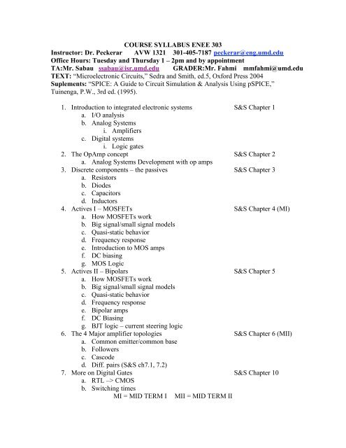
<strong>COURSE</strong> <strong>SYLLABUS</strong> <strong>ENEE</strong> <strong>303</strong><br />
<strong>Instructor</strong>: <strong>Dr</strong>. <strong>Peckerar</strong> <strong>AVW</strong> 1321 301-405-7187 peckerar@eng.umd.edu<br />
Office Hours: Tuesday and Thursday 1 – 2pm and by appointment<br />
TA:Mr. Sabau ssabau@isr.umd.edu GRADER:Mr. Fahmi mmfahmi@umd.edu<br />
TEXT: “Microelectronic Circuits,” Sedra and Smith, ed.5, Oxford Press 2004<br />
Suplements: “SPICE: A Guide to Circuit Simulation & Analysis Using pSPICE,”<br />
Tuinenga, P.W., 3rd ed. (1995).<br />
1. Introduction to integrated electronic systems S&S Chapter 1<br />
a. I/O analysis<br />
b. Analog Systems<br />
i. Amplifiers<br />
c. Digital systems<br />
i. Logic gates<br />
2. The OpAmp concept S&S Chapter 2<br />
a. Analog Systems Development with op amps<br />
3. Discrete components – the passives S&S Chapter 3<br />
a. Resistors<br />
b. Diodes<br />
c. Capacitors<br />
d. Inductors<br />
4. Actives I – MOSFETs S&S Chapter 4 (MI)<br />
a. How MOSFETs work<br />
b. Big signal/small signal models<br />
c. Quasi-static behavior<br />
d. Frequency response<br />
e. Introduction to MOS amps<br />
f. DC biasing<br />
g. MOS Logic<br />
5. Actives II – Bipolars S&S Chapter 5<br />
a. How MOSFETs work<br />
b. Big signal/small signal models<br />
c. Quasi-static behavior<br />
d. Frequency response<br />
e. Bipolar amps<br />
f. DC Biasing<br />
g. BJT logic – current steering logic<br />
6. The 4 Major amplifier topologies S&S Chapter 6 (MII)<br />
a. Common emitter/common base<br />
b. Followers<br />
c. Cascode<br />
d. Diff. pairs (S&S ch7.1, 7.2)<br />
7. More on Digital Gates S&S Chapter 10<br />
a. RTL –> CMOS<br />
b. Switching times<br />
MI = MID TERM I MII = MID TERM II