Purpose RiSC-16 Instruction Set Project 1: Assembler ... - ECE
Purpose RiSC-16 Instruction Set Project 1: Assembler ... - ECE
Purpose RiSC-16 Instruction Set Project 1: Assembler ... - ECE

Create successful ePaper yourself
Turn your PDF publications into a flip-book with our unique Google optimized e-Paper software.
ENEE 646: Digital Computer Design — <strong>Project</strong> 1 (10%)<br />
<br />
<br />
<strong>Project</strong> 1: <strong>Assembler</strong> & Simple Verilog CPU (10%)<br />
ENEE 646: Digital Computer Design, Fall 2011<br />
Assigned: Wednesday, Aug 31; Due: Wednesday, Sep 14<br />
<br />
<br />
<strong>Purpose</strong><br />
<br />
This assignment has two primary goals: to teach you the rudiments of the Verilog hardware description<br />
<br />
language and to show you how software assembles programs into machine-level code. The project has<br />
<br />
two parts. For the first part, you will write a C-language program that reads in an assembly-language<br />
program and produces the corresponding machine code. For the second part, you will write a Verilog-<br />
<br />
language behavioral simulator for arbitrary machine code. In writing an assembler, you will learn about<br />
<br />
file I/O and how CPUs interpret numbers as instructions. When writing your Verilog program, you<br />
<br />
will learn about non-blocking assignments and concurrency. Non-blocking assignments are specific to<br />
<br />
the Verilog language; concurrency is a powerful concept that shows up at all levels of processor design.<br />
<br />
The processor model will be a simple sequential implementation—on every cycle, you will execute an<br />
instruction and update the program counter accordingly.<br />
<br />
<strong>RiSC</strong>-<strong>16</strong> <strong>Instruction</strong> <strong>Set</strong><br />
<br />
Before we talk about the C-language assembler and Verilog-language CPU implementations, we have to<br />
<br />
talk about the instruction-set architecture (ISA) that you are working with. This section describes the<br />
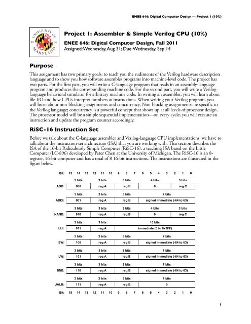
ISA of the <strong>16</strong>-bit Ridiculously Simple Computer (<strong>RiSC</strong>-<strong>16</strong>), <br />
a teaching ISA based on the Little<br />
<br />
Computer (LC-896) developed by Peter Chen at the University of Michigan. The <strong>RiSC</strong>-<strong>16</strong> is an 8register,<br />
<strong>16</strong>-bit computer and has a total of 8 <strong>16</strong>-bit instructions. The instructions are illustrated in the<br />
<br />
figure below.<br />
<br />
<br />
<br />
<br />
<br />
<br />
<br />
<br />
<br />
<br />
<br />
<br />
<br />
<br />
<br />
<br />
<br />
<br />
<br />
<br />
<br />
<br />
<br />
<br />
<br />
<br />
<br />
<br />
<br />
<br />
<br />
<br />
<br />
<br />
<br />
<br />
<br />
<br />
<br />
<br />
<br />
<br />
<br />
<br />
<br />
<br />
<br />
<br />
<br />
<br />
<br />
<br />
<br />
1
There are 3 machine-code instruction formats: RRR-type, RRI-type, and RI-type.<br />
All addresses <br />
are shortword-addresses (i.e. address 0 corresponds to the first two bytes of main memory,<br />
address 1 corresponds to the second two bytes of main memory, etc.). Like the MIPS instruction-set<br />
architecture, <br />
by hardware convention, register 0 will always contain the value 0. The machine enforces<br />
this: reads <br />
to register 0 always return 0, irrespective of what has been written there. The <strong>RiSC</strong>-<strong>16</strong> is very<br />
simple, but <br />
it is general enough to solve complex problems. The following table describes the different<br />
<br />
instruction operations.<br />
Mnemonic<br />
<br />
<br />
<br />
Opcode Assembly<br />
Name and Format<br />
(binary) Format<br />
<br />
<br />
<br />
<br />
<br />
Action<br />
<br />
<br />
add<br />
Add<br />
RRR-type 000<br />
<br />
<br />
add rA, rB, rC<br />
<br />
Add contents of regB with regC,<br />
store result <br />
in regA.<br />
<br />
addi<br />
nand<br />
lui<br />
sw<br />
lw<br />
bne<br />
jalr<br />
001 addi rA, rB, imm<br />
<br />
Nand<br />
RRR-type<br />
<br />
<br />
<br />
010<br />
<br />
<br />
<br />
<br />
<br />
nand rA, rB, rC<br />
<br />
Load Upper Immediate<br />
<br />
RI-type<br />
<br />
011<br />
<br />
lui rA, imm<br />
<br />
Store Word<br />
<br />
RRI-type<br />
Load Word<br />
<br />
RRI-type<br />
Add contents <br />
of regB with imm,<br />
<br />
store result in regA.<br />
<br />
Nand <br />
contents of regB with regC,<br />
store results in regA.<br />
<br />
<br />
Place the top 10 bits of the <strong>16</strong>-bit imm into the top 10 bits of regA,<br />
<br />
setting the bottom 6 bits of regA to zero.<br />
<br />
Store value <br />
<br />
from regA into memory. Memory address is formed by adding<br />
100 sw rA, rB, imm<br />
<br />
<br />
imm with contents of regB.<br />
101 lw rA, rB, imm<br />
<br />
Load value <br />
from memory into regA. Memory address is formed by adding<br />
<br />
imm with contents of regB.<br />
<br />
Branch if Not Equal<br />
If the contents of regA and regB are not the same, branch to the address<br />
<br />
110 bne rA, rB, imm<br />
RRI-type<br />
PC+1+imm, where PC is the address of the bne instruction.<br />
Jump And Link Register<br />
RRI-type<br />
ENEE 646: Digital Computer Design — <strong>Project</strong> 1 (10%)<br />
<br />
<br />
<br />
<br />
Add Immediate <br />
<br />
<br />
RRI-type<br />
<br />
<br />
<br />
<br />
<br />
<br />
<br />
<br />
<br />
<br />
<br />
<br />
<br />
Branch to the address in regB.<br />
111 jalr rA, rB<br />
<br />
<br />
<br />
Store PC+1 into regA, where PC is the address of the jalr instruction.<br />
Note that the 8 <br />
basic instructions of the <strong>RiSC</strong>-<strong>16</strong> architecture form a complete ISA that can perform<br />
arbitrary computation. For example:<br />
<br />
<br />
<br />
<br />
<br />
<br />
<br />
• Moving <br />
constant values into registers. The number 0 can be moved into any register in one<br />
cycle (add <br />
rX r0 r0). Any number between -64 and 63 can be placed into a register in one<br />
operation using the ADDI instruction (addi rX r0 number). Moreover, any <strong>16</strong>-bit number<br />
<br />
can be moved into a register in two operations (lui+addi).<br />
• Subtracting numbers. Subtracting is simply adding the negative value. Any number can be<br />
made negative in two instructions by flipping its bits and adding 1. Bit-flipping can be done by<br />
NANDing the value with itself; adding 1 is done with the ADDI instruction. Therefore,<br />
subtraction is a three-instruction process. Note that without an extra register, it is a destructive<br />
process.<br />
• Multiplying numbers. Multiplication is easily done by repeated addition, bit-testing, and leftshifting<br />
a bitmask by one bit (which is the same as an addition with itself).<br />
<br />
<br />
<br />
2
<strong>RiSC</strong> Assembly Language and <strong>Assembler</strong><br />
The first half of this project is to write a program to take an assembly-language program and translate it<br />
into machine-level code. You will translate assembly language names for instructions, such as bne, into<br />
their numeric equivalent (e.g. 110), and you will translate symbolic names for addresses into numeric<br />
values. The final output produced by the assembler will be a series of <strong>16</strong>-bit instructions, written as<br />
ASCII text, hexadecimal format, one line per instruction (i.e. each number separated by newlines).<br />
The format for a line of assembly code is:<br />
label:opcodefield0, field1, field2# comments<br />
The leftmost field on a line is the label field. Valid <strong>RiSC</strong> labels are any combination of letters and<br />
numbers followed by a colon. Labels make it much easier to write assembly language programs, since<br />
otherwise you would need to modify all address fields each time you added a line to your assemblylanguage<br />
program! The colon at the end of the label is not optional—a label without a colon is<br />
interpreted as an opcode. After the optional label is whitespace (space/s or tab/s). Then follows the<br />
opcode field, where the opcode can be any of the assembly-language instruction mnemonics listed in<br />
the above table. After more whitespace comes a series of fields separated by commas and possibly<br />
whitespace (the whitespace is not necessary; the commas are). For the purposes of this assignment, all<br />
fields are to be given as decimal numbers (this way, you do not have to deal with hexadecimal formats,<br />
etc.). The number of fields depends on the instruction. Some instructions will have three fields; others<br />
two fields; while some will have no fields beyond the opcode. Anything after a pound sign (‘#’) is<br />
considered a comment and is ignored. The comment field ends at the end of the line. Comments are<br />
vital to creating understandable assembly-language programs, because the instructions themselves are<br />
rather cryptic. The following table describes the behavior of the instructions in C-like syntax.<br />
Assembly-Code Format Meaning<br />
add regA, regB, regC R[regA]
The following paragraphs describe these pseudo-instructions in more detail:<br />
• The nop pseudo-instruction means “do not do anything this cycle” and is replaced by the<br />
instruction add 0,0,0 (which clearly does nothing).<br />
• The halt pseudo-instruction means “stop executing instructions & print current machine state”<br />
and is replaced by jalr 0, 0 with a non-zero immediate having the value 113 decimal (chosen<br />
for historical reasons). Therefore the halt instruction is the hexadecimal number 0xE071.<br />
• The .fill directive tells the assembler to put a number into the place where the instruction<br />
would normally be stored. The .fill directive uses one field, which can be either a numeric value<br />
(in decimal, hexadecimal, or octal) or a symbolic address (i.e. a label). For example, “.fill 32”<br />
puts the value 32 where the instruction would normally be stored; “.fill 0x10” also puts the<br />
value 32 (decimal) where the instruction would normally be stored in the assembler provided).<br />
Using .fill with a symbolic address will store the address of the label. In the example below, the<br />
line “.fill start” will store the value 2, because the label “start” refers to address 2.<br />
When labels are used as part of instructions (e.g. the immediate values for lw, sw, .fill, lui, bne, and<br />
even addi instructions), they refer to the value of the label (the address at which the label occurs), and<br />
they are interpreted slightly differently depending on the instruction in which they are found:<br />
• For lw, sw, lui, or .fill instructions, the assembler should compute the immediate value to be<br />
equal to the address of the label. Therefore if a label appears in an immediate field, it should be<br />
interpreted as the address at which the label is found. In the case of lw or sw, this could be used<br />
with a zero base register to refer to the label, or could be used with a non-zero base register to<br />
index into an array starting at the label.<br />
• Labels are slightly different for bne instructions: the assembler should not use the label’s address<br />
directly but instead should determine the numeric immediate value needed to branch to that<br />
label. The bne description shows the program counter being updated by the immediate value<br />
(PC
Be sure you understand how the above assembly-language program got translated to this machine-code<br />
file.<br />
Running Your <strong>Assembler</strong><br />
You must write your program so that it is run as follows (assuming your program name is “assemble”).<br />
assemble assembly-code-file machine-code-file<br />
Note that the format for running the command must use command-line arguments for the file names<br />
(rather than standard input and standard output). The first argument is the file name where the<br />
assembly-language program is stored, and the second argument is the file name where the output (the<br />
machine-code) is written. Your program should only store the list of hexadecimal numbers in the<br />
machine-code file, one instruction per line—any other format will render your machine-code file<br />
ungradable. Each number can have ‘0x’ in front or not, as you wish. Any other output that you want<br />
the program to generate (e.g. debugging output) can be printed to stdout or stderr.<br />
Error Checking<br />
Your assembler should catch errors in the assembly language program, as well as errors that occur<br />
because the user ran your program incorrectly (e.g. with only 1 argument instead of 2 arguments). For<br />
example, it should detect the use of undefined labels, duplicate labels, missing arguments to opcodes<br />
(e.g. only giving two fields to lw), immediate values that are out of range, unrecognized opcodes, etc.<br />
Code Fragment for <strong>Assembler</strong><br />
The focus of this class is machine organization, not C programming skills. To help you, here is a<br />
fragment of the C program for the assembler. This shows how to specify command-line arguments to<br />
the program (via argc and argv), how to parse the assembly-language file, etc. This fragment is<br />
provided strictly to help you, though it may take a bit for you to understand and use the file. You may<br />
also choose to not use this fragment.<br />
/* <strong>Assembler</strong> code fragment for <strong>RiSC</strong> */<br />
#include <br />
#include <br />
#define MAXLINELENGTH 1000<br />
char * readAndParse(FILE *inFilePtr, char *lineString,<br />
char **labelPtr, char **opcodePtr, char **arg0Ptr,<br />
char **arg1Ptr, char **arg2Ptr)<br />
{<br />
/* read and parse a line<br />
note that lineString must point to allocated memory, so that *labelPtr,<br />
*opcodePtr, and *argXPtr won’t be pointing to readAndParse’s memory<br />
note also that *labelPtr, *opcodePtr, and *argXPtr<br />
point to memory locations in lineString.<br />
When lineString changes, so will *labelPtr, *opcodePtr, and *argXPtr.<br />
function returns NULL if at end-of-file */<br />
char *statusString, *firsttoken;<br />
statusString = fgets(lineString, MAXLINELENGTH, inFilePtr);<br />
ENEE 646: Digital Computer Design — <strong>Project</strong> 1 (10%)<br />
if (statusString != NULL) {<br />
firsttoken = strtok(lineString, " \t\n");<br />
if (firsttoken == NULL || firsttoken[0] == ’#’) {<br />
return readAndParse(inFilePtr, lineString, labelPtr,<br />
opcodePtr, arg0Ptr, arg1Ptr, arg2Ptr);<br />
} else if (firsttoken[strlen(firsttoken) - 1] == ’:’) {<br />
*labelPtr = firsttoken;<br />
*opcodePtr = strtok(NULL, " \n");<br />
firsttoken[strlen(firsttoken) - 1] = ’\0’;<br />
} else {<br />
*labelPtr = NULL;<br />
*opcodePtr = firsttoken;<br />
}<br />
5
}<br />
*arg0Ptr = strtok(NULL, ", \t\n");<br />
*arg1Ptr = strtok(NULL, ", \t\n");<br />
*arg2Ptr = strtok(NULL, ", \t\n");<br />
}<br />
return(statusString);<br />
int isNumber(char *string) {<br />
/* return 1 if string is a number */<br />
int i;<br />
return( (sscanf(string, “%d”, &i)) == 1);<br />
}<br />
main(int argc, char *argv[])<br />
{<br />
char *inFileString, *outFileString;<br />
FILE *inFilePtr, *outFilePtr;<br />
char *label, *opcode, *arg0, *arg1, *arg2;<br />
char lineString[MAXLINELENGTH+1];<br />
}<br />
C Programming Tips<br />
if (argc != 3) {<br />
printf(“error: usage: %s <br />
\n”, argv[0]);<br />
exit(1);<br />
}<br />
inFileString = argv[1];<br />
outFileString = argv[2];<br />
inFilePtr = fopen(inFileString, “r”);<br />
if (inFilePtr == NULL) {<br />
printf(“error in opening %s\n”, inFileString);<br />
exit(1);<br />
}<br />
outFilePtr = fopen(outFileString, “w”);<br />
if (outFilePtr == NULL) {<br />
printf(“error in opening %s\n”, outFileString);<br />
exit(1);<br />
}<br />
ENEE 646: Digital Computer Design — <strong>Project</strong> 1 (10%)<br />
/* here is an example for how to use readAndParse to read a line from inFilePtr */<br />
if (readAndParse(inFilePtr, lineString, &label, &opcode,<br />
&arg0, &arg1, &arg2) == NULL) {<br />
/* reached end of file */<br />
} else {<br />
/* label is either NULL or it points to<br />
a null-terminated string in lineString<br />
that has the label. If label is NULL,<br />
that means the label field didn’t exist.<br />
Same for opcode and argX. */<br />
}<br />
/* this is how to rewind file ptr to start reading from beginning of file */<br />
rewind(inFilePtr);<br />
/* after a readAndParse, you may want to do the following to test each opcode */<br />
if (!strcmp(opcode, “add”)) {<br />
/* do whatever you need to do for opcode “add” */<br />
}<br />
Here are a few programming tips for writing C programs to manipulate bits and then print them out:<br />
1. To indicate a hexadecimal constant in C, precede the number by 0x. For example, 27 decimal is<br />
0x1b in hexadecimal.<br />
2. The value of the expression (a >> b) is the number a shifted right by b bits. Neither a nor b are<br />
changed. E.g. (25 >> 2) is 6. Note that 25 is 11001 in binary, and 6 is 110 in binary.<br />
3. The value of the expression (a
5. The value of the expression (a & b) is a logical AND on each bit of a and b (i.e. bit 15 of a<br />
ANDed with bit 15 of b, bit 14 of a ANDed with bit 14 of b, etc.). E.g. (25 & 11) is 9, since:<br />
11001 (binary)<br />
& 01011 (binary)<br />
-----------------<br />
= 01001 (binary),<br />
which is 9 decimal.<br />
6. The value of the expression (a | b) is a logical OR on each bit of a and b (i.e. bit 15 of a ORed<br />
with bit 15 of b, bit 14 of a ORed with bit 14 of b, etc.). E.g. (25 | 11) is 27, since:<br />
11001 (binary)<br />
| 01011 (binary)<br />
-----------------<br />
= 11011 (binary),<br />
which is 27 decimal.<br />
Use these operations to create and manipulate machine-code. E.g. to look at bit 3 of the variable a, you<br />
might do: (a>>3) & 0x1. To look at bits 15-13 of a <strong>16</strong>-bit word (for instance, the opcode of each<br />
instruction), you could do: (a>>13) & 0x7. To put a 6 into bits 5-3 and a 3 into bits 2-1, you could do<br />
the following: (6
the skeleton code shown below. You should be able to develop your processor model well within a<br />
week.<br />
Clearly, the main point of this exercise is not to investigate advanced architecture concepts but to teach<br />
you the rudiments of the Verilog modeling language. Future projects will explore more advanced<br />
architecture concepts like pipelines and precise interrupts.<br />
You have been given a skeleton Verilog file that looks like this:<br />
//<br />
// <strong>RiSC</strong>-<strong>16</strong> skeleton<br />
//<br />
`define ADD 3’d0<br />
`define ADDI 3’d1<br />
`define NAND 3’d2<br />
`define LUI 3’d3<br />
`define SW 3’d4<br />
`define LW 3’d5<br />
`define BNE 3’d6<br />
`define JALR 3’d7<br />
`define EXTEND 3’d7<br />
`define INSTRUCTION_OP 15:13 // opcode<br />
`define INSTRUCTION_RA 12:10 // rA<br />
`define INSTRUCTION_RB 9:7 // rB<br />
`define INSTRUCTION_RC 2:0 // rC<br />
`define INSTRUCTION_IM 6:0 // immediate (7-bit, to be sign-extended)<br />
`define INSTRUCTION_LI 9:0 // large immediate (10-bit, to be 0-extended)<br />
`define INSTRUCTION_SB 6 // immediate’s sign bit<br />
`define ZERO <strong>16</strong>’d0<br />
`define HALTINSTRUCTION { `EXTEND, 3’d0, 3’d0, 3’d7, 4’d1 }<br />
module <strong>RiSC</strong> (clk);<br />
input clk;<br />
reg [15:0] rf[0:7];<br />
reg [15:0] pc;<br />
reg [15:0] m[0:65535];<br />
endmodule<br />
always @(negedge clk) begin<br />
rf[0]
Finally, the input to the <strong>RiSC</strong> module is the clock signal, which indicates that the module is not freestanding—it<br />
must be instantiated elsewhere to run. That is the function of test modules. You have also<br />
been given a file called “test.v” which instantiates the <strong>RiSC</strong> … it looks like this:<br />
module top ();<br />
reg clk;<br />
<strong>RiSC</strong> cpu(clk);<br />
integer j;<br />
initial begin<br />
pc = 0;<br />
rf[0] = `ZERO;<br />
rf[1] = `ZERO;<br />
rf[2] = `ZERO;<br />
rf[3] = `ZERO;<br />
rf[4] = `ZERO;<br />
rf[5] = `ZERO;<br />
rf[6] = `ZERO;<br />
rf[7] = `ZERO;<br />
for (j=0; j