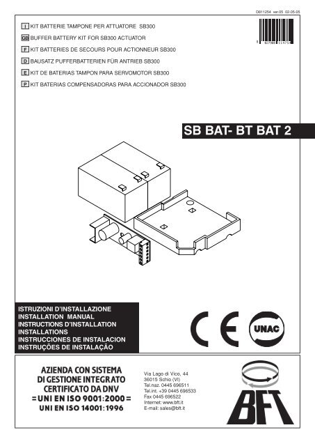
SB BAT- BT BAT 2
SB BAT- BT BAT 2
SB BAT- BT BAT 2
Create successful ePaper yourself
Turn your PDF publications into a flip-book with our unique Google optimized e-Paper software.
I<br />
GB BUFFER <strong>BAT</strong>TERY KIT FOR <strong>SB</strong>300 ACTUATOR<br />
F<br />
D<br />
E<br />
P<br />
KIT <strong>BAT</strong>TERIE TAMPONE PER ATTUATORE <strong>SB</strong>300<br />
KIT <strong>BAT</strong>TERIES DE SECOURS POUR ACTIONNEUR <strong>SB</strong>300<br />
BAUSATZ PUFFER<strong>BAT</strong>TERIEN FÜR ANTRIEB <strong>SB</strong>300<br />
KIT DE <strong>BAT</strong>ERIAS TAMPON PARA SERVOMOTOR <strong>SB</strong>300<br />
KIT <strong>BAT</strong>ERIAS COMPENSADORAS PARA ACCIONADOR <strong>SB</strong>300<br />
ISTRUZIONI D’INSTALLAZIONE<br />
INSTALLATION MANUAL<br />
INSTRUCTIONS D’INSTALLATION<br />
INSTALLATIONS<br />
INSTRUCCIONES DE INSTALACION<br />
INSTRUÇÕES DE INSTALAÇÃO<br />
Via Lago di Vico, 44<br />
36015 Schio (VI)<br />
Tel.naz. 0445 696511<br />
Tel.int. +39 0445 696533<br />
Fax 0445 696522<br />
Internet: www.bft.it<br />
E-mail: sales@bft.it<br />
D811254 ver.05 02-05-05<br />
<br />
<strong>SB</strong> <strong>BAT</strong>- <strong>BT</strong> <strong>BAT</strong> 2
ITALIANO MANUALE D’INSTALLAZIONE<br />
INSTALLATION MANUAL ENGLISH<br />
1) GENERALITÀ<br />
Kit batteria tampone mod. <strong>SB</strong> <strong>BAT</strong>.<br />
Incorporabile nell’attuatore mod. <strong>SB</strong>300, consente il funzionamento del-l’automazione<br />
anche se manca per un breve periodo l’alimentazione di rete.<br />
La confezione é composta da (fig.1):<br />
• 2 batterie a tampone (rif.B).<br />
• 1 base porta batterie (rif.BB).<br />
• 1 scheda carica batterie (rif.<strong>SB</strong>S).<br />
• Manuale istruzioni per il montaggio.<br />
• Confezione viteria e cablaggi vari (rif.D-R-V).<br />
2) CARATTERISTICHE SCHEDA <strong>SB</strong>S E <strong>BAT</strong>TERIE<br />
Tensione di carica: ..........................................................................................27.2Vdc<br />
Corrente di carica: ............................................................................................130mA<br />
Dati rilevati alla temperatura esterna di: .............................................................. 25°C<br />
Capacità batteria: ................................................................................ 2x (12V 1.2Ah)<br />
Soglia protezione batteria scarica: .................................................................20.4Vdc<br />
Tempo di ricarica batteria: ............................................................................... 12/14 h<br />
3) MONTAGGIO<br />
Tutte le operazioni di montaggio e collegamento devono essere effettuate da personale<br />
qualificato. Per applicare l’accessorio procedere come segue:<br />
<strong>SB</strong> <strong>BAT</strong><br />
- Togliere l’alimentazione di rete.<br />
- Togliere i coperchi dell’attuatore e della scatola della centralina.<br />
- Rompere il diaframma e applicare il passacavo “C”.<br />
- Fissare la schedina carica batterie nello spazio indicato (fig.1- rif. <strong>SB</strong>S).<br />
- Fissare la base batterie sul trasformatore nel modo e verso indicato (fig.1- rif.<br />
BB-D-R-V).<br />
- Appoggiare le due batterie (fig.1- rif.B) sulla base.<br />
<strong>BT</strong> <strong>BAT</strong> 2<br />
- Togliere l’alimentazione di rete.<br />
- Togliere i coperchi dell’attuatore e della scatola della centralina.<br />
- Rompere il diaframma e applicare il passacavo “C”.<br />
- Fissare la schedina carica batterie nello spazio indicato (fig.1- rif. <strong>SB</strong>S).<br />
- Svitare le viti del trasformatore “V1”, posizionare la staffa “S” sul trasformatore e<br />
fissare il tutto con le viti “V1” all’attuatore.<br />
- Fissare la base batterie “BB” sulla staffa “S” nel modo e verso indicato (fig.1 D-<br />
R-V).<br />
- Appoggiare le due batterie (fig.1-rif.B) sulla base “BB”.<br />
4) COLLEGAMENTI<br />
Per eseguire il collegamento dei cablaggi presenti nel Kit, procedere come segue e<br />
rispettare la numerazione dello schema in fig.2.<br />
- Scollegare il morsetto 4 dalla scheda QSC e sguainarlo dalla guaina esistente.<br />
- Inguainare nella guaina in dotazione, i collegamenti (++) rosso, (- -) nero ed il<br />
collegamento 44 del trasformatore.<br />
- Eseguire i collegamenti come indicato nello schema.<br />
- Collegare in serie le batterie con il cavetto rosso al + / -.<br />
- Riporre i coperchi alla scatola centralina e all’attuatore fissandoli con le apposite<br />
viti.<br />
- Ripristinare l’alimentazione da rete.<br />
5) RIMOZIONE DELLE <strong>BAT</strong>TERIE<br />
P e r l a r i m o z i o n e d e l l e b a t t e r i e a t t e n e r s i a l l e<br />
normative vigenti ed in particolare:<br />
1) Rimuovere le batterie prima dello smantellamento dell’automazione.<br />
2) Le batterie devono essere eliminate in modo sicuro.<br />
3) L’apparecchiatura deve essere scollegata dall’alimentazione durante la rimozione<br />
delle batterie.<br />
Le descrizioni e le illustrazioni del presente manuale non sono impegnative.<br />
Lasciando inalterate le caratteristiche essenziali del prodotto, la Ditta si riserva<br />
di apportare in qualunque momento le modifiche che essa ritiene convenienti<br />
per migliorare tecnicamente, costruttivamente e commercialmente il prodotto,<br />
senza impegnarsi ad aggiornare la presente pubblicazione.<br />
2 - <strong>SB</strong> <strong>BAT</strong>-<strong>BT</strong> <strong>BAT</strong> 2 - Ver. 05<br />
1) GENERAL OUTLINE<br />
<strong>SB</strong> <strong>BAT</strong> mod. buffer battery kit.<br />
It can be incorporated into the <strong>SB</strong>300 actuator and allows the automation<br />
system to operate even when the mains power supply is disconnected for<br />
a short time. The pack includes (fig.1):<br />
• 2 buffer batteries (ref. B).<br />
• 1 battery holder base (ref. BB).<br />
• 1 battery charger board (ref. <strong>SB</strong>S).<br />
• Assembly instruction manual.<br />
• Various bolts, screws and cables (rif.D-R-V).<br />
2) <strong>SB</strong>S BOARD AND <strong>BAT</strong>TERY SPECIFICATIONS<br />
Charge voltage: .............................................................................................. 27.2Vdc<br />
Charge current: .................................................................................................130mA<br />
Data detected with external temperature of: ........................................................ 25°C<br />
Battery capacity: .................................................................................. 2x (12V 1.2Ah)<br />
Exhausted battery protection threshold: ......................................................... 20.4Vdc<br />
Battery recharging time: .................................................................................. 12/14 h<br />
3) FITTING<br />
All assembly and connection operations must be carried out by qualified personnel. To<br />
fit the accessory, proceed as follows:<br />
<strong>SB</strong> <strong>BAT</strong><br />
- Disconnect the mains power supply.<br />
- Remove the covers from the actuator and the control unit box.<br />
- Break the diaphragm and fit cable holder “C”.<br />
- Secure thebatterychargerboard inthespaceindicated (fig.1-ref.<strong>SB</strong>S).<br />
- Secure the battery base on the transformer in the way and direction<br />
indicated (fig.1- ref. BB-D-R-V).<br />
- Place the two batteries (fig.1- ref. B) onto the base.<br />
<strong>BT</strong> <strong>BAT</strong> 2<br />
- Disconnect the mains power supply.<br />
- Remove the covers from the actuator and the control unit box.<br />
- Break the diaphragm and fit cable holder “C”.<br />
- Secure thebatterychargerboard inthespaceindicated (fig.1-ref.<strong>SB</strong>S).<br />
- Loosen the screws on the “V1” transformer, place the “S” bracket on the transformer<br />
and fix everything onto the operator by means of the “V1” screws.<br />
- Fasten the “BB” battery base onto the “S” bracket observing the way and direction<br />
indicated (fig.1 D-R-V).<br />
- Place the two batteries (fig.1-rif.B) onto the “BB” base.<br />
4) CONNECTIONS<br />
To connect the cables supplied with the Kit, proceed as follows and respect<br />
the number sequence used in the diagram in fig.2.<br />
- Disconnect terminal 4 from the QSC board and take it out of the existing sheath.<br />
- Insert the red (++) and black (- -) connections, as well as the transformer connection,<br />
in the sheath supplied.<br />
- Proceed to connect the cables as shown in the diagram.<br />
- Connect the batteries in series with the red cable at + / -.<br />
- Replace the covers on the control unit box and actuator, and secure<br />
them using the appropriate screws.<br />
- Restore the mains power supply.<br />
5) <strong>BAT</strong>TERY REMOVAL<br />
W h e n r e m o v i n g t h e b a t t e r i e s , o b s e r v e t h e<br />
current regulations and in particular:<br />
1) Remove the batteries before dismantling the operator.<br />
2) The batteries must be discarded safely.<br />
3) The appliance must be disconnected from the power supply during battery<br />
removal.<br />
The descriptions and illustrations contained in the present manual are not<br />
binding.<br />
The Company reserves the right to make any alterations deemed appropriate<br />
for the technical, manufacturing and commercial improvement of the product,<br />
whileleaving the essential product features unchanged, at any time and without<br />
undertaking to update the present publication.<br />
D811254_05
D811254_05<br />
FRANÇAIS MANUEL D’INSTALLATION<br />
MONTAGEANLEITUNG DEUTSCH<br />
1) GENERALITES<br />
Kit batterie de secours mod. <strong>SB</strong> <strong>BAT</strong>.<br />
Elle peut être incorporée dans l’actionneur mod. <strong>SB</strong>300 et permet le fonctionnement<br />
de la motorisation même en cas de faute d’électricité pour<br />
une courte période. L’emballage comprend (fig.1):<br />
• 2 batteries de secours (réf. B).<br />
• 1 base porte-batteries (réf. BB).<br />
• 1 carte de chargement des batteries (réf. <strong>SB</strong>S).<br />
• Manuel d’instructions pour le montage.<br />
• Boîte visserie et câblages divers (rif.D-R-V).<br />
2) CARACTERISTIQUES DE LA CARTE <strong>SB</strong>S ET DES <strong>BAT</strong>TERIES<br />
Tension de chargement: ................................................................................. 27.2Vdc<br />
Courant de chargement: ...................................................................................130mA<br />
Données mesurée à la température extérieure de: ............................................. 25°C<br />
Capacité de la batteria: ........................................................................ 2x (12V 1.2Ah)<br />
Seuil de protection de batterie à plat: ............................................................. 20.4Vdc<br />
Temps de rechargement batterie: .................................................................... 12/14 h<br />
3) MONTAGE<br />
Toutes les opérations de montage et de connexion doivent être effectuées par du personnel<br />
qualifié. Pour appliquer l’accessoire, procéder comme suit.<br />
<strong>SB</strong> <strong>BAT</strong><br />
- Couper l’alimentation de ligne.<br />
- Enlever lescouverclesdel’actionneur et delaboîte del’unitédecommande.<br />
- Casser le diaphragme et appliquer le passe-câble “C”.<br />
- Fixer la carte de chargement des batteries dans l’espace indiqué (fig. 1 - réf.<br />
<strong>SB</strong>S).<br />
- Fixer la base des batteries sur le transformateur comme indiqué à la fig.1 -réf.<br />
BB-D-R-V.<br />
- Poser les deux batteries (fig.1- réf. B) sur la base.<br />
<strong>BT</strong> <strong>BAT</strong> 2<br />
- Couper l’alimentation de ligne.<br />
- Enlever lescouverclesdel’actionneur et delaboîte del’unitédecommande.<br />
- Casser le diaphragme et appliquer le passe-câble “C”.<br />
- Fixer la carte de chargement des batteries dans l’espace indiqué (fig. 1 - réf. <strong>SB</strong>S).<br />
- Dévisser les vis du transformateur “V1”; positionner la patte “S” sur le transformateur<br />
et fixer le tout à l’actionneur au moyen des vis “V1”.<br />
- Fixer la base des batteries “BB” à la patte “S” de la façon et dans la direction indiquées<br />
(Fig. 1 D-R-V).<br />
- Poser les deux batteries (Fig. 1 – réf. B) sur la base “BB”<br />
4) CONNEXIONS<br />
Pour effectuer la connexion des câblages présents dans le Kit, procéder<br />
comme suit et respecter le numérotage du schéma de la fig.2.<br />
- Débrancher la borne 4 de la carte QSC et la retirer de la gaine existante.<br />
- Passer les connexions, (++) rouge, (- -) noir et la connexion 44<br />
du transformateur dans la gaine fournie en dotation.<br />
- Effectuer les connexions comme indiqué dans le schéma.<br />
- Connecter en série les batteries avec le câble rouge au + / -.<br />
- Remettre en place les couvercles de l’unité de commande et de<br />
l’actionneur en les fixant avec les vis spéciales.<br />
- Appliquer l’alimentation de ligne.<br />
5) ENLÈVEMENT DES <strong>BAT</strong>TERIES<br />
P o u r l ’ e n l è v e m e n t d e s b a t t e r i e s , s u i v r e l e s<br />
normes en vigueur et notamment:<br />
1) Enlever les batteries avant le démantèlement de l’automatisme.<br />
2) Les batteries doivent être mises au rebut d’une façon sûre.<br />
3) L’appareillage doit être déconnecté de l’alimentation pendant l’enlèvement des<br />
batteries.<br />
Les descriptions et les figures de ce manuel n’engagent pas le constructeur.<br />
En laissant inaltérées les caractéristiques essentielles du produit, la Société se<br />
réserve le droit d’apporter à n’importe quel moment les modifications qu’elle juge<br />
opportunes pour améliorer le produit du point de vue technique, commercial et<br />
de construction, sans s’engager à mettre à jour cette publication.<br />
1) ALLGEMEINES<br />
Satz Pufferbatterien Modell <strong>SB</strong> <strong>BAT</strong>.<br />
Einbaufähig in den Antrieb Modell <strong>SB</strong>300 erlaubt er den Betrieb der Automatikanlage<br />
auch bei kurzzeitigem Stromausfall. Die Verpackung besteht aus (Abb.1):<br />
• 2 Pufferbatterien (B).<br />
• 1 Batteriebasis (BB).<br />
• 1 Batterieaufladekarte (rif. <strong>SB</strong>S).<br />
• Montageanleitung.<br />
• Packung verschiedene Schrauben und Kabel (rif.D-R-V).<br />
2) EIGENSCHAFTEN KARTE <strong>SB</strong>S UND <strong>BAT</strong>TERIEN<br />
Ladespannung: ............................................................................................... 27.2Vdc<br />
Ladestrom: ........................................................................................................130mA<br />
Werte gemessen bei Außentemperatur von: ....................................................... 25°C<br />
Batterieleistung: ................................................................................... 2x (12V 1.2Ah)<br />
Sicherungsschwelle Batterieentleerung: ........................................................ 20.4Vdc<br />
Nachladezeit der Batterie: ............................................................................... 12/14 h<br />
3) MONTAGE<br />
Alle Montage und Anschlußtätigkeiten müssen von Fachpersonal vorgenommen werden.<br />
Zum Einbau des Zubehörteils wie folgt vorgehen.<br />
<strong>SB</strong> <strong>BAT</strong><br />
- Netzversorgung unterbrechen.<br />
- Die Abdeckungen des Antriebs und des Zentralkastens abnehmen.<br />
- Die Scheidewand aufbrechen und die Kabelstopfbuchse “C” einsetzen.<br />
- Die Batterieaufladekarte am vorgegebenen Ort befestigen (Abb.1 - <strong>SB</strong>S).<br />
- Die Batteriebasis auf die beschriebene. Art und in de vorgeschriebenen. Richtung<br />
auf dem Trafo befestigen (Abb.1- BB-D-R-V).<br />
- Die beiden Batterien (Abb.1- B) auf die Basis legen.<br />
<strong>BT</strong> <strong>BAT</strong> 2<br />
- Netzversorgung unterbrechen.<br />
- Die Abdeckungen des Antriebs und des Zentralkastens abnehmen.<br />
- Die Scheidewand aufbrechen und die Kabelstopfbuchse “C” einsetzen.<br />
- Die Batterieaufladekarte am vorgegebenen Ort befestigen (Abb.1 - <strong>SB</strong>S).<br />
- Die Schrauben des Transformators “V1” abnehmen, den Bügel “S” auf dem<br />
Transformator positionieren und alles zusammen mit den Schrauben “V1” des<br />
Antriebes befestigen.<br />
- Die Batteriebasis “BB” auf dem Bügel “S” in der Art und der Richtung positionieren,<br />
wie es gezeigt wird (Abb.1 D-R-V).<br />
- Die beiden Batterien (Abb. 1- B) auf der Basis “BB” ablegen.<br />
4) ANSCHLÜSSE<br />
Für den Anschluß der im Bausatz enthaltenen Kabel wie folgt vorgehen,<br />
wobei die Numerierung im Schema der Abb.2 zu beachten ist.<br />
- Die Klemme 4 von der Karte QSC lösen und den Mantel entfernen.<br />
- Dieroten (++) undschwarzen (- -) Anschlüsse sowiedenAnschluß44<br />
des Trafos in den beiliegenden Mantel einführen.<br />
- Die Anschlüsse so vornehmen, wie es im Schema gezeigt wird.<br />
- Die Batterien in Serie mit der roten Litze an + / - anschließen.<br />
- Die Abdeckungen wieder auf den Kasten der Zentrale und den Antrieb schrauben.<br />
- Die Netzversorgung wieder herstellen.<br />
5) ENTFERNEN DER <strong>BAT</strong>TERIEN<br />
F ü r d i e E n t f e r n u n g d e r B a t t e r i e n s i n d d i e<br />
geltenden Vorschriften zu beachten, insbesondere folgende:<br />
1) Die Batterien sind vor der Zerlegung der Anlage zu entfernen.<br />
2) Die Batterien müssen sicher entsorgt werden.<br />
3) Das Gerät muß während der Entfernung der Batterien von der Stromversorgung<br />
getrennt werden.<br />
Die Beschreibungen und bildlichen Darstellungen in diesem Hand-buch sind<br />
unverbindlich.<br />
Der Hersteller behält sichohne auch zur Aktualisierung dieser Unterlagen<br />
verpflichtet zu sein - jederzeit vor, Änderungen vornehmen, wenn er diese für<br />
technische und bauliche Produkt-verbesserungen sowie zur Erhöhung der Marktchancen<br />
als notwendig erachtet und die wesentlichen Produkteigenschaften<br />
un-verändert bleiben.<br />
<strong>SB</strong> <strong>BAT</strong>-<strong>BT</strong> <strong>BAT</strong> 2 - Ver. 05 - 3
ESPAÑOL MANUAL DE INSTALACIÓN<br />
MANUAL PARA A INSTALAÇÃO PORTUGUÊS<br />
1) DATOS GENERALES<br />
Kit de baterías tampón mod. <strong>SB</strong> <strong>BAT</strong>.<br />
Incorporable en el servomotor mod. <strong>SB</strong>300, permite el funcionamiento del<br />
automatismo incluso si falta, por un breve período de tiempo, el suministro<br />
de corriente. El lote está compuesto de (fig.1):<br />
• 2 baterías tampón (ref. B).<br />
• 1 base portabaterías (ref. BB).<br />
• 1 tarjeta para cargar las baterías (ref. <strong>SB</strong>S).<br />
• Manual de instrucciones para el montaje.<br />
• Lote de tornillos y cables varios (rif.D-R-V).<br />
2) CARACTERISTICAS DE LA TARJETA <strong>SB</strong>S Y DE LAS <strong>BAT</strong>ERIAS<br />
Tensión de carga: ......................................................................................... 27,2Vc.c.<br />
Corriente de carga: ...........................................................................................130mA<br />
Datos registrados a una temperatura exterior de: .............................................. 25° C<br />
Capacidad batería: .............................................................................. 2x (12V 1,2Ah)<br />
Umbral de protección batería agotada: ........................................................ 20,4Vc.c.<br />
Tiempo de recarga bateria: ............................................................................. 12/14 h<br />
3) MONTAJE<br />
Todos los trabajos de montaje y conexión deben ser hechos por personal experto. Para<br />
aplicar el accesorio, hay que realizar lo siguiente.<br />
<strong>SB</strong> <strong>BAT</strong><br />
- Cortar el suministro de corriente.<br />
- Quitar las tapas del servomotor y de la caja de la central.<br />
- Romper el diafragma y aplicar el pasacables “C”.<br />
- Fijar la tarjeta para cargar las baterías en el espacio indicado (fig.1 -ref.<strong>SB</strong>S).<br />
- Fijar la base de las baterías sobre el transformador de la manera y en<br />
el sentido indicados (fig.1 - ref. BB-D-R-V).<br />
- Apoyar las dos baterías (fig.1 - ref. B) sobre la base.<br />
<strong>BT</strong> <strong>BAT</strong> 2<br />
- Cortar el suministro de corriente.<br />
- Quitar las tapas del servomotor y de la caja de la central.<br />
- Romper el diafragma y aplicar el pasacables “C”.<br />
- Fijar la tarjeta para cargar las baterías en el espacio indicado (fig.1 -ref.<strong>SB</strong>S).<br />
- Destornille los tornillos del transformador “V1”, coloque la abrazadera “S” en el<br />
transformador y fíjelo todo al servomotor con los tornillos “V1”.<br />
- Fije la base de las baterías “BB” en la abrazadera “S” de la manera y en el sentido<br />
indicados (fig. 1 D-R-V).<br />
- Apoye las dos baterías (fig. 1 - ref. B) sobre la base “BB”.<br />
4) CONEXIONES<br />
Para realizar la conexión de los cables presentes en el Kit, hay que realizar<br />
lo siguiente, respetando la numeración del esquema de la fig.2.<br />
- Desconectar el borne 4 de la tarjeta QSC y sacarlo de la vaina existente.<br />
- Introducir, en la vaina asignada, las conexiones (++) rojo, (- -) negro y<br />
la conexión 44 del transformador.<br />
- Realizar las conexiones como se indica en el esquema.<br />
- Conectar en serie las baterías, con el cable rojo, al + / -.<br />
- Montar de nuevo las tapas de la caja de la central y del servomotor,<br />
fijándolas con los tornillos correspondientes.<br />
- Restablecer el suministro de corriente.<br />
5) EXTRACCION DE LAS <strong>BAT</strong>ERIAS<br />
P a r a l a e x t r a c c i ó n d e l a s b a t e r í a s , h a y q u e<br />
seguir las normas vigentes y, en particular:<br />
1) Extraer las baterías antes del desmantelamiento del automatismo.<br />
2) Las baterías deben eliminarse de manera segura.<br />
3) El equipo debe desconectarse de la alimentación antes de empezar la extracción<br />
de las baterías.<br />
Las descripciones y las ilustraciones del presente manual tienen un carácter<br />
puramente indicativo. Dejando inalteradas las características esenciales del producto,<br />
la Empresa se reserva la posibilidad de aportar, en cualquier momento, las<br />
modifi-caciones que considere convenientes para mejorar técnica, constructiva y<br />
comercialmente el producto, sin la obligación de poner al día esta publicación.<br />
4 - <strong>SB</strong> <strong>BAT</strong>-<strong>BT</strong> <strong>BAT</strong> 2 - Ver. 05<br />
1) GENERALIDADES<br />
Kit bateria compensadora mod. <strong>SB</strong> <strong>BAT</strong>.<br />
Pode ser incorporada no accionador mod. <strong>SB</strong>300 e, consente o funciona-mento da<br />
automatização mesmo se falta alimentação de rede por um breve<br />
período. A confecção é composta por (fig.1):<br />
• 2 baterias compensadoras (ref. B).<br />
• 1 base portabaterias (ref. BB).<br />
• 1 placa para carregar as baterias (ref. <strong>SB</strong>S).<br />
• Manual de instruções para a montagem.<br />
• Confecção de parafusos e cablagens várias (rif.D-R-V).<br />
2) CARACTERÍSTICAS DA PLACA <strong>SB</strong>S E DAS <strong>BAT</strong>ERIAS<br />
Tensão de carga: ............................................................................................ 27.2Vdc<br />
Corrente de carga: ............................................................................................130mA<br />
Dados medidos à temperatura exterior de: ........................................................ 25° C<br />
Capacidade da bateria: ....................................................................... 2x (12V 1.2Ah)<br />
Limite de protecção da bateria descarregada: ............................................... 20.4Vdc<br />
Tempo de recarga da bateria: .......................................................................... 12/14 h<br />
3) MONTAGEM<br />
Todas as operações de montagem e ligação devem ser efectuadas por pessoal qualificado.<br />
Para aplicar o acessório faça seguinte.<br />
<strong>SB</strong> <strong>BAT</strong><br />
- Interrompa a alimentação de rede.<br />
- Retire as tampas do accionador e da caixa da central.<br />
- Parta o diafragma e instale o passafios “C”.<br />
- Fixe a placa para carregar as baterias no espaço indicado (fig.1- ref. <strong>SB</strong>S).<br />
- Fixe a base porta-baterias sobre o transformador no modo e direcção indicados<br />
(fig.1- ref. BB-D-R-V).<br />
- Apoie as duas baterias (fig.1- ref. B) sobre a base.<br />
<strong>BT</strong> <strong>BAT</strong> 2<br />
- Interrompa a alimentação de rede.<br />
- Retire as tampas do accionador e da caixa da central.<br />
- Parta o diafragma e instale o passafios “C”.<br />
- Fixe a placa para carregar as baterias no espaço indicado (fig.1- ref. <strong>SB</strong>S).<br />
- Desparafusar os parafusos do transformador “V1”, colocar a braçadeira “S” no<br />
transformador e fixar tudo com os parafusos “V1” no accionador.<br />
- Fixar a base baterias “BB” na braçadeira “S” no modo e sentido indicados (fig.1<br />
D-R-V).<br />
- Apoiar as duas baterias (fig.1-ref.B) na base “BB”.<br />
4) LIGAÇÕES<br />
Para efectuar a ligação das cablagens presentes no Kit, opere como segue<br />
e respeite a numeração do esquema na fig.2.<br />
- Desligue o terminal 4 da placa QSC e retire-o da bainha existente.<br />
- Revista na bainha de série, as ligações (++) vermelha, (- -) preta e<br />
a ligação 44 do transformador.<br />
- Efectue as ligações como indicado no esquema.<br />
- Ligue em série as baterias com o cabo vermelho ao + / -.<br />
- Volte a colocar as tampas na caixa da central e do accionador fixando-os com os<br />
parafusos específicos.<br />
- Restabeleça a alimentação da rede.<br />
5) REMOÇÃO DAS <strong>BAT</strong>ERIAS<br />
P a r a a r e m o ç ã o d a s b a t e r i a s r e s p e i t a r a s<br />
normativas vigentes e especialmente:<br />
1) Remover as baterias antes do desmantelamento da automação.<br />
2) As baterias devem ser eliminadas em modo seguro.<br />
3) Durante a remoção das baterias a aparelhagem deve estar desligada da alimentação.<br />
As descrições e as ilustrações deste manual não constituem um compromisso.<br />
Mantendo inalteradas as características essenciais do produto, a Empresa reservase<br />
o direito de efectuar em qualquer momento as modificações que julgar<br />
convenientes para melhorar as características técnicas, de construção e comerciais<br />
do produto, sem comprometerse em actualizar esta publicação.<br />
D811254_05
D811254_05<br />
V<br />
BB<br />
R<br />
R<br />
V<br />
D<br />
D<br />
B<br />
BB<br />
V1 V1<br />
S<br />
P<br />
Fig. 1<br />
<strong>SB</strong>S<br />
<strong>SB</strong> <strong>BAT</strong><br />
<strong>BT</strong> <strong>BAT</strong> 2<br />
B<br />
P<br />
<strong>SB</strong>S<br />
<strong>SB</strong> <strong>BAT</strong>-<strong>BT</strong> <strong>BAT</strong> 2 - Ver. 05 - 5
6 - <strong>SB</strong> <strong>BAT</strong>-<strong>BT</strong> <strong>BAT</strong> 2 - Ver. 05<br />
Fig. 2<br />
D811254_05
D811254_05<br />
<strong>SB</strong> <strong>BAT</strong>-<strong>BT</strong> <strong>BAT</strong> 2 - Ver. 05 - 7


