Rampage Portable Series Assembly Instructions
Rampage Portable Series Assembly Instructions
Rampage Portable Series Assembly Instructions

You also want an ePaper? Increase the reach of your titles
YUMPU automatically turns print PDFs into web optimized ePapers that Google loves.
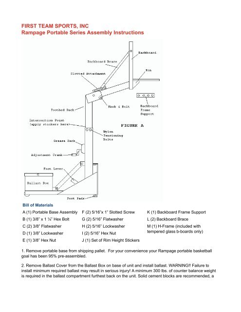
FIRST TEAM SPORTS, INC<br />
<strong>Rampage</strong> <strong>Portable</strong> <strong>Series</strong> <strong>Assembly</strong> <strong>Instructions</strong><br />
Bill of Materials<br />
A (1) <strong>Portable</strong> Base <strong>Assembly</strong> F (2) 5/16”x 1” Slotted Screw K (1) Backboard Frame Support<br />
B (1) 3/8” x 1 ¼” Hex Bolt G (2) 5/16” Flatwasher L (2) Backboard Brace<br />
C (2) 3/8” Flatwasher H (2) 5/16” Lockwasher M (1) H-Frame (included with<br />
D (1) 3/8” Lockwasher I (2) 5/16” Hex Nut<br />
tempered glass b-boards only)<br />
E (1) 3/8” Hex Nut<br />
J (1) Set of Rim Height Stickers<br />
1. Remove portable base from shipping pallet. For your convenience your <strong>Rampage</strong> portable basketball<br />
goal has been 95% pre-assembled.<br />
2. Remove Ballast Cover from the Ballast Box on base of unit and install ballast. WARNING!! Failure to<br />
install minimum required ballast may result in serious injury! A minimum 300 lbs. of counter balance weight<br />
is required in the ballast compartment furthest back on the unit. Solid cement blocks are recommended, a
minimum of (10) 4”x8”x16” solid cement blocks should be placed inside the box compartment at the back of<br />
the unit. Blocks can be purchased at any home builders supply center. DO NOT PROCEED WITH<br />
ASSEMBLY UNTIL 300 LBS. OF BALLAST HAVE BEEN INSTALLED!<br />
3. Re-attach Ballast Box cover.<br />
4. Inside the box where these instructions were located you should find (2) Backboard Braces, (1) Bolt Kit<br />
and (1) Backboard Frame Support. Remove these items from the box.<br />
5. Unpackage and lay your backboard face down on your working surface. Remove and discard the plastic<br />
shipping strip located at the top of your backboard joint where the aluminum frame comes together. If you<br />
purchased a CLEAR ACRYLIC backboard (FT210, FT215 or FT220), use the same bolts, nuts, etc. to attach<br />
the steel Backboard Frame Support (K) in its place. IF YOU PURCHASED A TEMPERED GLASS<br />
BACKBOARD (FT216, or FT221), DISREGARD PART K.<br />
SUPPLEMENTAL STEP FOR TEMPERED GLASS BACKBOARDS<br />
(IF YOU HAVE AN ACRYLIC BACKBOARD SKIP IMMEDIATELY TO STEP 6)<br />
FOR TEMPERED GLASS BACKBOARDS!!! (FT216 and FT221) - WIth your shipment you should have<br />
received PART M, H-Frame backboard mount. IMPORTANT!! - Mounted inside the four rim holes in the<br />
glass, your should see (4) aluminum grommets with vinyl around them. If the grommets are missing look in<br />
the box, they may have fallen out during shipping. If the grommets are not in the backboard and cannot be<br />
located, DO NOT PROCEED. Call First Team immediately for replacements 1-888-884-6677. With rim<br />
grommets properly inserted into glass, lay H-Frame into the backside of your TEMPERED GLASS<br />
backboard as shown in Figure B. Make certain the rim holes in the H-Frame line up with the rim holes in the<br />
backboard. When you are satisfied with rim hole alignment, secure H-Frame to the top and bottom of the<br />
aluminum frame using the 5/16" hardware provided. (see Figure B) PROCEED WITH STEP 7.<br />
6. Packaged inside with your ACRYLIC backboard you should find (2) rubber gaskets. Using packaging<br />
tape, secure one gasket to the backside of your backboard aligning the holes in the gasket with the rim<br />
holes drilled in the backboard. Make sure the holes are aligned well before proceeding!<br />
7. Loosen and remove the Knob and Bolt (see Figure A) located at the end of the silver telescoping boom.<br />
Raise the extension arm up and replace the Knob and bolt so the bottom of the extension arm rests on the<br />
top of the bolt.<br />
8. Using at least four adults, lift the backboard up so that the rim holes in the backboard are in line with the<br />
rim holes in the extension arm faceplate. While two adults hold the backboard steady in place, the other two<br />
should lift up the rim and attach it using the hardware provided in the rim box. IF YOU HAVE AN ACRYLIC<br />
BACKBOARD - Remember to sandwich the other rubber gasket between the backside of the rim and the<br />
face of the backboard! Leave rim bolts finger tight for now, DO NOT TIGHTEN RIM HARDWARE YET!<br />
9. Level the backboard & rim. First, make sure the base of the unit is sitting on a level surface and also<br />
make sure the base is resting on the footpads in front. If the foot pads are not contacting the floor, lower the<br />
base of the unit down by flipping the Foot Lever to the “UP” position (see Figure A for Foot Lever location). If<br />
foot pads are still not contacting floor then the foot pads may need to be adjusted, use a wrench to adjust<br />
the foot pads as needed. Next, place a level along the bottom side of the backboard, adjust the backboard<br />
and rim independently until level. (If you cannot move backboard or rim, loosen rim bolts until you can) Once<br />
the backboard and rim are BOTH level you should tighten the rim bolts. DO NOT OVERTIGHTEN RIM<br />
BOLTS!
10. Next, attach Backboard Braces to the Slotted Attachment bracket as shown in Figure A. The bracket is<br />
slotted to accommodate various backboard sizes. Your braces will be attached further back on the bracket if<br />
you have a 3’x4’ backboard or further forward if you have the larger 3’x5’ backboard. Attach braces using (1)<br />
3/8”x 1 ¼” hex bolt, (2) 3/8” flatwashers, (1) 3/8” lockwasher and (1) 3/8” hex nut. Leave finger tight for now.<br />
WARNING: It is extremely important that during step 10 and 11 you keep in mind that the backboard<br />
braces must be bent in a fashion that allows them to clear the welded ears on the silver inner boom<br />
when the extension arm is lowered to go through a door, etc. (See Operating Your <strong>Rampage</strong> <strong>Portable</strong><br />
Goal) It is best if the braces are bent at the smash line where the flat portion ends and the tube<br />
begins. If the braces are bent improperly it could result in damage to the braces when folding the<br />
extension arm down. If you have questions please call First Team 1-888-884-6677.<br />
11. Using (2) 5/16”x 1” slotted machine screws, flatwashers, lockwashers and hex nuts, attach backboard<br />
braces to backboard using the pre-drilled attachment holes located on the sides of your backboard. Bend<br />
braces as necessary keeping in mind the above warning. Tighten all brace attachment hardware.<br />
12. Before proceeding check to make sure your tubular backboard braces discussed in steps 10 & 11 do not<br />
interfere with the ability to lower down the extension arm. To lower extension arm remove the knob located<br />
on the side of the welded ears connected to the extension arm (Figure A). While holding on to the bottom of<br />
the backboard lift slightly while a second person slides the bolt out releasing the backboard to come down to<br />
storage position. As you CAREFULLY lower the backboard, observe the backboard braces. Are they<br />
clearing the silver ears? If not, re-bend them to compensate until they fully clear and return backboard to its<br />
upright position. Replace bolt and knob.<br />
13. Attach upper and lower padding. Attach the lower base padding by sliding the sewn vinyl tabs through<br />
the slotted holes located on the lower base shielding. Attach the upper post padding by wrapping around<br />
and securing velcro on backside of post.<br />
14. If you purchased backboard padding for your backboard, attach it now following the instruction provided<br />
in the backboard padding box.<br />
15. Check backboard level again. If it is slightly out of level, moderate adjustments can be made by slightly<br />
raising or lowering the foot pads.<br />
16. You can now apply the various height stickers to the backside of the Inner Boom. Each sticker can be<br />
positioned next to the Rack welded on the backside of the Inner Boom. Measure the rim height at each<br />
position with a measuring tape and apply the appropriate sticker using the intersection between the Inner<br />
Boom and the Outer Boom as a reference point. (See Figure A)<br />
17. Check over entire unit making sure all hardware is tightened and secure. <strong>Assembly</strong> of your <strong>Rampage</strong><br />
portable goal is complete! Keep these assembly instructions for future reference. Also, carefully read and<br />
follow the instructions provided under “Operating and Maintenance of your <strong>Rampage</strong> <strong>Portable</strong> Goal.”
Operating Your <strong>Rampage</strong> <strong>Portable</strong> Goal<br />
Adjusting the rim height: Adjusting the rim height is simple. Simply turn the adjustment crank to raise the<br />
goal height, or reverse the cranking motion to lower the goal height.<br />
ATTENTION: DO NOT ADJUST UNIT ABOVE THE 10’ PLAYING HEIGHT OR BELOW 6’6”!!!! DOING<br />
SO MAY RESULT IN DAMAGE TO YOUR UNIT NOT COVERED UNDER WARRANTY!<br />
Moving the unit: First, lower the rim height down to approximately 6 ½’. To move the unit, simply step on<br />
the “Foot Lever” (see Figure A). This will raise the unit onto the front rolling castor wheel. Roll unit by<br />
pushing on the backboard directly below the rim and steer the unit by guiding the extension arm left or right.<br />
Once, you have reached the desired location flip the “Foot Lever” up and the unit will lower onto the foot<br />
pads.<br />
Moving unit through/under a doorway: Follow the instructions listed above for moving the unit. Once you<br />
reach the doorway, drop the backboard down by removing the knob and bolt that go through the silver<br />
extension. Carefully lower backboard down to its lowest point. Now the unit may be rolled through the<br />
doorway. Raise the backboard and replace bolt and knob. NOTICE: Double-wide doors are necessary to<br />
allow unit to pass through doorway.<br />
Maintaining Your <strong>Rampage</strong> <strong>Portable</strong> Goal<br />
Though your <strong>Rampage</strong> portable goal is designed and coated to withstand the elements, it is not advisable to<br />
leave the goal system outdoors for extended periods of time. If this cannot be avoided follow these steps to<br />
increase the life of the unit.<br />
1. Grease the gear rack welded on the backside of the silver telescoping boom.<br />
2. Grease the crank gears. There is a grease zerk located on the crank casing (see figure A). Note: Crank<br />
gears should be greased as needed regardless of whether the unit is left outdoors.<br />
3. Keep unit covered when not in use. Use of a tarp or other waterproof cover similar to a grill cover, this will<br />
help keep the unit dry and prevent rust.<br />
Additionally, check all bolts and nuts periodically to make sure they are tight and secure. Following these<br />
simple points will keep your <strong>Rampage</strong> portable goal in top operating condition season after season.<br />
FIRST TEAM SPORTS, INC.<br />
902 COREY ROAD<br />
HUTCHINSON, KS 67501<br />
TOLL FREE: 888-884-6677