Mini Band Saw / Mini Sierra para Huesos
Mini Band Saw / Mini Sierra para Huesos
Mini Band Saw / Mini Sierra para Huesos

You also want an ePaper? Increase the reach of your titles
YUMPU automatically turns print PDFs into web optimized ePapers that Google loves.
WAREHOUSE<br />
71 Bloomfield Ave<br />
Newark, NJ 07104<br />
Phone: 973 482 5070<br />
Fax: 973 482 0725<br />
Cell: 973 985 8239<br />
Fax: 305 866 2704<br />
TOLL FREE<br />
800 445 6601<br />
www.skyfood.us<br />
commercial@skyfood.us<br />
OFFICE<br />
12550 Biscayne Blvd.<br />
Suite 800-3<br />
North Miami, FL 33181<br />
Phone: 305 868 1603<br />
Fax: 305 866 2704<br />
Instruction Manual /<br />
Manual Instrucciones<br />
<strong>Mini</strong> <strong>Band</strong> <strong>Saw</strong> /<br />
<strong>Mini</strong> <strong>Sierra</strong> <strong>para</strong> <strong>Huesos</strong><br />
/<br />
UG 0024 - April/2010
SUMMARY / INDICE<br />
1. ENGLISH 01<br />
2. ESPAÑOL 09<br />
/
Summary<br />
01 Main Precautions<br />
0 2 Main Components<br />
03 Technical data<br />
04 Installation<br />
05 Pre Operation<br />
06 Operation<br />
07 Components Adjustment<br />
7.1 Pulley Belts<br />
7.2 Superior Bearing<br />
7.3 Cutting Regulator<br />
08 Cleaning<br />
09 General Advices<br />
10 Electrical Diagram<br />
1<br />
2<br />
3<br />
4<br />
4<br />
5<br />
6<br />
6<br />
6<br />
7<br />
7<br />
8<br />
8<br />
8
NOTICE TO OWNERS AND OPERATORS<br />
The MSK and MSKL <strong>Mini</strong> <strong>Band</strong> <strong>Saw</strong>s are designed to cut food products safely<br />
and efficiently. Unless the operator is properly trained and supervised, however,<br />
there is the possibility of a serious injury. It is the responsability of the owner to<br />
assure that this machine is used properly and safely, strictly following the<br />
instructions contained in this Manual and any requirements of local law.<br />
1 Main Precautions<br />
When incorrectly used the MSK and MSKL are potentially dangerous machines.<br />
Cleaning, maintenance or service must always be done by experienced operators, and with<br />
the machine disconnected from the electricity supply.<br />
NEVER use tools not belonging to the machine to help operation.<br />
KEEP hands off the moving parts of the machine.<br />
NEVER connect the power source with wet hands or wet clothes.<br />
ALWAYS ground the machine properly<br />
NEVER touch the blade No.06 (picture 01) even when it is not in use because its<br />
edge is very sharp, it can cause serious cuttings.<br />
NEVER adjust the cutting regulator (optional) No.12 (picture 01) with the blade in<br />
motion.<br />
NEVER use clothes with loosen sleeves specially near the wrist during the cutting<br />
operation.<br />
USE steel gloves during the cutting operation.<br />
NEVER switch on the machine with one of its doors opened<br />
NEVER spray water or other liquid substances directly at motor, power switch or<br />
any other electrical components.<br />
KEEP your working area clean and dry to prevent it from becoming sllipery.<br />
ALWAYS install equipment in working area with adequate light and space away<br />
from CHILDREN and visitors.<br />
NEVER operate without all warning labels attached and owner/operator manual<br />
available to operator.<br />
NEVER leave unattended while operating.<br />
STOP the machine immediately if you hear abnormal noises, of fear that injuries<br />
may occur.<br />
CONTACT your Distributor if you have any problems with the installation and<br />
operation of this machine.<br />
2
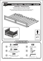
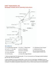
2 MAIN COMPONENTS<br />
Picture - 01<br />
01 09<br />
02<br />
03<br />
04<br />
05<br />
06<br />
07<br />
08<br />
01- Blade Calibrator Knob<br />
02- Wheels Diameter 225 MSK / MSKL<br />
03- ON/OFF Switch.<br />
04- Frame.<br />
05- Blade Guide.<br />
06- Blade.( Width ½”)<br />
07- Fixed Table.<br />
08- Complete Movable Table (Optional).<br />
09- Staple.<br />
10- Upper Door.<br />
11- Complete Pusher (Optional).<br />
12- Complete Cutting Regulator (Optional).<br />
13- Lower Door.<br />
14- Handle.<br />
15- Locking Knob M8x30mm.<br />
16- Handle f 1/2“-CRW.<br />
3<br />
15<br />
10<br />
14<br />
16<br />
11<br />
12<br />
14<br />
13<br />
02<br />
Complete Scraper
All returned goods are subject to a 20% handling/restocking fee. All returns must be returned in their original<br />
packaging and within thirty (30) days from the shipping date.<br />
SKYFOOD reserves the right to change the design and specifications of its equipment or any related<br />
documentation at any time. The end user is not entitled to upgrades nor refunds resulting from these<br />
changes.<br />
Updates<br />
nd<br />
These Terms and Conditions were last updated on February 02 , 2010.<br />
SKYFOOD'S LIMITED WARRANTY<br />
All new products FLEETWOOD BY SKYMSEN, sold by SKYFOOD EQUIPMENT, LLC. (“SKYFOOD”), for use<br />
only in the continental Unites States (collectively, “Products” or singularly, “Product”), are warranted to be free<br />
from defects in materials and workmanship for a period of one (1) year from the date of purchase by the original<br />
purchaser/user (“End User”). No warranty is given or implied to a subsequent transferee or any other third party.<br />
This warranty is expressly conditional upon SKYFOOD being notified of any defects in materials or workmanship<br />
within five (5) days of its occurrence, within the warranted time period. If a notice of a claim under this warranty is<br />
timely made by the End User, SKYFOOD or a designated service company (“Service Company”), will repair the<br />
Product or replace the part which is defective, subject to the additional conditions hereinafter described.<br />
This warranty shall not apply if damage occurs from improper installation, wrong voltage, nor to the extent that<br />
Products or parts have been used other than in conformance with operating and maintenance instructions,<br />
subjected to misuse or abuse or damaged by accident, acts of God, abnormal use or stress or any other matter<br />
unrelated to SKYFOOD, and beyond its reasonable control. In addition, this warranty does not cover normal<br />
wear and tear of certain items, such as, but not limited to, blades, stones, chopper cutting knives, plates, slicing<br />
knives, cutting disc, gaskets, oil changes, sealing tape, heat seal wires, worm gears, and other parts expendable<br />
by nature and that need to be replaced frequently. THIS WARRANTY EXCLUDES ALL ORAL, STATUTORY,<br />
EXPRESS OR IMPLIED WARRANTIES WHICH MAY BE APPLICABLE TO SKYFOOD, INCLUDING, BUT<br />
NOT LIMITED TO, ANY IMPLIED WARRANTY OF MERCHANTABILITY AND FITNESS FOR PARTICULAR<br />
PURPOSE. Under no circumstances shall SKYFOOD be liable for loss of use, revenue or profit or for incidental<br />
or consequential damages. The sole and exclusive remedy for breach of any warranty is limited to the<br />
remedies provided in the <strong>para</strong>graph above.<br />
Products weighing less than seventy (70) lbs. must be taken or shipped, shipping charges prepaid, either to<br />
SKYFOOD's facility or a SKYFOOD's designated service company (“Service Company”). SKYFOOD offers a<br />
limited on-site warranty only for Products whose weight exceeds seventy (70) lbs., provided they are<br />
installed in a location that is within a thirty (30) mile radius of a Service Company. In this case, warranty<br />
services will be provided during regular business hours.<br />
This warranty shall not take effect unless and until a properly completed and executed WARRANTY<br />
REGISTRATION form has been received by SKYFOOD EQUIPMENT, LLC, within thirty (30) days from the date<br />
of purchase. The WARRANTY REGISTRATION is available either in the Instruction Manual of every Product or<br />
at SKYFOOD's website www.skyfood.us.<br />
The End User must fulfill the WARRANTY REGISTRATION form and<br />
send it to SKYFOOD according to the instructions posted on the referred website. Failure to do so will void the<br />
warranty.<br />
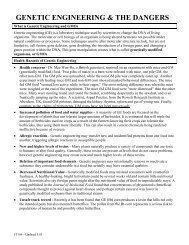
3 TECHNICAL DATA<br />
4 INSTALLATION<br />
Table - 01<br />
Technical Data Units MSK MSKL<br />
Voltage<br />
110 / 220 (*) 110 / 220 (*)<br />
Frequency<br />
Rating<br />
Consuption<br />
Height<br />
Width<br />
Depth<br />
Net Weigth<br />
50 or 60 50 or 60<br />
Gross Weigth<br />
Cutting Width<br />
Cutting Heigth<br />
A = 700mm (Without Cutting Regulator)<br />
A = 1200mm (with Cutting Regulator)<br />
[V]<br />
[Hz]<br />
[Hp]<br />
[kW/h]<br />
[mm]<br />
[mm]<br />
[mm]<br />
[kg]<br />
[kg]<br />
[mm]<br />
4<br />
[mm]<br />
* All machines are wired for voltage as ordered.<br />
0,5 0,5<br />
0,26 0,26<br />
930 930<br />
650 650<br />
600 600<br />
43 43<br />
52 52<br />
215 215<br />
250<br />
250<br />
The mini band saws have to be installed on a working surface with a recommended<br />
heigth of 850mm. The surface length should be 120cm (with cutting regulator) or<br />
70cm(without cutting regulator).<br />
Grounding wire must always be connected.<br />
IMPORTANT: Check the tension of the blade by turning the handle No.01<br />
(picture 01) clockwise before operating it.<br />
850mm<br />
A<br />
700mm
5 PRE OPERATION<br />
Check if the machine is firm, no movement is allowed on the supporting surface .<br />
Wash with warm water and soap all the food-contact parts, and wipe dry. To do it<br />
proceed as follows (the reference numbers below are those of the picture 01):<br />
a) First of all switch the machine off and disconnect it from the power source ;<br />
b) Open the upper door No.10 and lower door No.13 by pulling the handle No.15;<br />
c) Loosen the blade No.06 turning the handle No.01 or calibrator (optional)<br />
clockwise and take it out from the upper and lower wheels No.02;<br />
d) Take out the staples which are in front of the upper and lower wheels to be able to<br />
pull them out;<br />
e) Assemble the components following the inverse steps.<br />
IMPORTANT: The blade must be well calibrated. Use the handle No.01<br />
turning it clockwise to get the right tension of the blade. Keep the machine off to<br />
adjust the cutting regulator.<br />
5<br />
In case the machine is equipped<br />
with the blade tension calibrator<br />
(optional) the same as the handle<br />
No.01, you must turn it until the<br />
blade starts escaping, it means<br />
that the blade has the right<br />
tension.<br />
SKYFOOD EQUIPMENT LLC - SERVICE<br />
Parts and services are available from the address indicated herein. Parts can be combined with finished<br />
goods order or by itself.<br />
SKYFOOD EQUIPMENT LLC – Warehouse<br />
71 BLOOMFIELD AVE - NEWARK, NJ 07104 - USA - Phone: 973 482 5070 - Fax: 973 482 0725 - TOLL<br />
FREE 800 445 6601<br />
Terms of Sale<br />
TERMS AND CONDITIONS OF SALE<br />
Purchase of any products sold by SKYFOOD shall be subject to and expressly limited by the terms and conditions<br />
contained herein. No changes to, waiver of, or addition to any of these terms and conditions shall be effective<br />
unless agreed to in writing and signed by SKYFOOD. Buyer acknowledges and agrees that these terms and<br />
conditions supersede the terms and conditions of any purchase order or other documentation used by Buyer and,<br />
except for delivery and billing addresses, and quantities prices and items ordered, any conflicting or additional<br />
terms are void and have no effect, but that Buyer may place orders by use of purchase orders and other<br />
documentation for its convenience purposes only. Notwithstanding the foregoing, SKYFOOD reserves the right at<br />
any time to amend these terms and conditions, and Buyer shall be deemed to accept such amended terms and<br />
conditions by ordering products herein offered after the date of such amendment. Additional special terms and<br />
conditions of SKYFOOD may be applicable with respect to certain products.<br />
Orders Acceptance<br />
All orders from Buyers, whether solicited and written by either a SKYFOOD EQUIPMENT, LLC (“SKYFOOD”)<br />
Sales Representative, distributor or dealer, are deemed offerings to purchase until accepted by SKYFOOD.<br />
SKYFOOD reserves the right to accept orders in full or in part. Acceptance may be either by written confirmation or<br />
shipment of the order, in full or in part.<br />
Shipping<br />
TERMS – All prices are FCA (Free Carrier) shipping point. Unless express instructions in writing are received<br />
from the Buyer, SKYFOOD has complete freedom in choosing the means, route and procedure to be followed in<br />
the handling, transportation and delivery of the goods. SKYFOOD will advance the shipping costs on behalf of the<br />
Buyer and charge it accordingly. SKYFOOD shall under no circumstances be liable for any loss, damage,<br />
expense or delay to the goods for any reason whatsoever when said goods are in the custody, possession or<br />
control of third parties selected by SKYFOOD to forward, enter, clear, transport, or render other services with<br />
respect to such goods. Please, inspect your unit upon arrival at the destination and report any transit damage to<br />
SKYFOOD and to the shipping company, in order to initiate a claim with the latter. Claims must be reported to the<br />
transportation company within fifteen (15) days as of the date of the invoice.<br />
Free Shipping<br />
Orders of $4,000.00 or more, with a minimum of 2 pieces (mixed or match), shipped to the same address in the<br />
continental United States will have free shipping.<br />
Tax Information<br />
Any tax, duty, custom or other fee of any nature imposed upon the products, their sale, transportation, delivery,<br />
use or consumption shall be paid by Buyer in addition to the price quoted or invoiced. If SKYFOOD is required to<br />
prepay any such tax or fee, Buyer will reimburse SKYFOOD. Buyer must provide SKYFOOD with a<br />
resale/exemption certificate in order to avoid the withholding of applicable taxes.<br />
Interest<br />
Past due balances are subject to a interest charge of 1.5% per month or the highest rate permitted by law,<br />
whichever is lower, until paid.<br />
Return Policy<br />
All returns are subject to the prior authorization of SKYFOOD, in its discretion. Buyer must contact Buyer Support<br />
at (305) 868-1603, or by fax at (305) 866-2704, or via e-mail at commercial@skyfood.us<br />
in order to request a<br />
Return Authorization number (“RA”) providing, along with the identification of the goods, a specific reason for<br />
return. Buyer Support will either authorize or deny the request for return. Only NEW and UNUSED items are<br />
acceptable for return. Unauthorized returns will be destroyed and no credit issued. All authorized returned goods<br />
must be shipped freight prepaid to SKYFOOD.
5.2.3 Ajuste Del Regulador de Corte:<br />
El Regulador de Corte No.12 (Foto 01) (opcional) fu desarrollado <strong>para</strong><br />
proveer cortes con el mismo espesor y también <strong>para</strong> proteger el usuario de accidentes.<br />
Para ajustar el Regulador de Corte:<br />
Gire la manipula de fijación No.16 (Foto 01) en el sentido anti-horario <strong>para</strong><br />
poder mover el Regulador de Corte <strong>para</strong> la izquierda o <strong>para</strong> la derecha conforme lla distancia<br />
que Usted desea dejar desde el Regulador hasta la hoja.<br />
Después de ajustado gire la manipula de fijación No.16 (Foto 01) en el sentido<br />
horario <strong>para</strong> fijar el Regulador de Corte en la posición deseada.<br />
5.3Diagrama Eléctrico Mod. MSK y MSKL<br />
21<br />
6 OPERATION<br />
(The reference numbers below are those of the picture 01).<br />
Switch on the machine pressing the on/off switch No.03.<br />
Put the product to be processed onto the fixed table No.07 or onto the movable table<br />
(optional) No.08, pushing it to the direction of the blade lined up by the cutting regulator<br />
(optional) No. 12, maintaining the thickness of the slice desired.<br />
When pulling back the product do not touch the blade avoiding disconnecting it from<br />
the wheels.<br />
Drop a little bit of water onto the fixed table to facilitate the slipping of the product.<br />
7 COMPONENTS ADJUSTMENT<br />
7.1 Pulley Belt (the reference numbers below are those of the picture 02):<br />
The belt No.05 must be firmly fixed to prevent it from skiding. Do not tighten it too<br />
much because it can wear out quickly.<br />
To have access to the belt remove the screws with a screwdriver from the inferior<br />
back lid and take it out.<br />
With a screw-wrench No.02 loosen the screws No.01 turning it counter-clockwise.<br />
To stretch out the belt you have to push the motor No.04 with the wood lever No.03 tightening<br />
the screws.<br />
IMPORTANT: The pulleys must be lined up.<br />
Picture - 02<br />
03 04 05<br />
6<br />
01<br />
02
7.2 Upper bearing adjustments:<br />
The purpose of this adjustment is to centralize the blade on the gear and avoid it<br />
falling down.<br />
First of all disconnect the machine from the electricity supply. Then loosen blade<br />
No.06(picture 01) turning handle No.01 (picture 01) counter-clockwise.<br />
Take out upper back lid by removing screws using the screwdriver. Loosen the<br />
three screw-nuts No.01(picture 03) using a 10mm screw-wrench.<br />
Using the screwdriver turn the screw-nut No.02 (picture 03) ¼ counter -clockwise if<br />
t h e w h e e l i s i n c l i n e d t o w a r d s t h e f r o n t o r t u r n i t ¼<br />
clockwise if it is inclined backwards. Tighten the three screw-nut No.01(picture 03)<br />
previously loosen. Calibrate the blade according to pre-operation (5).<br />
Turn the wheels manually to check if the blade is centralized, if it is not keep turning<br />
the wheels until the blade is centralized.<br />
Picture - 03<br />
01<br />
02 03<br />
7.3 Cutting Regulator:<br />
The cutting regulator No.12 (picture 01) (optional) was designed to provide cuts<br />
with the same thickness and also to protect the operator from getting injured.<br />
To adjust the cutting regulator proceed as follows:<br />
Turn locking knob No.15 (picture 01) counter-clockwise to be able to move the<br />
cutting regulator to the left and right according to the distance you want to leave from it to the<br />
blade.<br />
Then turn the locking knob No.15 (picture 01) clockwise to fix the cutting regulator<br />
in the desired position.<br />
7<br />
OBSERVACIÓN<br />
Al hacer el ajuste de las correas , verifique también el alineamiento de las poleas .<br />
Con un destornillador , saque los tornillos que fijan la tapa trasera inferior y retírela<br />
, <strong>para</strong> tener acceso a las poleas . Usando una llave de tuerca ( 9/16" ) No. 02 (Foto 05) afloje los<br />
tornillos No.01 (Foto 05 ) girándolos en sentido anti-horario . En seguida con el auxilio de una<br />
palanca de madera No.03 (Foto 05) , empuje el motor en el sentido que provoque una mayor tensión<br />
de las Correas No. 05 (Foto 05) , después apriete los tornillos No.01 (Foto 05) .<br />
FOTO - 02<br />
Foto - 06<br />
03 04 05<br />
5.2.2 Ajuste del Cojinete Superior No.03 (Foto 06):<br />
El propósito de este ajuste es centralizar la hoja en el volante y evitar que la misma<br />
salte afuera de el.<br />
Primero desconecte la maquina de la red eléctrica. Después afloje la hoja No.06<br />
(Foto 01) girando el manipulo No.01 (Foto 01) en el sentido anti-horario.<br />
Retire la tapa trasera superior removiendo los tornillos con un destornillador.<br />
Afloje las tres tuercas No. 01 (Foto 06) usando una llave de tuerca de 10mm.<br />
Usando un destornillador gire el tornillo superior No.02 (Foto 06) ¼ de giro en el<br />
sentido anti-horario si la lamina estuviera desplazada <strong>para</strong> adelante o gire el tornillo superior No.02<br />
(Foto 06) ¼ de giro en el sentido horario si la lamina estuviera desplazada <strong>para</strong> tras.<br />
Apriete las tres tuercas No.01 (Foto 06) previamente aflojadas.<br />
Calibre la tensión de la hoja como explicado en Pre-Operación , ítem 2.2 .<br />
Gire el volante con las manos <strong>para</strong> averiguar si la hoja esta centralizada en el<br />
volante. Si ella no está centralizada, continúe girando el volante hasta que la hoja se centralice .<br />
01<br />
01<br />
02<br />
02 03<br />
20
Problemas Causas Soluciones<br />
* La maquina liga, pero<br />
cuando el producto entra en<br />
contacto con la hoja, la<br />
misma <strong>para</strong> o gira en baja<br />
Rotación.<br />
* H o j a s e r o m p e<br />
* Hoja patinando sobre el<br />
volante<br />
* Hoja soldada de forma<br />
incorrecta<br />
5.2 AJUSTE Y SUBSTITUICIÓN DE COMPONENTES<br />
* Haga la calibración de la hoja de<br />
acuerdo con el ítem 2.2<br />
* Hoja o volante sucio * Hacer limpieza de acuerdo con ítem<br />
* Volantes con defectos<br />
* Dificultades en el corte del * Hoja o volante sucio * Hacer limpieza de acuerdo con ítem<br />
3.2<br />
*Hoja fuera del centro de los * Hacer ajuste en el cojinete superior de<br />
acuerdo con ítem 5.2.2 deste manual, o<br />
en casos mas graves llame a su<br />
revendedor .<br />
5.2.1 Correa de transmisión<br />
Para garantizar un buen funcionamiento de la maquina y una vida longa<br />
de las correas , estas deben estar bien reguladas . Caso se queden flojas , las correas<br />
iran patinar durante la operación .<br />
También debe se cuidar <strong>para</strong> que ellas no trabajen bajo demasiada<br />
tensión , pues en esta condición causarán desgaste prematuro en los rodamientos .<br />
Para el ajuste de las correas procedase como sigue :<br />
19<br />
* Ajuste la tensión de la correa de<br />
acuerdo con el ítem 5.2<br />
* Llame a su revendedor<br />
8 CLEANING<br />
First of all disconnect the machine from power source. (All the numbers mentioned below<br />
are those of Picture - 01).<br />
- Remove the upper door No.10 by unscrewing the screws of the hinges<br />
- Remove the lower door No.13 doing as above<br />
- Remove the<br />
blade by turning blade calibrator knob No.01 counter-clockwise, then loosen the blade and<br />
pull it out<br />
- Take out upper and lower wheels No.05 by pulling staples out No.09, which are located in<br />
front of the wheels<br />
- Never use hard tools such as: knives, forks, hooks, or others to remove sticked pieces of<br />
cut meat from the upper and lower doors. To do that use a plastic brush.<br />
- Assemble the components following the inverse steps.<br />
NOTE: The sharp edge of the blade must be facing the front of the machine.<br />
All removable components must be washed with warm water and neutral soap. Be careful<br />
when washing the blade. It has a sharp edge that could cause serious irre<strong>para</strong>ble injuries to<br />
the hands.<br />
CAUTION: The machine is not protected against water jets. Do not clean it with steam<br />
jets, or high pressure blasts or similar methods. Under no circumstances should the<br />
MSK and MSKL be hose rinsed as this may result in short circuit or serious damage to<br />
the machine.<br />
Clean the body of the machine with a damp clean cloth and wipe dry.<br />
9 GENERAL ADVICES<br />
ALWAYS turn machine off before cleaning and maintenance.<br />
PROVIDE enough space around machine to avoid breakings.<br />
ALWAYS keep the floor dry. Wet floors may cause slippings.<br />
ALWAYS turn machine off in case of power supply lack.<br />
NEVER let dust or water to get into electrical and mechanical components of<br />
the machine.<br />
DO NOT modify original features of the machine.<br />
DO NOT take out nor tear off any safety or identification label.<br />
10 ELECTRIC DIAGRAM MOD. MSK and MSKL<br />
8
1. INTRODUCCIÓN 10<br />
1.1 Seguridad 10<br />
1.2 Componentes Principales<br />
1.3 Características Técnicas<br />
2. Instalación Y Pre-operación<br />
2.1 Instalación<br />
2.2 Pre- Operación<br />
3. Operación<br />
INDICE<br />
3.1 Procedimiento <strong>para</strong> la Operaciòn<br />
3.2 Limpieza<br />
4. Nociones Generales De Seguridad<br />
4.1 Practicas Basicas de Operación<br />
4.2 Cuidados Y Observaciones Antes de Ligar la Maquina<br />
4.3 Inspección de Rutina<br />
4.4 Operación<br />
4.5 Despues de Terminar el Trabajo<br />
4.6 Manutención<br />
4.7 Avisos<br />
5. Analisis Y Resolución de Problemas<br />
5.1 Problemas, Causas Y Soluciones 18<br />
5.2 Ajuste Y Substituición de Componentes<br />
19<br />
5.3 Diagrama Eléctrico Mod. MSK Y MSKL<br />
21<br />
9<br />
10<br />
12<br />
12<br />
12<br />
13<br />
13<br />
13<br />
14<br />
15<br />
15<br />
16<br />
17<br />
17<br />
17<br />
18<br />
18<br />
18<br />
4.6 Manutención<br />
4.6.1 Peligros<br />
Con la maquina ligada cualquier operación de manutención es peligrosa .<br />
DESLÍGUELA FÍSICAMENTE DE LA RED ELÉCTRICA , DURANTE TODA LA<br />
OPERACIÓN DE MANUTENCIÓN .<br />
4.7 Avisos<br />
La manutención eléctrica o mecánica debe ser hecha por una persona<br />
calificada <strong>para</strong> hacer el trabajo .<br />
La persona encargada por la manutención debe certificarse que la maquina<br />
trabaje bajo condiciones TOTALES DE SEGURIDAD .<br />
5. Problemas , Causas y Soluciones<br />
5.1 Problemas , Causas y Soluciones<br />
Las <strong>Mini</strong> <strong>Sierra</strong>s (Mod MSK y MSKL) , fueran diseñadas <strong>para</strong> que necesiten un<br />
mínimo de manutención . Sin embargo pueden ocurrir algunas irregularidades en su funcionamiento ,<br />
debido al desgaste natural causado por su uso .<br />
Caso haya algún problema con su maquina , verifique la Tabla 02 abajo , donde<br />
están indicadas algunas soluciones recomendadas .<br />
* La maquina no liga<br />
Tabla - 02<br />
Problemas Causas Soluciones<br />
* Olor de quemado o<br />
humo<br />
* La maquina esta desconectada<br />
de la red eléctrica.<br />
* Falta de Energía<br />
Eléctrica<br />
* Problema con el motor o<br />
otros circuitos eléctricos<br />
18<br />
* Ligue el cable eléctrico de la<br />
maquina en la red eléctrica<br />
* Averigüe si hay energía eléctrica<br />
* Llame a su revendedor
4.3 Inspección de Rutina<br />
4.3.1 Aviso<br />
Al averiguar la tensión de las correas , NO coloque los dedos entre las<br />
correas y las poleas .<br />
4.3.2 Cuidados<br />
Verifique los motores y las partes deslizantes o girantes de la maquina , con<br />
relación a ruidos anormales .<br />
Verifique la tensión de las correas , y sustituya el conjunto , caso alguna correa<br />
o polea tenga desgaste . Al verificar la tensión de las correas , NO coloque los dedos entre la s<br />
correas y poleas.<br />
Verifique las protecciones y los dispositivos de seguridad <strong>para</strong> que siempre<br />
funcionen adecuadamente .<br />
4.4 Operación<br />
4.4.1 Avisos<br />
No trabaje con pelo largo , que pueda tocar cualquier parte de la maquina ,<br />
pues el mismo podría causar serios accidentes . Amarrelo <strong>para</strong> arriba y <strong>para</strong> atrás , o cubralo<br />
con un pañuelo .<br />
Solamente operadores entrenados y calificados pueden operar la maquina .<br />
Nunca toque con las manos o de cualquier otra manera , partes girantes de la<br />
maquina.<br />
JAMÁS opere la maquina , sin algún de sus accesorios de seguridad.<br />
4.5 Después de Terminar el Trabajo<br />
4.5.1 Cuidados<br />
Siempre limpie la maquina . Para tanto , deslíguela físicamente del soquete .<br />
Nunca limpie la maquina antes de su PARADA COMPLETA.<br />
Recoloque todos los componentes de la maquina en sus lugares , antes de<br />
ligarla otra vez.<br />
Al verificar la tensión de las correas, NO coloque los dedos entre las correas y<br />
las poleas.<br />
17<br />
1. INTRODUCCIÓN<br />
1.1 SEGURIDAD<br />
Cuando usada incorrectamente , la <strong>Sierra</strong> <strong>para</strong> <strong>Huesos</strong> (Mod. MSK y MSKL) es<br />
una maquina potencialmente PELIGROSA . La manutención , la limpieza o otra cualquier actividad<br />
de servicio , solamente deben ser hechas por personas debidamente entrenadas , y con la maquina<br />
desconectada de la red eléctrica .<br />
Las instrucciones abajo deberán ser seguidas <strong>para</strong> evitar accidentes :<br />
1.1.1 Desconecte la maquina de la red eléctrica cuando sea deseado retirar<br />
cualquier parte removible , <strong>para</strong> hacer la limpieza , la manutención o otro cualquier servicio.<br />
1.1.2 Nunca usar instrumentos fuera a los que acompañan la maquina <strong>para</strong> auxiliar<br />
en su operación .<br />
1.1.3 Nunca toque la hoja No.6 (Foto 01), mismo con la maquina desligada, pues la<br />
misma posee un lado cortante.<br />
1.1.4 Nunca ajuste el Regulador de Corte No.12 (Foto 01), con la hoja en<br />
movimiento.<br />
1.1.5 Nunca use chorros de agua directamente sobre la maquina .<br />
1.1.6 Nunca use ropas con mangas anchas , principalmente en los puños , durante<br />
la operación .<br />
1.1.7 Use guantes de acero durante la operación.<br />
1.1.8 Mantenga las manos lejos de las partes movibles.<br />
1.1.9 Nunca ligue la maquina con las manos, los zapatos o ropas mojadas.<br />
1.1.10 Nunca ligue la maquina con una de sus puertas abiertas .<br />
1.1.11 Cuando se haga la instalación de la maquina no sea olvidado de hacer la<br />
conexión de tierra .Una buena conexión a la tierra es importante <strong>para</strong> la seguridad suya y del equipo .<br />
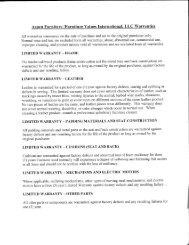
1.2 PRINCIPALES COMPONENTES<br />
Todos los componentes que incorporan la maquina son construidos con materiales<br />
cuidadosamente seleccionados <strong>para</strong> su función , dentro de los padrones de prueba y de la experiencia<br />
de SIEMSEN .<br />
10
Foto 01<br />
Foto 2<br />
01 09<br />
02<br />
03<br />
04<br />
05<br />
06<br />
07<br />
08<br />
14<br />
01 Manipula de control de tensión de la hoja<br />
02 Volante - diámetro 225<br />
03 Llave Liga/Desliga<br />
04 Estructura05 Guía de la hoja<br />
06 Hoja ( Ancho ½”)<br />
07 Mesa Fija<br />
08 Mesa Movible Completa (opcional)<br />
09 Clavillo Traba<br />
11<br />
16<br />
10<br />
15<br />
17<br />
11<br />
12<br />
15<br />
13<br />
02<br />
10 Puerta Superior<br />
11 Empujador Completo (opcional)<br />
12 Regulador de Corte Completo (opcional)<br />
13 Puerta Inferior<br />
14 Llave selectora de voltaje<br />
15 Manipula de las puertas<br />
16 Manipula de fijación del Regulador de Corte<br />
17 Esfera<br />
Rascador Completo<br />
Codigo 13299.3<br />
4.1.3 Avisos<br />
En el caso de falta de energía eléctrica , desligue inmediatamente la llave<br />
liga/desliga.<br />
Use solamente óleos lubrificantes o grasas recomendadas o equivalentes .<br />
Evite choques mecánicos , ellos pueden causar fallas o malo funcionamiento .<br />
Evite que agua , suciedad o polvo entren en los componentes mecánicos y<br />
eléctricos de la maquina .<br />
NO ALTERE las características originales de la maquina .<br />
NO SUCIE , RASGUE O RETIRE CUALQUIER ETIQUETA DE<br />
SEGURIDAD O DE IDENTIFICACIÓN . Caso alguna esté ilegible o perdida, solicite otra al<br />
Asistente Técnico mas cercano .<br />
LEA ATENTAMENTE Y CON CUIDADO LAS ETIQUETAS DE<br />
SEGURIDAD Y DE IDENTIFICACIÓN CONTENIDAS EN LA MAQUINA , ASÍ COMO<br />
LAS INSTRUCCIONES Y LAS TABLAS TÉCNICAS CONTENIDAS EN ESTE MANUAL.<br />
4.2 Cuidados y Observaciones Antes de Ligar la Maquina .<br />
IMPORTANTE :<br />
Lea con atención y cuidado las INSTRUCCIONES contenidas en este Manual, antes de<br />
ligar la maquina . Certifiquese que entendió correctamente todas las informaciones . En<br />
caso de duda , consulte su superior o el Revendedor .<br />
4.2.1 Peligro<br />
Cables o hilos eléctricos con aislamiento dañado , pueden provocar choques<br />
eléctricos . Antes de usarlos verifique sus condiciones .<br />
4.2.2 Avisos<br />
Esté seguro que las INSTRUCCIONES contenidas en este Manual, estén<br />
completamente entendidas . Cada función o procedimiento de operación y de manutención<br />
debe estar perfectamente claro .<br />
El accionamiento de un comando manual ( botón, llave eléctrica, palanca, etc.<br />
) debe ser hecho siempre después que se tenga la certitud de que es el comando correcto .<br />
4.2.3 Cuidados<br />
El cable de alimentación de energía eléctrica de la maquina , debe tener una<br />
sección suficiente <strong>para</strong> soportar la potencia eléctrica consumida .<br />
Cables eléctricos que estuvieran en el suelo cerca de la maquina , deben ser<br />
protegidos <strong>para</strong> evitar corto circuitos .<br />
16
IMPORTANTE<br />
Coloque Vaselina en el hueco de los volantes a cada 15 días. Observe la posición de la hoja<br />
<strong>para</strong> no haber inversión. Los dientes deberán quedarse <strong>para</strong> el lado de adelante de la<br />
maquina, con la inclinación <strong>para</strong> bajo.<br />
4. Nociones Generales de Seguridad<br />
Las Nociones Generales de Seguridad fueran pre<strong>para</strong>das <strong>para</strong> orientar y<br />
instruir adecuadamente a los operadores de las maquinas , así como aquellos que serán<br />
responsables por su manutención .<br />
La maquina solamente debe ser entregue al operador en buenas condiciones de uso , al que el<br />
operador debe ser orientado cuanto al uso y a la seguridad de la maquina por el Revendedor . El<br />
operador solamente debe usar la maquina con el conocimiento completo de los cuidados que<br />
deben ser tomados , después de LER ATENTAMENTE TODO ESTE MANUAL .<br />
4.1 Practicas Básicas de Operación<br />
IMPORTANTE<br />
En el caso de algun item de las NOCIONES GENERALES DE SEGURIDAD no<br />
ser aplicable en su producto, por favor desconsiderar el mismo.<br />
4.1.1 Peligros<br />
Algunas partes del accionamiento eléctrico presentan pontos o terminales<br />
con altos voltajes . Cuando tocados pueden ocasionar graves choques eléctricos , o hasta la<br />
muerte de una persona .<br />
Nunca toque un comando manual ( botón , llave eléctrica , etc. ) con las manos<br />
, zapatos o ropas mojadas . No obedecer esta recomendación , también podrá provocar choques<br />
eléctricos , o hasta la muerte de una persona .<br />
4.1.2 Advertencias<br />
El local de la llave liga/desliga debe ser bien conocido , <strong>para</strong> que sea posible<br />
accionarla a cualquier momento sin la necesidad de procurarla .<br />
Antes de qualquer tipo de manutenção, desligue fisicamente a máquina da<br />
rede elétrica.<br />
Antes de cualquier manutención desconecte la maquina de la red eléctrica .<br />
Proporcione espacio suficiente <strong>para</strong> evitar caídas peligrosas .<br />
Agua o aceite podrán hacer resbaloso y peligroso el piso . Para evitar<br />
accidentes el piso debe estar seco y limpio .<br />
Antes de accionar cualquier comando manual ( botones , llaves eléctricas ,<br />
palancas , etc. ) verifique siempre si el comando es el correcto , o en caso de dudas , consulte este<br />
Manual .<br />
Nunca toque ni accione un comando manual ( botones , llaves eléctricas ,<br />
palancas etc. ) por acaso .<br />
Si un trabajo debe ser hecho por dos o más personas , señales de coordinación deben ser dados<br />
antes de cada operación . La operación siguiente no debe ser comenzada sin que la respectiva<br />
señal sea dada y respondida .<br />
15<br />
1.3 CARACTERISTICAS TECNICAS<br />
(*) La frecuencia será única de acuerdo con la del motor de la maquina .<br />
2.1INSTALACIÓN<br />
Tabla 01<br />
Las <strong>Mini</strong> <strong>Sierra</strong>s <strong>para</strong> <strong>Huesos</strong> deben ser instaladas sobre una superficie estable,<br />
con una altura preferencial de 850mm. Verifique el voltaje de la maquina. El voltaje del motor<br />
debe ser el mismo que lo de la red eléctrica, caso necesario<br />
MSK Español Pag. 03/09<br />
ajuste el voltaje con la llave selectora de voltaje No. 14 ( Foto - 01 ) . Atierre la maquina<br />
correctamente.<br />
FOTO 03<br />
Características Unidad MSK (Pintada) MSKL(Acero Inox)<br />
Voltaje<br />
[V] 110 / 220 110 / 220<br />
Frecuencia<br />
[Hz] 50 ou 60 (*) 50 ou 60 (*)<br />
Potencia<br />
[CV] 0,33/0,5 0,33/0,5<br />
Consumo<br />
[kW/h] 0,26/0,4 0,26/0,4<br />
Altura<br />
[mm] 930 930<br />
Ancho<br />
[mm] 650 650<br />
Profundidad<br />
[mm] 600 600<br />
Peso Neto<br />
[kg] 43 43<br />
Peso Bruto<br />
[kg] 52 52<br />
Ancho de Corte<br />
[mm] 215<br />
215<br />
Altura de Corte<br />
[mm] 250<br />
250<br />
2. INSTALACIÓN Y PRE-OPERACIÓN<br />
A = 1200mm (Con regulador de Corte)<br />
A = 700mm<br />
(Sin regulador de Corte)<br />
12<br />
850mm<br />
A<br />
700mm
2.2 PRE-OPERACIÓN<br />
IMPORTANTE<br />
La hoja debe estar bien calibrada. Use la manipula No.01 (Foto 01) girandola en el sentido<br />
horario <strong>para</strong> lograr la tensión correcta de la hoja. Utilice el dibujo abajo <strong>para</strong> identificar<br />
aparentemente la tensión correcta de la hoja , antes de ligarla .<br />
FOTO - 04<br />
Verifique si la maquina está firme, no debe ser permitido ningún movimiento sobre<br />
la superficie de soporte. Antes del uso, la hoja , los volantes y las puertas deben ser limpias con agua y<br />
jabón neutro . Para auxiliarlo a retirar las partes removibles , favor leer el ítem 3.2 (pag. 06 )<br />
LIMPIEZA .<br />
3. OPERACIÓN<br />
3.1 Procedimiento <strong>para</strong> la Operación<br />
IMPORTANTE<br />
Nunca coloque su mano en la dirección de la hoja <strong>para</strong> empujar el producto a ser cortado. Para su<br />
mayor seguridad use guantes de acero.<br />
13<br />
Caso la maquina sea<br />
proveída con el Calibrador de Tensión<br />
(opcional), gire el manipulo Foto 01<br />
(No.01), hasta que el calibrador empiece<br />
a escapar, eso significa que la hoja<br />
alcanzo su tensión correcta.<br />
Con la maquina desligada, ajuste el Regulador de corte (opcional) No.12 ..<br />
Ligue la maquina colocando la llave Liga/Desliga No. 03 en la posición Liga.<br />
Coloque el producto a ser procesado sobre la mesa fija No.07 o sobre la Mesa Movible (opcional)<br />
No.08, empujandolo en dirección de la hoja No.06 . El producto debe estar en contacto con Regulador<br />
de Corte No. 12 ( opcional ) <strong>para</strong> mantener el espesor deseado de la tajada .<br />
Después del corte de una tajada , al traer de vuelta el producto , cuide <strong>para</strong> que no toque la parte de<br />
atrás de la hoja , <strong>para</strong> evitar que la hoja salga del volante .<br />
Al usar la mesa fija , <strong>para</strong> facilitar el deslice del producto esparce un poco de agua sobre la mesa .<br />
3.2Limpieza<br />
Para hacer la limpieza desligue la maquina y desconectela de la red eléctrica.<br />
Todas las partes que entren en contacto con la carne deben ser limpias .<br />
3.2.1 Abra la puerta superior No.10 (Foto 01) y la Puerta Inferior No. 13 (Foto<br />
01) tirando horizontalmente la manipula No. 15 (Foto 01) .<br />
3.2.2 Afloje la hoja girando la manipula de control de tensión No.01 (Foto 01)<br />
en el sentido anti-horario, después tirela de los volantes superior y inferior .<br />
3.2.4 Retire el volante superior y inferior No.02, <strong>para</strong> eso es necesario sacar el<br />
clavillo traba No.09 que está el la frente de los volantes.<br />
3.2.5 Lave todas las partes con agua caliente y jabón, secándolas en seguida.<br />
3.2.6 Nunca use herramientas como: cuchillas, tenedores, ganchos, o otros<br />
<strong>para</strong> remover residuos de carne de la maquina . Para hacer eso use un cepillo de plástico.<br />
3.2.7 Remonte los componentes siguiendo los pasos arriba inversamente.<br />
14