Mini Band Saw / Mini Sierra para Huesos
Mini Band Saw / Mini Sierra para Huesos
Mini Band Saw / Mini Sierra para Huesos

You also want an ePaper? Increase the reach of your titles
YUMPU automatically turns print PDFs into web optimized ePapers that Google loves.
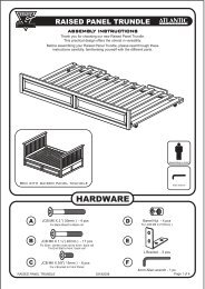
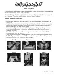
7.2 Upper bearing adjustments:<br />
The purpose of this adjustment is to centralize the blade on the gear and avoid it<br />
falling down.<br />
First of all disconnect the machine from the electricity supply. Then loosen blade<br />
No.06(picture 01) turning handle No.01 (picture 01) counter-clockwise.<br />
Take out upper back lid by removing screws using the screwdriver. Loosen the<br />
three screw-nuts No.01(picture 03) using a 10mm screw-wrench.<br />
Using the screwdriver turn the screw-nut No.02 (picture 03) ¼ counter -clockwise if<br />
t h e w h e e l i s i n c l i n e d t o w a r d s t h e f r o n t o r t u r n i t ¼<br />
clockwise if it is inclined backwards. Tighten the three screw-nut No.01(picture 03)<br />
previously loosen. Calibrate the blade according to pre-operation (5).<br />
Turn the wheels manually to check if the blade is centralized, if it is not keep turning<br />
the wheels until the blade is centralized.<br />
Picture - 03<br />
01<br />
02 03<br />
7.3 Cutting Regulator:<br />
The cutting regulator No.12 (picture 01) (optional) was designed to provide cuts<br />
with the same thickness and also to protect the operator from getting injured.<br />
To adjust the cutting regulator proceed as follows:<br />
Turn locking knob No.15 (picture 01) counter-clockwise to be able to move the<br />
cutting regulator to the left and right according to the distance you want to leave from it to the<br />
blade.<br />
Then turn the locking knob No.15 (picture 01) clockwise to fix the cutting regulator<br />
in the desired position.<br />
7<br />
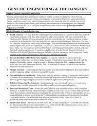
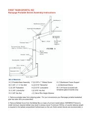
OBSERVACIÓN<br />
Al hacer el ajuste de las correas , verifique también el alineamiento de las poleas .<br />
Con un destornillador , saque los tornillos que fijan la tapa trasera inferior y retírela<br />
, <strong>para</strong> tener acceso a las poleas . Usando una llave de tuerca ( 9/16" ) No. 02 (Foto 05) afloje los<br />
tornillos No.01 (Foto 05 ) girándolos en sentido anti-horario . En seguida con el auxilio de una<br />
palanca de madera No.03 (Foto 05) , empuje el motor en el sentido que provoque una mayor tensión<br />
de las Correas No. 05 (Foto 05) , después apriete los tornillos No.01 (Foto 05) .<br />
FOTO - 02<br />
Foto - 06<br />
03 04 05<br />
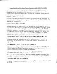
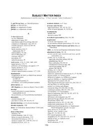
5.2.2 Ajuste del Cojinete Superior No.03 (Foto 06):<br />
El propósito de este ajuste es centralizar la hoja en el volante y evitar que la misma<br />
salte afuera de el.<br />
Primero desconecte la maquina de la red eléctrica. Después afloje la hoja No.06<br />
(Foto 01) girando el manipulo No.01 (Foto 01) en el sentido anti-horario.<br />
Retire la tapa trasera superior removiendo los tornillos con un destornillador.<br />
Afloje las tres tuercas No. 01 (Foto 06) usando una llave de tuerca de 10mm.<br />
Usando un destornillador gire el tornillo superior No.02 (Foto 06) ¼ de giro en el<br />
sentido anti-horario si la lamina estuviera desplazada <strong>para</strong> adelante o gire el tornillo superior No.02<br />
(Foto 06) ¼ de giro en el sentido horario si la lamina estuviera desplazada <strong>para</strong> tras.<br />
Apriete las tres tuercas No.01 (Foto 06) previamente aflojadas.<br />
Calibre la tensión de la hoja como explicado en Pre-Operación , ítem 2.2 .<br />
Gire el volante con las manos <strong>para</strong> averiguar si la hoja esta centralizada en el<br />
volante. Si ella no está centralizada, continúe girando el volante hasta que la hoja se centralice .<br />
01<br />
01<br />
02<br />
02 03<br />
20