GEMINI GLP 35 - Trade Garage Equipment
GEMINI GLP 35 - Trade Garage Equipment
GEMINI GLP 35 - Trade Garage Equipment

You also want an ePaper? Increase the reach of your titles
YUMPU automatically turns print PDFs into web optimized ePapers that Google loves.
WorId Leader in Lift Systems<br />
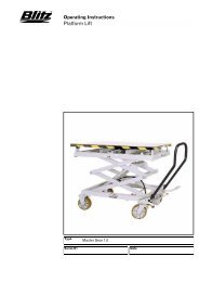
SCISSOR LIFT FREE WHEELS<br />
OPERATING INSTRUCTIONS<br />
<strong>GEMINI</strong> <strong>GLP</strong> <strong>35</strong><br />
PUENTES LEVANTACOCHES DE TIJERA<br />
CON RUEDAS LIBRES<br />
MANUAL DE INSTRUCCIONES<br />
PRODUCT SERVICE
EC DECLARATION OF<br />
CONFORMITY<br />
The Company<br />
ROTARY LIFT EUROPE S.r.l.<br />
Via Tiburtina Km 209+800<br />
65025 - MANOPPELLO SCALO - PESCARA (ITALIA)<br />
Tel. 085/8569058-Fax 085/8569059<br />
DECLARES ON ITS OWN RESPONSIBILITY THAT THE EQUIP-<br />
MENT SPECIFIED BELOW:<br />
TYPE OF EQUIPMENTS:<br />
SCISSOR LIFT FREE WHEELS<br />
MODEL: <strong>GEMINI</strong> <strong>GLP</strong> <strong>35</strong><br />
PART NUMBER: ...............................................................<br />
TO WHICH THIS DECLARATION IS RELATED, CONFORMS<br />
WITH THE FOLLOWING EUROPEAN DIRECTIVES:<br />
98/37/CE-73/23/CE-E 93/68/CE-89/336/CE<br />
IT ALSO DECLARES THAT THE FOLLOWING EUROPEAN RULES<br />
HAVE BEEN RESPECTED : EN 292.1-EN292.2- EN 294-EN 349- EN<br />
1050- PREN 811- EN 60204-1-ETS 300 683- EN 55022B- EN 1493.<br />
Name and address of the approval body:<br />
Certification number:<br />
(Place and date)<br />
. .<br />
(PRODUCTION MANAGER)<br />
YEAR OF MANUFACTURE:<br />
VOLTAGE: 220/380 Vac -220 Vac -240 Vac -110 Vac<br />
Hz: 50 Hz - 60 Hz<br />
AUTHORIZED SERVICE CENTER :<br />
WorId Leader in Lift Systems<br />
SCISSOR LIFT<br />
DECLARACIÓN DE<br />
CONFORMIDAD<br />
La empresa:<br />
ROTARY LIFT EUROPE S.r.l.<br />
Via Tiburtina Km 209+800<br />
65025 MANOPPELLO SCALO – PESCARA (ITALIA)<br />
Tel. 085/8569058-Fax 085/8569059<br />
DECLARA BAJO SU PROPIA RESPONSABILIDAD QUE EL<br />
SIGUIENTE PRODUCTO:<br />
DEFINICIÓN DEL APARATO: PUENTE LEVANTACOCHES DE<br />
TIJERA CON RUEDAS LIBRES<br />
MODELO: <strong>GEMINI</strong> <strong>GLP</strong> <strong>35</strong><br />
N° DE SERIE: ...................................................................<br />
AL CUAL SE REFIERE ESTA DECLARACIÓN ES CONFORME A<br />
LAS SIGUIENTES DIRECTIVAS EUROPEAS:<br />
98/37/CE-73/23/CE-E 93/68/CE-89/336/CE<br />
DECLARA IGUALMENTE QUE SE HAN RESPETADO LAS SIGUIEN-<br />
TES NORMAS EUROPEAS: EN 292.1-EN292.2- EN 294-EN 349- EN<br />
1050- PREN 811- EN 60204-1-ETS 300 683- EN 55022B- EN 1493..<br />
Nombre y dirección del organismo de control:<br />
Número del certificado:<br />
(Lugar y fecha)<br />
. .<br />
(EL RESPONSABLE DE PRODUCCIÓN)<br />
AÑO DE FABRICACIÓN:<br />
ALIMENTACIÓN: 220/380 Vac -220 Vac -240 Vac -110 Vac<br />
FREQUENCIA DE LA RED: 50 Hz - 60 Hz<br />
CENTRO DE ASISTENCIA AUTORIZADO:<br />
2
CONTENTS<br />
FIRST PART<br />
Chapter 1-Introduction-packing-transport. . . . . . .page 4<br />
Chapter 2-Machine description. . . . . . . . . . . . . .page 7<br />
Chapter 3-Safety. . . . . . . . . . . . . . . . . . . . . . . .page 10<br />
Chapter 4-Installation. . . . . . . . . . . . . . . . . . . . .page 13<br />
Chapter 5-Operation. . . . . . . . . . . . . . . . . . . . .page 19<br />
Chapter 6-Maintenance. . . . . . . . . . . . . . . . . . .page 20<br />
Chapter 7-Troubleshooting. . . . . . . . . . . . . . . . .page 21<br />
Chapter 8-Accessories. . . . . . . . . . . . . . . . . . . .page 25<br />
Chapter 9-Spare parts . . . . . . . . . . . . . . . . . . . .page 25<br />
SECOND PART (For the use of installer)<br />
Maintenance book. . . . . . . . . . . . . . . . . . . . . . .page 32<br />
SYMBOLS<br />
. . . . . . . . . . . . . . .HAZARD-DANGER<br />
. . . . . . . . . . . . . . . . . . . .PROHIBITED<br />
. . . . . . . . . . . . . . . . . . . . .WARNING<br />
Follow the instruction given by the messages preceded<br />
by a safety alert symbol<br />
ÍNDICE<br />
PRIMERA PARTE<br />
Cap.1- Introducción – Embalaje – Transporte. . . . .pag. 4<br />
Cap.2- Descripción del aparato. . . . . . . . . . . . . .pag. 7<br />
Cap.3- Seguridad. . . . . . . . . . . . . . . . . . . . . . .pag. 10<br />
Cap.4- Instalación. . . . . . . . . . . . . . . . . . . . . . .pag. 13<br />
Cap.5- Funcionamiento. . . . . . . . . . . . . . . . . . . .pag. 19<br />
Cap.6- Mantenimiento. . . . . . . . . . . . . . . . . . . .pag. 20<br />
Cap.7- Averías y reparaciones . . . . . . . . . . . . .pag. 21<br />
Cap.8- Accesorios. . . . . . . . . . . . . . . . . . . . . . .pag. 25<br />
Cap.9- Piezas de recambio. . . . . . . . . . . . . . . . .pag. 25<br />
SEGUNDA PARTE (Para los instaladores)<br />
Cuaderno de manutención. . . . . . . . . . . . . . . . . .pag. 32<br />
SÍMBOLOS<br />
. . . . . . . . . . . . . . . .RIESGO-PELIGRO<br />
. . . . . . . . . . . . . . . . . . .PROHIBICIÓN<br />
. . . . . . . . . . . . . . . . . . . . .ATENCIÓN<br />
Preste mucha atención a las frases precedidas<br />
por uno de estos símbolos.<br />
3
CHAPTER 1 - INTRODUCTION<br />
PACKING - TRANSPORT<br />
INTRODUCTION<br />
This manual was written for shop technicians ( car lift operators<br />
) and maintenance technicians. Before operating these<br />
car lifts, please read these instructions completely. The lift<br />
should be operated only by purposely trained technicians<br />
over 18 years of age, in full observance of the regulations in<br />
force in the country where the lift is installed. This manual<br />
covers important information for:<br />
• Safety of people;<br />
• Safety of the car lift;<br />
• Safety of lifted car.<br />
This manual is considered to be a permanent part of the lift<br />
and must be kept in an easily accessible place so that the<br />
operator can find it and refer to it any time. PARTICULARLY<br />
CAREFUL READING OF CHAPTER “3”ON SAFETY IS<br />
RECOMMENDED.<br />
All versions of “<strong>GEMINI</strong> <strong>GLP</strong> <strong>35</strong>” have been designed and<br />
built as required by:<br />
EUROPEAN RECOMMENDATIONS: EEC 98/37/CEE,<br />
73/23/CEE, 93/68/CEE, 89/336/CEE.<br />
EUROPEAN RULES: EN 291/1992, EN 292/1992, EN 294,<br />
EN349, EN1050, EN 60204-1, EN 300683, EN 55022B -<br />
EN 1493.<br />
Only skilled and previously authorized technicians should be<br />
allowed to carry out transport, assembling, setting, maintenance,<br />
overhaul, moving, dismantling operations, etc. concerning<br />
the lift. The manufacturer is not responsible for possible<br />
damage to people, vehicles and objects, caused by<br />
improper use of the lift.<br />
Read these instruction completely before operating the<br />
lift.<br />
Always start the hydraulic and electric system before the<br />
pneumatic connection from the lift to the control box is carried<br />
out.<br />
The lift must be only used for vehicles up to the specified<br />
capacity. Any inproper use of this lift is strictly forbidden<br />
Disconnect the lift from the main electric supply before<br />
any extraordinary maintenance operation.<br />
Lift installation must be carried out as specified by these<br />
instructions.<br />
Service test; proceed as described on page 33.<br />
The manufacturer is not liable for possible damage resulting<br />
from failure to follow the instruction supplied with this<br />
car lift.<br />
CAPÍTULO 1 – INTRODUCCIÓN<br />
EMBALAJE – TRANSPORTE<br />
INTRODUCCIÓN<br />
Este manual ha sido escrito para los empleados del taller que<br />
utilizan el levantacoches (operarios ) y para los técnicos que<br />
se ocupan de su mantenimiento. Es necesario leer estas<br />
instrucciones antes de realizar cualquier tipo de operación<br />
con el levantacoches. Solamente podrán realizar maniobras<br />
con el levantacoches los operarios que hayan recibido una<br />
formación adecuada al respecto y sean mayores de 18 años,<br />
siempre y cuando respeten plenamente la legislación en<br />
vigor en el país en donde se instale el levantacoches. El<br />
manual contiene información importante para:<br />
• La seguridad de las personas (que utilizan el levantacoches<br />
y se ocupan de su mantenimiento);<br />
• La seguridad del levantacoches;<br />
• La seguridad de los vehículos alzados.<br />
El manual forma parte integrante del levantacoches y debe<br />
guardarse en un lugar de fácil acceso, para que el operario<br />
lo pueda consultar rápidamente en cualquier momento.<br />
RECOMENDAMOS QUE SE LEA ATENTAMENTE EL<br />
CAPÍTULO “3”, QUE SE REFIERE A LA SEGURIDAD.<br />
Los puentes levantacoches “<strong>GEMINI</strong> <strong>GLP</strong> <strong>35</strong>” han sido<br />
diseñados y construidos respetando:<br />
Las DIRECTIVAS EUROPEAS 98/37/CE-73/23/CEE y<br />
93/68/CEE-89/336/CEE.<br />
Las NORMAS EUROPEAS EN 291.1 – EN 292.2 – EN 294<br />
– EN 349 – EN 1050 – EN 60204-1 – ETS 30 683 – EN<br />
55022B – EN 1493<br />
Solamente un técnico experto y autorizado puede llevar a<br />
cabo las operaciones de transporte, montaje, instalación,<br />
mantenimiento, revisión, desplazamiento, desmantelamiento<br />
... El fabricante no es responable de posibles daños a personas,<br />
vehículos y objetos debidos a una utilización incorrecta<br />
del levantacoches.<br />
Lea atentamente las advertencias indicadas en este<br />
manual antes de utilizar el levantacoches.<br />
LAntes de efectuar la conexión neumática del levantacoches<br />
al cuadro de control hay que poner en marcha las<br />
instalaciones eléctrica e hidraúlica.<br />
LEl levantacoches debe ser utilizado exclusivamente<br />
para alzar vehículos con la capacidad indicada. Está prohibido<br />
utilizar el levantacoches de manera indebida.<br />
LDesconecte el levantacoches de la línea de alimentación<br />
antes de realizar cualquier tipo de operación de mantenimiento.<br />
LLa instalación del levantacoches debe realizarse<br />
siguiendo las normas indicadas al respecto.<br />
Test de uso: seguir los pasos descritos en la página 33<br />
El fabricante no se responsabiliza de los posibles daños<br />
debidos al incumplimiento de las normas incluidas en este<br />
manual.<br />
4
PACKING EMBALAJE<br />
650<br />
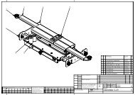
Standard versions of the car lift are pre-assembled and<br />
equipped as follows (picture 1):<br />
2 x bases and platforms (p1-p2) placed on top of each other,<br />
with pallet and wooden shims, and sealed with “pluriball”<br />
and metal clamps.<br />
1 x control box sealed with “pluriball” and metal clamps and<br />
wooden shims (packed on the lift).<br />
1 x cardboard box equipped with electric and hydraulic connections,<br />
rubber pads (packed on the lift).<br />
1 x set of short or long lifting/lowering ramps or set of spacecovering<br />
(packed on the lift).<br />
1750<br />
880<br />
pict. - fig. 1<br />
Las versiones estándard del levantacoches se envían ya montadas.<br />
La disposición del embalaje es la siguiente: (ref. fig. 1):<br />
2. bases y plataformas (P1-P2) puestas una encima de la otra<br />
con paleta y calzos de madera, selladas con pluriball y<br />
refuerzos metálicos.<br />
1. cuadro de control sellado con pluriball y refuerzos metálicos<br />
con calzos de madera (embalado sobre el puente)<br />
1. caja de cartón que contiene un kit para la conexión eléctrica<br />
e hidraúlica y almohadillas de goma (embalada sobre el<br />
puente)<br />
1. juego de rampas subida/bajada cortas o largas o juego<br />
de cubridores de espacio (embalado sobre el puente)<br />
5
TRANSPORT<br />
Packing can be lifted or moved by fork lift trucks, cranes or<br />
bridge cranes. In case of slinging, a second person must<br />
always take care of the load to avoid dangerous oscillations.<br />
At the arrival of goods, check for possible damage due to<br />
transport operations. Also verify that all items specified in the<br />
delivery notes are included. In case of damage or possible<br />
defects in transit, the person in charge or the carrier must be<br />
immediately informed. Furthermore, during loading and<br />
unloading operations goods must be handled as shown in<br />
picture 2 (when slinging, use wooden spacers to prevnt carton<br />
box from damaging).<br />
PACKING REMOVAL<br />
Wooden packing and pluriball packing can be recycled , in<br />
case of total packing removal, comply with the rules in force<br />
in the lift installation country.<br />
TRASPORTO<br />
pict. - fig. 2<br />
El embalaje puede ser alzado o desplazado con carretillas<br />
elevadoras, grúas o puentes grúa. Si hay que descargarlo<br />
con eslingado, es necesario el apoyo de otra persona para<br />
evitar posibles oscilaciones de la carga. Cuando llegue el<br />
aparato, compruebe que no haya sufrido ningún desperfecto<br />
y que estén incluidas todas las piezas indicadas en la lista<br />
del envío. Si faltan piezas, o en caso de cualquier anomalía<br />
o de que el levantacoches haya sufrido desperfectos durante<br />
el transporte, comuníqueselo inmediatamente al encargado<br />
o al transportista. Durante las operaciones de carga/descarga<br />
de la mercancía, es necesario respetar los puntos de<br />
agarre del embalaje que aparecen indicados en la figura 2<br />
(si se utilizan las cintas, hay que usar separadores de madera<br />
para evitar que se aplasten las cajas de cartón).<br />
ELIMINACIÓN DEL EMBALAJE<br />
El embalaje de madera, al igual que el pluriball, puede reciclarse.<br />
En cuanto a la eliminación del conjunto del embalaje,<br />
hay que seguir la normativa vigente en el país en el que se<br />
instale el levantacoches.<br />
6
CHAPTER 2 - MACHINE DESCRIP-<br />
TION – Models - Specifications<br />
“<strong>GEMINI</strong> <strong>GLP</strong> <strong>35</strong>” models are double-scissor and fixed (that<br />
is anchored to the ground) car lifts. They have been designed<br />
and built for vehicle lifting and placing operations.<br />
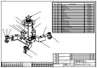
Our car lifts are equipped as folows (picture 3):<br />
A-BASE (Fixed structure)<br />
B-BOOMS, PLATFORM (Lifting and travelling structure).<br />
C-CONTROL BOX<br />
A<br />
FIXED STRUCTURE UNIT.<br />
This is the car lift base, made of a structural steel sheet with<br />
floorfixing holes.<br />
LIFTING AND TRAVELLING STRUCTURE UNIT.<br />
This is composed of steel booms and a platform. The<br />
platform is made of structural steel sheet with supporting<br />
uprights anchored to the booms by steel pins at the fixed<br />
points, and by sliders at the movable ones. Lifting system links<br />
are equipped with maintenance-free self-lubricating<br />
bushings.<br />
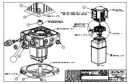
CONTROL BOX.<br />
The unit is made of a metallic box containing oil tank, pumpmotor<br />
assembly, electro-valve assembly and electrical and<br />
hydraulic supply connections. Low-voltage controls (24V) are<br />
placed on the power unit. they are the following (picture 4):<br />
B<br />
CAP. 2 - DESCRIPCIÓN DE LA MÁQUINA<br />
Modelos – Especificaciones técnicas<br />
Los puentes levantacoches de la serie “<strong>GEMINI</strong> <strong>GLP</strong> <strong>35</strong>” tienen<br />
una doble tijera y son fijos , es decir, están sujetados al suelo.<br />
Han sido diseñados y fabricados para la elevación y el estacionamiento<br />
a una cierta altura de vehículos.<br />
Nuestros levantacoches se componen de los siguientes elementos<br />
(ref. fig. 3):<br />
A- BASE ( unidad de estructura fija)<br />
B- BRAZOS – PLATAFORMA ( unidad de estructura móvil y de<br />
elevación)<br />
C- CUADRO DE CONTROL<br />
NOTE<br />
ADVERTENCIAS<br />
C<br />
SERIAL NUMBER / N° DE SERIE.<br />
pict. - fig. 3<br />
UNIDAD DE ESTRUCTURA FIJA.<br />
Está formada por la base del levantacoches, fabricada con<br />
una estructura de chapa de acero moldurado con agujeros<br />
para sujetarla al suelo.<br />
UNIDAD DE ESTRUCTURA MÓVIL Y DE ELEVACIÓN<br />
Está formada por unos brazos de acero, y por la plataforma<br />
compuesta de una chapa de acero moldurada con soportes<br />
de refuerzo sujetada a los brazos con pernos de acero en los<br />
puntos fijos, y con correderas en los móviles. Todas las articulaciones<br />
del sistema de elevación están dotadas de cojinetes<br />
autolibrificantes que no requieren ningún tipo de mantenimiento.<br />
CUADRO DE CONTROL<br />
Se compone de una caja metálica que contiene el depósito<br />
del aceite, la bomba-motor, el grupo de electroválvulas y las<br />
conexiones para las alimentaciones eléctrica e hidraúlica.<br />
Los mandos están situados en la consola, funcionan con una<br />
tensión de 24V y requieren la presencia de una persona (tipo<br />
“hombre presente”). Son los siguientes (ref. fig. 4):<br />
7
2<br />
6<br />
3<br />
1. LIFTING PUSH BUTTON<br />
2. LOWERING PUSH BUTTON<br />
3. LED<br />
4. MASTER SWITCH<br />
5. RE-ACTIVATION BUTTON<br />
6. EMERGENCY BUTTON<br />
1- Lifting push button: When pressed, motor and lifting<br />
mechanism are operated.<br />
2- Lowering push button: When pressed, lowering electrovalves<br />
are operated.<br />
3. Led: Indicates that the control board is powered.<br />
4. Master switch: The switch can be padlocked to prevent the<br />
use of the lift during the maintenance.<br />
5-Re-activation button: this button restarts the lowering button<br />
(2) for the final phase under 1,2 m.<br />
6- Emergency button: if pressed, power supply to the control<br />
unit is cut off. Turn the button clockwise (see the arrows) to<br />
restart.<br />
“<strong>GEMINI</strong> <strong>GLP</strong> <strong>35</strong>” double scissor car lifts are able to lift vehicals<br />
and vans whose weight is no more than <strong>35</strong>00 kg. All<br />
version are equipped with extension platforms so vehicals<br />
with a longer “wheel base” can be lifted. Our range of double<br />
scissor lifts can meet any demand coming from car<br />
repairmen, tyre dealers, body repairmen etc.<br />
1<br />
1. INTERRUPTOR DE SUBIDA<br />
2. INTERRUPTOR DE BAJADA<br />
3. LED<br />
4. INTERRUPTOR GENERAL<br />
5. INTERRUPTOR DE RESTABLECIMIENTO<br />
6. INTERRUPTOR DE EMERGENCIA<br />
1-Interruptor de subida; pulsándolo se ponen en marcha el motor<br />
y los mecanismos que llevan a cabo la subida del levantacoches.<br />
2-Interruptor de bajada; pulsándolo se ponen en marcha las electroválvulas<br />
que llevan a cabo la bajada del levantacoches.<br />
3-Led; indica el funcionamiento del levantacoches.<br />
4-Interruptor general; se le puede poner un candado a este interruptor<br />
para impedir su utilización durante las operaciones de<br />
reparación o mantenimiento.<br />
5- Interruptor de restablecimiento; pulsándolo se reactiva el interruptor<br />
de bajada (2) para la fase final de la bajada por debajo<br />
de los 1,2 m.<br />
6- Interruptor de emergencia; al pulsarlo se interrumpte el suministro<br />
eléctrico al cuadro de control. Para volver a ponerlo en funcionamiento,<br />
gire el interruptor en el sentido de las agujas de un<br />
reloj, como indican las flechas.<br />
pict. - fig. 5<br />
Los puentes levantacoches de doble tijera de la serie “<strong>GEMINI</strong> <strong>GLP</strong><br />
<strong>35</strong>” pueden alzar todo tipo de automóviles y furgones de un peso no<br />
superior a <strong>35</strong>00 kg. Todas las versiones disponen de prolongaciones<br />
en la plataforma para poder alzar con facilidad incluso los automóviles<br />
con una “batalla” o distancia entre las ruedas más larga.<br />
Nuestros puentes levantacoches de doble tijera pueden satisfacer las<br />
exigencias de mecánicos, vendedores de neumáticos, carroceros. al<br />
ocupar poco espacio y presentar una gran facilidad en su utilización.<br />
5<br />
4<br />
pict. - fig. 4<br />
8
OVERALL DIMENSIONS<br />
1920<br />
CHARACTERISTICS<br />
• Low-voltage controls (24V).<br />
• Hydraulic-volumetric synchronism<br />
• Hydraulic system equipped with safety mechanism in case<br />
of failure due to broken or cut tubes.<br />
• Hand lowering device in case of power failure.<br />
• Acoustic signal at the end of the lowering cycle.<br />
TECHNICAL DATA<br />
1543<br />
1543<br />
2167<br />
480<br />
125/1<strong>35</strong><br />
970<br />
WARNING: “<strong>GEMINI</strong> <strong>GLP</strong> <strong>35</strong>” low-profile car lift has<br />
been designed and built to lift and place car at heights in closed<br />
areas (special applications upon request). Any other use is forbidden,<br />
and particularly, the following operations cannot be<br />
performed:<br />
- VARNISHING, - LIFTING OF PEOPLE OR SCAFFOLDING,<br />
- SQUASHING PRESS, - CAR JACK OR WHEEL REPLACEMENT.<br />
<strong>GEMINI</strong> <strong>GLP</strong> 30<br />
• Operation . . . . . . . . . . . .Electro-hydraulic.<br />
• Capacity . . . . . . . . . . . . .<strong>35</strong>00 kg.<br />
• Weight . . . . . . . . . . . . . .From - to - kg.<br />
• Lifting time . . . . . . . . . . . .50 sec.<br />
• Lowering time . . . . . . . . .50 sec.<br />
• Motor . . . . . . . . . . . . . .3ph 3kw 220/380V 50Hz.<br />
• Noise level . . . . . . . . . . .
CHAPTER 3 - SAFETY CAP. 3 - SEGURIDAD<br />
GENERAL RULES<br />
Read this chapter carefully it contains important information<br />
concerning the safety of the operator. The operator and the<br />
maintenance personnel are required to observe the accident<br />
prevention legislation in force in the country of installation of<br />
the lift.<br />
DANGER AREA<br />
ZONA DE RIESGO<br />
OPERATOR AREA<br />
ZONA DEL OPERARIO<br />
1 During lifting or lowering operations, the lift<br />
must be operated only from the operator area as<br />
shown in the diagram (picture 7).<br />
2 Standing or passing within the danger area<br />
when the lift is working or the vehicle is raised is<br />
strictly forbidden.<br />
3 The operator must make sure the hazard area is<br />
clear when lifting or lowering the lift<br />
4 Never use the lift without protection or when<br />
safety devices are off-line.<br />
5 Always use the rubber pads when lifting a vehicle,<br />
observing the proper points of support specified<br />
by the vehicle’s manufacturer.<br />
6 Switch off the engine and engage the parking<br />
brake after placing the vehicle on the car lift;<br />
Furthermore, disengage the shift lever and move it<br />
to the “neutral position.<br />
7 To prevent the vehicle from falling make sure it<br />
is properly placed on the lift.<br />
8 Getting in or on the vehicle and-or starting the<br />
engine when the car lift is raised is strictly forbidden.<br />
9 Never leave objects and-or obstructions under<br />
the vehicle or scattered on it during the lowering<br />
phase.<br />
10 Keep the area under/next to the lift clear and<br />
NORMAS GENERALES DE PRECAUCIÓN<br />
Es muy importante leer este capítulo en su totalidad con atención<br />
ya que contiene información importante sobre los riesgos<br />
que puede correr el operario en caso de utilización<br />
incorrecta del levantacoches. El operario debe respetar las<br />
prescipciones recogidas en la legislación sobre prevención<br />
de accidentes laborales vigente en el país en el que se instala<br />
el levantacoches.<br />
pict. - fig. 7<br />
1. Durante las operaciones de subida y bajada del<br />
levantacoches, es importante que el operario actúe<br />
solamente en su zona de control, tal y como aparece<br />
indicado en la figura 7.<br />
2. Está prohibido detenerse o transitar por la zona de<br />
riesgo mientras el levantacoches está en funcionamiento,<br />
y también cuando el vehículo ha sido alzado.<br />
3. Durante las operaciones de subida y bajada del<br />
levantacoches, el operario tiene la obligación de asegurarse<br />
de que la zona de riesgo está despejada.<br />
4. No utilice nunca el aparato sin protección ni con los<br />
dispositivos de seguridad desactivados ni forzados.<br />
5. Para alzar un vehículo, utilice las almohadillas de<br />
goma suministradas con el aparato respetando los puntos<br />
de apoyo indicados por el fabricante del automóvil.<br />
6. Una vez que el automóvil se encuentra situado en el<br />
levantacoches, apague el motor y ponga el freno de<br />
mano. Además, acuérdese de situar la palanca de cambio<br />
en “punto muerto”.<br />
7. Para evitar el riesgo de que el automóvil se caiga,<br />
asegúrese de que está situado de manera correcta en el<br />
levantacoches.<br />
8. Está terminantemente prohibido subir al automóvil<br />
y/o ponerlo en marcha con el levantacoches alzado.<br />
9. Está prohibido dejar objetos debajo del vehículo o<br />
desparramados durante la fase de bajada del levantacoches.<br />
10
emove possible oil spots to avoid the risk of slipping.<br />
11 Never use water-steam-varnish-solvent jets in<br />
the lift area, and particularly, close to the control<br />
box.<br />
12 Proper lighting is extremely important. Make<br />
sure all areas next to the car lift are well and<br />
uniformly lie, according to that specified by the<br />
applicable laws of the place of installation.<br />
13 Climbing on the platform when lifting the vehicle<br />
or when the same has been already raised is<br />
strictly forbidden.<br />
14 Any use of the lift other than what herein specified<br />
can cause serious accidents to the operator<br />
as well as to the people in close proximity.<br />
15 The tampering of safety devices is strictly forbidden.<br />
16 Never exceed the maximum lifting capacity.<br />
Make sure the vehicles to be raised are without<br />
loads.<br />
17 In case of anomaly, stop the car lift and block<br />
the on/off selector by using a padlock. Only skilled<br />
technicians should be allowed to restart the lift.<br />
Be sure the power supply is off before repairing<br />
and servicing the lift. The operator, the lift or the<br />
vehicles raised can be seriously damaged if these<br />
instruction are not followed.<br />
SAFETY DEVICES<br />
ANTI-SHEARING SAFETY. The lift is equipped with a device<br />
that stops its lowering phase at 1,2m. from the floor. To<br />
restart and close the lift, release the lowering button (2) (see<br />
pict.4), press and release the yellow re-activation button (5)<br />
(see pict.4), and press the lowering button again. During the<br />
lowering phase, the device will produce a warning acoustic<br />
signal (beep).<br />
SAFETY VALVE FOR AUTOMATIC LOWERING CUT OUT.<br />
Parachute valves able to automatically lock a single or double-acting<br />
cylinder in case a sudden increase in velocity<br />
occurs. The valves are located inside the cilynders and prevent<br />
the load from falling down in case of sudden pipe bursting<br />
or cutting.<br />
DEAD-MAN CONTROL. The car lift is equipped with a deadman<br />
control. Lowering and lifting operations are stopped<br />
immediately by releasing push button controls.<br />
DOUBLE-CIRCUIT HYDRAULIC SAFETY. The lift is equipped<br />
with a double hydraulic system working idependently. Each<br />
separate circuit is able to support the rated charge but is not<br />
able to lift the charge. This is to guarantee that all placing<br />
(servicing) and lowering operations can be performed even<br />
in case of a faulty line, whereas lifting operations are not<br />
possible.<br />
10. Mantenga limpia la zona en torno al levantacoches<br />
limpiando las manchas de aceite para evitar el peligro<br />
de resbalones.<br />
11. Está prohibido utilizar chorros de agua-vapor-pintura-disolventes<br />
en las zonas en torno al levantacoches<br />
y al cuadro de control.<br />
12. Es un riesgo no disponer de una iluminación adecuada.<br />
Por lo tanto, compruebe que todas las zonas<br />
estén iluminadas de manera uniforme.<br />
13. Está terminantemente prohibida la presencia de<br />
personas y que éstas “trepen” por las plataformas tanto<br />
durante la fase de subida como una vez que el vehículo<br />
ya ha sido alzado.<br />
14. Se prohibe todo uso de levantacoches que no fuere<br />
aquel para el cual ha sido diseñado. Si no se respeta<br />
esta norma se pueden provocar accidentes graves para<br />
personas y objetos.<br />
15. Queda terminantemente prohibida la manipulación<br />
de los dispositivos de seguridad.<br />
16. Se prohibe terminantemente superar la capacidad<br />
máxima de elevación del aparato. Por lo tanto, asegúrese<br />
de que los vehículos no estén cargados.<br />
17. En caso de funcionamiento anómalo del levantacoches,<br />
párelo y cierre el seleccionador on /off bloqueándolo<br />
con un candado. Sólo el personal especializado<br />
podrá restablecer su funcionamiento. Antes de<br />
realizar la reparación y el mantenimiento del levantacoches,<br />
asegúrese de que la corriente eléctrica haya<br />
sido desconectada de la red principal.<br />
DISPOSITIVOS DE SEGURIDAD<br />
DISPOSITIVO ANTICIZALLAMIENTO. El levantacoches<br />
dispone de un dispositivo que, durante la fase de bajada,<br />
para el puente a 1,2 m. del suelo. Para volver a ponerlo en<br />
marcha y cerrar el puente, hay que soltar el interruptor de<br />
bajada (2) (ref. fig. 4), pulsar y soltar el interruptor de reactivación<br />
amarillo (5) (ref. fig. 4) y pulsar de nuevo el interruptor<br />
de bajada (2) (ref. fig. 4). En la fase de cierre, el<br />
dispositivo emitirá una señal acústica de advertencia (bip)<br />
durante toda la fase de bajada.<br />
VÁLVULA DE SEGURIDAD PARA EL BLOQUEO<br />
AUTOMÁTICO DE LA BAJADA.<br />
El dispositivo de seguridad está compuesto de unas válvulas<br />
(paracaídas) que bloquean automáticamente los cilindros si<br />
la velocidad de bajada aumenta de manera incontrolable.<br />
Dichas válvulas están situadas en el interior de los cilindros e<br />
impiden la caída de la carga en caso de explosión o corte<br />
accidental de los conductos hidraúlicos.<br />
SISTEMA DE “HOMBRE PRESENTE”. El levantacoches dispone<br />
de un sistema de operación que requiere la presencia del<br />
operario (“HOMBRE PRESENTE”). Las operaciones de subida-bajada<br />
(así como todas las demás operaciones) se interrumpen<br />
inmediatamente cuando se sueltan los pulsadores del<br />
cuadro.<br />
11
MASTER SWITCH. The master switch (4) (pict. 4). It desactivates<br />
all functions. Padlock the switch to prevent unauthorized<br />
personnel from using the lift.<br />
EMERGENCY STOP. By pressing the mushroom button (6)<br />
(see pict.4), power supply to the lift is cut off and all functions<br />
are disconnected.<br />
DISPOSITIVO DE SEGURIDAD HIDRAÚLICO CON DOBLE<br />
CIRCUITO. El puente está dotado de un doble sistema<br />
hidraúlico independiente. Cada circuito tiene la capacidad<br />
de sostener la carga nominal, pero no tiene la capacidad de<br />
alzar la carga. Esto garantiza que si se avería una línea, el<br />
puente puede efectuar de todas maneras las operaciones de<br />
estacionamiento a una cierta altura (para trabajar) y la de<br />
bajada del vehículo, pero no puede alzarlo.<br />
INTERRUPTOR GENERAL. El interruptor general (4) (ref. fig. 4),<br />
que desactiva todas las funciones del puente. Poner un candado<br />
en el interruptor para evitar que lo usen personas ajenas<br />
a la empresa.<br />
PARADA DE EMERGENCIA. Se pone en marcha pulsando<br />
del interruptor durante algún tiempo (6) (ref. fig. 4). Así se<br />
desactiva el suministro eléctrico del puente, y con ello todas<br />
sus funciones.<br />
12
CHAPTER 4 - INSTALLATION CAP. 4 - INSTALACIÓN<br />
UNPACK THE GOODS AND CHECK FOR POSSIBLE<br />
DAMAGE BEFORE INSTALLING THE LIFT.<br />
ONLY SKILLED TECHNICIANS, APPOINTED BY THE<br />
MANUFACTURER, OR BY AUTHORIZED DEALERS<br />
SHOULD BE ALLOWED TO INSTALL THE CAR LIFT.<br />
SERIOUS DAMAGE TO PEOPLE OR EQUIPMENT CAN<br />
BE CAUSED IF THIS RULE IS NOT FOLLOWED.<br />
The lift must be installed according to the specified safe<br />
distance from walls, columns, other equipments etc. The room<br />
must be a minimum 4500 mm. in height. The minimum<br />
distance from walls must be 1500 mm. take into consideration<br />
the necessary space to work easily. Further space for the<br />
control site and for possible runways in case of emergency is<br />
also necessary. (picture 8).<br />
INSTALLATION PROCEDURE<br />
1. Lift location.<br />
2. Check for power supply availability.<br />
3. Hydraulic connections.<br />
4. Electric network connection.<br />
5. Concrete base and fixing of the lift.<br />
6. Initial running.<br />
1) LOCATION OF THE LIFT<br />
P2 P1<br />
min.<br />
1500<br />
h 4500 min.<br />
max<br />
2000<br />
min.<br />
800<br />
70 cm<br />
TO OPEN<br />
PARA ABRIR<br />
Place the automotive lift using a crane truck or any other lifting<br />
equipment in the desired position. Raise (to open the lift)<br />
the two platforms using a crane, following the intructions in<br />
the picture, and place them at a height of about 70 cm.<br />
Insert a wooden shim to prevent the lift from closing during<br />
the slinging phase. To move the car lift, sling it as described<br />
in picture 8 and place it into the right position. Use metal<br />
shims to level the ground where necessary.<br />
ANTES DE LLEVAR A CABO LA INSTALACIÓN DEL<br />
LEVANTACOCHES, RETIRE EL EMBALAJE Y REVISE LA<br />
MERCANCÍA.<br />
LA INSTALACIÓN DEL LEVANTACOCHES ES COMPE-<br />
TENCIA DE TÉCNICOS ESPECIALIZADOS, DESIGNA-<br />
DOS POR EL FABRICANTE O POR VENDEDORES<br />
AUTORIZADOS. SI NO SE RESPETA ESTA NORMA, SE<br />
PUEDEN CAUSAR SERIOS DAÑOS A PERSONAS Y A<br />
OBJETOS.<br />
Hay que instalar el levantacoches respetando las distancias<br />
de seguridad respecto a paredes, columnas, otros aparatos...<br />
La altura mínima del local debe ser de 4500 mm.<br />
Tomando en cuenta el espacio necesario para trabajar con<br />
comodidad, el cuadro de control y las salidas en caso de<br />
emergencia, la distancia mínima a las paredes debe ser por<br />
lo menos de 1500 mm.(ref. fig. 8)<br />
PROCEDIMIENTO DE INSTALACIÓN.<br />
1) Colocar el levantacoches.<br />
2) Comprobar la disponibilidad de alimentación eléctrica.<br />
3) Conexiones hidraúlicas.<br />
4) Conexión a la red eléctrica.<br />
5) Base de cemento y sujeción del levantacoches.<br />
6) Primera puesta en marcha.<br />
1) COLOCAR EL LEVANTACOCHES.<br />
WOODEN JOIST<br />
VIGUETA DE MADERA<br />
TO MOVE<br />
PARA DESPLAZAR<br />
pict. - fig. 8<br />
Coloque el levantacoches en el punto deseado con la ayuda<br />
de un puente grúa u otro aparato de elevación adecuado.<br />
(Para abrir el levantacoches), alce con una grúa las dos plataformas<br />
siguiendo las instrucciones de la figura hasta una<br />
altura de unos 70 cm. e introduzca un calzo de madera que<br />
impida el cierre del puente cuando se vaya a alzar con una<br />
eslinga. Para desplazar el levantacoches, álcelo con una<br />
eslinga como indica la figura 8 y colóquelo en el lugar adecuado.<br />
A continuación, elimine los pequeños desniveles del<br />
suelo utilizando calzos metálicos.<br />
13
2) CHECK FOR POWER SUPPLY AVAILABILITY<br />
The room must be previously arranged for the power supply<br />
of the lift. Make sure that supplies are not far from the power<br />
unit.<br />
3) HYDRAULIC CONNECTIONS<br />
RIGHT POWER UNIT<br />
CUADRO DE CONTROL DE LA DERECHA<br />
3) CONEXIONES HIDRAÚLICAS<br />
A1 B2<br />
B1 A2 A1 B2<br />
B1 A2<br />
Pos.<br />
A<br />
B<br />
C<br />
D<br />
E<br />
F<br />
G<br />
A<br />
E<br />
G<br />
B<br />
Code<br />
04L1205<br />
04L1206<br />
04L1207<br />
04L1208<br />
04L1209<br />
04L1210<br />
04-3023<br />
F<br />
F<br />
G<br />
Description<br />
(A) PIPE R2 T 1/4 L= 4800<br />
(B) PIPE R2 T 1/4 L= 4200<br />
(C) PIPE R2 T 1/4 L= 2800<br />
(D) PIPE R2 T 1/4 L= 3150<br />
(E) PIPE R2 T 1/4 L= 680<br />
(F) PIPE R2 T 1/4 L= 2000<br />
“T” CONNECTION MMM 1/4<br />
2) COMPROBAR LA DISPONIBILIDAD<br />
DE ALIMENTACIÓN ELÉCTRICA<br />
El local debe haber sido preparado de antemano para la alimentación<br />
eléctrica del levantacoches. Asegúrese de que los<br />
enganches para dicha alimentación se encuentran listos<br />
cerca del cuadro de control.<br />
HYDRAULIC<br />
BLOCK<br />
BLOQUE<br />
F<br />
E<br />
HIDRAÚLICO<br />
D<br />
B1<br />
D<br />
E<br />
G<br />
G<br />
E<br />
F<br />
C<br />
B2<br />
A2<br />
A1<br />
C<br />
B<br />
A<br />
Pos.<br />
A<br />
B<br />
C<br />
D<br />
E<br />
F<br />
G<br />
Código<br />
04L1205<br />
04L1206<br />
04L1207<br />
04L1208<br />
04L1209<br />
04L1210<br />
04-3023<br />
LEFT POWER UNIT<br />
CUADRO DE CONTROL DE LA IZQUIERDA<br />
pict. - fig. 9<br />
Descripción<br />
TUBO (A) R2 T _ L=4800<br />
TUBO (B) R2 T 1/4 L=4200<br />
TUBO (C) R2 T _ L=2800<br />
TUBO (D) R2 T _ L=3150<br />
TUBO (E) R2 T _ L=680<br />
TUBO (F) R2 T _ L=2000<br />
EMPALME EN FORMA DE “T” MMM 1/4<br />
14
HYDRAULIC PLAN<br />
1<br />
2<br />
3<br />
4<br />
5<br />
6<br />
7<br />
OM<br />
RF<br />
M<br />
A1<br />
7 7<br />
OM-A1<br />
Suction filter<br />
6,5l. pump<br />
Oil level dipstick<br />
Full force valve<br />
Unidirectional valve<br />
Lowering electro valve (eo)<br />
Parachute valve<br />
Manual operator<br />
Flow regulator valve<br />
Three phase motor 3 KW<br />
B2 B1 A2<br />
M<br />
6<br />
A1 A2 B2 B1<br />
OM-A2 OM-B2<br />
5<br />
TANK<br />
DEPÓSITO<br />
LINEA A<br />
1<br />
LINEA B<br />
5<br />
4<br />
P T<br />
2<br />
1<br />
2<br />
3<br />
4<br />
5<br />
6<br />
7<br />
OM<br />
RF<br />
M<br />
RF<br />
6<br />
3<br />
ESQUEMA INSTALACIÓN HIDRAÚLICA<br />
HYDRAULIC BLOCK<br />
BLOQUE HIDRAÚLICO<br />
OM-B1<br />
Filtro de aspiración<br />
Bomba 6,5 litros<br />
Varilla nivel aceite<br />
Válvula de máxima<br />
Vávula unidireccional<br />
Electroválvula de bajada<br />
Válvula paracaídas<br />
Operario Manual<br />
Válvula reguladora de flujo<br />
Motor trifásico 3KW<br />
pict. - fig. 10<br />
15
4) ELECTRIC SYSTEM CONNECTION<br />
R Ø1,5<br />
S Ø1,5<br />
T Ø1,5<br />
STOP<br />
IN<br />
CM<br />
TR<br />
SR<br />
EV1<br />
EV2<br />
TM<br />
PROX1<br />
STOP<br />
24 VAC<br />
JP1<br />
IN<br />
TR<br />
0<br />
24<br />
FUSE<br />
10X38 16A<br />
Warning ! Only skilled personnel should be allowed<br />
to perform the operation shown below.<br />
Connect as follow:<br />
• Open the control box front cover and using the terminals<br />
22-25 (picture 20), connect the electric cable to the general<br />
switch cable (be sure that the cable passes trought the proper<br />
space located behind the control box). Before connecting<br />
the electric system, make sure that the power supply plant to<br />
the lift is equipped with the protection devices required by<br />
current standards in the country where the lift is installed.<br />
BE CAREFUL<br />
Before accessing inside the control box, for connection<br />
to the power or for the repair of electric equipments breakdown,<br />
make sure that the main power supply is disconnected,<br />
to avoid the possibility of electrocution.<br />
SR<br />
0<br />
220<br />
380<br />
SM<br />
JP8<br />
MAIN SWITCH<br />
4 KW 24 V DC CONTACTOR<br />
70 VA 2VCA TRANSFORMER<br />
BUZZER<br />
ELECTROVALVE<br />
ELECTROVALVE<br />
MOTOR THERMIC<br />
STOP AND GO PROXIMETRY<br />
EMERGENCY BUTTON<br />
FUSE<br />
5X20 1A<br />
CM<br />
JP10<br />
JP14<br />
A1 A1<br />
EV2<br />
+ R -<br />
STOP AND GO<br />
1<br />
BR B BL<br />
JP12<br />
CM<br />
EV1<br />
JP11<br />
JP2<br />
06L 2300 <strong>GLP</strong>30<br />
IN<br />
CM<br />
TR<br />
SR<br />
EV1<br />
EV2<br />
TM<br />
PROX1<br />
STOP<br />
4) CONEXIÓN A LA RED ELÉCTRICA<br />
M<br />
TM<br />
PROX1<br />
PROXMITY SWITCH<br />
CABLE COLORS<br />
COLORES CABLES ELÉCTRICOS<br />
BLACK / NEGRO<br />
BLEU / AZUL<br />
BROWN / MARRÓN<br />
EV 2<br />
EV 1<br />
pict. - fig. 11<br />
Atención: las operaciones indicadas a continuación pueden ser<br />
llevadas a cabo exclusivamente por parte de personal especializado.<br />
Realice la conexión al cuadro de control de la manera siguiente:<br />
• Levante la tapa del cuadro y conecte, mediante los terminales (22-<br />
25 ref. fig. 20), el cable de alimentación eléctrica al cable conectado<br />
al interruptor general, de tal manera que el cable de alimentación pase<br />
por el espacio adecuado situado en la parte posterior del cuadro.<br />
Asegúrese de que la línea de alimentación eléctrica está protegida de<br />
manera adecuada mediante un interruptor magnetotérmico con una<br />
capacidad y unas características adecuadas y conformes a la normativa<br />
de seguridad vigente.<br />
¡ATENCIÓN!<br />
Antes de intervenir en el interior del cuadro de control, para<br />
realizar la conexión a la red eléctrica o para la reparación de una<br />
avería del material eléctrico, asegúrese de que se ha desconectado<br />
el aparato de la corriente eléctrica principal, para evitar así todo riesgo<br />
de electrocución.<br />
B<br />
BL<br />
BR<br />
INTERRUPTOR GENERAL<br />
CONTACTOR 4 KW 24 V DC<br />
TRANSFORMADOR 70 VA 2VCA<br />
TIMBRE<br />
ELECTROVÁLVULA<br />
ELECTROVÁLVULA<br />
PROTECCIÓN TÉRMICA MOTOR<br />
PROXÍMETRO STOP AND GO<br />
INTERRUPTOR DE EMERGENCIA<br />
16
6) CONCRETE BASE AND FIXING OF THE LIFT<br />
114 mm. min.<br />
Drill a hole with a<br />
16mm bit.<br />
Haga un agujero con<br />
una broca de 16<br />
mm. para cemento.<br />
Clean the hole<br />
Limpie el agujero.<br />
After checking that electric and hydraulic connections are<br />
properly made (see pictures 9/10/11), make sure the two<br />
bases of the lift are levelled.<br />
The concrete floor must have a strength to 20N/mm2 min.<br />
compression and 200mm min. thickness, to have 95mm<br />
min. anchorage depth.<br />
When using the standard M10x100mm rods the<br />
floor must be perfectly levelled.<br />
Drill four 16mm dia. holes per base in the concrete floor<br />
using the base holes as a guide.<br />
•Concrete thickness required : 200mm.<br />
•Hole depth : 115mm.<br />
•Distance between holes and concrete base : 150mm.<br />
Insert the tie rod into the hole till the washer and the head<br />
of the screw contact the base. Tighten the rods to a 200Nm<br />
torque. If the rods cannot bear the specified 200Nm torque,<br />
replace the concrete under the base with a reinforced concrete<br />
block having the following specifications:<br />
•dimension: 2500mm x 2500mm 200mm (thickness).<br />
•Strength : 25Nm/mm2<br />
•lower reinforcing net : dia. 10mm / 20cm / 20cm.<br />
•upper reinforcing net : dia. 10mm /20cm / 20cm. Steel<br />
•improved adhesion steel : Fe B44K type<br />
Level the surface. Let it harden before installing the lift.<br />
6) BASE DE CEMENTO Y SUJECIÓN DEL LEVANTACOCHES<br />
Insert the tie rod into the<br />
hole till the washer and<br />
the head of the screw<br />
contact the base.<br />
Introduzca el tirante en<br />
el agujero hasta que la<br />
rondana y la parte<br />
superior del tornillo lleguen<br />
a tocar la base.<br />
114 mm.<br />
Tighten to 160/200<br />
Nm torque.<br />
15 mm.<br />
95 mm.<br />
Apriete con un par<br />
de fuerzas de<br />
160/200 Nm.<br />
pict. - fig. 12<br />
Tras realizar las conexiones eléctrica e hidraúlica (ref. fig.<br />
9/10/11), asegúrese de que dichas conexiones hayan sido realizadas<br />
de manera correcta, y de que las dos bases del levantacoches<br />
estén perfectamente paralelas.<br />
El suelo de cemento debe tener una resistencia de compresión<br />
mínima de 20N/mm2, y un espesor mínimo de 200 mm. para<br />
poder tener una profundidad de anclaje de un mínimo de 95<br />
mm. Usando los tirantes estándard M10X100 mm.<br />
el suelo debe ser totalmente horizontal. Haga 4 agujeros<br />
por cada base de 16mm. de diámetro en el suelo de cemento<br />
usando los agujeros de la base como guía.<br />
•Espesor necesario para el cemento 200 mm.<br />
•Profundidad de los agujeros 115 mm.<br />
•Distancia de los agujeros al borde del suelo de cemento 150<br />
mm.<br />
Introduzca el tirante en el agujero hasta que la rondana y la<br />
parte superior del tornillo lleguen a tocar la base. Apriete los<br />
tirantes con un par de fuerzas de 200 Nm. Si los tirantes no resisten<br />
un par de fuerzas de 200 Nm., sustituya el cemento de<br />
debajo de la base por un bloque de cemento armado de las<br />
siguientes características:<br />
•dimensiones 2500 mm X 2500 mm X 200 mm (espesor)<br />
•resistencia de 25 N/mm2.<br />
•red de armadura inferior dia. 10 mm / 20 cm X 20 cm.<br />
•red e armadura superior dia. 10 mm / 20 cm X 20 xm. de<br />
acero.<br />
•acero de adherencia mejorada del tipo Fe B44K<br />
Nivele perfectamente el suelo. Deje que se endurezca antes de<br />
instalar el levantacoches.<br />
17
7) FIRST STARTING<br />
Warning! Only skilled and authorized personnel<br />
should be allowed to perform these operations.<br />
Carefully follow all instructions shown below to prevent<br />
possible damage to the car lift or risk of injury<br />
to people.<br />
Be sure that the operating area is cleared of people.<br />
After positioning the lift as specified and performing electric<br />
and hydraulic connections, the lift can be operated by following<br />
the specific procedure.<br />
Open the front door of the control box and unscrew the oil<br />
tank cap. Using a funnel, pour 15 liters of hydraulic oil with<br />
a grade of viscosity 32 CST or equivalent. Move the master<br />
switch to the “1” position (pos. 4 pict. 4) and press the lifting<br />
button (pos. 1, pict. 4). If the lift does not operate but the<br />
motor runs regularly, check the motor for proper direction of<br />
rotation and switch the phases on the power supply line in<br />
necessary. Press the button again until platforms are fully lifted..<br />
Open the bleed screws (1) on the A2-B2 pistons (pict. 13)<br />
and close them again after bleeding air from the pistons .<br />
Open the OM A2/OM B2 manual operators half a turn (pict.<br />
10-15), press the lifting button to motor stress, then open the<br />
bleed screws again (1) (pict. 13) to bleed air from the cylinders.<br />
After tightening the bleed screws, repeat the operation<br />
to make sure there is no air in the circuit. Close the OM A2<br />
/ OM B2 manual operators, lower the lift to the round, and<br />
perform several cycles with the lift unloaded to check there<br />
are no oil leaks and plate-forms are properly levelled.<br />
Press the lowering button to lower the lift (see pict. 4 pos.2).<br />
Performs the lifting/lowering operations 4/5 times.<br />
7) PRIMERA PUESTA EN MARCHA<br />
¡Atención! Sólo un técnico cualificado y autorizado<br />
puede llevar a cabo todas estas operaciones.<br />
Siga atentamente las instrucciones para evitar que se<br />
produzcan daños a personas y al levantacoches.<br />
Asegúrese de que la zona de riesgo está despejada.<br />
Después de haber colocado el levantacoches de la manera<br />
descrita y de haber efectuado las conexiones eléctrica e<br />
hidraúlica, se puede proceder a llevar a cabo las operaciones<br />
necesarias para el funcionamiento del levantacoches.<br />
Abra la puerta anterior del cuadro de control y desenrosque<br />
el tapón del depósito de aceite. Usando un embudo, introduzca<br />
a continuación 15 litros de aceite hidraúlico con viscosidad<br />
32 CST u otro de un tipo equivalente. Ponga el interruptor<br />
general en la posición “1” (pos. 4 fig. 4), pulse el<br />
botón de subida (pos. 1 fig. 4). Si el levantacoches no se<br />
mueve pero el motor gira normalmente, asegúrese de que<br />
tenga el sentido de rotación adecuado y, si no fuera así,<br />
invierta las fases en la línea de alimentación eléctrica. Pulse<br />
de nuevo el botón hasta la subida total de las plataformas.<br />
Abra las roscas de purga (1) de los pistones A2-B2 (ref. fig.<br />
13) y ciérrelas de nuevo después de que haya salido el aire<br />
de los pistones. Abra los operarios manuales OM A2/ OM<br />
B2 una media vuelta (ref. fig. 10-15) y pulse el botón de<br />
subida hasta que fuerce el motor. Vuelva a abrir las roscas<br />
de purga (1) (ref. fig. 13) para eliminar los restos de aire de<br />
los cilindros. Tras haber cerrado de nuevo las roscas de<br />
purga, repita la operación hasta que esté seguro de que ya<br />
no queda más aire en el circuito. Cierre los operarios<br />
manuales OM A2/ OM B2, baje el levantacoches hasta el<br />
suelo y efectúe algunos ciclos sin carga para comprobar que<br />
no pierde aceite y que el puente funciona con las plataformas<br />
niveladas.<br />
Para bajar el levantacoches, pulse el botón de bajada (pos.<br />
2 fig. 4). Efectúe las operaciones de subida/bajada durante<br />
cuatro o cinco ciclos.<br />
1<br />
pict. - fig. 13<br />
18
CHAPTER 5 - OPERATION CAP. 5 - FUNCIONAMIENTO<br />
DRIVING SEQUENCE<br />
Be sure the platforms are fully closed before getting on/off<br />
the lift. Get in the vehicle and drive on the lift; be sure the<br />
vehicle is centred and both rear and front wheels are properly<br />
positioned, place the proper rubber pads on the<br />
platform (picture 14) so that they are in line with the lifting<br />
points specified by the manufacturer. Press the “lifting” button,keep<br />
it pressed until the required height is reached. To<br />
lower the lift, press the “lowering” button (picture 4, pos.2).<br />
During the lowering phase, the lift will produce a safety<br />
acoustic signal.<br />
During the first hours of operation cracking noises could<br />
occur. This is due to the natural settlement of mechanical<br />
parts and will disappear during the following hours of operation.<br />
CHECKS<br />
Perform the following checks when operating the car lift:<br />
• Carefully check the car lift and its load during<br />
lifting/lowering operation.<br />
• Check the warning acoustic signal operation of the car<br />
lift during lowering phase.<br />
• ATTENTION: When the lift is operating, there high pressure<br />
in the hydraulic pipes (270 bar max).<br />
If the plat-forms do not start simultaneously, this might be due<br />
to the following causes :<br />
air in the A2 or B2 cylinder and/or differentiated service<br />
pressure in the A2 o B2 line. In this case, repeat the previous<br />
procedure while pistons are at their max. height, operating<br />
on the two lines alternatively several times to bleed air and<br />
balance the service pressure.<br />
SECUENCIA DE FUNCIONAMIENTO<br />
pict. - fig. 14<br />
Antes de subir o bajar del levantacoches con el automóvil,<br />
asegúrese de que las plataformas estén totalmente cerradas.<br />
Suba al levantacoches con el automóvil muy lentamente,<br />
asegurándose de que éste esté bien centrado en las plataformas.<br />
Sitúe las correspondientes almohadillas de goma<br />
en la plataforma del levantacoches (ver fig.14 ) respetando<br />
los puntos de elevación aconsejados por el fabricante del<br />
automóvil. Pulse el botón de “subida” y lleve el levantacoches<br />
a la altura deseada. Para la bajada, pulse el botón de<br />
“bajada” (fig. 4 pos. 2). Durante la fase de bajada, el levantacoches<br />
emitirá una señal acústica de seguridad..<br />
Durante las primas horas de funcionamiento del levantacoches<br />
podrían oírse ruidos o chirridos debidos a que las partes<br />
mecánicas no estén todavía asentadas de manera natural.<br />
Este inconveniente desaparecerá automáticamente<br />
durante las siguientes horas de funcionamiento del aparato.<br />
CONTROLES<br />
Es necesario efectuar los siguientes controles durante el funcionamiento<br />
del levantacoches:<br />
• Durante las fases de subida/bajada, observe constantemente<br />
el levantacoches y su carga.<br />
• Compruebe el funcionamiento de la señal acústica de<br />
advertencia en la fase de bajada del levantacoches.<br />
• ATENCIÓN: Cuando en el puente hay alta presión en los<br />
tubos hidraúlicos (270 baros max).<br />
Si una de las dos plataformas sube desnivelada, podría ser<br />
debido a las siguientes causas: aire en los cilindros A2 o B2<br />
y/o presión de ejercicio diferenciada en una de las dos<br />
líneas A2 o B2. En ese caso, repita las operaciones anteriores<br />
teniendo en cuenta que la operación de purga tiene que<br />
efectuarse con los pistones a la altura máxima, e insistiendo<br />
varias veces y alternativamente en ambas líneas para poder<br />
eliminar el aire y equilibrar las presiones de ejercicio.<br />
19
CHAPTER 6 - MAINTENANCE CAP. 6 - MANTENIMIENTO<br />
WARNING! Only skilled and previously authorized personnel<br />
should be allowed to service the lift. When servicing<br />
the lift, all safety precautions must be followed to avoid accidental<br />
starting of the machine. The master switch must be<br />
padlocked in “zero” position. The key should be kept by the<br />
maintenance technician throughout the service. During service<br />
operations,all safety instructions reported in chapter,<br />
“SAFETY”, must always be followed.<br />
PERIODIC MAINTENANCE<br />
Maintenance operations must be performed at each specified<br />
maintenance period in order to keep the car lift in perfect<br />
working condition. The manufacturer is not liable for possible<br />
damage resulting from failure to follow the above instructions.<br />
• Car lift must be cleaned once a month, at least, without<br />
using chemical agents and hight pressure washing guns.<br />
Always dispose of used brake oil to prevent possible<br />
damage to the finish. Carefully check that piston rods are<br />
not damage sinced inside gaskets and seals could be<br />
seriously damaged and leakage of oil occur.<br />
• Check safety devices for proper working condition periodically.<br />
• Grease roller slideways periodically.<br />
• Check flexible tubes for proper conditions yearly.<br />
• Change oil in the hydraulic system at 5 year intervals, at<br />
least. Used oil drained from the system during oil change<br />
operations should be treated as a highly pollutant<br />
product. Always dispose of used oil as specified by the<br />
law in force in the country where the car lift is installed.<br />
• Balance the hydraulic circuit periodically. In case of<br />
leaking, proceed as follows:<br />
Raise the lift unloaded to1m height, open the OMA2 -<br />
OMB2 manual operators in a sequential order (pict. 15)<br />
and close them again to balance possible leaking<br />
between the A1 - A2 and B1 - B2 line (pict. 10)<br />
MACHINE DEMOLITION<br />
When demolishing the machine all safety precautions specified<br />
in chapter “3”-”4” must be followed. Only authorized<br />
technicians should be allowed to perform this operation.<br />
Metallic parts can be scrapped as “scrap iron”. In any case,<br />
demolished material must be eliminated according to the<br />
effective laws of the country where the car lift is installed. It<br />
must be remembered that, for fiscal purposes, any demolition<br />
operation must be properly documented as specified by the<br />
effective laws of the country where the lift is installed at the<br />
time of demolition.<br />
¡ATENCIÓN! Sólo un técnico autorizado puede llevar a cabo<br />
las tareas de mantenimiento. Durante dichas tareas, es necesario<br />
tomar todas las medidas necesarias para evitar que se ponga en<br />
funcionamiento de manera accidental. El interruptor general debe<br />
estar bloqueado en la posición “0” mediante un candado. El técnico<br />
que efectúa las tareas de mantenimiento debe estar en posesión<br />
de la llave durante toda la operación. Por supuesto, es necesario<br />
que se respeten todas las indicaciones y obligaciones indicadas en<br />
el capítulo “3” SEGURIDAD<br />
MANTENIMIENTO PERIÓDICO<br />
Para mantener el levantacoches en perfectas condiciones, hay que<br />
efectuar las operaciones de mantenimiento en los periódos indicados.<br />
Si no se respetan dichas instrucciones, el fabricante no asume<br />
ninguna responsabilidad en lo que se refiere a la garantía.<br />
• Hay que limpiar el levantacoches por lo menos una vez al mes,<br />
sin utilizar productos químicos agresivos ni pistolas de agua de<br />
alta presión. Cuidado con el aceite de los frenos, si no se elimina<br />
inmediatamente, puede estropear la pintura irreversiblemente.<br />
Es importante preservar el vástago de los pistones de<br />
posibles impurezas que podrían dañarlo, es decir, crear un<br />
desgaste prematuro o incluso una rotura de las juntas internas<br />
causando una peligrosa pérdida de aceite.<br />
• Inspeccione periódicamente el estado de los dispositivos de seguridad.<br />
• Lubrifique periódicamente con grasa el carril deslizante de los<br />
rodillos.<br />
• Inspeccione cada año el estado de los tubos flexibles de alta presión.<br />
• Cambie el aceite de la instalación hidraúlica por lo menos una<br />
vez cada 5 años. El aceite usado que se extrae de la instalación<br />
durante la operación del cambio de aceite tiene que ser tratado<br />
como un producto contaminante. Por consiguiente, habrá<br />
que eliminarlo siguiendo las prescipciones de la legislación en<br />
vigor en el país en el que se haya instalado el levantacoches.<br />
• Reequilibre periódicamente el circuito hidraúlico, tras una pérdida<br />
de aceite, de la manera siguiente: alce el puente sin carga a<br />
un metro de altura. Abra los operarios manuales OM A2/ OM<br />
B2 en este orden (ref. fig. 15) y ciérrelos a continuación. Así se<br />
reequilibran las posibles pérdidas de aceite entre las líneas A1-<br />
A2 y B1-B2 (ref. fig. 10)<br />
DEMOLICIÓN DEL APARATO<br />
Durante la demolición del aparato, hay que respetar todas las precauciones<br />
de seguridad indicadas en los capítulos “3”, “4”. Al igual<br />
que ocurre con la operación de montaje, solamente podrá efectuar<br />
la operación de demolición personal especializado. Las partes<br />
metálicas se pueden desguazar y clasificar como chatarra de hierro.<br />
En cualquier caso, todo material resultante de la operación de<br />
demolición tendrá que ser eliminado de acuerdo con la normativa<br />
vigente en el país en el que se haya instalado el levantacoches. Hay<br />
que recordar que, a efectos fiscales, es necesario documentar la<br />
demolición realizada mediante las declaraciones y documentos<br />
requeridos por la legislación vigente en el país de instalación del<br />
levantacoches.<br />
20
CHAPTER 7 - TROUBLESHOOTING<br />
Troubleshooting and possible repairs requireabsolute<br />
compliance with all safety precautions indicated in chapters<br />
3 and 6.<br />
MANUAL LOWERING<br />
OM B1<br />
LOWERING E.V.<br />
ELECT. VÁLVULA DE BAJADA<br />
OM B2<br />
OM A1<br />
If the car lift cannot perform lowering operations because of<br />
power supply interruption, faulty hydraulic valves or electric<br />
trouble in the system, the lift can be lowered manually. For<br />
manual lowering operation (emergency), perform the following:<br />
• Make sure there are no obstacles blocking the lowering<br />
phase; remember that the car lift may not be lifted again<br />
to remove possible obstacles.<br />
• Disconnect main power supply.<br />
• Loosen the manual operators (OM) (A1-B1) (see pict.15)<br />
1/2 turn.<br />
• Emergency lowering has started; speed can be increased<br />
or decreased according to the opening of screws.<br />
• Constantly check the area around the car lift, and tighten<br />
the (OM) (A1-B1) screws in case of danger or in case the<br />
lowering phase should be interrupted.<br />
• During the manual lowering phase, the presence of the<br />
operator is required in close contact with the lowering key<br />
in order to ensure immediate closing of screws and<br />
blocking of the lowering phase in case of danger (if the<br />
operator were not close to the key, his reaction would not<br />
be immediate and this might cause damage to persons<br />
and equipment).<br />
NOTE: manual lowering (emergency) operations should be<br />
performed by authorized personnel, specially trained for<br />
operating the car lift, only.<br />
CAP. 7 - AVERÍAS Y REPARACIONES<br />
Tanto la búsqueda de averías como las posibles intervenciones<br />
de reparación exigen el respeto de todas las precauciones<br />
de seguridad indicadas en el cap. “3” y en el<br />
cap. “6”.<br />
BAJADA MANUAL<br />
U-A1<br />
MAX PRESSURE VALVE<br />
VÁLVULA DE MÁXIMA<br />
U-B1<br />
OM A2<br />
U-B2<br />
U-A2<br />
pict. - fig. 15<br />
En caso de corte del suministro eléctrico o de avería de las válvulas<br />
hidraúlicas o de avería eléctrica en la instalación, si el puente no<br />
baja, se puede efectuar una operación manual para hacer que hacer<br />
que baje. Para la bajada manual (de emergencia), efectúe las<br />
siguientes operaciones:<br />
• Compruebe que no haya impedimentos u obstáculos que bloqueen<br />
la bajada; recuerde que, si los hubiera, luego ya no sería<br />
posible volver a levantar el puente para retirarlos.<br />
• Desconecte la alimentación eléctrica general.<br />
• Afloje de media vuelta los operarios manuales (OM) (A1-B1) (ref.<br />
fig. 15)<br />
• La bajada de emergencia ha empezado. La velocidad aumenta o<br />
disminuye abriendo más o menos las roscas.<br />
• Inspeccione constantemente el espacio alrededor del puente y<br />
cierre las roscas (OM) (A1-B1) si surge una situación de peligro o<br />
si se hace necesario bloquear la bajada del puente.<br />
• Para efectuar la bajada manual, es necesaria la presencia de una<br />
persona que esté en contacto con la llave que lleva a cabo la operación<br />
de bajada. Así se puede efectuar un cierre inmediato de las<br />
roscas y obtener la parada inmediata de la bajada en caso de<br />
peligro ( si la persona que efectúa la operación estuviera lejos de<br />
la llave, el tiempo necesario para la reacción y el cierre no sería<br />
inmediato y podría causar daños a personas y a objetos.)<br />
N.B. la bajada manual (de emergencia) sólo puede ser efectuada<br />
por personas autorizadas y formadas sobre el funcionamiento del<br />
puente.<br />
21
TROUBLESHOOTING<br />
SYMPTOM 1<br />
1) The lifting button is pressed, the car lift does not move<br />
and the motor does not run.<br />
POSSIBLE CAUSE 1:<br />
1A) The main switch is off.<br />
REMEDY - Check and activate.<br />
1B) Power supply is interrupted.<br />
REMEDY - Check and activate.<br />
1C) The motor contactor is faulty.<br />
REMEDY - Check the contactor coil operation and<br />
make sure it is activated when supplied with 24V.<br />
1D) Blown fuse on 24 volt power supply.<br />
REMEDY - Check the fuse on the transformer and<br />
replace it if necessary.<br />
1E) Faulty transformer.<br />
REMEDY - Check the input and output voltage of the<br />
transformer: in. 380 V, out. 24 V.<br />
1F) The motor thermic switch is activated for overheating.<br />
REMEDY - Wait for 10 minutes and try starting again;<br />
then, using a tester, make sure the contact is closed<br />
again.<br />
SYMPTOM 2<br />
2) The lifting button is pressed, the motor runs but the car<br />
lift does not move.<br />
POSSIBLE CAUSE 2:<br />
2A) Wrong rotation direction.<br />
REMEDY - Switch the phase and that the motor turns<br />
in the direction indicated by the arrow..<br />
2B) The load to lift is too heavy, the MAX PRESSURE valve<br />
(pos. 4 picture 10) is discharged.<br />
REMEDY - The lift is being used with an exceeding<br />
load, beyond the specified loading capacity.<br />
2C) The oil level in the tank is too low..<br />
REMEDY - Check the oil level by using the specific<br />
cap/dipstick and refill.<br />
2D) One or both manual operators (A1-B1) (ref. pict. 15) on<br />
the hydraulic block are open.<br />
REMEDY - Check and tighten the srews.<br />
2E) The lowering valve gaskets (OR) on the block are damaged<br />
or loose.<br />
REMEDY - Check the gaskets and replace if necessary.<br />
2F) One or both manual operators (A2-B2) (ref. pict. 15) on<br />
the hydraulic block are open.<br />
REMEDY - Check and tighten the srews.<br />
2G) Oil filter is clogged.<br />
REMEDY - Check and clean.<br />
2H) Faulty hydraulic pump.<br />
REMEDY - Check that oil comes out from one of the<br />
A1-A2 outlets on the hydraulic block after disconnecting<br />
the corresponding pipe. Replace the pump if oil does not<br />
come out from the A1-A2 outlets.<br />
2I) Blocked cylinders .<br />
REMEDY - Contact technical assistance.<br />
DIAGNOSTICA<br />
SDIAGNÓSTICO<br />
SÍNTOMA 1<br />
1) El botón de subida ha sido pulsado y el puente no se<br />
mueve. El motor no gira.<br />
CAUSA PROBABLE 1:<br />
1A) Interruptor general cerrado.<br />
SOLUCIÓN - Inspecciónelo y enciéndalo.<br />
1B) Suministro interrumpido.<br />
SOLUCIÓN - Inspecciónelo y restablezca el suministro.<br />
1C) Contactor del motor averiado.<br />
SOLUCIÓN - Compruebe que funcione la bobina del<br />
contactor y que éste se encienda cuando recibe un suministro<br />
de 24 volt.<br />
1D) Fusible fundido con el suministro de 24 volt.<br />
SOLUCIÓN - Compruébelo y, si fuera necesario, cambie<br />
el fusible del transformador.<br />
1E) Transformador averiado.<br />
SOLUCIÓN - - Compruebe que la tensión de entrada y<br />
de salida del transformador sea de en. 380 V., sal. 24 V.<br />
1F) Intervención de la protección térmica del motor por<br />
calentamiento de éste.<br />
SOLUCIÓN - Espere 10 minutos e intente volver a<br />
ponerlo en marcha. Después, compruebe con un tester<br />
que el contacto esté cerrado.<br />
SÍNTOMA 2<br />
2) El botón de subida está apretado, el motor gira pero el<br />
puente no se mueve.<br />
CAUSA PROBABLE 2:<br />
2A) Rotación del motor en sentido contrario.<br />
SOLUCIÓN - Invierta la fase y compruebe que el motor<br />
gira en el sentido indicado con la flecha.<br />
2B) La carga que tiene que levantar es demasiado pesada y<br />
la válvula de MÁX. PRESIÓN (pos. 4 fig. 10) cede.<br />
SOLUCIÓN - Se está usando el puente por encima de<br />
su capacidad de carga.<br />
2C) El nivel de aceite en el depósito es demasiado bajo.<br />
SOLUCIÓN - Inspeccione la cantidad mediante el<br />
tapón con la varilla de inspección y añada aceite.<br />
2D) Un operario manual del bloque hidraúlico, o los dos,<br />
(A1-B1) (ref. fig. 15) está abierto.<br />
SOLUCIÓN - Inspecciónelo y cierre las roscas.<br />
2E) Las guarniciones (OR) de las válvulas de bajada situadas<br />
en el bloque están deteriodadas o trefílano.<br />
SOLUCIÓN - Inspeccione las guarniciones y cámbielas<br />
si fuera necesario.<br />
2F) Un operario manual del bloque hidraúlico, o los dos,<br />
(A2-B2) (ref. fig. 15) está abierto.<br />
SOLUCIÓN - Inspecciónelo y cierre las roscas.<br />
2G) El filtro del aceite está obstruido.<br />
SOLUCIÓN - Inspecciónelo y límpielo.<br />
2H) La bomba hidraúlica está averiada.<br />
SOLUCIÓN - Compruebe que salga aceite de una de<br />
las salidas A1-A2 del bloque hidraúlico después de<br />
haber quitado el tubo correspondiente. Cambie la<br />
22
SINTOMO 3<br />
3) The lowering button is pressed but the lift does not lower.<br />
POSSIBLE CAUSE 3:<br />
3A) Make sure there are no obstacles blocking the lowering<br />
phase.<br />
REMEDY - Remove the obstacle and carefully check<br />
the area before operating the lift.<br />
3B) Make sure the main switch is on and power supply is not<br />
interrupted.<br />
REMEDY - Check and supply power to the car lift.<br />
3C) Blown fuse on the 24V power supply.<br />
REMEDY - Check and replace the fuse after eliminating<br />
the cause of the short-circuit.<br />
3D) Faulty transformer.<br />
REMEDY - Check the input and output voltage of the<br />
transformer: in. 380 V, out. 24 V.<br />
3E) Valve coils are faulty or not supplied.<br />
REMEDY - Check whether valves are activated with<br />
24V directed to the coils.<br />
3F) Damaged or faulty valves.<br />
REMEDY - Unscrew the valves on the hydraulic block<br />
one by one and make sure they move freely when supplied<br />
with 24 volt solenoids.<br />
3G) Faulty lowering block proximetry, broken cable or<br />
improperly connected to the card<br />
REMEDY - Check the proximetry and replace it if<br />
necessary.<br />
SYMPTOM 4<br />
4) The lift is closed but one of the two platforms is higher.<br />
POSSIBLE CAUSE 4:<br />
4A) Make sure there are no obstacles blocking the closing<br />
phase.<br />
REMEDY - Remove the obstacle and carefully check<br />
the area before operating the lift.<br />
4B) Platforms are not levelled.<br />
REMEDY - Should this problem occur, check the car lift<br />
first, and check for oil leaks from cylinders or pipes.<br />
To level the platforms, perform the following (ref. pict.<br />
15):<br />
• Loosen the screws (A2-B2) 1/2 turn.<br />
• Press the “Lowering ” button and wait until platforms<br />
are levelled.<br />
• If the car lift does not move, loosen the screws (A1-<br />
B1).<br />
• Tighten the screws (A2-B2) and (A1-B1) in case they<br />
were used.<br />
SYMPTOM 5<br />
5) The lift does not stop at 250 mm from the ground but<br />
keeps lowering, producing a warning signal during the<br />
lowering phase<br />
POSSIBLE CAUSE 5:<br />
5A) Faulty or improperly installed proximetry.<br />
REMEDY - Check the proximetry and replace it if<br />
necessary.<br />
bomba si no sale aceite de las salidas A1-A2.<br />
2I) Cilindros bloqueados.<br />
SOLUCIÓN - Póngase en contacto con el servicio de<br />
asistencia técnica.<br />
SÍNTOMA 3<br />
3) El botón de bajada está apretado y el puente no baja.<br />
CAUSA PROBABLE 3:<br />
3A) Compruebe que no haya obstáculos que impidan la<br />
bajada.<br />
SOLUCIÓN - Retire el obstáculo y, en cualquier caso,<br />
preste la máxima atención antes de realizar maniobras<br />
con el puente.<br />
3B) Compruebe que el interruptor general esté encendido y<br />
que la alimentación general no haya sido interrumpida.<br />
SOLUCIÓN - Inspecciónelo y, si fuera necesario, haga<br />
llegar la corriente al puente.<br />
3C) El fusible se ha fundido con una alimentación de 24 volt.<br />
SOLUCIÓN - Inspeccione y, si fuera necesario, cambie<br />
el fusible después de haber eliminado la causa del cortocircuito.<br />
3D) Transformador averiado.<br />
SOLUCIÓN - Compruebe que la tensión de entrada y<br />
de salida del transformador sea de ent. 380 V., sal. 24<br />
V.<br />
3E) Las bobinas de la válvulas son defectuosas o no reciben<br />
suministro.<br />
SOLUCIÓN - Compruebe si con 24 volt. dirigidos a las<br />
bobinas se ponen en marcha las válvulas.<br />
3F) Válvulas averiadas o defectuosas.<br />
SOLUCIÓN - Desenrosque una por una las válvulas del<br />
bloque hidraúlico y compruebe que puedan moverse<br />
cuando se les suministran 24 volt. mediante los solenoides.<br />
3G) Proxímetro de parada de la bajada averiado o cable<br />
seccionado o no conectado correctamente a la tarjeta<br />
SOLUCIÓN - Compruebe y, si fuera necesario, cambie<br />
el proxímetro.<br />
SÍNTOMA 4<br />
4) El puente está cerrado y una de las plataformas se queda<br />
más alta.<br />
CAUSA PROBABLE 4:<br />
4A) Compruebe que no haya obstáculos que bloqueen el<br />
cierre.<br />
SOLUCIÓN - Retire el obstáculo y, en cualquier caso,<br />
preste la máxima atención antes de realizar maniobras<br />
con el puente.<br />
4B) Desnivel de las plataformas.<br />
SOLUCIÓN - SSi surge este problema, inspeccione en<br />
primer lugar el levantacoches. Compruebe que no haya<br />
pérdidas de aceite de los cilindros o de los tubos.<br />
Para renivelar las plataformas, efectúe las siguientes operaciones<br />
(ref. fig. 15):<br />
• Afloje las roscas (A2-B2) de media vuelta.<br />
• Pulse el botón “Bajada” y espere a que las plataformas<br />
23
se renivelen.<br />
• Si el puente se queda parado, afloje las roscas (A1-B1)<br />
• Cierre las roscas (A2-B2) y las roscas (A1-B1) si ha<br />
sido necesario utilizarlas.<br />
SÍNTOMA 5<br />
5) El puente no se detiene a 1,2 m. del suelo sino que sigue<br />
bajando mientras que emite una señal acústica contínua<br />
durante toda la fase de la bajada.<br />
CAUSA PROBABLE 5:<br />
5A) El proxímetro de parada de la bajada no está situado<br />
correctamente o está averiado.<br />
SOLUCIÓN - Compruebe y, si fuera necesario, cambie<br />
el proxímetro.<br />
24
CHAPTER 8 - ACCESSORIES CAP. 8 - ACCESORIOS<br />
Available accessories:<br />
Set of tube extensions (2m). Rubber supports. T4B rubber pads.<br />
Standard colors: RAL 5015 - RAL 3002.<br />
Special colors and cold galvanizing are available upon request.<br />
6<br />
5<br />
4<br />
2<br />
3<br />
3<br />
2<br />
3<br />
5<br />
7<br />
Los accesorios disponibles son: un juego de tubos alargadores<br />
(2 mts.) – Soportes de goma Almohadillas de goma T4B. – Los<br />
colores de serie son: RAL 5015-RAL 3002. Si se solicita, es<br />
posible tenerlos con colores especiales y con galvanización fría.<br />
CHAPTER 9 - SPARE PARTS CAP. 9 - PIEZAS DE RECAMBIO<br />
Spare parts replacement and repair works should be performed<br />
in compliance with all safety rules indicated in chapter s<br />
3 and 6.<br />
Spare parts ordering procedure.<br />
When ordering spare parts the following must be clearly specified:<br />
• Car lift serial number and year of manufacturing .<br />
• Code of the part requested (Refer to the codes in the<br />
table).<br />
• Quantity needed.<br />
• Spare parts must be ordered directly to the manufacturer.<br />
• Specify the colour requested, (R-RED, B-BLUE, RP-RAL<br />
PARTICULAR).<br />
Spare parts must be ordered directly to the manufacturer.<br />
PICT. 16 BASE<br />
Pos. Code Description Quantity<br />
1<br />
1<br />
1<br />
2<br />
3<br />
4<br />
5<br />
6<br />
7<br />
01L2404R<br />
01L2404B<br />
01L2404RP<br />
01L2409N<br />
03-3096<br />
01L2413N<br />
01L2417N<br />
01L2221N<br />
01L2222N<br />
RED BASE<br />
BLUE BASE<br />
RAL PARTICULAR BASE<br />
RAMP, L=300mm<br />
GRUB SCREW, M6X10<br />
RAMP, L=1000mm<br />
FRONT SPACE-COVER<br />
TUBE-COVER, L=850<br />
TUBE-COVER, L=1000<br />
2<br />
2<br />
2<br />
4<br />
2<br />
4<br />
2<br />
1<br />
2<br />
La sustitución de las piezas de recambio y las intervenciones<br />
de reparación requieren que se respeten todas las precauciones<br />
de seguridad indicadas en los capítulos “3” y “6”.<br />
Procedimiento a seguir para el pedido de las piezas de<br />
recambio:<br />
Para pedir las piezas de recambio necesarias hay que:<br />
• Indicar el número de serie del levantacoches y el año de<br />
fabricación.<br />
• Indicar el código de la pieza solicitada (ver la columna<br />
“código” del cuadro).<br />
• Indicar la cantidad requerida.<br />
• Indicar el RAL requerido (R-ROJO, B-AZUL, RP-RAL ESPE-<br />
CIAL).<br />
La solicitud debe enviarse directamente al fabricante.<br />
3<br />
1<br />
1<br />
1<br />
2<br />
3<br />
4<br />
5<br />
6<br />
7<br />
3<br />
7<br />
1<br />
3<br />
01L2404R<br />
01L2404B<br />
01L2404RP<br />
01L2409N<br />
03-3096<br />
01L2413N<br />
01L2417N<br />
01L2221N<br />
01L2222N<br />
1<br />
2<br />
BASE ROJA<br />
BASE AZUL<br />
BASE RAL ESPECIAL<br />
RAMPA L=300 mm.<br />
TORNILLO PRISIONERO M6X10<br />
RAMPA L=1000 mm.<br />
CUBRIDOR DE ESPACIO ANTERIOR<br />
CUBRIDOR DE TUBO L=850 mm.<br />
CUBRIDOR DE TUBO L=1000 mm.<br />
4<br />
FIG. 16 BASE<br />
2<br />
pict. - fig. 16<br />
Pos. Código Descripción Cantidad<br />
2<br />
2<br />
2<br />
4<br />
2<br />
4<br />
2<br />
1<br />
2<br />
25
PICT. 17 BOOMS<br />
10<br />
14<br />
5<br />
12<br />
10<br />
14<br />
20<br />
4<br />
9<br />
9<br />
14<br />
5<br />
11<br />
5<br />
18<br />
5<br />
13<br />
9<br />
12<br />
Pos. Code Description Quantità<br />
1<br />
1<br />
01L2400B<br />
01L2400R<br />
BLUE LOWER INNER BOOM<br />
RED LOWER INNER BOOM<br />
24<br />
6<br />
27<br />
12<br />
9<br />
9<br />
14<br />
14<br />
14<br />
26<br />
28<br />
11<br />
7<br />
25<br />
14<br />
9<br />
16<br />
8<br />
8<br />
2<br />
2<br />
14<br />
13<br />
13<br />
23<br />
2<br />
11<br />
13<br />
1<br />
1<br />
14<br />
7<br />
9<br />
14<br />
14<br />
9<br />
28<br />
9<br />
01L2400B<br />
01L2400R<br />
23<br />
17<br />
11<br />
1<br />
15<br />
6 9<br />
3<br />
22<br />
26<br />
29<br />
<strong>35</strong><br />
25 24<br />
30<br />
9<br />
32<br />
34<br />
BRAZO INTERNO INFERIOR AZUL<br />
BRAZO INTERNO INFERIOR ROJO<br />
<strong>35</strong><br />
19<br />
27<br />
FIG. 17 BRAZOS<br />
20<br />
31<br />
21<br />
31<br />
33<br />
21<br />
pict. - fig. 17<br />
Pos. Código Descrizione Cantidad<br />
2<br />
2<br />
26
Pos. Code Description Quantity<br />
1<br />
2<br />
2<br />
2<br />
3<br />
3<br />
3<br />
4<br />
4<br />
4<br />
5<br />
6<br />
7<br />
8<br />
9<br />
10<br />
11<br />
12<br />
13<br />
14<br />
15<br />
16<br />
17<br />
18<br />
19<br />
20<br />
21<br />
22<br />
23<br />
24<br />
25<br />
26<br />
27<br />
28<br />
29<br />
30<br />
31<br />
32<br />
33<br />
34<br />
<strong>35</strong><br />
01L2400RP<br />
01L2403B<br />
01L2403R<br />
01L2403RP<br />
01L2401B<br />
01L2401R<br />
01L2401RP<br />
01L2402B<br />
01L2402R<br />
01L2402RP<br />
02L2317Z<br />
03-<strong>35</strong>24<br />
02L2306Z<br />
02L2305Z<br />
03-<strong>35</strong>26<br />
02L2301Z<br />
02L2311Z<br />
03-3120<br />
02L2312Z<br />
03-3073<br />
02L2413<br />
02L2414<br />
02L2319<br />
02L2415<br />
02L2416<br />
02L2318<br />
03-<strong>35</strong>17<br />
01L2307Z<br />
03-2998<br />
01L2406Z<br />
03-<strong>35</strong>25<br />
03-<strong>35</strong>16<br />
02L2308Z<br />
02L2307Z<br />
01L2314<br />
01L2315<br />
03-2300<br />
06-5026<br />
01L2316<br />
03-3221<br />
03-<strong>35</strong>08<br />
RAL PARTICULAR LOWER INNER BOOM<br />
BLUE LOWER OUTER BOOM<br />
RED LOWER OUTER BOOM<br />
RAL PARTICULAR LOWER OUTER BOOM<br />
BLUE UPPER OUTER BOOM<br />
RED UPPER OUTER BOOM<br />
RAL PARTICULAR UOOER OUTER BOOM<br />
BLUE UPPER INNER BOOM<br />
RED UPPER INNER BOOM<br />
RAL PARTICULAR UPPER INNER BOOM<br />
BOOM-TO-BASE/PLATFORM FIXING PIN<br />
SELF-LUBRICATING BUSHING 25X28X15<br />
LOWER CENT. PIN BUSHING<br />
LOWER BOOM CENT. JOINT PIN<br />
SELF-LOCKING NUT M20X1 H1O<br />
BOOM REAR PIN<br />
UPPER BOOM CENT. JOINT PIN<br />
SELF-LUBRICATING BUSHING 25X28X20<br />
UPPER BOOM CENT./FRONT PIN BUSHING.<br />
SELF-LUBRICATING BUSHING 30X34X20<br />
RIGHT LOWER SLIDE<br />
LEFT LOWER SLIDE<br />
UPPER BOOM LEVER PIN<br />
LEFT UPPER SLIDE<br />
RIGHT UPPER SLLIDE<br />
UPPER SLIDE COVER<br />
M5 SELF-LOCKING NUT<br />
LEVER WITH BOOMS<br />
SELF-LUBRICATING BUSHING 30X34X10<br />
MAIN LEVER<br />
SELF-LUBRICATING BUSHING 25X28X30<br />
30X34X42X26 SELF-LUBRICATING FLANGE BUSHING<br />
MAIN LEVER ROLLER<br />
ROLLER PIN<br />
CONTACT PLATE<br />
PROX-HOLDER PLATE<br />
<strong>GLP</strong>30 PROX SPRING<br />
PROXIMITY D12 NC<br />
PROX HOLDER<br />
TCIC 4,2X9,5 SELF-TAPPING SCREW<br />
TCEI M5X50 SCREW<br />
2<br />
2<br />
2<br />
2<br />
2<br />
2<br />
2<br />
2<br />
2<br />
2<br />
8<br />
4<br />
4<br />
4<br />
24<br />
4<br />
8<br />
8<br />
8<br />
22<br />
2<br />
2<br />
2<br />
2<br />
2<br />
4<br />
2<br />
2<br />
4<br />
4<br />
4<br />
4<br />
4<br />
4<br />
1<br />
1<br />
2<br />
1<br />
1<br />
2<br />
2<br />
2<br />
Pos. Código Descripción Cantidad<br />
1<br />
2<br />
2<br />
2<br />
3<br />
3<br />
3<br />
4<br />
4<br />
4<br />
5<br />
6<br />
7<br />
8<br />
9<br />
10<br />
11<br />
12<br />
13<br />
14<br />
15<br />
16<br />
17<br />
18<br />
19<br />
20<br />
21<br />
22<br />
23<br />
24<br />
25<br />
26<br />
27<br />
28<br />
29<br />
30<br />
31<br />
32<br />
33<br />
34<br />
<strong>35</strong><br />
01L2400RP<br />
01L2403B<br />
01L2403R<br />
01L2403RP<br />
01L2401B<br />
01L2401R<br />
01L2401RP<br />
01L2402B<br />
01L2402R<br />
01L2402RP<br />
02L2317Z<br />
03-<strong>35</strong>24<br />
02L2306Z<br />
02L2305Z<br />
03-<strong>35</strong>26<br />
02L2301Z<br />
02L2311Z<br />
03-3120<br />
02L2312Z<br />
03-3073<br />
02L2413<br />
02L2414<br />
02L2319<br />
02L2415<br />
02L2416<br />
02L2318<br />
03-<strong>35</strong>17<br />
01L2307Z<br />
03-2998<br />
01L2406Z<br />
03-<strong>35</strong>25<br />
03-<strong>35</strong>16<br />
02L2308Z<br />
02L2307Z<br />
01L2314<br />
01L2315<br />
03-2300<br />
06-5026<br />
01L2316<br />
03-3221<br />
03-<strong>35</strong>08<br />
BRAZO INTERNO INFERIOR RAL ESPECIAL<br />
BRAZO EXTERNO INFERIOR AZUL<br />
BRAZO EXTERNO INFERIOR ROJO<br />
BRAZO EXTERNO INFERIOR RAL ESPECIAL<br />
BRAZO EXTERNO SUPERIOR AZUL<br />
BRAZO EXTERNO SUPERIOR ROJO<br />
BRAZO EXTERNO SUPERIOR RAL ESPECIAL<br />
BRAZO INTERNO SUPERIOR AZUL<br />
BRAZO INTERNO SUPERIOR ROJO<br />
BRAZO INTERNO SUPERIOR RAL ESPECIAL<br />
PERNO ENGANCHE BRAZOS BASE/PLATAFORMAS<br />
COJINETE AUTOLUBRIFICANTE 25X28X15<br />
COJINETE PERNOS CENTRALES INFERIORES<br />
PERNO ARTICULACIÓN CENTRAL BRAZOS INFERIOR<br />
TUERCA AUTOBLOQUEANTE M 20X1 H 10<br />
PERNO POSTERIOR BRAZOS<br />
PERNO CENTRAL/ANTERIOR BRAZOS SUPERIORES<br />
COJINETE AUTOLUBRIFICANTE 25X28X20<br />
COJINETE PERNO CENTRAL/ANTERIOR BRAZOS SUPERIORES<br />
COJINETE AUTOLUBRIFICANTE 30X34X20<br />
CORREDERA INFERIOR DX<br />
CORREDERA INFERIOR SX<br />
PERNO PARA EJES BRAZO SUPERIOR<br />
CORREDERA SUPERIOR DX<br />
CORREDERA SUPERIOR SX<br />
CUBIERTAS CORREDERA SUPERIOR<br />
TUERCA AUTOBLOQUEANTE M5<br />
EJE CON BRAZOS<br />
COJINETE AUTOLUBRIFICANTE 30X34X10<br />
EJE PRINCIPAL<br />
COJINETE AUTOLUBRIFICANTE 25X28X30<br />
COJINETE AUTOLUBRIFICANTE LISTO PARA EL EMPALME 30X34X42X26<br />
RODILLO EJE PRINCIPAL<br />
PERNO PARA RODILLO<br />
PLACA DE CONTACTO<br />
PLACA PORTAPROX<br />
MUELLE PROX <strong>GLP</strong> 30<br />
PROXIMITY D12 NC<br />
SOPORTE PROX<br />
TORNILLO CON AUTOROSCA TCIC 4,2X9,5<br />
TORNILLO TCEI M5X50<br />
2<br />
2<br />
2<br />
2<br />
2<br />
2<br />
2<br />
2<br />
2<br />
2<br />
8<br />
4<br />
4<br />
4<br />
24<br />
4<br />
8<br />
8<br />
8<br />
22<br />
2<br />
2<br />
2<br />
2<br />
2<br />
4<br />
2<br />
2<br />
4<br />
4<br />
4<br />
4<br />
4<br />
4<br />
1<br />
1<br />
2<br />
1<br />
1<br />
2<br />
2<br />
2<br />
27
PICT. 18 - PISTONS<br />
9<br />
1<br />
2<br />
3<br />
4<br />
5<br />
6<br />
7<br />
8<br />
9<br />
10<br />
11<br />
3<br />
9<br />
04L1200N<br />
04L1201N<br />
01L2310Z<br />
02L2309<br />
02L2300<br />
02L2310Z<br />
04L4173<br />
04L4174<br />
03-3066<br />
03-3075<br />
04-4538<br />
5<br />
7<br />
10<br />
Pos. Code Description Quantity<br />
6<br />
P1 HYDRAULIC PISTON<br />
P2 HYDRAULIC PISTON<br />
CYLINDER CASING<br />
CYLINDER HEAD PIN<br />
CYLINDER REAR PIN<br />
PIN ROLLER WITH BOOMS<br />
P1 PISTON GASKET KIT<br />
P2 PISTON GASKET KIT<br />
TBEI SCREW M6X10<br />
30X34X25 SELF-LUBRICATING BUSHING<br />
ASAFETY VALVE<br />
11<br />
1<br />
2<br />
8<br />
9<br />
2<br />
2<br />
2<br />
2<br />
2<br />
4<br />
2<br />
2<br />
4<br />
4<br />
2<br />
3<br />
4<br />
9<br />
6<br />
1<br />
2<br />
3<br />
4<br />
5<br />
6<br />
7<br />
8<br />
9<br />
10<br />
11<br />
10<br />
5<br />
7<br />
04L1200N<br />
04L1201N<br />
01L2310Z<br />
02L2309<br />
02L2300<br />
02L2310Z<br />
04L4173<br />
04L4174<br />
03-3066<br />
03-3075<br />
04-4538<br />
10<br />
6<br />
11<br />
1<br />
CILINDRO HIDRAÚLICO P1<br />
CILINDRO HIDRAÚLICO P2<br />
CÁRTER CUBIERTA CILINDROS<br />
PERNO CULATA CILINDROS<br />
PERNO POSTERIOR CILINDROS<br />
RODILLO PERNO CON BRAZOS<br />
JUEGO JUNTAS PISTÓN P1<br />
JUEGO JUNTAS PISTÓN P2<br />
TORNILLO TBEI M6X10<br />
COJINETE AUTOLUBRIFICANTE 30X34X25<br />
VALVOLA DI SICUREZZA<br />
FIG. 18 – PISTONES<br />
2<br />
8<br />
4<br />
6<br />
10<br />
pict. - fig. 18<br />
Pos. Código Descripción Cantidad<br />
2<br />
2<br />
2<br />
2<br />
2<br />
4<br />
2<br />
2<br />
4<br />
4<br />
2<br />
28
PICT. 19 PLATFORM<br />
1<br />
1<br />
1<br />
2<br />
2<br />
2<br />
3<br />
4<br />
4<br />
4<br />
5<br />
5<br />
3<br />
01L2405R<br />
01L2405B<br />
01L2405RL<br />
01L2411R<br />
01L2411B<br />
01L2411RP<br />
02L2404Z<br />
01L2408R<br />
01L2408B<br />
01L2408RP<br />
03-3062<br />
2<br />
4<br />
Pos. Code Description Quantity<br />
RED PLATFORM<br />
BLUE PLATFORM<br />
RAL PARTICULAR PLATFORM<br />
RED LEFT EXTENSION<br />
BLUE LEFT EXTENSION<br />
RAL PARTICULAR LEFT EXRTENSION<br />
EXTENSION PIN<br />
RED RIGHT EXTENSION<br />
BLUE RIGHT EXTENSION<br />
RAL PARTICULAR RIGHT EXTENSION<br />
TCEI SCREW M6X12<br />
1<br />
5<br />
3<br />
2<br />
2<br />
2<br />
1<br />
1<br />
1<br />
2<br />
1<br />
1<br />
1<br />
2<br />
1<br />
1<br />
1<br />
2<br />
2<br />
2<br />
3<br />
4<br />
4<br />
4<br />
5<br />
01L2405R<br />
01L2405B<br />
01L2405RL<br />
01L2411R<br />
01L2411B<br />
01L2411RP<br />
02L2404Z<br />
01L2408R<br />
01L2408B<br />
01L2408RP<br />
03-3062<br />
1<br />
PLATAFORMA ROJA<br />
PLATAFORMA AZUL<br />
PLATAFORMA RAL ESPECIAL<br />
PROLONGACIÓN IZQ. ROJA<br />
PROLONGACIÓN IZQ. AZUL<br />
PROLONGACIÓN IZQ. RAL ESPECIAL<br />
PERNO PARA PROLONGACIÓN<br />
PROLONGACIÓN DCHA. ROJA<br />
PROLONGACIÓN DCHA. AZUL<br />
PROLONGACIÓN DCHA. RAL ESPECIAL<br />
TORNILLO TCEI M6X12<br />
FIG. 19 PLATAFORMA<br />
pict. - fig. 19<br />
Pos. Código Descripción Cantidad<br />
2<br />
2<br />
2<br />
1<br />
1<br />
1<br />
2<br />
1<br />
1<br />
1<br />
2<br />
29
PICT. 20 CONTROL BOX<br />
Pos. Code Description Quantity<br />
1<br />
2<br />
3<br />
3<br />
3<br />
4<br />
4<br />
4<br />
5<br />
5<br />
29<br />
10<br />
5<br />
27<br />
06-6012<br />
06-6055<br />
01-1618R<br />
01-1618B<br />
01-1618RP<br />
01-1622R<br />
01-1622B<br />
01-1622RP<br />
01-1624R<br />
01-1624B<br />
29<br />
MAIN SWITCH FINISHING<br />
LE2 4X16 A MAIN SWITCH<br />
RED CABINET<br />
BLUE CABINET<br />
RAL PARTICULAR CABINET<br />
RED DOOR<br />
BLUE DOOR<br />
RAL PARTICULAR DOOR<br />
RED CONSOLE<br />
BLUE CONSOLE<br />
4<br />
1<br />
2<br />
6<br />
3<br />
28<br />
30<br />
1<br />
1<br />
1<br />
1<br />
1<br />
1<br />
1<br />
1<br />
1<br />
1<br />
23<br />
15<br />
29<br />
12<br />
7<br />
9<br />
Pos. Código Descripción Cantidad<br />
1<br />
2<br />
3<br />
3<br />
3<br />
4<br />
4<br />
4<br />
5<br />
5<br />
8<br />
18<br />
17<br />
06-6012<br />
06-6055<br />
01-1618R<br />
01-1618B<br />
01-1618RP<br />
01-1622R<br />
01-1622B<br />
01-1622RP<br />
01-1624R<br />
01-1624B<br />
13<br />
11<br />
FIG. 20 CUADRO DE CONTROL<br />
19 1<br />
21<br />
7<br />
1<br />
16<br />
14<br />
ACABADOS PARA INTERRUPTOR GENERAL<br />
INTERRUPTOR GENERAL LE2 4X16A<br />
ARMARIO ROJO<br />
ARMARIO AZUL<br />
ARMARIO RAL ESPECIAL<br />
PUERTA ROJA<br />
PUERTA AZUL<br />
PUERTA RAL ESPECIAL<br />
CONSOLA ROJA<br />
CONSOLA AZUL<br />
11<br />
20<br />
22-25<br />
24<br />
26<br />
13<br />
pict. - fig. 20<br />
1<br />
1<br />
1<br />
1<br />
1<br />
1<br />
1<br />
1<br />
1<br />
1<br />
30
Pos. Code Description Quantity<br />
5<br />
6<br />
6<br />
6<br />
7<br />
7<br />
8<br />
8<br />
9<br />
10<br />
11<br />
12<br />
13<br />
14<br />
15<br />
15<br />
16<br />
17<br />
18<br />
19<br />
20<br />
20<br />
21<br />
22<br />
23<br />
24<br />
25<br />
26<br />
27<br />
28<br />
29<br />
30<br />
01-1624RP<br />
01-1625R<br />
01-1625B<br />
01-1625RP<br />
06-6126<br />
06-6129<br />
04-4583<br />
04-4587<br />
04-4024<br />
01-1610N<br />
04L4172<br />
01-1611<br />
04-4586<br />
04-4584<br />
02-2200<br />
02-1199<br />
04-4585<br />
04-4104<br />
04-4598<br />
06-6181<br />
06-6125<br />
06-6097<br />
06-6537<br />
06-6151<br />
06-6127<br />
06-6123<br />
06-6150<br />
06-6524<br />
06L1003<br />
06L2300<br />
06-6065<br />
04-3034<br />
RAL PARTICULAR CONSOLE<br />
CONSOLE RED COVER<br />
CONSOLE BLUE COVER<br />
CONSOLE RAL PARTICULAR COVER<br />
3KW, 4-POLE, 220-380 THREE-PHASE<br />
220V, 60HZ SINGLE-PHASE MOTOR (optional)<br />
5 AP 100 PUMP<br />
3,5 AP100 PUMP FOR SINGLE-PHASE MOTOR (optional)<br />
TANK VENT KNOB<br />
OIL TANK<br />
HYDRAULIC BLOCK <strong>GLP</strong> 30<br />
TANK COVER <strong>GLP</strong> 30<br />
PVC TUBE 3/8 L 270<br />
FLEX. TUBE R2T FG 3/8<br />
MOTOR FLANGE<br />
SINGLE-PHASE MOTOR FLANGE<br />
PVC TUBE L 170 3/8<br />
OIL INTAKE FILTER<br />
COUPLING JOINT<br />
70VA 220-380 V 24 V TRANSFORMER<br />
4KW 24VCC CONTACTOR<br />
SINGLE-PHASE MOTOR CONTACTOR<br />
10X30 20A FUSE<br />
CBD 6 TERMINAL<br />
DIN GUIDE<br />
DIN GUIDE 3X32A FUSE HOLDER<br />
TE6 GROUND TERMINAL<br />
5X20 1A GLASS FUSE<br />
TOUCHPAD<br />
ELECTRIC CARD <strong>GLP</strong> 30<br />
EMERGENCY BUTTON<br />
2mm “U” GASKET<br />
1<br />
1<br />
1<br />
1<br />
1<br />
1<br />
1<br />
1<br />
1<br />
1<br />
1<br />
1<br />
1<br />
1<br />
1<br />
1<br />
1<br />
1<br />
1<br />
1<br />
1<br />
1<br />
3<br />
3<br />
1<br />
1<br />
1<br />
1<br />
1<br />
1<br />
1<br />
0,9<br />
Pos. Código Descripción Cantidad<br />
5<br />
6<br />
6<br />
6<br />
7<br />
7<br />
8<br />
8<br />
9<br />
10<br />
11<br />
12<br />
13<br />
14<br />
15<br />
15<br />
16<br />
17<br />
18<br />
19<br />
20<br />
20<br />
21<br />
22<br />
23<br />
24<br />
25<br />
26<br />
27<br />
28<br />
29<br />
30<br />
01-1624RP<br />
01-1625R<br />
01-1625B<br />
01-1625RP<br />
06-6126<br />
06-6129<br />
04-4583<br />
04-4587<br />
04-4024<br />
01-1610N<br />
04L4172<br />
01-1611<br />
04-4586<br />
04-4584<br />
02-2200<br />
02-1199<br />
04-4585<br />
04-4104<br />
04-4598<br />
06-6181<br />
06-6125<br />
06-6097<br />
06-6537<br />
06-6151<br />
06-6127<br />
06-6123<br />
06-6150<br />
06-6524<br />
06L1003<br />
06L2300<br />
06-6065<br />
04-3034<br />
CONSOLA RAL ESPECIAL<br />
TAPA CONSOLA ROJA<br />
TAPA CONSOLA AZUL<br />
TAPA CONSOLA RAL ESPECIAL<br />
MOTOR TRIFÁSICO 3KW, 4 POLOS, 220-380<br />
MOTOR MONOFÁSICO 220V, 60 HZ (optional)<br />
BOMBA 5 L. AP 100<br />
BOMBA DE 3,5 AP 100 PARA MOTOR MONOFÁSICO (optional)<br />
TAPÓN DEPÓSITO CON VENTILACIÓN<br />
DEPÓSITO ACEITE<br />
BLOQUE HIDRAÚLICO <strong>GLP</strong> 30<br />
TAPA DEPÓSITO <strong>GLP</strong> 30<br />
TUBO PVC 3/8 L 270<br />
TUBO FLEX. R2TFG3/8<br />
BRIDA MOTOR<br />
BRIDA DE MOTOR PARA MOTOR MONOFÁSICO<br />
TUBO PVC L170 3/8<br />
FILTRO DE ASPIRACIÓN ACEITE<br />
JUNTA DE ACOPLAMIENTO<br />
TRANSFORMADOR 70VA 220-380 V 24 V<br />
CONTACTOR 4 KW 24VCC<br />
CONTACTOR PARA MOTOR MONOFÁSICO<br />
FUSIBLE 10X30 20A<br />
TERMINAL PASANTE CBD 6<br />
GUÍA DIN<br />
PORTAFUSIBLES 3X32A DE GUÍA DIN<br />
TERMINAL DE TIERRA TE6<br />
FUSIBLE DE VIDRIO 5X20 1A<br />
TECLADO<br />
TARJETA ELÉCTRICA <strong>GLP</strong> 30<br />
INTERRUPTOR DE EMERGENCIA<br />
GUARNICIÓN EN “U” DE 2 mm.<br />
1<br />
1<br />
1<br />
1<br />
1<br />
1<br />
1<br />
1<br />
1<br />
1<br />
1<br />
1<br />
1<br />
1<br />
1<br />
1<br />
1<br />
1<br />
1<br />
1<br />
1<br />
1<br />
3<br />
3<br />
1<br />
1<br />
1<br />
1<br />
1<br />
1<br />
1<br />
0,9<br />
31
MAINTENANCE BOOK CUADERNO DE MANTENIMIENTO<br />
INITIAL TEST<br />
N. DESCRIPTION TEST<br />
YES NO Notes<br />
1<br />
2<br />
3<br />
4<br />
5<br />
6<br />
7<br />
8<br />
9<br />
10<br />
NOTES:<br />
Client<br />
Floor consistency check<br />
Safety distances check (from walls, columns,<br />
ceiling, other machines etc.)<br />
Power supply line check.<br />
Lift levelling check.<br />
Lift working check.<br />
Loaded lift check.<br />
Lift fixing check.<br />
Oil level check.<br />
Hydraulic failure check.<br />
Operating instruction<br />
Stamp and signature<br />
Installer<br />
Stamp and signature<br />
Date Next test on:<br />
CONTROL INICIAL<br />
N. DESCRIPCIÓN CONTROL<br />
SÍ NO Notas<br />
1<br />
2<br />
3<br />
4<br />
5<br />
6<br />
7<br />
8<br />
9<br />
10<br />
NOTAS:<br />
Cliente<br />
Control consistencia suelo<br />
Control distancia de seguridad a paredes,<br />
columnas, techo, otras máquinas...<br />
Control línea alimentación eléctrica<br />
Control nivelación puente.<br />
Control funcionamiento levantacoches.<br />
Control levantacoches con carga.<br />
Control sujeción levantacoches.<br />
Control nivel aceite.<br />
Control posibles pérdidas circuito hidraúlico.<br />
Instrucciones de uso<br />
Sello y firma<br />
El instalador<br />
Timbro e firma<br />
Fecha Próximo control<br />
32
PERIODICAL OR OCCASIONAL VISIT<br />
N. TEST DESCRIPTION<br />
YES NO Notes<br />
1<br />
2<br />
3<br />
4<br />
5<br />
6<br />
7<br />
8<br />
NOTES:<br />
Lift maintenance and cleaning check.<br />
Oil level check.<br />
Rollers slides greasing.<br />
Movable parts greasing.<br />
High pressure flexible pipes check.<br />
Hydraulic failure check.<br />
Lift levelling check.<br />
Loaded lift check.<br />
Result of visit<br />
Client<br />
Stamp and signature<br />
Installer<br />
Stamp and signature<br />
Date Next test on<br />
Positive<br />
Negative<br />
N. DESCRIPCIÓN CONTROL<br />
SÍ NO Notas<br />
1<br />
2<br />
3<br />
4<br />
5<br />
6<br />
7<br />
8<br />
NOTAS:<br />
Control estado de mantenimiento y limpieza<br />
levantacoches<br />
Control nivel aceite<br />
Engrase vías deslizantes cilindros<br />
Engrase piezas de movimiento<br />
Control estado tubos flexibles de alta presión<br />
Control posibles pérdidas circuito hidraúlico<br />
Control nivelación levantacoches<br />
Control levantacoches con carga<br />
Resultado control:<br />
Cliente<br />
Sello y firma<br />
El instalador<br />
Sello y firma<br />
CONTROL PERIÓDICO O ESPORÁDICO<br />
Fecha Próximo control<br />
Positivo<br />
Negativo<br />
33
PERIODICAL OR OCCASIONAL VISIT<br />
N. TEST DESCRIPTION<br />
YES NO Notes<br />
1<br />
2<br />
3<br />
4<br />
5<br />
6<br />
7<br />
8<br />
NOTES:<br />
Lift maintenance and cleaning check.<br />
Oil level check.<br />
Rollers slides greasing.<br />
Movable parts greasing.<br />
High pressure flexible pipes check.<br />
Hydraulic failure check.<br />
Lift levelling check.<br />
Loaded lift check.<br />
Result of visit<br />
Client<br />
Stamp and signature<br />
Installer<br />
Stamp and signature<br />
Date Next test on<br />
Positive<br />
Negative<br />
N. DESCRIPCIÓN CONTROL<br />
SÍ NO Notas<br />
1<br />
2<br />
3<br />
4<br />
5<br />
6<br />
7<br />
8<br />
NOTAS:<br />
Control estado de mantenimiento y limpieza<br />
levantacoches<br />
Control nivel aceite<br />
Engrase vías deslizantes cilindros<br />
Engrase piezas de movimiento<br />
Control estado tubos flexibles de alta presión<br />
Control posibles pérdidas circuito hidraúlico<br />
Control nivelación levantacoches<br />
Control levantacoches con carga<br />
Resultado control:<br />
Cliente<br />
Sello y firma<br />
El instalador<br />
Sello y firma<br />
CONTROL PERIÓDICO O ESPORÁDICO<br />
Fecha Próximo control<br />
Positivo<br />
Negativo<br />
34
TESTS TO BE MADE BY THE USER<br />
TESTS DURING USE<br />
N.<br />
1<br />
2<br />
3<br />
TEST DESCRIPTION<br />
Levelling check.<br />
Hydraulic failure check.<br />
Safety devices working check.<br />
MONTHLY TESTS<br />
N.<br />
1<br />
2<br />
3<br />
TEST DESCRIPTION<br />
Lift through cleaning.<br />
Rollers slides greasing<br />
Cylinders air bleeding (if necessary).<br />
HALF-YEARLY TESTS<br />
N.<br />
1<br />
2<br />
TEST DESCRIPTION<br />
Oil level check.<br />
High pressure flexible pipes check.<br />
IN CASE OF ANOMALY, STOP THE<br />
LIFT AND CONTACT OUR SERVICE<br />
DEPARTEMENT IMMEDIATELY.<br />
N.<br />
1<br />
2<br />
4<br />
N.<br />
1<br />
2<br />
3<br />
N.<br />
1<br />
2<br />
CONTROL REALIZADO POR EL USUARIO<br />
CONTROLES REALIZADOS DURANTE EL USO DEL APARATO<br />
DESCRIPCIÓN CONTROL<br />
Control nivelación<br />
Control posibles escapes circuito hidraúlico<br />
Control funcionamiento sistemas de seguridad<br />
DESCRIPCIÓN CONTROL<br />
Limpieza general del levantacoches<br />
Engrase vías deslizantes cilindros<br />
Purga aire de los cilindros (si fuera necesario)<br />
DESCRIPCIÓN CONTROL<br />
Control nivel aceite<br />
Control estado tubos flexibles de alta presión<br />
CONTROLES MENSUALES<br />
CONTROLES SEMESTRALES<br />
EN CASO DE FUNCIONAMIENTO<br />
ANÓMALO DEL LEVANTACOCHES,<br />
PÁRELO Y PÓNGASE INMEDIATA-<br />
MENTE EN CONTACTO CON NUE-<br />
STRO SERVICIO DE ASISTENCIA.<br />
<strong>35</strong>
REPAIR<br />
Failure:<br />
Action:<br />
Date Stamp and signature<br />
REPAIR<br />
Failure:<br />
Action:<br />
Date Stamp and signature<br />
Avería:<br />
Intervención:<br />
Fecha: Sello y firma<br />
Avería:<br />
Intervención:<br />
Fecha: Sello y firma<br />
REPARACIÓN<br />
REPARACIÓN<br />
36