Download - Trade Garage Equipment
Download - Trade Garage Equipment
Download - Trade Garage Equipment
- No tags were found...

Create successful ePaper yourself
Turn your PDF publications into a flip-book with our unique Google optimized e-Paper software.
Operating InstructionsSafety1 Safety1.1 Safety Hints in these InstructionDangerDraws attention to the fact that disregardfor these instructions could leadto serious or even deadly consequences.CautionDraws attention to the fact that disregardof these instructions could undercertain circumstances lead to injuries.Indicates that disregard of these instructionscould lead to the damage ofthe machine or goods on the machine.1.2 Dangers of this machineThis machine is equipped with safety devicesand is put through safety and quality controltests but there is a threat of danger by incorrectoperation and misuse for the operator orother people in the vicinity for the machineand goods.The danger zone is contained within the outerlimits of the machine. All personnel concernedwith the• Installation• Setting Up• Operation• Maintenance• Repairof the machine must have read and fully understoodthe operating instructions.1.3 Regulatory ApplicationApplications• Lifting of weights until maximum load.• Working on the raised platform• Hand Forklifts - Transporting of loads inthe lowered position.Prohibited• Lifting and transportation of personnel• Setting up and operation of machines inthe open. Exception - machines speciallyconstructed for this purpose• Alterations and rebuilds of the machine.Positioning of the load• Load should not overhang the platform• Unintentional shifting of the load shouldbe prevented1.4 Danger through accessoriesWhen the following• Rollers• Conveyer Belts• other transport facilitiesare used the safety devices on the machinemust not be made in operational through theiruse.The danger zone is enlarged through the useof accessories1.5 EmissionsSee dimension sheet in appendix.102695 06/023
Operating InstructionsSafety1.6 Source of DangerMechanic Where? Scissors arms / underframeWhat? Crush and shearpointsDanger! Loss of limbs /lifeHydraulic Where? Hydraulic componentse.g. hosesWhat? Because of damageoil could be sprayedout under high pressureDanger! Burns and contaminationto the eyesFoot Pump Where? Operating pedals ,Lifting / LoweringWhat? Slipping off pedalCurrentDanger! Injury to the legWhere? Current carryingcomponentsWhat? TouchDanger! Life threatening1.7 Qualified OperatorsThe operator must• be over 18 years old• be instructed in the operation of the machine• have proved to the firm that he is capableof operating the machine• have read and understood the operatinginstructions• must observe the operating instructions1.8 Personal Safety <strong>Equipment</strong>For the operating of the machine:• Safety shoesFor cleaning / maintenance / repair:• Safety shoes• Work gloves• Face protectionWork on the electrical and hydrauliccomponents should only be carried outby a competent tradesman!DangerNever• remove• alter• take out of service the safety facilitiesAlways secure that the machine is outof service when• Setting up• The alteration of the employment requirements• The alteration of the operating procedure• Maintenance• Servicing• Repair1.9 Safety Measures in the WorkPlace! Secure positioning of the machine! Avoid crush and shear zones between themachine and it's surroundings! Ensure that the workplace remains cleanand clear of obstacles1.10 Conduct In An EmergencyFootpumpRelease the pump /lower pedal immediatelyE - HydraulicRelease the raise /lower push-buttonimmediatelySwitch of at themains / remove theplugSecure against furtherBy raised load support the load carryingcomponent4 102695 06/02
Operating InstructionsSafety Facilities1.11 Picture Symbols2 Safety Facilities2.1 Aperture restriction in cylinderinletRestricts the oil flow by the rupture of a hydraulichose2.2 Lowering Brake Valve (when onhand)Fig. 1: Safety and Operational hints on theLifting TruckFixed adjusted limitation of the oil flow (loweringspeed)2.3 One Way Flow Restriction Valve(when on hand)Adjustable restriction of the oil flow (loweringspeed)Attention : adjustment is dependent on load !Fig. 2:1 2 3 4 5 61. Prohibited: Carriage / Transport andLifting of personnel!2. Prohibited: Lifting and Lowering of loadson sloping surfaces!3. Prohibited: Transport with raised load!4. Accumulation of weight forbidden!5. Prohibited: Staying / Grasping under anunsecured table!6. Load must be evenly distributed (surfaceload)!2.4 Folding Screen (when on hand)Prevents grasping under the raised table.2.5 Securing Device On Wheels(transportable machines only)The securing device (brake) prevents theunintentional movement of the machine.2.6 Contact Frame (when on hand)The contact frame stops the lowering of thetable when it comes in contact with an obstacle.Raise the table with the "raise" button andremove the obstacle then complete the loweringprocess7Fig. 3: You will find the maximum permissibleload at the appendix of this instruction.102695 06/025
Operating InstructionsTaking into use3 Taking into useFor technical details see dimension sheet inappendix3.1 Setting up / AssemblyCautionWear protective gloves when assemblingthe spring.! Put the wheel brake on.! Assemble the handle and spring using thedrawing as a guide. Please use the enclosedcable binder in accordance withFig. 5.! Both ends of the shaft swivel points are tobe provided with the enclosed cover caps.HandleFig. 6:The component packet contains:• Pos. 1 - Foot pedal• Pos. 2 - Hex' bolt• Pos. 3 - Hex' nut• Pos. 4 - Bush• Pos. 5 - Spring dia ø 15x87• Pos. 6 – Breather plug R 3/8"SpringFig. 4:Fig. 7:Fig. 5:! Assemble the components in the enclosedpacket using the drawing as a guide! Exchange the tank plug for the orangebreather plugFig. 8:Have you read the operating instructionsand above all the safety pointsand above all understood them? Thenyou can take the machine into use6 102695 06/02
Operating InstructionsOperation4 Operation4.3 Shifting/TiltingFig. 9:DangerFootpedalRaiseLowerLowering- pedalFootpedal! Place yourself in front of the equipment! The locking devices of the wheels are stillon! To shift or tilt the platform place a spannerupon the top of the relevant spindle or atthe side of the frame! Now turn the spindle according to thesymbols affixed to move the platform intothe position desiredMake sure to note the load every timeyou shift the platform to prevent unwantedand dangerous changes in positionin time.• Fold foot pedal away when not in use• Wear safety shoes with none slip sole• No personnel should be within thedanger zone when raising or loweringthe table• Observe the picture symbols on the liftingmachine4.1 Lifting! Stand in front of the machine! Hold the handle firmly! Apply the wheel brakes! Fold down the foot pedal! Pump the pedal repeatedly downwardsuntil the required height is achieved! You should not travel with the machinewhen it is loaded4.2 Lowering! Stand in front of the machine! Hold the handle firmly! The wheel brakes are already applied! Hold the lowering pedal carefully downDon`t hold the lowering pedal fullydown when the table is loaded otherwisethe load will lower too quickly.102695 06/027
Operating InstructionsTaking out of use5 Taking out of use6 InspectionMachinewithfor:• maintenance• cleaning• inspection• repair• battery chargingfor:end of work6.1 Inspection before the first useThe machine is tested by the manufacturerbefore deliveryMachines that are delivered not readyfor use should be inspected by a qualifiedperson in the following aspects ;footpump12 V230 V400 V• remove load• set table ontoit’s lowest position• remove tableboardfold up the foot pedal• remove load• set table ontoit’s lowest position• remove tableboardlower machinelower machinebattery main switch into "off"position• remove load• set table ontoit’s lowest position• remove tableboardlower machineremove mains plug and ormains switch "off"• correct construction• correctness for use6.2 Regular testingRegular testing of machines at intervalsof at the longest one year shouldbe carried out by a qualified person.• use the check list on the followingpage• make a photo copy of the list• note top right on the check list• Lfd N° (check list number)• machine type• serial number• cross each point when it is in order• put the machine back into use onlywhen each point has been crossedwhen completed put the check list into theappendix of these operating instructions8 102695 06/02
Operating InstructionsInspection / Maintenance7.5 Oil Change IntervalsThe oil must be changed after the first 50working hours, thereafter at intervals of 500hours or at the latest every 2 years7.6 Checking the oil level! Sink the machine into its lowest position! Read the oil level in the oil observationbung! The level should be in the upper third ofthe bung! Top-up when necessary! Pump until oil is discharged from thebleed screws without any air bubbles! Tighten bleed screws! Check oil level and top-up if necessary! Bleed pump if necessarysee chapter 8.37.9 Control of the hydraulic hosesA yearly check on the hydraulic hosesfor a safe working condition is stipulated.The check must be carried out bya qualified tradesman.Fig. 10:Breather bungOil observationbungLowering pedalFoot pedalControl the following:• Can the following damage be observed onthe outer mantel of the hose rips, kinks,cuts, unbending, abrasions or splitting?• Are there any deformities in the hosewhen under or not under pressure?• Are there any leaks between the hoses andthe fittings? Is the hose coming out of thefitting?• When there is any damage the hoseshould be changed.• Depending on the requirements the hosesshould be changed at the latest after sixyears.7.7 Oil Change! Sink the machine into its lowest position.! Place drip tray under pump.! Remove the hydraulic hose from the pumpand place in the drip tray.! Pump the foot pedal until no more oil isdischarged from the pump.! Reconnect hose.! Remove breather bung.! Fill oil until level is in the upper third of theobservation bung.! Tank volumes:• tank 250 mm long = 1,0 l• tank 300 mm long = 1,3 l• tank 450 mm long = 1,9 l• vertical Tank = 1,2 l! replace the breather bung.7.8 Bleeding the hydraulics! Sink the machine into its lowest position.! Place drip tray under pump.! Loosen the bleed screws on the cylinders! When there are no bleed screws the cylindersare so constructed as to bleed themselves102695 06/0211
Operating InstructionsFault Finding8 Fault FindingDangerWork on the hydraulic componentsshould only be carried out by a qualifiedtradesmanObserve the safety instructionsBreather bung8.2 Machine will not raise to maximumheight! Check oil level (see 7.4)8.3 Machine does not raise with thefirst pump stroke! Depress the lowering pedal with the righthand and at the same time quickly pumpthe foot pedal with the left hand.Fig. 11:M8 grub screwLower. spindleLowering pedalFoot- pedal8.4 Pump produces no pressure! Remove the breather bung.! Lay a clean cloth (twice folded) over theopening.! Using a compressed air pistol pressurisethe tank and at the same time quicklypump the foot pedal.Fig. 12:Breather bungM8 grub screwLower. spindleLowering pedalFoot- pedal8.5 Breakdown / Maintenance ofthe valvesThe valves used normally require no maintenance.By malfunction of the pump observepositions 1-4 in the "fault finding".Should it be found that the positions 1-4 in"fault finding" produce no cure return thepump for repair.8.1 Machine lowers on its ownAdjust the lowering valve by following thisprocedure! Loosen the M8 grub screw! Leave the lowering pedal in its normalposition! Using a screwdriver slightly adjust thevalve spindle:• Anticlockwise, to raise the loweringspeed.• Clockwise, to reduce the loweringspeed and to ensure that the pumpholds the load in position.! Lightly tighten the grub screw after everyadjustment.! When adjustment is correct fully tightenthe grub screw.12 102695 06/02
Operating InstructionsGeneral9 General9.1 Transport DamageAll deliveries are to be insured by the customer.We must turn down any possibleclaims concerning transport responsibility.Our responsibility is restricted to the hand -over of the machine in brand-new condition tothe shipping agent. Should you discover anydamage to the machine, do not use it andcontact the shipping agent concerning thedamage.9.2 WarrantyEvery machine is covered by a 12 monthswarranty against material faults and incorrectassembly. The warranty covers all parts thatare returned post free within twelve monthsfor inspection. The parts will then be inspectedby us to determine whether the partswere damaged under normal use.The warranty will be declared void if the partsare found to have been overloaded, handledincorrectly or that replacement parts havebeen assembled incorrectly.9.3 Ordering of spare partsPlease give the following details when ordering;Type:Load:Year of construction:Serial Number:Part description:Order Number:10 EC Declaration of ConfomityConforming to: EC-Directives – Machines98/37/EG, appendix II AWeBLITZ M. SchneiderWerkzeug- u. MaschinenfabrikGmbHHüfinger Straße 55D-78199 Bräunlingendeclare in general responsibility, that theproductPlatform Liftconvered by this declaration confirms to theHealth and Safety rules laid down by the directivesabove.The following Norms were used for the properimplemention of the EC Directives on Healthand Safety:• DIN EN 292 1 / 2 (1994)• DIN EN 294 (1992)• DIN EN 349 (1991)• VBG 14 (1993)• DIN EN 1570 (1998)Bräunlingen, dated 01.03.2002S. Schneider, General ManagementThe address for ordering is to be found on thecover of this operating instructions.102695 06/0213
ECHR – Analysis of Statistics 2014Country-specific informationAlbaniaChart 9The Court’s caseload by stage of proceedings and decision bodyCommunicated17347%Admissible41%Single Judge orCommittee(cat. VI - VII)82%Chamber or Committee -awaiting first examination(cat. I - V)18150%Total applications366Graph 10Major procedural steps in processing applications140129Applications allocated to a judicialformation120111106Applications declared inadmissible orstruck out10080587083Applications communicated to theGovernment603948384021Applications in which judgments delivered2010 902012 2013 201414/60
Operating InstructionsAppendixDimensional Drawing102695 06/0215
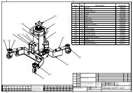
Operating InstructionsAppendixMechanical AssembliesPos. Stückzahl Benennung Best.-Nr. Bemerkung1 1 Rahmen, unten 51.02.6542 2 Bockrolle 12.09.211 ø2003 2 Lenkrolle 12.09.126 ø2004 16 6kt.-Schraube 12.51.041 M10x205 16 Scheibe 12.40.100 11 ( DIN 1441)6 16 Sicherungsmutter 12.55.065 M10 (985)7 1 Lenkbügel 51.26.0448 2 Sicherungsscheibe mitschwarzer Kunststoffkappe12.24.560 Für Ø 16 mm9 2 Zugfeder 12.23.207 3,2x20x13513 1 Schere, innen, unten 51.11.35214 1 Schere, außen, unten 51.11.35315 1 Scherenarm, oben, rechts 51.11.35116 1 Scherenarm, oben, links 51.11.35017 1 Schere, innen, oben 51.11.35418 18 Buchse 10.02.250 20x23x2019 16 Buchse 10.02.251 20x23x1520 2 Aufnahmebolzen 55.56.13621 4 Buchse 55.65.10522 8 Scheibe 12.40.090 A10,5 (9021)23 4 6kt.-Schraube 12.51.302 M10x90 (931)24 4 Sicherungsmutter 12.55.065 M10 (985)25a 4 / 2 Laufrolle, Sacklochbohrung Ø 25 10.09.679 PA 6; Ø60x48,525b 0 / 2 Laufrolle, Durchgangsbohrung Ø 25 10.28.202 PA 6; Ø60x48,526 4 Sicherungsmutter 12.55.114 M16 (985)27 2 Mittelbolzen 55.57.01628 4 Scheibe 12.40.135 A17 (9021)29 2 Gewindestift 12.54.165 AM6x16 (916)30 4 Rohe Scheibe 9 12.40.080 (1441)31 4 6kt.-Mutter 12.55.041 M8 (934)16 102695 06/02
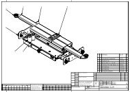
Operating InstructionsAppendixSliding and Tipping PlatformPos. Stückzahl Benennung Best.-Nr. Bemerkung1 2 Führungsrolle 10.18.214 PA 6.6 Ø 45x23 mm2 2 Führungsrolle 10.28.219 PA 6.6 Ø 42x23 mm3 2 Buchse 10.02.272 GSM 25-28-124 2 Lagerbolzen 12.16.1595 1 Spindel, Neigung 57.78.082 verzinkt5a 1 Axialrillenkugellager 10.02.031 DIN 711-511 035b 1 Stellring 12.16.612 DIN 705-A166 1 Spindel, Längsverschiebung 52.78.081 verzinkt6a 1 Axialrillenkugellager 10.02.031 DIN 711-511 016b 1 Axialrillenkugellager 10.02.031 DIN 711-511 017 1 Spindel, Querverschiebung 52.78.080 verzinkt7a 1 Axialrillenkugellager 10.02.031 DIN 711-511 017b 1 Axialrillenkugellager 10.02.031 DIN 711-511 018 1 Mittelbolzen 12.16.066 Rd. 30x43 DIN668-S235JRG2K20 4 Laufrolle mit DurchgangsbohrungØ 25 mm10.28.202 PA 6; Ø60x48,5102695 06/0217
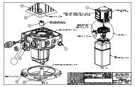
Operating InstructionsAppendixHydraulicsPos. Stückzahl Benennung Best.-Nr. Bemerkung1 2 Zylinder 11.19.071 ø40x450/6002 2 Dichtungssatz 50.97.066 ø 403 4 Buchse 10.02.264 16x18x204 4 Bolzen 55.56.132 ø16x665 2 Bolzen 55.56.1327 2 Spannhülse 12.54.1658 4 Gewindestift 12.54.165 AM6x16 (916)9 1 Hydraulikschlauch 10.19.103 1050mm lg.10 1 Hydraulikschlauch 10.19.116 400 mm lg.10a 1 L-Verschraubung 12.19.23711 2 Leitungsbruchsicherung 10.19.41512 1 Fußpumpe 12.19.358 Tank 450 mm13 2 6kt-Schraube M8x25 12.50.081 (933)14 2 Scheibe A8,4 12.40.075 (125)15 2 Sicherungsmutter M8 12.55.042 (985)18 102695 06/02
Operating InstructionsAppendixFoot pumpPos. Stückzahl Benennung Best.-Nr. Bemerkung1 1 Spiralfeder 12.17.0152 1 Sprengring 10.17.014 DIN 471 D = 20 F73 1 Bewegungsrolle 12.17.016 gehärtet4 3 Hülse 12.17.0175 1 Fußpedal 12.17.0506 2 Verbindungsstück 12.17.0187 2 6kt.-Schraube 12.51.201 M10 x 60 DIN 9318 1 Bolzen 12.17.0199 4 6kt.-Mutter 12.55.061 M10 934 8.810 2 Zugfeder 12.17.02011 1 Senkpedal 12.17.04112 1 Sprengring 10.17.040 d = 1213 1 Gewindestift 12.50.022 AM 8 x 12 DIN 91614 1 Ölschauglas und Dichtring 10.17.042 R 3/8“15 1 Entlüftungsschraube 10.28.616 R 3/8“1 Dichtungssatz 50.97.058102695 06/0219
Operating InstructionsAppendixHydraulic plan20 102695 06/02
Operating InstructionsAppendixLabelsBest.-Nr.10.33.26810.33.24110.33.24310.33.24410.33.23710.33.34210.33.34310.33.344102695 06/0221
BLITZ M. SchneiderWerkzeug- u. MaschinenfabrikGmbHHüfinger Straße 55D-78199 BräunlingenTelefon +(49) 07 71-92 33-0Telefax +(49) 07 71-92 33-99eMail info@blitz-schneider.deInternet www.blitz-schneider.de102695 06/02# Subject to change of technical data.