Untitled - Trade Garage Equipment
Untitled - Trade Garage Equipment
Untitled - Trade Garage Equipment
- No tags were found...

Create successful ePaper yourself
Turn your PDF publications into a flip-book with our unique Google optimized e-Paper software.
CONTENTSFIRST PARTChapter 1-Introduction-packing-transportChapter 2-Machine descriptionChapter 3-SafetyChapter 4-Installation.Chapter 5-OperationChapter 6-MaintenanceChapter 7-TroubleshootingChapter 8-AccessoriesChapter 9-Spare partsSECOND PART (For the use ofinstaller)Maintenance book.SYMBOLSpage 4page 7page 10page 13page 19page 20page 21page 25page 25page 32PARTE PRIMACap.1- Introduzione - Imballaggio – TrasportoCap.2- Descrizione della macchinaCap.3- SicurezzaCap.4- Installazione.Cap.5- FunzionamentoCap.6- ManutenzioneCap.7- Inconvenienti e rimediCap.8- AccessoriCap.9- Parti di ricambioPARTE SECONDA (Ad uso degliinstallatori)Libretto Metrologico.SOMMARIOpag. 4pag. 7pag. 10pag. 13pag. 19pag. 20pag. 21pag. 25pag. 25pag. 32SIMBOLOGIA. . . . . . . . . . . …….HAZARD-DANGER . . . . . . . . . . …. .. RISCHIO-PERICOLO. . . . . . . . . . . . . . . …… . .PROHIBITED . . . . . . . . . . . ………. . .. . . . . .DIVIETO. . . . . . . . . . . . . . . . . . . ... .WARNING . . . . . . .. . . . . . . . . . . …. ATTENZIONEFollow the instruction given by the messagespreceded by a safety alert symbolPrestare particolare attenzione alle frasiprecedute dagli ideogrammi.___________________________________________________________________________3
CHAPTER 1 - INTRODUCTIONPACKING - TRANSPORTINTRODUCTIONThis manual was written for shop technicians ( car liftoperators) and maintenance technicians. Before operatingthese car lifts, please read these instructions completely.The lift should be operated only by purposely trainedtechnicians over 18 years of age, in full observance of theregulations in force in the country where the lift isinstalled. This manual covers important information for:• Safety of people;• Safety of the car lift;• Safety of lifted car.This manual is considered to be a permanent part of thelift and must be kept in an easily accessible place so thatthe operator can find it and refer to it any time.PARTICULARLY CAREFUL READING OFCHAPTER “3”ON SAFETY IS RECOMMENDED.All versions of “GEMINI GLP 30” have been designedand built as required by:EUROPEAN RECOMMENDATIONS: EEC 98/37/CEE,73/23/CEE, 93/68/CEE, 89/336/CEE.EUROPEAN RULES: EN 291/1992, EN 292/1992, EN294, EN349, EN1050, EN 60204-1, EN 300683, EN55022B - EN 1493.Only skilled and previously authorized technicians shouldbe allowed to carry out transport, assembling, setting,maintenance, overhaul, moving, dismantling operations,etc. concerning the lift. The manufacturer is notresponsible for possible damage to people, vehicles andobjects, caused by improper use of the lift.Read these instruction completely before operatingthe lift.Always start the hydraulic and electric system beforethe pneumatic connection from the lift to the controlbox is carried out.The lift must be only used for vehicles up to thespecified capacity. Any improper use of this lift isstrictly forbiddenDisconnect the lift from the main electric supplybefore any extraordinary maintenance operation.Lift installation must be carried out as specified bythese instructions.Service test; proceed as described on page 33.The manufacturer is not liable for possible damageresulting from failure to follow the instructionsupplied with this car lift.CAP. 1 - INTRODUZIONEIMBALLAGGIO - TRASPORTOINTRODUZIONEQuesto manuale è stato scritto per il personale di officinaaddetto all’uso del sollevatore (operatori) e per i tecniciaddetti alla manutenzione ordinaria e straordinaria. Lalettura di questo manuale deve essere effettuata prima diqualsiasi operazione sul sollevatore. Possono manovrare ilponte sollevatore solamente operatori opportunamenteistruiti con età superiore ai 18 anni e comunque nel pienorispetto della legislazione vigente nel paese dove vieneistallato. Il manuale contiene informazioni importanti per:• La sicurezza delle persone (addette all’uso e allamanuenzione ordinaria);• La sicurezza del sollevatore;• La sicurezza dei veicoli sollevati.Il manuale è parte integrante del sollevatore e deve essereconservato in luogo facilmente accessibile, in modo chel’operatore possa consultarlo rapidamente in qualsiasimomento.SI RACCOMANDA UNA ATTENTA LETTURA DELCAPITOLO “3” RIGUARDANTE LA SICUREZZA.I ponti sollevatori “GEMINI GLP 30” sono statiprogettati e costruiti rispettando:Le DIRETTIVE EUROPEE 98/37/CE-73/23/CEE e93/68/CEE-89/336/CEE.Le NORME EUROPEE EN 291.1-EN 292.2- EN 294 –EN 349 - EN 1050 - EN 60204-1 - ETS 30 683 - EN55022B - EN 1493.Tutte le operazioni sul sollevatore, trasporto, montaggio,installazione, manutenzione, revisione, spostamento,smantellamento ecc. devono essere eseguite da personaleesperto e preventivamente autorizzato. Il costruttore nonrisponde di alcun danno a persone, veicoli od oggetticausato da un uso improprio del sollevatore.Leggere attentamente le avvertenze contenute inquesto manuale prima di operare sul sollevatore.Effettuare l’allacciamento pneumatico dal sollevatorealla centralina di comando solo dopo avere messo inopera gli impianti elettrici ed oleodinamici.L’uso del sollevatore è destinato esclusivamente alsollevamento di autoveicoli fino alla portata indicata.È vietato ogni uso improprio del sollevatore.Provvedere al distacco del sollevatore dalla linea dialimentazione prima di ogni intervento dimanutenzione sia ordinaria che straordinariaL’installazione del sollevatore deve essere effettuatarispettando le norme indicate.Test d'uso; procedere come descritto a pag. 33.Il mancato rispetto delle norme contenute nel presentemanuale, solleva il costruttore da ogni responsabilità.___________________________________________________________________________4
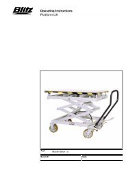
TRANSPORTTRASPORTOPacking can be lifted or moved by fork lift trucks, cranesor bridge cranes. In case of slinging, a second personmust always take care of the load to avoid dangerousoscillations.At the arrival of goods, check for possible damage due totransport operations. Also verify that all items specified inthe delivery notes are included. In case of damage orpossible defects in transit, the person in charge or thecarrier must be immediately informed. Furthermore,during loading and unloading operations goods must behandled as shown in picture 2 (when slinging, usewooden spacers to prevent carton box from damaging).PACKING REMOVALWooden packing and pluriball packing can be recycled ,in case of total packing removal, comply with the rules inforce in the lift installation country.L’imballo può essere sollevato o spostato sia con carrellielevatori che con gru o carri ponte. L’eventualeimbracatura deve essere sempre accompagnata da unapersona al fine di scongiurare pericolose oscillazioni delcarico. All’arrivo, verificare che la merce non abbiasubito danni e che ci siano tutti i pezzi indicati nella listadi spedizione. Comunicare immediatamente all’incaricatoo al trasportatore eventuali mancanze o irregolarità eeventuali danni che il sollevatore abbia subito durante iltrasporto. Rispettare al momento del carico/scarico mercei punti di presa dell’imballo come indicato in figura 2(con uso delle fasce usare distanziali di legno onde evitarelo schiacciamento delle scatole di cartone.ELIMINAZIONE DELL’IMBALLOL’imballo in legno può essere riciclato come pure il“pluriball”, nel caso di eliminazione dell’imballocomplessivo attenersi alle normative vigenti nel paese diinstallazione del sollevatore.___________________________________________________________________________6
1. LIFTING PUSH BUTTON2. LOWERING PUSH BUTTON3. LED4. MASTER SWITCH5. FINAL LOWERING PUSH BUTTON6. EMERGENCY BUTTON7. BEEPER1- Lifting push button: When pressed, motor and liftingmechanism are operated.2- Lowering push button: When pressed, loweringelectrovalves are operated.3. Led: Indicates that the control board is powered.4. Master switch: The switch can be padlocked toprevent the use of the lift during the maintenance.5-Final lowering push button: this button allow lift todo final lowering. Beeper is activated during this phase6- Emergency button: if pressed, power supply to thecontrol unit is cut off. Turn the button clockwise (see thearrows) to restart.7- Beeper: it is activated during final loweringPic.- Fig. 41. PULSANTE DI SALITA2. PULSANTE DI DISCESA3. LED4. INTERRUTTORE GENERALE5. PULSANTE DISCESA FINALE6. PULSANTE D’EMERGENZA7. SEGNALATORE ACUSTICO1-Pulsante di salita; premendolo, si attiva il motore ed imeccanismi che attuano la salita del sollevatore.2-Pulsante di discesa; premendolo, si attivano leelettrovalvole che attuano la discesa del sollevatore.3-Led; indica il funzionamento del sollevatore.4-Interruttore generale; è possibile lucchettarel’interruttore per impedirne l’uso durante le fasi diriparazione o manutenzione.5-Pulsante discesa finale; premendolo permette la fasefinale di discesa. Attiva il segnalatore acustico6-Pulsante d’emergenza; premendolo si interrompel’alimentazione elettrica alla centralina per riarmarloruotare il pulsante in senso orario secondo le frecce.7-Segnalatore acustico; segnala la discesa finale“GEMINI GLP 30” double scissor car lifts are able to liftvehicles and vans whose weight is no more than 3000 kg.All version are equipped with extension platforms sovehicles with a longer “wheel base” can be lifted. Ourrange of double scissor lifts can meet any demand comingfrom car repairmen, tyre dealers, body repairmen etc.I ponti sollevatori a doppia forbice della serie “GEMINIGLP 30” sono adatti a sollevare tutti i tipi di autovetture efurgoni con peso non superiore a 3000 kg.. Sono forniti diestensione sulla pedana che permette di sollevare senzadifficoltà anche le autovetture con “passo” più lungo. Inostri ponti sollevatori a doppia forbice possonosoddisfare le esigenze di autoriparatori, gommisti,carrozzieri ecc. con poco ingombro e grande facilitàd’uso.___________________________________________________________________________8
OVERALL DIMENSIONSDIMENSIONI DI INGOMBROWARNING: “GEMINI GLP 30” low-profile car lifthas been designed and built to lift and place car atheights in closed areas (special applications uponrequest). Any other use is forbidden, and particularly,the following operations cannot be performed:- VARNISHING, - LIFTING OF PEOPLE ORSCAFFOLDING,- SQUASHING PRESS, - CAR JACKOR WHEEL REPLACEMENT.CHARACTERISTICS• Low-voltage controls (24V).• Hydraulic-volumetric synchronism• Hydraulic system equipped with safety mechanism incase of failure due to broken or cut tubes.• Hand lowering device in case of power failure.• Acoustic signal at the end of the lowering cycle.TECHNICAL DATAGEMINI GLP 30 - PROTECTION IP54• Operation . . . . . . . . . . . .Electro-hydraulic.• Capacity . . . . . . . . . . . . .3000 kg.• Weight . . . . . . . . . . . . . .From 900 to 1000 kg.• Lifting time . . . . . . . . . . . .43 sec.• Lowering time . . . . . . . . .43 sec.• Motor . . . . . . . . . . . . . .3ph 3kw 220/380V 50Hz.• Noise level . . . . . . . . . . .
CHAPTER 3 - SAFETYGENERAL RULESRead this chapter carefully it contains importantinformation concerning the safety of the operator.The operator and the maintenance personnel arerequired to observe the accident preventionlegislation in force in the country of installation ofthe lift.CAP. 3 - SICUREZZAPRECAUZIONI GENERALIÉ molto importante leggere questo capitolo conattenzione ed in ogni sua parte poiché contieneinformazioni essenziali sui rischi che operatore emanutentore potrebbero correre in caso d'uso erratoo improprio del sollevatore. Essi sono tenuti alrispetto delle prescrizioni contenute in leggi e normeantinfortunistiche vigenti nel paese in cui è installatoil sollevatore.1 During lifting or lowering operations, the lift mustbe operated only from the operator area as shown inthe diagram (picture 7).2 Standing or passing within the danger area whenthe lift is working or the vehicle is raised is strictlyforbidden.3 The operator must make sure the hazard area isclear when lifting or lowering the lift4 Never use the lift without protection or when safetydevices are off-line.5 Always use the rubber pads when lifting a vehicle,observing the proper points of support specified bythe vehicle’s manufacturer.6 Switch off the engine and engage the parking brakeafter placing the vehicle on the car lift; Furthermore,disengage the shift lever and move it to the “neutralposition.7 To prevent the vehicle from falling make sure it isproperly placed on the lift.8 Getting in or on the vehicle and-or starting theengine when the car lift is raised is strictly forbidden.9 Never leave objects and-or obstructions under thevehicle or scattered on it during the lowering phase.10 Keep the area under/next to the lift clear andremove possible oil spots to avoid the risk of slip-1 É importante che in fase di salita o discesa delsollevatore, l’operatore agisca soltanto nella zona dicomando a lui riservata come indicato in figura 7.2 É vietato a chiunque sostare o transitare entro lazona a rischio mentre il sollevatore è azionato, ecomunque quando il veicolo è già sollevato.3 L’operatore è obbligato, durante le fasi di salita/discesa del sollevatore, ad assicurarsi che l’area arischio sia deserta.4 Non utilizzare la macchina senza le protezioni ocon le stesse disattivate o manomesse.5 Per sollevare un autoveicolo, usare i tamponi digomma in dotazione rispettando i corretti punti diappoggio consigliati dal costruttore dell’autoveicolo.6 Dopo aver posizionato l’autovettura sul sollevatorespegnere il motore ed innestare il freno distazionamento, ricordarsi di disinserire la leva delcambio posizionandola sul “folle”.7 Per evitare il rischio di caduta dell’autoveicoloprovvedere al suo corretto posizionamento.8 É vietato salire sul veicolo e/o metterlo in moto conil sollevatore innalzato.9 É vietato lasciare oggetti sotto il veicolo osparpagliati in fase di discesa del sollevatore.10 Tenere pulita la zona vicino al sollevatore pulendole macchie d’olio al fine di evitare perico-___________________________________________________________________________10
ping.11 Never use water-steam-varnish-solvent jets in thelift area, and particularly, close to the control box.12 Proper lighting is extremely important. Make sureall areas next to the car lift are well and uniformly lie,according to that specified by the applicable laws ofthe place of installation.13 Climbing on the platform when lifting the vehicleor when the same has been already raised is strictlyforbidden.14 Any use of the lift other than what hereinspecified can cause serious accidents to the operatoras well as to the people in close proximity.15 The tampering of safety devices is strictlyforbidden.16 Never exceed the maximum lifting capacity. Makesure the vehicles to be raised are without loads.17 In case of anomaly, stop the car lift and block theon/off selector by using a padlock. Only skilledtechnicians should be allowed to restart the lift. Besure the power supply is off before repairing andservicing the lift. The operator, the lift or the vehiclesraised can be seriously damaged if these instructionare not followed.SAFETY DEVICESANTI-SHEARING SAFETY. The lift is equipped with adevice that stops its lowering phase at 1,2m. from thefloor. To restart and close the lift, release the loweringbutton (2) (see pict.4), press and release the yellow reactivationbutton (5) (see pict.4), and press the loweringbutton again. During the lowering phase, the device willproduce a warning acoustic signal (beep).SAFETY VALVE FOR AUTOMATIC LOWERINGCUT OUT.Parachute valves able to automatically lock a single ordouble-acting cylinder in case a sudden increase invelocity occurs. The valves are located inside thecilynders and prevent the load from falling down in caseof sudden pipe bursting or cutting.DEAD-MAN CONTROL. The car lift is equipped with adeadman control. Lowering and lifting operations arestopped immediately by releasing push button controls.DOUBLE-CIRCUIT HYDRAULIC SAFETY. The lift isequipped with a double hydraulic system workingidependently. Each separate circuit is able to support therated charge but is not able to lift the charge. This is toguarantee that all placing (servicing) and loweringoperations can be performed even in case of a faulty line,whereas lifting operations are notlosi scivolamenti.11. É vietato usare getti d’acqua-vapore-vernicisolventi nelle zone presso il sollevatore e lacentralina di comando.12. É rischiosa un'illuminazione non idonea.Verificare che tutte le zone siano ben illuminate ed inmaniera uniforme.13. É assolutamente vietata la presenza e“l’arrampicata”sulle pedane di persone sia durante il sollevamento,sia a veicolo sollevato.14. É vietato ogni uso diverso del sollevatore daquello per cui è stato progettato, la non osservanza diquesta norma può causare incidenti anche gravi apersone e cose.15. É assolutamente vietata la manipolazione deidispositivi di sicurezza.16. É assolutamente vietato superare la capacità max.di sollevamento della macchina. Assicurarsi in talsenso che le vetture non siano cariche.17. In caso di comportamento anomalo delsollevatore, fermarlo e chiudere il selezionatoreon/off bloccandolo con un lucchetto. Il ripristino delfunzionamento deve essere fatto da personaleesperto. Prima della riparazione e manutenzione delsollevatore assicurarsi che l’alimentazione elettricasia disinserita dalla rete principale.DISPOSITIVI DI SICUREZZASICUREZZA ANTICESOIAMENTO. Il sollevatore èfornito di un dispositivo che , in fase di discesa arresta ilponte a 1,2 m da terra per ripartire e chiudere il ponteoccorre rilasciare il pulsante di discesa (2) (rif. fig. 4)premere e rilasciare il pulsante di riarmo giallo (5) (rif.fig. 4) e premere di nuovo il pulsante di discesa (2) (rif.fig. 4) nella fase di chiusura il dispositivo emetterà unsegnale acustico (beep) di avvertimento per tutta la fase didiscesa.VALVOLE DI SICUREZZA BLOCCO AUTOMATICODISCESA.Il dispositivo di sicurezza è costituito da valvole(paracadute) che bloccano automaticamente i cilindri nelcaso in cui la velocità di discesa aumenti in modoincontrollabile. Sono alloggiate all’interno dei cilindri eimpediscono la caduta del carico nel caso di scoppio otaglio accidentale delle condotte oleodinamiche.SISTEMA A “UOMO PRESENTE”. Il sollevatore èdotato di un sistema operativo del tipo “uomo presente”.Le operazioni di salita-discesa (e tutte le altre operazioni)vengono immediatamente interrotte al rilascio dei pulsantidi comando situati sulla consolle della centralina.SICUREZZA IDRAULICA CON DOPPIO CIRCUITO.Il ponte è fornito di un doppio sistema idraulicoindipendente. Ogni___________________________________________________________________________11
possible.MASTER SWITCH. The master switch (4) (pict. 4). Itdesactivates all functions. Padlock the switch to preventunauthorized personnel from using the lift.EMERGENCY STOP. By pressing the mushroom button(6) (see pict.4), power supply to the lift is cut off and allfunctions are disconnected.singolo circuito ha la capacità di sostenere il cariconominale ma non ha la capacità di sollevare il carico.Questo garantisce che se su una linea è guasta si possonocomunque effettuare con il ponte le operazione distazionamento in quota (per lavoro) e quella di discesa delveicolo ma non quella di sollevamento.INTERRUTTORE GENERALE. Lo stop d'emergenzaviene attivato tramite l'interruttore generale (4) (rif. fig. 4)esso disattiva ogni funzionalità del ponte lucchettarel'interruttore per non far usare il ponte da personaleestraneo.STOP D'EMERGENZA. Viene attivato premendo ilpulsante a fungo (6) (rif. fig. 4) esso disattival’alimentazione elettrica al ponte ed ogni sua funzionalità.___________________________________________________________________________12
CHAPTER 4 - INSTALLATIONUNPACK THE GOODS AND CHECK FORPOSSIBLE DAMAGE BEFORE INSTALLINGTHE LIFT.ONLY SKILLED TECHNICIANS, APPOINTEDBY THE MANUFACTURER, OR BYAUTHORIZED DEALERS SHOULD BEALLOWED TO INSTALL THE CAR LIFT.SERIOUS DAMAGE TO PEOPLE OREQUIPMENT CAN BE CAUSED IF THIS RULE ISNOT FOLLOWED.The lift must be installed according to the specified safedistance from walls, columns, other equipments etc. Theroom must be a minimum 4500 mm. in height. Theminimum distance from walls must be 1500 mm. takeinto consideration the necessary space to work easily.Further space for the control site and for possible runwaysin case of emergency is also necessary. (picture 8).INSTALLATION PROCEDURE1. Lift location.2. Check for power supply availability.3. Hydraulic connections.4. Electric network connection.5. Concrete base and fixing of the lift.6. Initial running.CAP. 4 - INSTALLAZIONEPRIMA DI PROCEDERE ALL’INSTALLAZIONEDEL SOLLEVATORE, TOGLIERE L’IMBALLO ECONTROLLARE LA MERCE.L’ INSTALLAZIONE DEL SOLLEVATORE É DICOMPETENZA DI TECNICI SPECIALIZZATI,INCARICATI DAL COSTRUTTORE O DAIRIVENDITORI AUTORIZZATI. LA MANCATAOSSERVANZA DI QUESTA NORMA PUÓCAUSARE SERI DANNI ALLE PERSONE EALLE COSE.Il sollevatore deve essere installato rispettando le distanzedi sicurezza da muri, colonne, altre macchine, ecc.L’altezza minima del locale deve essere di almeno 4500mm. La distanza minima dai muri, considerando lo spazioper lavorare comodamente, la centralina di comando e levie di fuga in caso di emergenza deve essere di almeno1500 mm. (rif. fig. 8)PROCEDURA DI INSTALLAZIONE.1) Posizionamento del sollevatore.2) Verifica disponibilità alimentazioni elettriche.3) Connessioni oleodinamiche.4) Allacciamento rete elettrica.5) Base cementizia e fissaggio sollevatore.6) Primo avviamento.1) LOCATION OF THE LIFT1) POSIZIONAMENTO DELSOLLEVATORE.Place the automotive lift using a crane truck or any otherlifting equipment in the desired position. Raise (to openthe lift) the two platforms using a crane, following theintructions in the picture, and place them at a height ofabout 70 cm.Insert a wooden shim to prevent the lift from closingduring the slinging phase. To move the car lift, sling it asdescribed in picture 8 and place it into the right position.Use metal shims to level the ground where necessary.Posizionare il sollevatore con l’aiuto di un carro ponte oaltro mezzo di sollevamento adeguato nel puntodesiderato.Sollevare (per aprire il sollevatore) con una gru le duepedane seguendo le indicazioni in figura per una altezzadi ca. 70 cm. inserire uno spessore di legno che impediscala chiusura del ponte quando si va ad imbracare il ponte.Per spostare il sollevatore imbracarlo come in figura 8 eposizionarlo a dovere. Procedere all’eliminazione dipiccoli dislivelli del suolo servendosi di spessorimetallici.___________________________________________________________________________13
2) CHECK FOR POWER SUPPLYAVAILABILITYThe room must be previously arranged for the powersupply of the lift. Make sure that supplies are not far fromthe power unit.2) VERIFICA DISPONIBILITÀALIMENTAZIONE ELETTRICA.Il locale deve essere preventivamente predisposto perl’alimentazione elettrica del sollevatore. Assicurarsi chegli attacchi per tale alimentazione siano disponibile neipressi della centralina.3) HYDRAULIC CONNECTIONS 3) CONNESSIONI OLEODINAMICHE___________________________________________________________________________14
HYDRAULIC PLANSCHEMA IMPIANTO OLEODINAMICO___________________________________________________________________________15
4) ELECTRIC SYSTEM CONNECTION 4) ALLACCIAMENTO RETE ELETTRICAIG MAIN SWICTH IG INTERUTTORE GENERALECM 4 KW 24 V DC CONTATOR CM CONTATTORE 4 KW 24 V DCTR 50 VA TRANSFORMER TR TRANSFORMATORE 50 VABYP BUZZER BYP CICALINOEV1 ELECTROVALVE EV1 ELETTROVALVOLAEV2 ELECTROVALVE EV2 ELETTROVALVOLAW1 STOP AND GO PROXIMETRY W1 PROXIMETRY STOP AND GOW2 STOP AND GO PROXIMETRY W2 PROXIMETRY STOP AND GOA EMERGENCY BUTTON A PULSANTE DI EMERGENZAWarning ! Only skilled personnel should beallowed to perform the operation shown below.Connect as follow:• Open the control box front panel and connect theelectric cable to the general switch cable. Beforeconnecting the electric system, make sure that the powersupply plant to the lift is equipped with the protectiondevices required by current standards in the countrywhere the lift is installed.BE CAREFULBefore accessing inside the control box, forconnection to the power or for the repair ofelectric equipments breakdown, make sure thatthe main power supply is disconnected, to avoidthe possibility of electrocution.Attenzione: Le operazioni sottoelencate devonoessere eseguite da personale qualificato.Eseguire l’allacciamento di potenza alla centralina dicomando come segue:• Aprire il pannello frontale della centralina e allacciare,il cavo di alimentazione elettrica al cavo collegatoall’interruttore generale. Assicurarsi che la linea dialimentazione elettrica sia adeguatamente protetta dainterruttore magnetotermico con capacità e caratteristicheadeguate e conforme alle normative vigenti di sicurezza.ATTENZIONE!Prima di agire all’interno della centralina dicomando, per l’allacciamento alla rete elettrica oper la riparazione di un guasto agli apparatielettrici, assicurarsi che l’alimentazione elettricaprincipale sia disinserita evitando così lapericolosa possibilità di folgorazione.Collegare i cavi dei sensori provenienti dalle due pedaneai morsetti della scheda elettrica come segue:Connect sensor cables of two platforms to the terminalson PC board as follow:Platform P1 Terminal 11 Brown wire Pedana P1 Morsetto 11 Filo marronePlatform P1 Terminal 12 White or black wire Pedana P1 Morsetto 12 Filo bianco o neroPlatform P1 Terminal 13 Green or blue wire Pedana P1 Morsetto 13 Filo verde o bluPlatform P2 Terminal 14 Brown wire Pedana P2 Morsetto 14 Filo marronePlatform P2 Terminal 15 White or black wire Pedana P2 Morsetto 15 Filo bianco o neroPlatform P2 Terminal 16 Green or blue wire Pedana P2 Morsetto 16 Filo verde o blu___________________________________________________________________________16
6) LIFT FIXING 6) BASE CEMENTIZIA E FISSAGGIOSOLLEVATORE6) LIFT FIXINGAfter checking that electric and hydraulic connections areproperly made (see pictures 9/10/11), make sure the twobases of the lift are levelled.The concrete floor must have a strength to 20N/mm2 min.compression and 200mm min. thickness, to have 95mmmin. anchorage depth.When using the standard M10x100mm rods thefloor must be perfectly levelled.Drill four 16mm dia. holes per base in the concrete floorusing the base holes as a guide.•Concrete thickness required : 200mm.•Hole depth : 115mm.•Distance between holes and concrete base : 150mm.Insert the tie rod into the hole till the washer and the headof the screw contact the base. Tighten the rods to a200Nm torque. If the rods cannot bear the specified200Nm torque, replace the concrete under the base with areinforced concrete block having the followingspecifications:•dimension: 2500mm x 2500mm 200mm (thickness).•Strength : 25Nm/mm2•lower reinforcing net : dia. 10mm / 20cm / 20cm.•upper reinforcing net : dia. 10mm /20cm / 20cm. Steel•improved adhesion steel : Fe B44K typeLevel the surface. Let it harden before installing the lift.6) BASE CEMENTIZIA E FISSAGGIOSOLLEVATOREDopo aver eseguito i collegamenti elettrici edoleodinamici (rif. fig. 9/10/11), assicurarsi che gli stessisiano effettuati in modo corretto e che le due basi delsollevatore siano perfettamente parallele.Il pavimento cementizio deve avere una resistenza acompressione minima di 20 N/mm2 ed uno spessoreminimo di 200 mm in modo da avere una profondità diancoraggio di minimo 95 mm. Usando i tiranti standardM10x100 mm il pavimento deve essere perfettamente inpiano.Forare 4 fori per base da 16 mm di diametro nelpavimento cementizio usando i fori della base comeguida.•Spessore richiesto cemento 200 mm.•Profondità fori 115 mm.•Distanza dei fori dal bordo del massetto cementizio 150mm.Inserire il tirante dentro il foro finchè rondella e testadella vite non toccano la base. Serrare i tiranti con unacoppia di a 200 Nm. Se i tiranti non sopportano unacoppia di 200Nm sostituire il cemento sotto la base conun blocco di cemento armato delle seguenticaratteristiche:•dimensione 2500 mm x 2500 mm x 200 mm (spessore).•resistenza di 25N/mm2.•rete di armatura inferiore dia. 10mm / 20cm x 20cm.•rete di armatura superiore dia. 10mm / 20cm x 20cm diacciaio.•acciaio aderenza migliorata tipo Fe B44KPareggiare a filo il pavimento. Lasciare indurire prima diinstallare il sollevatore.___________________________________________________________________________17
7) FIRST STARTINGWarning! Only skilled and authorized personnelshould be allowed to perform these operations.Carefully follow all instructions shown below toprevent possible damage to the car lift or risk ofinjury to people.Be sure that the operating area is cleared ofpeople.After positioning the lift as specified and performingelectric and hydraulic connections, the lift can be operatedby following the specific procedure.Open the front door of the control box and unscrew the oiltank cap. Using a funnel, pour 15 liters of hydraulic oilwith a grade of viscosity 32 CST or equivalent. Move themaster switch to the “1” position (pos. 4 pict. 4) and pressthe lifting button (pos. 1, pict. 4). If the lift does notoperate but the motor runs regularly, check the motor forproper direction of rotation and switch the phases on thepower supply line in necessary. Press the button againuntil platforms are fully lifted..Open the bleed screws (1) on the A2-B2 pistons (pict. 13)and close them again after bleeding air from the pistons .Open the OM A2/OM B2 manual operators half a turn(pict. 10-15), press the lifting button to motor stress, thenopen the bleed screws again (1) (pict. 13) to bleed airfrom the cylinders.After tightening the bleed screws, repeat the operationto make sure there is no air in the circuit. Close the OMA2 / OM B2 manual operators, lower the lift to the round,and perform several cycles with the lift unloaded to checkthere are no oil leaks and plate-forms are properlylevelled.Press the lowering button to lower the lift (see pict. 4pos.2).Performs the lifting/lowering operations 4/5 times.7) PRIMO AVVIAMENTOAttenzione! Tutte queste operazioni devono essereeseguite da personale esperto ed autorizzato.Seguire attentamente le indicazioni al fine dievitare danni alle persone e al sollevatore.Assicurarsi che l’area di rischio sia deserta.Dopo aver posizionato il sollevatore come descritto edaver effettuato i collegamenti elettrici ed idraulici, si puòprocedere alle operazioni necessarie per il funzionamentodel sollevatore.Aprire lo sportello anteriore della centralina di comando esvitare il tappo del serbatoio olio, con un imbutointrodurre 15 litri di olio idraulico con viscosità 32 CST oaltro di tipo equivalente.Portare in pos. 1 l’interruttore generale (pos. 4 fig. 4),premere il pulsante di salita (pos. 1 fig. 4) se il sollevatorenon si muove ma il motore, gira regolarmente, assicurarsiche lo stesso abbia il giusto senso di rotazione, nel casocontrario invertire le fasi sulla linea di alimentazioneelettrica. premere nuovamenteil pulsante fino alla salita completa delle pedane.Aprire le viti di spurgo (1) sui pistoni A2-B2 (rif. fig. 13)e richiuderle dopo aver fatto uscire aria dai pistoni, apriredi mezzo giro gli operatori manuali OM A2/OM B2 (rif.fig. 10-14) premere il pulsante di salita fino a quando ilmotore non va in sforzo , aprire di nuovo le viti di spurgo(1) (rif. fig. 13) per eliminare depositi d’aria nei cilindri.Dopo aver richiuso le viti di spurgo ripetere l’operazionefino a quando si è sicuri che non vi sia più aria nelcircuito. chiudere gli operatori manuali OM A2 / OM B2e portare a terra il sollevatore fare alcuni cicli a vuoto econtrollare che non vi siano perdite d’olio e che il ponteoperi con le pedane livellate.Per far scendere il sollevatore premere il pulsante didiscesa (vedi fig. 4 pos.2). Eseguire le operazioni disalita/discesa per quattro/cinque cicli.___________________________________________________________________________18
CHAPTER 5 - OPERATIONDRIVING SEQUENCECAP. 5 - FUNZIONAMENTOSEQUENZA DI FUNZIONAMENTOBe sure the platforms are fully closed before gettingon/off the lift. Get in the vehicle and drive on the lift;be sure the vehicle is centred and both rear and frontwheels are properly positioned, place the properrubber pads on the platform (picture 14) so that theyare in line with the lifting points specified by themanufacturer. Press the “lifting” button, keep it presseduntil the required height is reached. To lower the lift,press the “lowering” button (picture 4, pos.2).During the lowering phase, the lift will produce a safetyacoustic signal.During the first hours of operation cracking noisescould occur. This is due to the natural settlement ofmechanical parts and will disappear during thefollowing hours of operation.CHECKSPerform the following checks when operating the car lift:• Carefully check the car lift and its load duringlifting/lowering operation.• Check the warning acoustic signal operation of thecar lift during lowering phase.• ATTENTION: When the lift is operating, there highpressure in the hydraulic pipes (270 bar max).If the plat-forms do not start simultaneously, this might bedue to the following causes :air in the A2 or B2 cylinder and/or differentiated servicepressure in the A2 o B2 line. In this case, repeat theprevious procedure while pistons are at their max. height,operating on the two lines alternatively several times tobleed air and balance the service pressure.Prima di salire/scendere con l’autovettura dal sollevatore,assicurarsi che le pedane siano completamente chiuse.Salire con l’autovettura sul sollevatore moltolentamente assicurandosi che la stessa sia ben centratasulle pedane.Piazzare gli appositi tamponi in gomma sulla pedanadel sollevatore (vedi fig. 14) rispettando i punti disollevamento consigliati dal costruttoredell’autovettura. Premere il pulsante di “salita” e portareil sollevatore all’altezza desiderata.Per la discesa, Premere il pulsante “discesa” (fig. 4 pos 2).Durante la fase di discesa il sollevatore emetterà unsegnale acustico di sicurezza.Nelle prime ore lavorative del sollevatore, potrebberoverificarsi rumori o cigolii dovuti al non ancoraavvenuto assestamento naturale delle partimeccaniche, questo inconveniente sparirà da solo nellesuccessive ore lavorative del sollevatore.CONTROLLIEseguire i seguenti controlli durante il funzionamento delsollevatore:• In fase di salita/discesa osservare costantemente ilsollevatore e il suo carico.• Controllare il funzionamento del segnale acustico diavvertimento nella fase di discesa del sollevatore.• ATTENZIONE: Quando il ponte lavoro c'è altapressione nei tubi idraulici (270 bar max)Qualora si verificasse la partenza slivellata di una delledue pedane, le cause potrebbero essere:aria dei cilindri A2 o B2 e/o pressione di eserciziodifferenziata nelle due linee A2 o B2. In questo casoripetere le operazioni precedenti tenendo presente chel'operazione di spurgo va fatta con i pistoni allamassima altezza, insistendo più volte e alternativamentesu entrambe le linee in modo da liberarle dall'aria edequilibrare le pressioni di esercizio.___________________________________________________________________________19
CHAPTER 6 - MAINTENANCEWARNING! Only skilled and previously authorizedpersonnel should be allowed to service the lift. Whenservicing the lift, all safety precautions must befollowed to avoid accidental starting of the machine.The master switch must be padlocked in “zero”position. The key should be kept by the maintenancetechnician throughout the service. During serviceoperations,all safety instructions reported in chapter,“SAFETY”, must always be followed.PERIODIC MAINTENANCEMaintenance operations must be performed at eachspecified maintenance period in order to keep the car liftin perfect working condition. The manufacturer is notliable for possible damage resulting from failure to followthe above instructions.• Car lift must be cleaned once a month, at least, withoutusing chemical agents and hight pressure washing guns.Always dispose of used brake oil to prevent possibledamage to the finish. Carefully check that piston rodsare not damage sinced inside gaskets and seals couldbe seriously damaged and leakage of oil occur.• Check safety devices for proper working conditionperiodically.• Grease roller slideways periodically.• Check flexible tubes for proper conditions yearly.• Change oil in the hydraulic system at 5 year intervals, atleast. Used oil drained from the system during oilchange operations should be treated as a highlypollutant product. Always dispose of used oil asspecified by the law in force in the country where thecar lift is installed.• Balance the hydraulic circuit periodically. In case ofleaking, proceed as follows:Raise the lift unloaded to1m height, open the OMA2 -OMB2 manual operators in a sequential order (pict. 15)and close them again to balance possible leakingbetween the A1 - A2 and B1 - B2 line (pict. 10)MACHINE DEMOLITIONWhen demolishing the machine all safety precautionsspecified in chapter “3”-”4” must be followed. Onlyauthorized technicians should be allowed to perform thisoperation. Metallic parts can be scrapped as “scrap iron”.In any case, demolished material must be eliminatedaccording to the effective laws of the country where thecar lift is installed. It must be remembered that, for fiscalpurposes, any demolition operation must be properlydocumented as specified by the effective laws of thecountry where the lift is installed at the time ofdemolition.CAP. 6 - MANUTENZIONEATTENZIONE! La manutenzione deve essereaffidata esclusivamente al personale autorizzato.Durante la manutenzione del sollevatore è necessarioadottare tutti i provvedimenti utili per evitarnel’avviamento accidentale. L’interruttore generaledeve essere bloccato in posizione “0” mediantelucchetto. La chiave deve essere custodita dalmanutentore per tutta la durata dell’intervento.Ovviamente bisogna rispettare tutte le indicazioni egli obblighi riportati nel capitolo SICUREZZA.MANUTENZIONE PERIODICA.Per mantenere il sollevatore in piena efficienza, ènecessario rispettare le tempistiche di manutenzioneindicate. Il mancato rispetto di quanto sopra solleva ilcostruttore da qualunque responsabilità agli effettidella garanzia.• Il sollevatore deve essere pulito almeno una volta almese non usando aggressivi chimici e pistola ad acqua adalta pressione. Attenzione all’olio dei freni, se non vienesubito eliminato rischia di rovinare irrimediabilmentela verniciatura. É importante che lo stelo dei pistonivenga preservato da eventuali impurità chepotrebbero danneggiarlo, ciò potrebbe portare adun’usura prematura o peggio ad una rottura delleguarnizioni interne causando una pericolosa perdita diolio.• Controllare periodicamente lo stato degli apparati disicurezza.• Lubrificare periodicamente con grasso le guide discorrimento rulli.• Controllare annualmente lo stato dei tubi flessibili adalta pressione.• Cambiare l’olio dell’impianto idraulico almeno ogni 5anni. L’olio esausto che viene estratto dall’impiantodurante il cambio d’olio, deve essere trattato comeprodotto inquinante, pertanto dovrà essere smaltitosecondo le prescrizioni della legislazione vigente nelpaese in cui è stato installato il sollevatore.• Riequilibrare periodicamente il circuito idraulico aseguito trafilamento procedere come segue:Potare il ponte senza carico ad un metro d’altezza, apriresequenzialmente gli operatori manuali OMA2 - OMB2(rif. fig. 15) e poi richiuderli in questo modo siriequilibrano i possibili trafilamenti tra linea A1 - A2 eB1 - B22 (rif. fig. 10)DEMOLIZIONE DELLA MACCHINA.Durante la demolizione della macchina devono essereosservate tutte le precauzioni di sicurezza adottate neicapitoli “3”, “4”. La demolizione della macchina deveessere effettuata da tecnici specializzati come per ilmontaggio. Le parti metalliche possono essere rottamate ecatalogate come rottami ferrosi. In ogni caso tutti imateriali derivati dalla demolizione devono esseresmaltiti in accordo alla normativa vigente nel paese in cuiil sollevatore è installato. Si ricorda che ai fini fiscali,occorre documentare l’avvenuta demolizione producendodenunce e documenti secondo la legislazione vigente nelpaese di installazione del sollevatore.___________________________________________________________________________20
CHAPTER 7 - TROUBLESHOOTINGTroubleshooting and possible repairs requireabsolutecompliance with all safety precautions indicated inchapters 3 and 6.MANUAL LOWERINGCAP. 7 - INCONVENIENTI E RIMEDILa ricerca dei guasti e gli eventuali interventi diriparazione richiedono il rispetto di tutte leprecauzioni di sicurezza indicate al cap. “3” ed alcap.”6”.DISCESA MANUALEIf the car lift cannot perform lowering operations becauseof power supply interruption, faulty hydraulic valves orelectric trouble in the system, the lift can be loweredmanually. For manual lowering operation (emergency),perform the following:• Make sure there are no obstacles blocking the loweringphase; remember that the car lift may not be liftedagain to remove possible obstacles.• Disconnect main power supply.• Loosen the manual operators (OM) (A1-B1) (seepict.15) 1/2 turn.• Emergency lowering has started; speed can be increasedor decreased according to the opening of screws.• Constantly check the area around the car lift, and tightenthe (OM) (A1-B1) screws in case of danger or in case thelowering phase should be interrupted.• During the manual lowering phase, the presence of theoperator is required in close contact with the lowering keyin order to ensure immediate closing of screws andblocking of the lowering phase in case of danger (if theoperator were not close to the key, his reaction would notbe immediate and this might cause damage to personsand equipment).NOTE: manual lowering (emergency) operationsshould be performed by authorized personnel,specially trained for operating the car lift, only.In caso di mancanza di energia elettrica o di guasto allevalvole idrauliche o guasto elettrico all’impianto ed ilponte non scende più, è possibile in questo caso operaremanualmente per far discendere il ponte. Per la discesamanuale (emergenza) operare come segue:• Controllare che non vi siamo impedimenti, ostacoli chebloccano la discesa; ricordarsi che poi non sarebbe piùpossibile rialzare il ponte e rimuovere l’ostacolo.• Scollegare l’alimentazione elettrica generale.• Allentare gli operatori manuali (OM) (A1-B1) (rif. fig.15) di 1/2 giro• La discesa di emergenza è iniziata aprendo più o menole viti si aumenta o diminuisce la velocità• Controllare costantemente lo spazio intorno al ponte eserrare le viti (OM) (A1-B1) qualora si verifichi unasituazione di pericolo o la necessità di bloccare la discesadel ponte.• Per operare la discesa manuale e necessaria la presenzadell’uomo e a contatto della chiave che opera la discesa,questo per aver un immediata chiusura delle viti el’arresto della discesa immediato in fase di pericolo (sel’uomo che opera stesse lontano dalla chiave il tempo direazione e chiusura non sarebbe immediato e potrebbecausare danni a persone e cose).N.B. la discesa manuale (emergenza) deve essereeffettuata solamente da persone autorizzate eaddestrate sul funzionamento del ponte.___________________________________________________________________________21
TROUBLESHOOTINGSYMPTOM 11) The lifting button is pressed, the car lift does not moveand the motor does not run.POSSIBLE CAUSE 1:1A) The main switch is off.REMEDY - Check and activate.1B) Power supply is interrupted.REMEDY - Check and activate.1C) The motor contactor is faulty.REMEDY - Check the contactor coil operation andmake sure it is activated when supplied with 24V.1D) Blown fuse on 24 volt power supply.REMEDY - Check the fuse on the transformer andreplace it if necessary.1E) Faulty transformer.REMEDY - Check the input and output voltage of thetransformer: in. 380 V, out. 24 V.1F) The motor thermic switch is activated foroverheating.REMEDY - Wait for 10 minutes and try starting again;then, using a tester, make sure the contact is closedagain.SYMPTOM 22) The lifting button is pressed, the motor runs but the carlift does not move.POSSIBLE CAUSE 2:2A) Wrong rotation direction.REMEDY - Switch the phase and that the motor turnsin the direction indicated by the arrow..2B) The load to lift is too heavy, the MAX PRESSUREvalve (pos. 4 picture 10) is discharged.REMEDY - The lift is being used with an exceedingload, beyond the specified loading capacity.2C) The oil level in the tank is too low.REMEDY - Check the oil level by using the specificcap/dipstick and refill.2D) One or both manual operators (A1-B1) (ref. pict. 15)on the hydraulic block are open.REMEDY - Check and tighten the srews.2E) The lowering valve gaskets (OR) on the block aredamaged or loose.REMEDY - Check the gaskets and replace if necessary.2F) One or both manual operators (A2-B2) (ref. pict. 15)on the hydraulic block are open.REMEDY - Check and tighten the srews.2G) Oil filter is clogged.REMEDY - Check and clean.2H) Faulty hydraulic pump.REMEDY - Check that oil comes out from one of theA1-A2 outlets on the hydraulic block after disconnectingthe corresponding pipe. Replace the pump if oil does notcome out from the A1-A2 outlets.2I) Blocked cylinders .REMEDY - Contact technical assistance.DIAGNOSTICASINTOMO 11) Pulsante di salita premuto ed il ponte è fermo il motorenon gira.PROBABILE CAUSA 1:1A) Interrutore generale chiuso.RIMEDIO - Controllare e ripristinare.1B) Alimentazione interrotta.RIMEDIO - Controllare e ripristinare.1C) Contattore motore guasto.RIMEDIO - Controllare che la bobina del cotattatorefunzioni e che il cotattatore si inneschi quando vienealimentato a 24 volt.1D) Fusibile saltato sull’alimentazione 24 volt.RIMEDIO - Controllare ed eventualmente sostituire ilfusibile presente sul trasformatore.1E) Trasformatore guasto.RIMEDIO - Controllare la tensione d’ingresso e di uscitadel trasformatore in. 380 V, usc. 24 V.1F) Termico protezione motore intervento perriscaldamento del medesimo.RIMEDIO - Attendere 10 minuti e provare a ripartire,controllare successivamente con un tester che il contattosia chiuso.SINTOMO 22) Pulsante di salita premuto il motore gira ma il ponterimane fermoPROBABILE CAUSA 2:2A) Rotazione del motore al contrarioRIMEDIO - invertire la fase e controllare che il motoregiri nel senso indicato dalla freccia.2B) Il carico da sollevare è troppo pesante la valvola diMAX PRESSIONE (pos. 4 fig. 10) va in scarico.RIMEDIO - Si sta usando il ponte oltre la sua capacitàdi carico.2C) Il livello dell’olio nel serbatoio è troppo basso.RIMEDIO - Controllare la quantità tramite il tappo conl’asta d’ispezione e rimboccare l’olio.2D) Una o tutte e due gli operatori manuali (A1-B1) (rif.fig. 15) sul blocco idraulico son aperti.RIMEDIO - Controllare e serrare le viti.2E) Le guarnizioni (OR) sulle valvole di discesa presentisul blocco sono danneggiati o trafilano.RIMEDIO - controllare le guarnizioni e sostituire senecessario.2F) Una o tutte e due gli operatori manuali (A2-B2) (rif.fig. 15) sul blocco idraulico son aperti.RIMEDIO - Controllare e serrare le viti.2G) Filtro olio otturato.RIMEDIO - Controllare e pulire.2H) Pompa idraulica guasta.RIMEDIO - Controllare che esca dell’olio da una delleuscite A1-A2 sul blocco idraulico dopo aver distaccatoil relativo tubo. Sostituire la pompa se non esce oliodalle uscite A1-A2___________________________________________________________________________22
SINTOMO 33) The lowering button is pressed but the lift does notlower.POSSIBLE CAUSE 3:3A) Make sure there are no obstacles blocking thelowering phase.REMEDY - Remove the obstacle and carefully checkthe area before operating the lift.3B) Make sure the main switch is on and power supply isnot interrupted.REMEDY - Check and supply power to the car lift.3C) Blown fuse on the 24V power supply.REMEDY - Check and replace the fuse after eliminatingthe cause of the short-circuit.3D) Faulty transformer.REMEDY - Check the input and output voltage of thetransformer: in. 380 V, out. 24 V.3E) Valve coils are faulty or not supplied.REMEDY - Check whether valves are activated with24V directed to the coils.3F) Damaged or faulty valves.REMEDY - Unscrew the valves on the hydraulic blockone by one and make sure they move freely whensupplied with 24 volt solenoids.3G) Faulty lowering block proximetry, broken cable orimproperly connected to the cardREMEDY - Check the proximetry and replace it ifnecessary.SYMPTOM 44) The lift is closed but one of the two platforms is higher.POSSIBLE CAUSE 4:4A) Make sure there are no obstacles blocking the closingphase.REMEDY - Remove the obstacle and carefully checkthe area before operating the lift.4B) Platforms are not levelled.REMEDY - Should this problem occur, check the car liftfirst, and check for oil leaks from cylinders or pipes.To level the platforms, perform the following (ref. pict.15) :• Loosen the screws (A2-B2) 1/2 turn.• Press the “Lowering ” button and wait until platformsare levelled.• If the car lift does not move, loosen the screws (A1-B1).• Tighten the screws (A2-B2) and (A1-B1) in case theywere used.SYMPTOM 55) The lift does not stop at 250 mm from the ground butkeeps lowering, producing a warning signal during thelowering phasePOSSIBLE CAUSE 5:5A) Faulty or improperly installed proximetry.REMEDY - Check the proximetry and replace it ifnecessary.2I) Cilindri bloccati .RIMEDIO - Contattare l’assistenza tecnica.SINTOMO 33) Pulsante di discesa premuto ed il ponte non scende.PROBABILE CAUSA 3:3A) Controllare che non vi siano ostacoli cheimpediscono la discesa.RIMEDIO - Rimuovere l’ostacolo prestare comunquemassima attenzione prima di eseguire manovre con ilponte.3B) Controllare che l’interruttore generale sia attivato eche l’alimentazione non sia interrotta.RIMEDIO - Controllare ed eventualmente inserirecorrente al ponte.3C) Fusibile saltato sull’alimentazione 24 volt.RIMEDIO - Controllare ed eventualmente sostituire ilfusibile dopo aver eliminato la causa del corto.3D) Trasformatore guasto.RIMEDIO - Controllare la tensione d’ingresso e di uscitadel trasformatore in. 380 V, usc. 24 V.3E) Le bobine sulle valvole difettose o non alimentate.RIMEDIO - Controllare se con 24 volt diretti sullebobine, le valvole vengano attivate.3F) Valvole guaste o difettose.RIMEDIO - Svitare una valvola alla volta dal bloccoidraulico e controllare dce siano libere di muoversiquando vengono alimentate tramite i solenoidi con 24volt.3G) Proximetri di stop discesa guasto o cavo tagliato onon perfettamente connesso alla scheda.RIMEDIO - Controllare ed eventualmente sostituire ilproximetri.SINTOMO 44) Il ponte è chiuso è una delle due pedane rimane piùalta.PROBABILE CAUSA 4:4A) Controllare che non vi siano impedimenti o ostacoliche blocchino la chiusura.RIMEDIO - Rimuovere l’ostacolo e prestare comunquemassima attenzione prima di eseguire manovre con ilponte.4B) Dislivello delle pedane.RIMEDIO - Se dovesse comparire questo problema,per prima cosa controllare e verificare il sollevatore,controllare che non vi siano perdite d’olio dai cilindri odai tubi.Per rilivellare le pedane operare come segue (rif. fig.15) :• Allentare le viti (A2-B2) di 1/2 giro.• Premere il tasto “Discesa” e aspettare che le pedanesi rilivellano.• Se il ponte Rimane fermo allentare le viti (A1-B1).• Serrare le viti (A2-B2) e le viti (A1-B1) qualora siastato necessario il loro utilizzo.___________________________________________________________________________23
SINTOMO 55) Il ponte non esegue lo stop a 1,2 m da terra madiscende sempre emettendo un segnale acusticocontinuo per tutta la fase di discesa.PROBABILE CAUSA 3:5A) Proximetri di stop discesa non perfettamenteposizionato o guasto.RIMEDIO - Controllare ed eventualmente sostituire ilproximetri.___________________________________________________________________________24
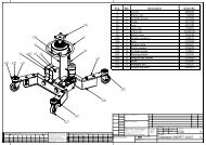
CHAPTER 8 - ACCESSORIESAvailable accessories:Set of tube extensions (2m). Rubber supports. T4B rubberpads.Standard colors: RAL 5015 - RAL 3002.Special colors and cold galvanizing are available uponrequest.CHAPTER 9 - SPARE PARTSSpare parts replacement and repair works should beperformedin compliance with all safety rules indicated in chapter s 3and6.Spare parts ordering procedure.When ordering spare parts the following must be clearlyspecified:• Car lift serial number and year of manufacturing .• Code of the part requested (Refer to the codes in thetable).• Quantity needed.• Spare parts must be ordered directly to themanufacturer.• Specify the colour requested, (R-RED, B-BLUE, RP-RAL PARTICULAR).Spare parts must be ordered directly to themanufacturer.PICT. 16 BASECAP. 8 - ACCESSORIAccessori disponibili sono:Set prolunghe tubi (2 mt.). Supporti in gomma. Tamponiin gomma T4B.I colori standard sono: RAL 5015 - RAL 3002. Arichiesta si possono avere colori speciali e zincatura afreddo.CAP. 9 - PARTI DI RICAMBIOLa sostituzione delle parti di ricambio e gli interventi diriparazionerichiedono il rispetto di tutte le precauzioni di sicurezzaindicate ne capitolo “3” e nel cap.”6”. Procedura perl’ordinazionedelle parti di ricambio:Per ordinare le parti di ricambio necessarie occorre:• Indicare il numero di matricola del sollevatore el’anno dicostruzione.• Indicare il codice del pezzo richiesto (vedere nellatabella lacolonna codice).• Indicare la quantità richiesta.• Indicare il colore richiesto, (R-ROSSO, B-BLU, RP-RAL PARTICOLARE).La richiesta deve essere fatta direttamente alla casacostruttrice.FIG. 16 BASE___________________________________________________________________________25
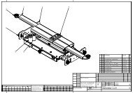
PICT. 17 BOOMSFIG. 17 BRACCI___________________________________________________________________________26
___________________________________________________________________________27
PICT. 18 MECHANICAL SAFETYDEVICES – PISTONSFIG. 18 SICUREZZE MECCANICHE -PISTONI___________________________________________________________________________28
PICT. 19 PLATFORMFIG. 19 PEDANA___________________________________________________________________________29
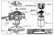
PICT. 20 CONTROL BOXFIG. 20 CENTRALINAPos Codice Description Q.ty Pos Codice Descrizione Q.tà1 60-0086 Main switch 1 1 60-0086 Interruttore generale 12 10-973 Control unit frame 1 2 10-973 Telaio centralina 13 10-974 Side panel 4 3 10-974 Sportello laterale 44 10-975 Control unit consol support 1 4 10-975 Supporto testata centralina 15 10-986 Control unite console 1 5 10-986 Testata centralina 16 10-254 Oil tank 1 6 10-254 Serbatoio olio 17 60-0096 Electric motor 3 KW 1 7 60-0096 Motore trifase 3 KW , 230-400V 18 40-0193 Hydraulic pump 1 8 40-0193 Pompa AP100/5.0 D318 19 40-0021 Tank plug 1 9 40-0021 Tappo serbatoio 110 60-0259 Fuse 5A 1 10 60-0259 Fusibile 5A 111 40-0575 Hydraulic group 1 11 40-0575 Blocco idraulico GLP 1___________________________________________________________________________30
12 10-215 Oil tank cover 1 12 10-215 Coperchio serbatoio 113 40-0027 Suction filter 1 13 40-0027 Filtro aspirazione 114 00-40050 Coupling 1 14 00-40050 Giunto ND 48 115 60-0144 Transformer 50 VA 1 15 60-0144 Trasformatore 50 VA 116 60-0097 Motor contactor 1 16 60-0097 Contattore 4KW 24 V CC 3P 117 60-0077 Fuse 16A 4 17 60-0077 Fusibile CH 10 16 A 418 60-0198 Fuse 1A 1 18 60-0198 Fusibile 1A 119 60-0114 Push button 3 19 60-0114 Pulsante plastica nero 320 60-0673 Electric card T039 1 20 60-0673 Scheda elettrica T039 121 60-0116 Emergency button 1 21 60-0116 Pulsante di emergenza 122 60-0324 Fuse holder 1 22 60-0324 Porta fusibili 1___________________________________________________________________________31
MAINTENANCE BOOKINITIAL TESTLIBRETTO METROLOGICOVERIFICA INIZIALE___________________________________________________________________________32
MAINTENANCE BOOKINITIAL TESTLIBRETTO METROLOGICOVERIFICA INIZIALE___________________________________________________________________________33
PERIODICAL OR OCCASIONAL VISITVERIFICA PERIODICA OOCCASIONALE___________________________________________________________________________34
PERIODICAL OR OCCASIONAL VISITVERIFICA PERIODICA OOCCASIONALE___________________________________________________________________________35
TESTS TO BE MADE BY THE USERTESTS DURING USEVERIFICA DA PARTEDELL’UTILIZZATORECONTROLLI DURANTE L’UTILIZZOMONTHLY TESTSCONTROLLI MENSILIHALF-YEARLY TESTSCONTROLLI SEMESTRALI___________________________________________________________________________36
REPAIRRIPARAZIONEREPAIRRIPARAZIONE___________________________________________________________________________37