
You also want an ePaper? Increase the reach of your titles
YUMPU automatically turns print PDFs into web optimized ePapers that Google loves.
HYDRO-DRIVE SOD CUTTER<br />
OPERATOR’S/PARTS MANUAL<br />
SCH-12/5.5 - S.N. 000101 & UP; SCH-12/8.0 - S.N. 000101 & UP<br />
SCH-16/5.5 - S.N. 000101 & UP; SCH-16/8.0 - S.N. 000101 & UP<br />
SCH-18/5.5 - S.N. 000101 & UP; SCH-18/8.0 - S.N. 000101 & UP<br />
SCH-20/5.5 - S.N. 000101 & UP; SCH-20/8.0 - S.N. 000101 & UP<br />
SCH-<strong>24</strong>/8.0 - S.N. 000101 & UP<br />
Schiller Grounds Care, Inc.<br />
1028 Street Road • Southampton, PA 18966<br />
Telephone: 1-800-366-6268 • Teléfono: + (877) 596 6337<br />
Model SCH-18 shown<br />
Modelo SCH-18 ilustrado<br />
CORTADOR DE TEPE MANUAL<br />
DEL OPERADOR/PIEZAS<br />
SCH-12/5.5 - S.N. 000101 Y SIG; SCH-12/8.0 - S.N. 000101 Y SIG<br />
SCH-16/5.5 - S.N. 000101 Y SIG; SCH-16/8.0 - S.N. 000101 Y SIG<br />
SCH-18/5.5 - S.N. 000101 Y SIG; SCH-18/8.0 - S.N. 000101 Y SIG<br />
SCH-20/5.5 - S.N. 000101 Y SIG; SCH-20/8.0 - S.N. 000101 Y SIG<br />
SCH-<strong>24</strong>/8.0 - S.N. 000101 Y SIG
TABLE OF CONTENTS<br />
INTRODUCTION . . . . . . . . . . . . . . . . . . . . . . . . . . . . . . . . . . 1<br />
Thank You. . . . . . . . . . . . . . . . . . . . . . . . . . . . . . . . . . . . . 1<br />
Read This <strong>Manual</strong> . . . . . . . . . . . . . . . . . . . . . . . . . . . . . . 1<br />
Warranty . . . . . . . . . . . . . . . . . . . . . . . . . . . . . . . . . . . . . . 1<br />
Measurements. . . . . . . . . . . . . . . . . . . . . . . . . . . . . . . . . . 1<br />
Serial Numbers . . . . . . . . . . . . . . . . . . . . . . . . . . . . . . . . . 1<br />
Directions . . . . . . . . . . . . . . . . . . . . . . . . . . . . . . . . . . . . . 1<br />
OWNER’S RECORD . . . . . . . . . . . . . . . . . . . . . . . . . . . . . . . 1<br />
PRE-DELIVERY CHECK LIST. . . . . . . . . . . . . . . . . . . . . . . 1<br />
DELIVERY CHECK LIST . . . . . . . . . . . . . . . . . . . . . . . . . . . 1<br />
SAFETY . . . . . . . . . . . . . . . . . . . . . . . . . . . . . . . . . . . . . . . . . 2<br />
Handle Fuel Safely - Avoid Fires . . . . . . . . . . . . . . . . . . . 2<br />
Read Safety Signs. . . . . . . . . . . . . . . . . . . . . . . . . . . . . . . 2<br />
Operate Safely . . . . . . . . . . . . . . . . . . . . . . . . . . . . . . . . . 2<br />
Protect Children . . . . . . . . . . . . . . . . . . . . . . . . . . . . . . . . 2<br />
Avoid Tipping. . . . . . . . . . . . . . . . . . . . . . . . . . . . . . . . . . 2<br />
Operate Safely On Slopes . . . . . . . . . . . . . . . . . . . . . . . . 2<br />
Practice Safe Maintenance . . . . . . . . . . . . . . . . . . . . . . . . 2<br />
Start Engine Safely. . . . . . . . . . . . . . . . . . . . . . . . . . . . . . 2<br />
ENGINE STARTING PROCEDURES . . . . . . . . . . . . . . . . . . 2<br />
Engine Oil Level Check . . . . . . . . . . . . . . . . . . . . . . . . . . 2<br />
Transmission Oil Level Check . . . . . . . . . . . . . . . . . . . . . 2<br />
Hydro Reservoir Level Check . . . . . . . . . . . . . . . . . . . . . 2<br />
Starting Engine . . . . . . . . . . . . . . . . . . . . . . . . . . . . . . . . . 2<br />
Stopping Engine . . . . . . . . . . . . . . . . . . . . . . . . . . . . . . . . 3<br />
OPERATING THE SOD CUTTER. . . . . . . . . . . . . . . . . . . . . 3<br />
Preparation . . . . . . . . . . . . . . . . . . . . . . . . . . . . . . . . . . . . 3<br />
Operating . . . . . . . . . . . . . . . . . . . . . . . . . . . . . . . . . . . . . 3<br />
GENERAL MAINTENANCE . . . . . . . . . . . . . . . . . . . . . . . . 3<br />
TROUBLESHOOTING CHART . . . . . . . . . . . . . . . . . . . . . . 4<br />
SOD CUTTER PARTS MANUAL . . . . . . . . . . . . . . . . . . . . . 5<br />
Main Frame . . . . . . . . . . . . . . . . . . . . . . . . . . . . . . . . . . . 6<br />
Power Train Assembly . . . . . . . . . . . . . . . . . . . . . . . . . . . 7<br />
Handle Assembly . . . . . . . . . . . . . . . . . . . . . . . . . . . . . . . 8<br />
TWO YEAR LIMITED WARRANTY . . . . . . . . . . . . . . . . . 10<br />
ÍNDICE<br />
INTRODUCCIÓN . . . . . . . . . . . . . . . . . . . . . . . . . . . . . . . . . 11<br />
Gracias . . . . . . . . . . . . . . . . . . . . . . . . . . . . . . . . . . . . . . 11<br />
Lea este manual . . . . . . . . . . . . . . . . . . . . . . . . . . . . . . . 11<br />
Garantía . . . . . . . . . . . . . . . . . . . . . . . . . . . . . . . . . . . . . 11<br />
Mediciones . . . . . . . . . . . . . . . . . . . . . . . . . . . . . . . . . . . 11<br />
Números de serie . . . . . . . . . . . . . . . . . . . . . . . . . . . . . . 11<br />
Instrucciones. . . . . . . . . . . . . . . . . . . . . . . . . . . . . . . . . . 11<br />
REGISTRO DEL PROPIETARIO. . . . . . . . . . . . . . . . . . . . . 11<br />
LISTA DE COMPROBACIÓN ANTERIOR A LA ENTREGA . . 11<br />
LISTA DE COMPROBACIÓN DE ENTREGA. . . . . . . . . . 11<br />
SEGURIDAD . . . . . . . . . . . . . . . . . . . . . . . . . . . . . . . . . . . . 12<br />
Manipule el combustible con cuidado – Evite los<br />
incendios . . . . . . . . . . . . . . . . . . . . . . . . . . . . . . . . . 12<br />
Lea los letreros de seguridad . . . . . . . . . . . . . . . . . . . . . 12<br />
Haga funcionar de forma segura . . . . . . . . . . . . . . . . . . 12<br />
Proteja a los niños . . . . . . . . . . . . . . . . . . . . . . . . . . . . . 12<br />
Evite los vuelcos. . . . . . . . . . . . . . . . . . . . . . . . . . . . . . . 12<br />
Haga funcionar de forma segura en pendientes . . . . . . 12<br />
Practique un mantenimiento seguro . . . . . . . . . . . . . . . . 12<br />
Arranque el motor de forma segura . . . . . . . . . . . . . . . . 12<br />
PROCEDIMIENTOS DE ARRANQUE DEL MOTOR . . . . 12<br />
Compruebe el nivel de aceite del motor. . . . . . . . . . . . . 12<br />
Compruebe el nivel de aceite de la transmisión. . . . . . . 12<br />
Compruebe el nivel del aceite en el depósito hidrostático . . . 12<br />
Arranque del motor . . . . . . . . . . . . . . . . . . . . . . . . . . . . 12<br />
Parada del motor. . . . . . . . . . . . . . . . . . . . . . . . . . . . . . . 13<br />
CÓMO HACER FUNCIONAR EL CORTADOR DE TEPE. . 13<br />
Preparación . . . . . . . . . . . . . . . . . . . . . . . . . . . . . . . . . . . 13<br />
Operación . . . . . . . . . . . . . . . . . . . . . . . . . . . . . . . . . . . . 13<br />
MANTENIMIENTO GENERAL . . . . . . . . . . . . . . . . . . . . . 13<br />
TABLA DE LOCALIZACIÓN Y RESOLUCIÓN DE<br />
PROBLEMAS . . . . . . . . . . . . . . . . . . . . . . . . . . . . . . . . . . . . 14<br />
MANUAL DE PIEZAS DEL CORTADOR DE TEPE . . . . 15<br />
Bastidor principal . . . . . . . . . . . . . . . . . . . . . . . . . . . . . . 16<br />
Conjunto del sistema de transmisión . . . . . . . . . . . . . . . 17<br />
Conjunto de manillar . . . . . . . . . . . . . . . . . . . . . . . . . . . 18<br />
GARANTÍA LIMITADA DE DOS AÑOS. . . . . . . . . . . . . . 20
THANK YOU<br />
INTRODUCTION<br />
Thank you for purchasing the <strong>Classen</strong> Model SCH-12,<br />
SCH-16, SCH-18, SCH-20 or SCH-<strong>24</strong> sod cutter.<br />
READ THIS MANUAL<br />
Read this manual carefully to learn how to operate sod cutter<br />
correctly. Failure to do so could result in personal injury or<br />
equipment damage.<br />
This manual should be considered a permanent part of your<br />
sod cutter and should remain with it if you sell it.<br />
WARRANTY<br />
Refer to back page.<br />
MEASUREMENTS<br />
U.S. units of measure are used in this manual.<br />
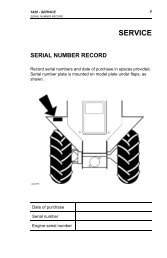
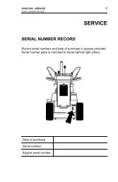
SERIAL NUMBERS<br />
Write frame and engine serial numbers, plus model numbers in<br />
"Owners Record" section below. Your dealer needs these<br />
numbers when you order parts. The serial number is located on<br />
a sticker on the center section of the frame.<br />
DIRECTIONS<br />
"Right Hand" and "Left Hand" sides of the sod cutter are<br />
determined by facing the back of the sod cutter as you would<br />
operate the machine.<br />
OWNER’S RECORD<br />
DATE PURCHASED _________________________________<br />
SOD CUTTER MODEL NUMBER______________________<br />
SOD CUTTER SERIAL NUMBER______________________<br />
ENGINE MODEL NUMBER __________________________<br />
ENGINE SERIAL NUMBER___________________________<br />
PRE-DELIVERY CHECK LIST<br />
Check the following before you deliver the sod cutter to the<br />
customer.<br />
1. Guards and shields fastened in place.<br />
2. Decals fastened and legible.<br />
3. Gas lever on engine turned on.<br />
4. All seven lubrication points greased.<br />
5. 2:1 gearbox oil level.<br />
6. Engine oil level.<br />
7. Air cleaner.<br />
8. Touch up scratches.<br />
9. Chain tight.<br />
10. Engine belt tight.<br />
11. Levers working properly.<br />
12. All controls.<br />
13. Add fuel, start engine, test run.<br />
DATE SET UP __________/__________/__________<br />
DELIVERY CHECK LIST<br />
Review the operators manual with the customer.<br />
Explain the following:<br />
1. <strong>Classen</strong> warranty.<br />
2. Safe operation and service.<br />
3. How to use controls.<br />
4. Operating the machine correctly.<br />
5. Transporting the sod cutter.<br />
6. Correct fuel and lubricants.<br />
7. Daily and periodic inspections.<br />
8. Changing oil after break-in period.<br />
9. Servicing the sod cutter regularly and correctly.<br />
10. <strong>Classen</strong> parts and service.<br />
11. Give the customer the operators manual and<br />
encourage customer to read it.<br />
DATE DELIVERED __________/__________/__________<br />
SIGNATURE _______________________________________<br />
1
2<br />
SAFETY<br />
HANDLE FUEL SAFELY - AVOID FIRES<br />
Handle gasoline with care; it is highly flammable. Use an<br />
approved gasoline container.<br />
Fill the fuel tank outdoors.<br />
DO NOT fill tank completely full.<br />
DO NOT smoke while you fill fuel tank.<br />
DO NOT remove gas cap if engine is running.<br />
READ SAFETY SIGNS<br />
Carefully read and follow all caution stickers.<br />
WARNING<br />
ALL GUARDS MUST BE IN PLACE<br />
WHILE MACHINE IS IN OPERATION<br />
WARNING<br />
KEEP HANDS & FEET AWAY<br />
FROM MOVING PARTS<br />
OPERATE SAFELY<br />
Carefully read this manual and operate sod cutter correctly.<br />
PROTECT CHILDREN<br />
Keep children and pets out of the area where you are cutting<br />
sod.<br />
AVOID TIPPING<br />
Make sure you do not get too close to sharp drop-offs to avoid<br />
tipping sod cutter over.<br />
OPERATE SAFELY ON SLOPES<br />
You may cut sod any direction on slopes, however, make sure<br />
you do this carefully. Cutting on slopes can be dangerous. To<br />
avoid any accidents, make sure to leave yourself room to<br />
correct the problem if one arises. Always park your sod cutter<br />
on level ground.<br />
PRACTICE SAFE MAINTENANCE<br />
Keep all machine parts in good condition and fastened in<br />
place. Fix damages immediately. Replace worn or broken<br />
parts. Whenever you work on the sod cutter, disconnect spark<br />
plug wire.<br />
START ENGINE SAFELY<br />
Make sure hands and feet are out of the way of moving parts<br />
when starting engine.<br />
ENGINE STARTING<br />
PROCEDURES<br />
NOTICE: There are two locations on this engine that require<br />
oil, both the crankcase and the transmission<br />
(gearbox). Running the engine or gearbox with a low<br />
oil level can cause engine damage. Refer to the<br />
engine manual for complete engine information<br />
and recommendations.<br />
ENGINE OIL LEVEL CHECK<br />
1. BEFORE CHECKING ENGINE:<br />
• make certain the engine is level<br />
• the engine switch is in the OFF position<br />
• the sod cutter blade is NOT engaged<br />
• the drive wheels are disengaged.<br />
2. Remove the filler cap/dipstick and wipe it clean.<br />
3. Insert and remove the dipstick without screwing it<br />
into the filler neck. Check the oil level shown on the<br />
dipstick.<br />
4. If the oil level is low, fill to the edge of the oil filler<br />
hole with the recommended oil. SAE 10W-30 is<br />
recommended for general use. Refer to engine oil<br />
recommendations in engine manual for other<br />
viscosities and information.<br />
5. Screw in the filler cap/dipstick securely.<br />
TRANSMISSION OIL LEVEL CHECK<br />
1. Check the transmission oil level with the engine<br />
stopped and in a level position.<br />
2. Remove the filler cap/dipstick and wipe it clean.<br />
3. Insert and remove the dipstick without screwing it<br />
into the filler hole. Check the oil level shown on the<br />
dipstick.<br />
4. If the oil level is low, add oil to reach the upper limit<br />
mark on the dipstick. Use the same oil that is<br />
recommended for the engine, SAE 10W-30.<br />
5. Screw in the filler cap/dipstick securely.<br />
HYDROSTATIC TRANSMISSION CHECK<br />
1. Check the hydrostatic transmission level with the<br />
engine stopped and in a level position.<br />
2. Visually inspect to see if level is low.<br />
3. If oil level is low, add oil to reach upper limit mark<br />
on reservoir.<br />
4. Use 20W 50 Oil.<br />
STARTING ENGINE<br />
1. Turn fuel cock to the "open" position.<br />
2. Turn choke on (closed).<br />
3. Turn ignition switch to "on".<br />
4. Move throttle lever on engine to half throttle position.<br />
5. Pull recoil starter rope until engine starts.<br />
6. After engine is warm, turn off choke (open).
7. Allow engine to run one minute before cutting sod.<br />
8. Check engine rpm setting before operating. DO NOT<br />
exceed 3600 rpm.<br />
STOPPING ENGINE<br />
1. Turn throttle to "slow" position.<br />
2. Turn off ignition switch.<br />
OPERATING THE<br />
SOD CUTTER<br />
PREPARATION<br />
1. Police lawn area for obstacles and debris (i.e.<br />
sprinklers, hoses, toys, etc.). Remove all items.<br />
2. Make sure underground sprinkler heads and other<br />
hidden obstacles are marked to prevent damage.<br />
3. Mark other areas where sod cutting will be a problem<br />
or too risky (i.e. mud, tree roots, steep hills).<br />
OPERATING<br />
1. Start the engine. CAUTION: To avoid injury, do not<br />
place your feet or other body parts under the blade<br />
while starting the engine.<br />
2. Push shifter handle into neutral position.<br />
3. Select the correct cutting depth desired up to 2 1/2<br />
inches. Loosen the tee handle from the depth gauge<br />
plate, located under the height adjustment bar, (#3 on<br />
illustration) and put it to the correct height setting.<br />
Tighten the tee handle.<br />
4. Raise the main handle upward so the front nose of the<br />
sod cutter rests on the ground.<br />
5. Loosen the 1/2" handle nut (#2 on illustration) and<br />
lower the height adjustment bar to rest on the depth<br />
gauge. Now tighten the 1/2" handle nut securely so it<br />
will not loosen with the vibration of the machine.<br />
6. Go to the back of the machine and lower the handle<br />
until the cutting blade rests on the ground. You are<br />
now ready to cut sod.<br />
7. Push shifter handle into sod cutting position.<br />
8. Pull the throttle to the desired operating speed<br />
(#6 on illustration). Maximum engine rpm is<br />
recommended for smooth operation.<br />
9. After cutting a short distance, stop machine by letting<br />
the twist grip throttle control go back to its original<br />
position. Check thickness of cut and adjust if necessary.<br />
10. At the end of each cutting pass, lift up on the handle<br />
bar to clear the cutting blade from the sod. Retard the<br />
throttle control and turn machine around into the<br />
position for the next cut.<br />
11. When finished cutting sod, reverse steps 6 through 3,<br />
leaving the wheel drive handle in transportation<br />
position.<br />
GENERAL MAINTENANCE<br />
To keep the sod cutter in good operating condition, perform<br />
the following:<br />
• Keep blade sharp; a sharp blade cuts cleaner, faster and<br />
more uniformly and places less load on the machine.<br />
Sharpen cutting edge on bevel or top side only.<br />
• Keep drive belt at proper tension and free of oil and<br />
dirt at all times.<br />
• Check engine oil level and air filter element daily.<br />
• Check for loose bolts and connections.<br />
• All grease fittings are pressurized type. Use a good<br />
grade Lithium Base Grease or equivalent. Grease<br />
eccentric arms sparingly every 4 hours of service, all<br />
others daily. Wipe off all grease fittings before and after<br />
each greasing (there are a total of 7 grease fittings).<br />
• To make sure the chain on the front drive wheels is<br />
tight, you will need to remove the chain guard to<br />
check this. If tightening is required, loosen nuts and<br />
bolts on the 3/4" pillow block bearings and push the<br />
bearings toward the back of the sod cutter until chain<br />
is tight. Make sure both bearings go back evenly to<br />
keep jackshaft running even with the frame. After<br />
doing this, retighten nuts and bolts on the bearing and<br />
replace the chain guard.<br />
• Engine (refer to Honda owner’s manual).<br />
• Check chain tension on chain on left side of<br />
hydrostatic unit. If this needs to be tightened, loosen<br />
bolt and nut on sprocket and move in slot to tighten<br />
chain and re-tighten bolt and nut.<br />
SAFETY WARNING<br />
DO NOT STORE GASOLINE (FUEL)<br />
UNNECESSARILY OVER LONG PERIODS OF<br />
TIME. TO PREVENT POSSIBLE EXPLOSION,<br />
STORE ONLY IN AN APPROVED "SAFE"<br />
CONTAINER. TO PREVENT EXPLOSION OF<br />
VAPORIZED FUEL, DO NOT STORE MACHINE<br />
WITH FUEL IN TANK OR CARBURETOR IN AN<br />
ENCLOSURE WITH OPEN FLAME.<br />
(EXAMPLE: FURNACE OR WATER HEATER<br />
PILOT LIGHT.)<br />
3
4<br />
TROUBLESHOOTING CHART<br />
PROBLEM CAUSE REMEDY<br />
Blade will not stay in ground a. Bottom of blade is rounded<br />
off<br />
Belts jump off a. Wrong type of belt<br />
b. Pulley misalignment<br />
a. Blade should be sharpened<br />
or replaced<br />
a. Use only the special factory<br />
belt<br />
b. Realign pulley<br />
NOTES:____________________________________________________________________________________________________<br />
___________________________________________________________________________________________________________<br />
___________________________________________________________________________________________________________<br />
___________________________________________________________________________________________________________<br />
___________________________________________________________________________________________________________<br />
___________________________________________________________________________________________________________
HYDRO-DRIVE SOD CUTTER<br />
PARTS MANUAL<br />
SCH-12/5.5 – S.N. 000101 & UP<br />
SCH-16/5.5 – S.N. 000101 & UP<br />
SCH-18/5.5 – S.N. 000101 & UP<br />
SCH-20/5.5 – S.N. 000101 & UP<br />
SCH-12/8.0 – S.N. 000101 & UP<br />
SCH-16/8.0 – S.N. 000101 & UP<br />
SCH-18/8.0 – S.N. 000101 & UP<br />
SCH-20/8.0 – S.N. 000101 & UP<br />
SCH-<strong>24</strong>/8.0 – S.N. 000101 & UP<br />
5
6<br />
HYDRO-DRIVE SOD CUTTER MAIN FRAME<br />
KEY PART NO. QTY/PER SHEET DESCRIPTION<br />
1 C400<strong>24</strong>6 1 SOD CUTTER FRAME<br />
2 C400<strong>24</strong>7 1 SMALL GUARD<br />
3 C500101 1 5/16" NUT<br />
4 C500115 8 5/16" LOCK WASHER<br />
5 C500140 7 5/16" X 3/4" BOLT<br />
6 C500083 1 5/16" FLAT WASHER<br />
7 C300002 1 AXLE PIN<br />
8 C100017 1 TIRE AND WHEEL ASSEMBLY, 9x350x4<br />
9 C500016 2 5/32" X 1-1/2" COTTER PIN<br />
10 C400<strong>24</strong>8 1 CHAIN GUARD<br />
11 C500219 1 5/16" X 5" BOLT<br />
12 C400234 1 LARGE GUARD<br />
13 C500130 6 3/8" LOCK WASHER<br />
14 C500129 5 3/8" NUT<br />
15 C100010 2 IDLER PULLEY<br />
16 C500042 7 3/8" FLAT WASHER<br />
17 C500091 2 3/8" X 2" BOLT<br />
18 C100021 2 BRASS BUSHING<br />
19 C500001 1 GREASE FITTING, 1/4"-28<br />
KEY PART NO. QTY/PER SHEET DESCRIPTION<br />
20 C400010 1 CLUTCH ARM<br />
21 C500043 2 3/8" X 1" BOLT<br />
22 C100074 1 DECAL, "CLASSEN"<br />
23 C100496 1 DECAL, "SCH-18"<br />
<strong>24</strong> C100069 1 DECAL, "DANGER"<br />
25 C100096 1 DECAL, "ALL GUARDS" (NOT SHOWN)<br />
26 C100489 1 DECAL “HYDRO-DRIVE “ (NOT SHOWN)<br />
27 C100501 1 3/8" VLIER PIN<br />
28 C400251 1 NETURAL HANDLE<br />
29 C100106 1 DECAL, SERIAL NUMBER (NOT SHOWN)<br />
30 C100073 1 LUBRICATION TAG (NOT SHOWN)<br />
31 C400237 1 BUMPER<br />
32 C400011 2 12" BLADE ADAPTOR<br />
33 C500133 12 5/16" X 1" BOLT<br />
34 C300133 2 16" BLADE ADAPTOR<br />
35 C500142 6 5/16" X 2" BOLT<br />
36 C300047 2 20" BLADE ADAPTOR<br />
37 C400188 2 <strong>24</strong>" BLADE ADAPTOR<br />
38 C100502 1 3/8” SNAP RING
KEY<br />
1<br />
1<br />
2<br />
3<br />
3<br />
4<br />
5<br />
6<br />
7<br />
8<br />
9<br />
10<br />
11<br />
12<br />
13<br />
14<br />
15<br />
16<br />
17<br />
18<br />
19<br />
20<br />
21<br />
22<br />
HYDRO-DRIVE SOD CUTTER POWER TRAIN ASSEMBLY<br />
PART NO.<br />
C100005<br />
C100114<br />
C100028<br />
C100491<br />
C100503<br />
C500011<br />
C200054<br />
C100492<br />
C500174<br />
C200044<br />
C500004<br />
C500130<br />
C500129<br />
C100513<br />
C500003<br />
C700002<br />
C100004<br />
C600003<br />
C500034<br />
C500006<br />
C500106<br />
C200002<br />
C500181<br />
C100043<br />
QTY/PER SHEET<br />
1<br />
1<br />
1<br />
1<br />
1<br />
1<br />
1<br />
1<br />
8<br />
1<br />
1<br />
4<br />
4<br />
1<br />
4<br />
2<br />
4<br />
1<br />
8<br />
16<br />
16<br />
1<br />
2<br />
1<br />
DESCRIPTION<br />
HONDA 5.5 HP ENGINE W/ DEFLECTOR<br />
HONDA 8.0 HP ENGINE W/ DEFLECTOR<br />
PULLY W/ HUB AND BOLTS, 4" X 22MM<br />
B55 V-BELT 5HP<br />
B58 V-BELT 8HP<br />
3/16" X 1-3/4" SQUARE KEY<br />
2BK62H SHEAVE AND 15MM HUB<br />
SPRING PLUNGER<br />
1/2" X 1-3/4" BOLTS<br />
13 TOOTH SPROCKET<br />
1/4" X 1" SQUARE KEY<br />
3/8" LOCK WASHER<br />
3/8" NUT<br />
B38 V-BELT<br />
1/4" X 7/8" HALF MOON KEY<br />
ECCENTRIC HUB<br />
1" PILLOW BLOCK WITH COLLAR<br />
ECCENTRIC SHAFT<br />
1/2" FLAT WASHER<br />
1/2" LOCK WASHER<br />
1/2" NUT<br />
6" PULLEY WITH 1" HUB<br />
1/4" X 1-1/2" SQUARE KEY<br />
IDLER SPROCKET<br />
KEY PART NO. QTY/PER SHEET DESCRIPTION<br />
23 C500147 4 5/16" X 1-1/2" BOLT<br />
<strong>24</strong> C100013 2 3/4" PILLOW BLOCK WITH COLLAR<br />
25 C500083 8 5/16" FLAT WASHER<br />
26 C500115 8 5/16" LOCK WASHER<br />
27 C500101 8 5/16" NUT<br />
28 C100493 1 #40 X 54 WELDED SPROCKET AND HUB<br />
29 C100495 1 #40 CHAIN X 50 ROLLER<br />
30 C100025 2 CHAIN CONNECTING LINK<br />
31 C500158 8 1/2" X 3-1/2" BOLT<br />
32 C7000<strong>24</strong> 4 DRIVE WHEEL (TWO WHEELS ON SC-12)<br />
33 C300001 1 DRIVE SHAFT SPACER<br />
34 C600004 1 DRIVE SHAFT<br />
35 C500136 2 1/4" NUT<br />
36 C500137 2 1/2" LOCK WASHER<br />
37 C100027 1 THROTTLE SPRING<br />
38 C500157 2 1/4" X 3-1/2" BOLT<br />
39 C500146 4 3/8" X 1-1/2" BOLT<br />
40 C200001 1 DRIVE SHAFT SPROCKET<br />
41 C100311 1 HYDRO-GEAR<br />
42 C500168 2 5/16 X 4-1/2 BOLT<br />
43 C500074 2 5/16 X 1-3/4 BOLT<br />
44 C100494 1 #40 CHAIN X 76 ROLLER<br />
45 C200056 1 #40X12X3/4 SPROCKET AND SHAFT<br />
7
8<br />
HYDRO-DRIVE SOD CUTTER HANDLE ASSEMBLY<br />
KEY PART NO. QTY/PER SHEET DESCRIPTION<br />
1 C100018 2 HANDLE GRIP<br />
2 C400<strong>24</strong>3 1 MAIN HANDLE<br />
3 C300138 1 HANDLE BRACE<br />
4 C500043 6 3/8" X 1" BOLT<br />
5 C100486 1 THUMB THROTTLE AND CABLE<br />
6 C500041 6 3/8" LOCK NUT<br />
7 C500118 1 1/4" X 1-3/4" BOLT<br />
8 C500136 1 1/4" NUT<br />
9 C500137 1 1/4" LOCK WASHER<br />
10 C100007 4 RUBBER GRIP<br />
11 C400008 1 HANDLE ENGAGEMENT<br />
12 C500019 1 SMALL HANDLE SPRING<br />
13 C500139 1 1/4" LOCK NUT<br />
14 C100029 1 12" CUTTING BLADE<br />
14 C100416 1 16" CUTTING BLADE<br />
14 C100016 1 18" CUTTING BLADE<br />
14 C100110 1 20" CUTTING BLADE<br />
14 C100329 1 <strong>24</strong>" CUTTING BLADE<br />
15 C500154 1 3/8" X 2-1/2" BOLT<br />
16 C500042 2 3/8" FLAT WASHER<br />
17 C400250 1 SHIFTER ARM<br />
18 C500025 2 3/8" FINE NUT<br />
19 C500026 3 3/8" CLEVIS YOKE<br />
20 C500134 3 3/8" X 1-1/4" BOLT<br />
21 C500146 1 3/8" X 1-1/2" BOLT<br />
22 C500133 7 5/16" X 1" BOLT<br />
23 C500101 8 5/16" NUT<br />
<strong>24</strong> C500115 7 5/16" LOCK WASHER<br />
25 C100134 1 DECAL, "WHEEL DRIVE" (NOT SHOWN)<br />
26 C500001 6 GREASE FITTING, 1/4"-28<br />
27 C400490 1 DECAL, “HYDRO MANUAL ROLL” (NOT SHOWN)<br />
KEY PART NO. QTY/PER SHEET DESCRIPTION<br />
28 C500130 6 3/8" LOCK WASHER<br />
29 C500129 7 3/8" NUT<br />
30 C400007 1 CUTTING BLADE ADJUSTMENT ARM<br />
31 C500007 1 1/2" HANDLE NUT<br />
32 C500006 3 1/2" LOCK WASHER<br />
33 500034 14 1/2" FLAT WASHER<br />
34 C400001 1 HEIGHT ADJUSTMENT BAR<br />
35 C400238 1 PITCH ADJUSTMENT BAR<br />
36 C300039 1 DEPTH GUAGE<br />
37 C400239 1 1/4" THREADED T-HANDLE<br />
38 C200005 1 HEIGHT ADJUSTMENT BOLT<br />
39 C200004 1 PITCH ADJUSTMENT BOLT<br />
40 C500106 7 1/2" NUT<br />
41 C500152 2 1/2" X 2-3/4" BOLT<br />
42 C500151 2 1/2" X 3" FINE BOLT<br />
43 C100001 12 3/4" NYLON WASHER<br />
44 C100002 12 SEAL<br />
45 C600001 6 STEEL SLEEVE<br />
46 C800001 2 ECCENTRIC ARM<br />
47 C100003 6 BEARING<br />
48 C800002 2 BLADE ARM<br />
49 C400488 1 DECAL, “HYDRO SPEED” (NOT SHOWN)<br />
50 C500<strong>24</strong>1 2 1/2" X 1" BOLT<br />
51 C500132 1 1/2" X 4" BOLT<br />
52 C500065 1 SPRING<br />
53 C400253 1 3/8" LINKAGE ARM<br />
54 C400<strong>24</strong>9 1 CLUTCH ARM<br />
55 C500<strong>24</strong>2 1 #10 X 3/4" SOCKET HEAD BOLT<br />
56 C100132 1 DECAL, "CUTTER BLADE" (NOT SHOWN)<br />
57 C100133 1 DECAL, "SLOW/FAST" (NOT SHOWN)
10<br />
Schiller Grounds Care, Inc.<br />
1028 Street Road • Southampton, PA 18966<br />
Telephone: 1-800-366-6268<br />
TWO YEAR LIMITED WARRANTY<br />
Effective April 1, 2007<br />
For the period of two years from the date of purchase, CLASSEN MFG., INC. will repair or replace for the original purchaser free<br />
of charge, any part or parts found upon the examination of our factory authorized service station, or by the factory in Norfolk,<br />
Nebraska, to be defective in material or workmanship. All transportation charges on parts submitted for repair or replacement under<br />
this warranty shall be borne by the purchaser.<br />
This warranty does not include engines or engine parts, tires, batteries, or gearboxes that are covered under separate warranties<br />
furnished by their manufacturer or supplier, nor does it include normal maintenance parts, including but not limited to, spark plugs,<br />
points, filters, blades, and lubricants.<br />
All service under this warranty will be furnished or performed by our factory authorized service stations.<br />
There is no other expressed warranty. Implied warranties, including those of merchantability and fitness for a particular purpose, are<br />
limited to two years from the date of purchase and to the extent permitted by law, any and all implied warranties are excluded. The<br />
above remedy of repair and replacement of defective parts is the purchaser’s exclusive remedy for any defect, malfunction or breach<br />
of warranty. Liability for incidental or consequential damages under any and all warranties is excluded to the extent permitted<br />
by law.<br />
NORMAL RESPONSIBILITIES OF THE SELLER AND THE USER<br />
1. The Distributor or Dealer is responsible for the proper assembly and preparation of the product for delivery to the end user.<br />
2. The User is responsible for reading the <strong>Manual</strong> and Instructions.<br />
3. The User is responsible for proper operation and maintenance as described in the manual.<br />
4. The User is responsible for the replacement of wear items such as blades, belts, tires, batteries, etc.<br />
5. The User is responsible for damage due to improper operation and maintenance, as well as abuse.<br />
All claims must be received by the factory 30 days after the end of the warranty period to receive warranty consideration.<br />
© 2009 Schiller Grounds Care, Inc. All Rights Reserved.<br />
07/10
GRACIAS<br />
INTRODUCCIÓN<br />
Gracias por comprar el cortador de tepe <strong>Classen</strong> modelo<br />
SCH-12, SCH-16, SCH-18, SCH-20 o SCH-<strong>24</strong>.<br />
LEA ESTE MANUAL<br />
Lea detenidamente este manual para aprender el<br />
funcionamiento correcto del cortador de tepe. De no hacer<br />
esto se pueden producir lesiones personales o daños en los<br />
equipos.<br />
Este manual debe considerarse parte permanente de su cortador<br />
de tepe y debe permanecer con el mismo si lo vende.<br />
GARANTÍA<br />
Consulte la última página.<br />
MEDICIONES<br />
En este manual se usan unidades de medida de EE.UU.<br />
NÚMEROS DE SERIE:<br />
Escriba los números de serie del bastidor y del motor, más los<br />
números de modelo en la sección de “Registro del propietario”.<br />
Su distribuidor necesita estos números al pedir piezas. El<br />
número de serie está ubicado en un adhesivo en la sección<br />
central del bastidor.<br />
INSTRUCCIONES<br />
Los lados “derecho” e “izquierdo” del cortador de tepe vienen<br />
determinados haciendo frente a la “parte trasera” de la<br />
máquina como si estuviera haciendo funcionar máquina.<br />
REGISTRO DEL PROPIETARIO<br />
FECHA DE COMPRA ________________________________<br />
N° DE MODELO DEL CORTADOR DE TEPE ____________<br />
N° DE SERIE DEL CORTADOR DE TEPE _______________<br />
NÚMERO DE MODELO DEL MOTOR__________________<br />
NÚMERO DE SERIE DEL MOTOR_____________________<br />
LISTA DE COMPROBACIÓN ANTERIOR A LA ENTREGA<br />
Compruebe lo siguiente antes de entregar el cortador de tepe al<br />
cliente.<br />
1. Protectores y pantallas sujetos en posición.<br />
2. Calcomanías sujetas y legibles.<br />
3. Palanca de gasolina del motor en la posición<br />
encendida.<br />
4. Los ocho puntos de lubricación engrasados.<br />
5. Nivel de aceite de la caja de engranajes 2:1<br />
6. Nivel de aceite del motor.<br />
7. Filtro de aire.<br />
8. Retoque las rayaduras.<br />
9. Cadena tensada.<br />
10. Correa del motor tensada.<br />
11. Palancas funcionando debidamente.<br />
12. Todos los controles.<br />
13. Añada combustible, arranque el motor, haga una<br />
prueba de funcionamiento.<br />
FECHA DE CONFIGURACIÓN _______/_______/_______<br />
LISTA DE COMPROBACIÓN DE ENTREGA<br />
Revise el manual del operador con el cliente.<br />
Explique lo siguiente:<br />
1. Garantía de <strong>Classen</strong>.<br />
2. Operación y servicio seguros.<br />
3. Cómo usar los controles.<br />
4. Funcionamiento correcto de la máquina.<br />
5. Transporte del cortador de tepe.<br />
6. Combustible y lubricantes correctos.<br />
7. Inspecciones diarias y periódicas.<br />
8. Cambio de aceite después del período de rodaje.<br />
9. Cómo efectuar el servicio del cortador de tepe de<br />
forma regular y correcta.<br />
10. Piezas y servicio de <strong>Classen</strong>.<br />
11. Dé el manual del operador al cliente y anímele a que<br />
lo lea.<br />
FECHA DE ENTREGA<br />
__________/__________/__________<br />
FIRMA ___________________________________________<br />
11
12<br />
SEGURIDAD<br />
MANIPULE EL COMBUSTIBLE CON<br />
CUIDADO – EVITE LOS INCENDIOS<br />
Manipule la gasolina con cuidado, ya que es muy inflamable.<br />
Use un recipiente de gasolina aprobado.<br />
Llene el depósito de combustible al aire libre.<br />
NO llene el depósito completamente.<br />
NO fume mientras llene el depósito de combustible.<br />
NO quite la tapa de la gasolina con el motor en<br />
funcionamiento.<br />
LEA LOS LETREROS DE SEGURIDAD<br />
Lea detenidamente y siga las instrucciones de todas las<br />
calcomanías de precaución.<br />
ADVERTENCIA<br />
LOS PROTECTORES DEBEN ESTAR EN POSICIÓN<br />
MIENTRAS LA MÁQUINA ESTÉ EN<br />
FUNCIONAMIENTO<br />
ADVERTENCIA<br />
NO ACERQUE LAS MANOS Y LOS PIES A LAS<br />
PIEZAS MÓVILES<br />
HAGA FUNCIONAR DE FORMA SEGURA<br />
Lea detenidamente este manual y haga funcionar el cortador de<br />
tepe correctamente.<br />
PROTEJA A LOS NIÑOS<br />
No deje que se acerquen los niños y los animales al área donde<br />
esté cortando tepe.<br />
EVITE LOS VUELCOS<br />
Asegúrese de no acercarse demasiado a los desniveles grandes<br />
para evitar que se vuelque el cortador de tepe.<br />
HAGA FUNCIONAR LA UNIDAD CON<br />
SEGURIDAD EN LAS PENDIENTES<br />
Puede cortar tepe en cualquier dirección en las pendientes, no<br />
obstante, asegúrese de hacerlo con cuidado. El corte en<br />
pendientes puede ser peligroso. Para evitar accidentes,<br />
asegúrese de dejarse sitio para corregir el problema en caso de<br />
que surja un problema. Estacione siempre el cortador de tepe<br />
sobre un terreno horizontal.<br />
PRACTIQUE EL MANTENIMIENTO SEGURO<br />
Mantenga todas las piezas de la máquina en buenas<br />
condiciones y sujetas en posición. Arregle los daños de<br />
inmediato. Reemplace las piezas desgastadas o rotas. Siempre<br />
que trabaje en el cortador de tepe, desconecte el cable de la<br />
bujía.<br />
ARRANQUE EL MOTOR DE FORMA<br />
SEGURA<br />
Asegúrese de no acercar las manos y los pies a las piezas<br />
móviles al arrancar el motor.<br />
PROCEDIMIENTOS DE<br />
ARRANQUE DEL MOTOR<br />
AVISO: Hay dos lugares en este motor que requieren aceite: el<br />
cárter y la transmisión (caja de engranajes).El<br />
funcionamiento del motor o de la caja de engranajes con<br />
un bajo nivel de aceite puede causar daños en el motor.<br />
Consulte el manual del motor para obtener información<br />
completa y recomendaciones del motor.<br />
COMPRUEBE EL NIVEL DE ACEITE DEL<br />
MOTOR<br />
1. asegúrese de que el motor esté horizontal<br />
• el interruptor del motor está en la posición APAGADA<br />
• la hoja del cortador de tepe NO esté conectada<br />
• las ruedas de impulsión estén desconectadas.<br />
2. Quite la tapa del tubo de llenado/varilla indicadora de<br />
nivel y límpiela.<br />
3. Introduzca y saque la varilla indicadora de nivel sin<br />
atornillarla en el cuello del tubo de llenado. Compruebe<br />
el nivel de aceite mostrado en la varilla indicadora.<br />
4. Si el nivel de aceite es bajo, llene hasta el borde del<br />
agujero de llenado de aceite con el aceite recomendado.<br />
Se recomienda aceite SAE 10W-30 para uso general.<br />
Consulte las recomendaciones de aceite del motor en el<br />
manual del motor para averiguar otras viscosidades e<br />
información.<br />
5. Atornille bien la tapa del tubo de llenado/varilla<br />
indicadora de nivel.<br />
COMPRUEBE EL NIVEL DE ACEITE DE LA<br />
TRANSMISIÓN<br />
1. Compruebe el nivel de aceite de la transmisión con el<br />
motor parado y en posición horizontal.<br />
2. Quite la tapa del tubo de llenado/varilla indicadora de<br />
nivel y límpiela.<br />
3. Introduzca y saque la varilla indicadora de nivel sin<br />
atornillarla en el agujero del tubo de llenado. Compruebe<br />
el nivel de aceite mostrado en la varilla indicadora.<br />
4. Si el nivel de aceite es bajo, eche aceite hasta alcanzar la<br />
marca del límite superior en la varilla indicadora de<br />
nivel. Use el mismo aceite que se recomienda para el<br />
motor SAE 10W-30.<br />
5. Atornille bien la tapa del tubo de llenado/varilla<br />
indicadora de nivel.<br />
COMPRUEBE LA TRANSMISIÓN HIDROSTÁTICA<br />
1. Compruebe el nivel de aceite de la transmisión<br />
hidrostática con el motor parado y en posición nivelada.<br />
2. Inspeccione visualmente si el nivel es bajo.<br />
3. Si el nivel de aceite es bajo, añada aceite hasta alcanzar la<br />
marca del límite del depósito.<br />
4. Use aceite 20W 50.<br />
ARRANQUE DEL MOTOR<br />
1. Gire la llave de paso de combustible a la posición<br />
“abierta”.<br />
2. Active el estrangulador (cerrado).<br />
3. Ponga el interruptor de arranque en “encendido”.<br />
4. Mueva la palanca del acelerador del motor a la posición<br />
semiabierta.<br />
5. Tire de la cuerda del motor de arranque hasta que<br />
arranque el motor.<br />
6. Desactive el estrangulador (abierto) después de que se<br />
haya calentado el motor.
7. Deje que funcione el motor durante un minuto antes de<br />
empezar a cortar tepe.<br />
8. Compruebe el ajuste de las rpm del motor antes de<br />
hacerlo funcionar. NO supere las 3600 rpm.<br />
PARADA DEL MOTOR<br />
1. Gire el acelerador a la posición “lenta”.<br />
2. Ponga el interruptor de arranque en apagado.<br />
OPERACIÓN DEL<br />
CORTADOR DE TEPE<br />
PREPARACIÓN<br />
1. Observe el área del césped para ver si hay obstáculos<br />
y objetos sueltos (por ejemplo, aspersores, mangueras,<br />
juguetes, etc). Quite todos los componentes.<br />
2. Asegúrese de que las cabezas de los aspersores<br />
subterráneos y otros obstáculos ocultos estén<br />
marcados para impedir daños.<br />
3. Marque otras áreas en que el corte de tepe pueda ser<br />
un problema o demasiado arriesgado (por ejemplo,<br />
barro, raíces de árboles, cuestas inclinadas).<br />
OPERACIÓN<br />
1. Arranque el motor. PRECAUCIÓN: Para evitar<br />
lesiones, no ponga los pies ni ninguna otra parte del<br />
cuerpo debajo de las hojas al arrancar el motor.<br />
2. Empuje la palanca de cambio a la posición neutra.<br />
3. Seleccione la profundidad de corte correcta deseada<br />
hasta 2 1/2”. Afloje el asa en te de la placa del calibre<br />
de profundidad, ubicada debajo de la barra de ajuste<br />
de altura, (N° 3 de la ilustración) y póngalo en el<br />
ajuste de altura correcto. Apriete el asa en T.<br />
4. Suba el manillar principal de modo que la punta<br />
delantera del cortador de tepe quede apoyada sobre el<br />
terreno.<br />
5. Afloje la tuerca del manillar de 1/2” (N° 2 en la<br />
ilustración) y baje la barra de ajuste de altura para que<br />
se apoye en el calibre de profundidad. Apriete bien<br />
ahora la tuerca del manillar de 1/2” de modo que no<br />
se afloje con las vibraciones de la máquina.<br />
6. Vaya a la parte trasera de la máquina y baje el<br />
manillar hasta que la hoja de corte quede apoyada en<br />
el terreno. Ahora estará listo para cortar tepe.<br />
7. Empuje la palanca de cambio a la posición de corte.<br />
8. Jale el acelerador hasta la velocidad de operación<br />
deseada (N.º 6 en la ilustración). Se recomiendan rpm<br />
máximas del motor para lograr una operación<br />
uniforme.<br />
9. Después de cortar una pequeña distancia, pare la<br />
máquina dejando que el control de giro del acelerador<br />
vuelva a su posición original. Compruebe el espesor<br />
del corte y ajústelo si es necesario.<br />
10. Al final de cada pasada de corte, levante la barra del<br />
manillar para sacar la hoja de corte del tepe. Retrase<br />
el control del acelerador y dé la vuelta a la máquina<br />
para colocarla para el próximo corte.<br />
11. Cuando haya terminado de cortar el tepe, invierta los<br />
pasos 6 a 3, dejando el manillar de transmisión de las<br />
ruedas en la posición de transporte.<br />
MANTENIMIENTO GENERAL<br />
Realice lo siguiente para mantener el cortador de tepe en<br />
buenas condiciones de operación:<br />
• Mantenga la hoja afilada; una hoja afilada produce<br />
cortes más limpios, más rápidos y de manera más<br />
uniforme y somete a la máquina a menos carga. Afile<br />
la cuchilla por el lado biselado o lado superior<br />
solamente.<br />
• Mantenga la correa de impulsión a la tensión<br />
adecuada y sin aceite ni suciedad en todo momento.<br />
• Compruebe a diario el nivel de aceite del motor y el<br />
elemento del filtro de aire.<br />
• Compruebe si hay pernos y conexiones sueltos.<br />
• Todas las graseras son del tipo a presión. Use una<br />
buena grasa a base de litio o equivalente. Engrase<br />
ligeramente los brazos excéntricos cada 4 horas de<br />
servicio y los demás a diario. Limpie las graseras<br />
antes y después de engrasarlas (hay un total de 8<br />
graseras).<br />
• Para asegurarse de que esté ajustada la cadena de las<br />
ruedas de impulsión delanteras, tendrá que quitar el<br />
protector de la cadena para comprobarlo. Si es<br />
necesario tensar, afloje las tuercas y los pernos de las<br />
chumaceras de 3/4” y empuje éstas hacia la parte<br />
trasera del cortador de tepe hasta que se tense la<br />
cadena. Asegúrese de que ambas chumaceras lleguen<br />
hasta el fondo por igual para que el eje intermedio<br />
funcione de modo uniforme con el bastidor. Después<br />
de hacer esto, vuelva a apretar las tuercas y los pernos<br />
en la chumacera y vuelva a colocar el protector de la<br />
cadena.<br />
• Motor (consulte el manual del propietario de Honda).<br />
• Compruebe la tensión de la cadena del lado izquierdo<br />
de la unidad hidrostática. Si necesita tensionarla,<br />
afloje el perno y la tuerca de la rueda de cadena y<br />
coloque la cadena en la ranura para tensionarla, luego<br />
vuelva a apretar el perno y la tuerca.<br />
ADVERTENCIA DE SEGURIDAD<br />
NO GUARDE LA GASOLINA (COMBUSTIBLE) DE<br />
FORMA INNECESARIA DURANTE PERÍODOS<br />
LARGOS PARA IMPEDIR UNA POSIBLE<br />
EXPLOSIÓN, GUARDE SOLAMENTE EN UN<br />
RECIPIENTE APROBADO “SEGURO”. PARA<br />
IMPEDIR LA EXPLOSIÓN DE COMBUSTIBLE<br />
VAPORIZADO, NO GUARDE LA MÁQUINA CON<br />
COMBUSTIBLE EN EL DEPÓSITO O EN EL<br />
CARBURADOR EN UN RECINTO CON UNA<br />
LLAMA ABIERTA. (EJEMPLO: LUZ PILOTO DE<br />
UNA CALDERA O UN CALENTADOR DE AGUA).<br />
13
14<br />
VÁLVULA DE<br />
DERIVACIÓN<br />
PROBLEMA CAUSA SOLUCIÓN<br />
La hoja no permanece en el<br />
terreno<br />
CONTROL DEL ACELERADOR DE<br />
DEDO<br />
MANILLAR DE TRACCIÓN<br />
DE LA RUEDA<br />
MANILLAR DE<br />
LA HOJA DE<br />
CORTE<br />
a. La parte inferior de la hoja<br />
está redondeada<br />
Las correas saltan y se salen a. Tipo de correa equivocado<br />
b. Polea desalineada<br />
TUERCA DEL MANILLAR<br />
PERNO DE AJUSTE DE ALTURA<br />
CUADRO DE LOCALIZACIÓN Y RESOLUCIÓN DE<br />
PROBLEMAS<br />
BARRA DE AJUSTE DE ALTURA<br />
a. La hoja debe afilarse o<br />
reemplazarse<br />
a. Use solamente la correa de<br />
fábrica especial<br />
b. Vuelva a alinear la polea<br />
NOTAS:____________________________________________________________________________________________________<br />
___________________________________________________________________________________________________________<br />
___________________________________________________________________________________________________________<br />
___________________________________________________________________________________________________________<br />
___________________________________________________________________________________________________________<br />
___________________________________________________________________________________________________________
MANUAL DE PIEZAS DE LA<br />
CORTADORA DE TEPE<br />
TRANSMISIÓN<br />
HIDROSTÁTICA<br />
SCH-12/5.5 – N/S 000101 y sig.<br />
SCH-16/5.5 – N/S 000101 y sig.<br />
SCH-18/5.5 – N/S 000101 y sig.<br />
SCH-20/5.5 – N/S 000101 y sig.<br />
SCH-12/8.0 – N/S 000101 y sig.<br />
SCH-16/8.0 – N/S 000101 y sig.<br />
SCH-18/8.0 – N/S 000101 y sig.<br />
SCH-20/8.0 – N/S 000101 y sig.<br />
SCH-<strong>24</strong>/8.0 – N/S 000101 y sig.<br />
15
16<br />
BASTIDOR PRINCIPAL DE LA CORTADORA DE TEPE TRANSMISIÓN HIDROSTÁTICA<br />
N.° N.° DE PIEZA. CANT./POR HOJA DESCRIPCIÓN<br />
1 C400<strong>24</strong>6 1 BASTIDOR DEL CORTADOR DE TEPE<br />
2 C400<strong>24</strong>7 1 PROTECTOR PEQUEÑO<br />
3 C500101 1 TUERCA DE 5/16”<br />
4 C500115 8 ARANDELA DE TRABA DE 5/16”<br />
5 C500140 7 PERNO DE 5/16” x 3/4”<br />
6 C500083 1 ARANDELA PLANA DE 5/16”<br />
7 C300002 1 PASADOR DE EJE<br />
8 C100017 1 CONJUNTO DE NEUMÁTICO Y RUEDA DE 9 x 350 x 4<br />
9 C500016 2 PASADOR DE ALETA DE 5/32” X 1 1/2”<br />
10 C400<strong>24</strong>8 1 PROTECTOR DE CADENA<br />
11 C500219 1 PERNO DE 5/16” X 5”<br />
12 C400234 1 PROTECTOR GRANDE<br />
13 C500130 6 ARANDELA DE TRABA DE 3/8”<br />
14 C500129 5 TUERCA DE 3/8”<br />
15 C100010 2 POLEA LOCA<br />
16 C500042 7 ARANDELA PLANA DE 3/8”<br />
17 C500091 2 PERNO DE 3/8” X 2”<br />
18 C100021 2 MANGUITO DE LATÓN<br />
19 C500001 1 GRASERA DE 1/4”-28<br />
N.° N.° DE PIEZA CANT./POR HOJA DESCRIPCIÓN<br />
20 C400010 1 BRAZO DEL EMBRAGUE<br />
21 C500043 2 PERNO DE 3/8” X 1”<br />
22 C100074 1 CALCOMANÍA “CLASSEN”<br />
23 C100496 1 CALCOMANÍA “SC-18”<br />
<strong>24</strong> C100069 1 CALCOMANÍA DE “PELIGRO”<br />
25 C100096 1 CALCOMANÍA DE “TODOS LOS PROTECTORES” (NO SE MUESTRA)<br />
26 C100489 1 CALCOMANÍA DE “TRANSMISIÓN HIDROSTÁTICA” (NO SE MUESTRA)<br />
27 C100501 1 PERNO VLIER DE 3/8"<br />
28 C400251 1 PALANCA DE NEUTRAL<br />
29 C100106 1 CALCOMANÍA DE “NÚMERO DE SERIE” (NO SE MUESTRA)<br />
30 C100073 1 ETIQUETA DE LUBRICACIÓN (NO SE MUESTRA)<br />
31 C400237 1 PARACHOQUES<br />
32 C400011 2 ADAPTADOR DE HOJA DE 12”<br />
33 C500133 12 PERNO DE 5/16” X 1”<br />
34 C300133 2 ADAPTADOR DE HOJA DE 16”<br />
35 C500142 6 PERNO DE 5/16” X 2”<br />
36 C300047 2 ADAPTADOR DE HOJA DE 20”<br />
37 C400188 2 ADAPTADOR DE HOJA DE <strong>24</strong>”<br />
38 C100502 1 ANILLO DE RESORTE DE 3/8”
N.°<br />
1<br />
1<br />
2<br />
3<br />
3<br />
4<br />
5<br />
6<br />
7<br />
8<br />
9<br />
10<br />
11<br />
12<br />
13<br />
14<br />
15<br />
16<br />
17<br />
18<br />
19<br />
20<br />
21<br />
22<br />
N.° DE PIEZA<br />
C100005<br />
C100114<br />
C100028<br />
C100491<br />
C100503<br />
C500011<br />
C200054<br />
C100492<br />
C500174<br />
C200044<br />
C500004<br />
C500130<br />
C500129<br />
C100513<br />
C500003<br />
C700002<br />
C100004<br />
C600003<br />
C500034<br />
C500006<br />
C500106<br />
C200002<br />
C500181<br />
C100043<br />
CANT./POR HOJA<br />
1<br />
1<br />
1<br />
1<br />
1<br />
1<br />
1<br />
1<br />
8<br />
1<br />
1<br />
4<br />
4<br />
1<br />
4<br />
2<br />
4<br />
1<br />
8<br />
16<br />
16<br />
1<br />
2<br />
1<br />
CONJUNTO DEL TREN DE FUERZA DEL CORTADOR<br />
DE TEPE DE TRANSMISIÓN HIDROSTÁTICA<br />
DESCRIPCIÓN<br />
MOTOR HONDA DE 5.5 HP CON DEFLECTOR<br />
MOTOR HONDA DE 8.0 HP CON DEFLECTOR<br />
POLEA CON CUBO Y PERNOS DE 4” x 22 mm<br />
CORREA TRAPECIAL B55 - 5 HP<br />
CORREA TRAPECIAL B58 - 8 HP<br />
CHAVETA CUADRADA DE 3/16” x 1 3/4”<br />
RUEDA DE POLEA 2BK62H Y CUBO DE 15MM<br />
ÉMBOLO DEL MUELLE<br />
PERNOS DE 12 x 1 -3/4”<br />
RUEDA DENTADA DE 13 DIENTES<br />
CHAVETA CUADRADA DE 1/4” X 1”<br />
ARANDELA DE TRABA DE 3/8”<br />
TUERCA DE 3/8”<br />
CORREA TRAPECIAL B38<br />
CHAVETA DE MEDIA LUNA DE 1/4” x 7/8”<br />
CUBO EXCÉNTRICO<br />
CHUMACERA DE 1” CON COLLAR<br />
EJE EXCÉNTRICO<br />
ARANDELA PLANA DE 1/2”<br />
ARANDELA DE TRABA DE 1/2”<br />
TUERCA DE 1/2”<br />
POLEA DE 6” CON CUBO DE 1”<br />
CHAVETA CUADRADA DE 1/4” x 1 1/2”<br />
RUEDA DENTADA LOCA<br />
N.° N.° DE PIEZA CANT./POR HOJA DESCRIPCIÓN<br />
23 C500147 4 PERNO DE 5/16” x 1 1/2”<br />
<strong>24</strong> C100013 2 CHUMACERA DE 3/4” CON COLLAR<br />
25 C500083 8 ARANDELA PLANA DE 5/16”<br />
26 C500115 8 ARANDELA DE TRABA DE 5/16”<br />
27 C500101 8 TUERCA DE 5/16”<br />
28 C100493 1 RUEDA DENTADA #40 X 54 SOLDADA Y CUBO<br />
29 C100495 1 CADENA N.º 40 X RODILLO DE 50<br />
30 C100025 2 ESLABÓN DE CONEXIÓN CON LA CADENA<br />
31 C500158 8 PERNO DE 1/2” x 3 1/2”<br />
32 C7000<strong>24</strong> 4 RUEDA DE TRACCIÓN (2 RUEDAS EN SC-12)<br />
33 C300001 1 ESPACIADOR DEL EJE DE IMPULSIÓN<br />
34 C600004 1 EJE DE IMPULSIÓN<br />
35 C500136 2 TUERCA DE 1/4”<br />
36 C500137 2 ARANDELA DE TRABA DE 1/2”<br />
37 C100027 1 RESORTE DEL ACELERADOR<br />
38 C500157 2 PERNO DE 1/4” x 3 1/2”<br />
39 C500146 4 PERNO DE 3/8” x 1 1/2”<br />
40 C200001 1 RUEDA DENTADA DEL EJE DE TRACCIÓN<br />
41 C100311 1 MECANISMO HIDROSTÁTICO<br />
42 C500168 2 PERNO DE 5/16 X 4 1/2”<br />
43 C500074 2 PERNO DE 5/16 X 1 3/4”<br />
44 C100494 1 CADENA N.º 40 X RODILLO DE 76<br />
45 C200056 1 RUEDA DENTADA Y EJE #40X12X3/4<br />
17
18<br />
CONJUNTO DEL MANILLAR DEL CORTADOR DE TEPE<br />
DE TRANSMISIÓN HIDROSTÁTICA<br />
N.° N.° DE PIEZA CANT./POR HOJA DESCRIPCIÓN<br />
1 C100018 2 ASIDEROS DEL MANILLAR<br />
2 C400<strong>24</strong>3 1 MANILLAR PRINCIPAL<br />
3 C300138 1 TIRANTE DEL MANILLAR<br />
4 C500043 6 PERNO DE 3/8” X 1”<br />
5 C100486 1 ACELERADOR DE DEDO Y CABLE<br />
6 C500041 6 TUERCA DE TRABA DE 3/8”<br />
7 C500118 1 PERNO DE 1/4” x 1 3/4”<br />
8 C500136 1 TUERCA DE 1/4”<br />
9 C500137 1 ARANDELA DE TRABA DE 1/4”<br />
10 C100007 4 ASIDERO DE CAUCHO<br />
11 C400008 1 ACCIONADOR DEL MANILLAR<br />
12 C500019 1 RESORTE DE MANILLAR PEQUEÑO<br />
13 C500139 1 TUERCA DE TRABA DE 1/4”<br />
14 C100029 1 HOJA DE CORTE DE 12”<br />
14 C100416 1 HOJA DE CORTE DE 16”<br />
14 C100016 1 HOJA DE CORTE DE 18”<br />
14 C100110 1 HOJA DE CORTE DE 20”<br />
14 C100329 1 HOJA DE CORTE DE <strong>24</strong>”<br />
15 C500154 1 PERNO DE 3/8” x 2 1/2”<br />
16 C500042 2 ARANDELA PLANA DE 3/8”<br />
17 C400250 1 BRAZO DEL CAMBIADOR<br />
18 C500025 2 TUERCA FINA DE 3/8”<br />
19 C500026 3 HORQUILLA DE 3/8”<br />
20 C500134 3 PERNO DE 3/8” x 1 1/4”<br />
21 C500146 1 PERNO DE 3/8” x 1 1/2”<br />
22 C500133 7 PERNO DE 5/16” X 1”<br />
23 C500101 8 TUERCA DE 5/16”<br />
<strong>24</strong> C500115 7 ARANDELA DE TRABA DE 5/16”<br />
25 C100134 1 CALCOMANÍA DE “TRACCIÓN EN LAS RUEDAS” (NO SE MUESTRA)<br />
26 C500001 6 GRASERA DE 1/4-28<br />
27 C400490 1 CALCOMANÍA DE “RODILLO HIDROSTÁTICO MANUAL” (NO SE<br />
N.° N.° DE PIEZA CANT./POR HOJA DESCRIPCIÓN<br />
28 C500130 6 ARANDELA DE TRABA DE 3/8”<br />
29 C500129 7 TUERCA DE 3/8”<br />
30 C400007 1 BRAZO DE AJUSTE DE LA HOJA DE CORTE<br />
31 C500007 1 TUERCA DE MANILLAR DE 1/2”<br />
32 C500006 3 ARANDELA DE TRABA DE 1/2”<br />
33 500034 14 ARANDELA PLANA DE 1/2”<br />
34 C400001 1 BARRA DE AJUSTE DE ALTURA<br />
35 C400238 1 BARRA DE AJUSTE DE INCLINACIÓN<br />
36 C300039 1 MEDIDOR DE PROFUNDIDAD<br />
37 C400239 1 ASA EN T ROSCADA DE 1/4”<br />
38 C200005 1 PERNO DE AJUSTE DE ALTURA<br />
39 C200004 1 PERNO DE AJUSTE DE INCLINACIÓN<br />
40 C500106 7 TUERCA DE 1/2”<br />
41 C500152 2 PERNO DE 1/2” x 2 3/4”<br />
42 C500151 2 PERNO FINO DE 1/2” x 3”<br />
43 C100001 12 ARANDELA DE NILÓN DE 3/4”<br />
44 C100002 12 SELLO<br />
45 C600001 6 MANGUITO DE ACERO<br />
46 C800001 2 BRAZO EXCÉNTRICO<br />
47 C100003 6 COJINETE<br />
48 C800002 2 BRAZO DE LA HOJA<br />
49 C400488 1 CALCOMANÍA DE “TRANSMISSIÓN HIDROSTÁTICA” (NO SE MUESTRA)<br />
50 C500<strong>24</strong>1 2 PERNO DE 1/2” X 1”<br />
51 C500132 1 PERNO DE 1/2” X 4”<br />
52 C500065 1 RESORTE<br />
53 C400253 1 BRAZO DE ARTICULACIÓN DE 3/8”<br />
54 C400<strong>24</strong>9 1 BRAZO DEL EMBRAGUE<br />
55 C500<strong>24</strong>2 1 PERNO CON CABEZA DE DADO #10 X 3/4"<br />
56 C100132 1 CALCOMANÍA “HOJA DE CORTE” (NO SE MUESTRA)<br />
57 C100133 1 CALCOMANÍA “LENTO/RÁPIDO” (NO SE MUESTRA)
NOTA: AL INSTALAR LOS<br />
SELLOS ASEGÚRESE DE QUE<br />
EL LADO DEL RESORTE<br />
QUEDE ALEJADO DEL<br />
COJINETE.<br />
19
Schiller Grounds Care, Inc.<br />
1028 Street Road • Southampton, PA 18966<br />
Teléfono: + (877) 596 6337<br />
DOS AÑOS DE GARANTÍA LIMITADA<br />
En vigor el 1 de abril de 2007<br />
Durante el período de dos años contado a partir de la fecha de compra, CLASSEN MFG., INC. reparará o reemplazará al comprador<br />
original de forma gratuita, cualquier pieza o piezas que después de examinarlas en nuestra estación de servicio autorizada de nuestra<br />
fábrica, o en la fábrica de Norfolk, Nebraska, tenga defectos de materiales o fabricación. Los costos de transporte de las piezas<br />
enviadas para su reparación o reemplazo, según los términos de esta garantía, deberán correr a costa del comprador.<br />
Esta garantía no incluye los motores o piezas de motor, neumáticos, baterías o cajas de engranajes cubiertos por garantías separadas<br />
suministradas por su fabricante o proveedor, ni incluye las piezas de mantenimiento normales, incluidas bujías, puntas, filtros, hojas<br />
y lubricantes, pero sin limitarse a éstas.<br />
Todos el servicio según esta garantía será suministrado o efectuado por nuestras estaciones de servicio autorizadas de fábrica.<br />
No existe ninguna otra garantía explícita. Las garantías implícitas, incluidas las de comerciabilidad e idoneidad para un cierto fin,<br />
están limitadas a dos años contado a partir de la fecha de compra en la medida que lo permita la ley, se excluyen todas y cada una de<br />
las garantías implícitas. El remedio anterior de reparación y reemplazo de piezas defectuosas es el remedio exclusivo por cualquier<br />
defecto, funcionamiento defectuoso o violación de garantía. En la medida que lo permita la ley, se excluye la responsabilidad por<br />
daños emergentes o concomitantes según cualquiera y todas las garantías.<br />
RESPONSABILIDADES NORMALES DEL VENDEDOR Y DEL USUARIO<br />
1. El distribuidor o el concesionario es responsable del montaje y de la preparación apropiados del producto para su entrega al<br />
usuario final.<br />
2. El usuario es responsable de leer el manual de instrucciones.<br />
3. El usuario es responsable de la operación y el mantenimiento apropiados según se describe en el manual<br />
4. El usuario es responsable de reemplazar los artículos que se desgasten como hojas, correas, neumáticos, baterías, etc.<br />
5. El usuario es responsable de los daños debidos al funcionamiento y al mantenimiento indebidos, así como a los abusos.<br />
Todas las reclamaciones deben ser recibidas por la fábrica 30 días después del final del período de garantía para que sean<br />
consideradas según la garantía.<br />
© 2010 Schiller Grounds Care, Inc. Todos los derechos reservados.<br />
07/10