Operator Manual Aerator - Ben's Rental and Sales
Operator Manual Aerator - Ben's Rental and Sales
Operator Manual Aerator - Ben's Rental and Sales

Create successful ePaper yourself
Turn your PDF publications into a flip-book with our unique Google optimized e-Paper software.
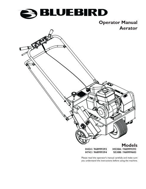
<strong>Operator</strong> <strong>Manual</strong><br />
<strong>Aerator</strong><br />
Models<br />
H424 / 968999392 H530A / 968999393<br />
H742 / 968999394 S530B / 968999683<br />
Please read the operator’s manual carefully <strong>and</strong> make sure<br />
you underst<strong>and</strong> the instructions before using the machine.
WARNING<br />
Engine exhaust, some of its constituents,<br />
<strong>and</strong> certain vehicle components contain<br />
or emit chemicals known to the State of<br />
California to cause cancer <strong>and</strong> birth defects<br />
or other reproductive harm.<br />
©2009 HTC. All rights reserved.<br />
Beatrice, NE. Printed in U.S.A.
INTRODUCTION ......................................................4<br />
Use .....................................................................4<br />
Good Service .....................................................4<br />
Serial Number ....................................................4<br />
SYMBOLS AND DECALS .........................................5<br />
SAFETY ....................................................................7<br />
General Information ...........................................7<br />
Safety Procedures ..............................................7<br />
General Use .......................................................8<br />
Preparations .......................................................9<br />
Operating .........................................................10<br />
Movement/Transport ........................................11<br />
Storage ............................................................11<br />
Children ............................................................11<br />
Fuel System .....................................................12<br />
Maintenance ....................................................13<br />
ASSEMBLY .............................................................14<br />
Models 424 <strong>and</strong> 530 H<strong>and</strong>les ..........................14<br />
Model 742 H<strong>and</strong>le ...........................................15<br />
Clutch <strong>and</strong> Throttle Cables ..............................16<br />
OPERATION ...........................................................17<br />
Aeration Tips ....................................................17<br />
Before You Start ...............................................17<br />
Rear Wheel Adjustment ...................................18<br />
Turning And Maneuvering ................................18<br />
Operating On Slopes .......................................19<br />
Aerating ...........................................................20<br />
Transporting .....................................................21<br />
Contents<br />
MAINTENANCE AND SERVICE .............................22<br />
Cleaning ...........................................................22<br />
Two Minute Rule ...............................................22<br />
Drive Train ........................................................23<br />
Engine ..............................................................23<br />
Clutch Cable ...................................................24<br />
Throttle Cable ..................................................24<br />
Chain ...............................................................26<br />
Removal <strong>and</strong> Replacement .............................26<br />
Adjusting Tension .............................................26<br />
Tines ................................................................27<br />
Tine Wear .........................................................27<br />
Tine Replacement ............................................27<br />
H<strong>and</strong>le .............................................................28<br />
Wheels .............................................................29<br />
Drive Wheel Shaft ...........................................29<br />
Rear Wheels .....................................................30<br />
TECHNICAL DATA .................................................31<br />
Torque Specifications .......................................35<br />
WARRANTY ............................................................36
Congratulations<br />
Thank you for purchasing a BlueBird lawn care<br />
product. Through your confidence in us, you have<br />
chosen an exceptionally high quality product.<br />
This manual is a valuable document. It describes your<br />
new BlueBird machine. Read the manual carefully<br />
before attempting to use the machine. Following the<br />
instructions (use, service, maintenance, etc.) can<br />
considerably increase the lifespan of your machine<br />
<strong>and</strong> even increase its resale value. Please contact<br />
your dealer for more information.<br />
If you sell your BlueBird machine, make sure to give<br />
the operator’s manual to the new owner.<br />
Use<br />
The dethatcher is used to remove the layer of<br />
thatch <strong>and</strong> surface-treat lawns, for example, powerraking,<br />
de-mossing <strong>and</strong> collecting thatch in the form<br />
of old grass or moss. With an attachment, it can<br />
also be used for seeding, both in initial sowing or<br />
overseeding.<br />
This <strong>Operator</strong>’s <strong>Manual</strong> belongs to machine<br />
with serial number:<br />
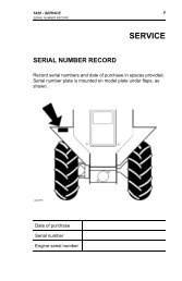
Serial Number<br />
The machine’s serial number can be found on the<br />
printed plate attached to the rear side panel of the<br />
machine. The plate includes the following information:<br />
• The machine’s type designation (MODEL).<br />
• The machine’s serial number (S/N).<br />
Please state the type designation <strong>and</strong> serial number<br />
when ordering spare parts.<br />
4 - BLUEBIRD<br />
IntRoDUCtIon<br />
Insure Your Machine<br />
Contact your insurance company to check on<br />
insurance coverage for your new machine. You should<br />
have all-inclusive insurance for liability, fire, damage<br />
<strong>and</strong> theft.<br />
Good Service<br />
BlueBird’s products are available only in specialized<br />
retail trades with complete service. This ensures<br />
that you as a customer get only the best support<br />
<strong>and</strong> service. Before the machine was delivered it<br />
underwent inspection <strong>and</strong> was adjusted by your<br />
dealer. When you need spare parts or support in<br />
service questions, guarantee issues, etc., please<br />
consult the following professional:<br />
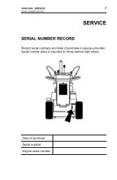
Engine<br />
number:<br />
The engine’s serial number is punched into the<br />
crankcase above the oil drainage screw.<br />
The engine type is specified on the crankcase under<br />
the air filter but also appears on the decal on the<br />
starter.<br />
Please state engine serial number <strong>and</strong> type when<br />
ordering replacement engine parts.
WARNING!<br />
Xxxx xxx xxxx xx xxxx x xxxx.<br />
Used in this publication to notify the reader of a risk<br />
of personal injury, particularly if the reader should<br />
neglect to follow instructions given in the manual.<br />
Decals<br />
1.<br />
2.<br />
3.<br />
4.<br />
1<br />
2<br />
DANGER watch your feet<br />
Warning for carbon monoxide<br />
Chain tension<br />
Safety warnings<br />
sYMBoLs AnD DeCALs<br />
1<br />
2<br />
530 Models<br />
4<br />
3<br />
IMPORTANT INFORMATION<br />
Xxxx xxx xxxx xx xxxx x xxxx.<br />
Used in this publication to notify the reader of a risk<br />
of material damage, particularly if the reader should<br />
neglect to follow instructions given in the manual.<br />
Used also when there is a potential for misuse or<br />
misassembly.<br />
5.<br />
6.<br />
7.<br />
2<br />
3<br />
4<br />
Barbells<br />
Removable wheel<br />
Controls<br />
424 & 742 Models<br />
2<br />
1<br />
540200122<br />
7<br />
3<br />
6<br />
5<br />
BLUEBIRD-5
1.<br />
2.<br />
3.<br />
4.<br />
6 - BLUEBIRD<br />
7<br />
DANGER watch your feet<br />
Warning for carbon monoxide<br />
Chain tension<br />
Safety warnings<br />
sYMBoLs AnD DeCALs<br />
6<br />
5<br />
4<br />
5.<br />
6.<br />
7.<br />
1<br />
Barbells<br />
Removable wheel<br />
Controls<br />
3<br />
2
General Information<br />
This manual will assist you in the safe operation <strong>and</strong><br />
proper maintenance of your BlueBird equipment.<br />
Read it thoroughly before attempting to operate the<br />
machine. Call your dealer or BlueBird if additional<br />
information is required.<br />
This equipment should not be modified without the<br />
manufacturer’s prior written authorization. Doing so<br />
may not only affect the equipment’s performance<br />
<strong>and</strong> durability, but also create safety hazards for the<br />
operator <strong>and</strong> the surroundings. Warranty will be void<br />
if changes are made to the equipment without the<br />
manufacturer’s prior written authorization.<br />
sAFetY<br />
Safety Procedures<br />
DO:<br />
• Read all maintenance <strong>and</strong> service instructions<br />
before attempting work.<br />
• Read engine manufacturer’s operating <strong>and</strong><br />
maintenance instructions.<br />
• Remove spark plug wire before commencing<br />
service.<br />
• Inspect lawn to be aerated <strong>and</strong> remove rocks,<br />
wire, string <strong>and</strong> other objects that might present a<br />
hazard before starting.<br />
• Identify <strong>and</strong> mark all ground objects to be<br />
avoided, such as sprinkler heads, stakes, water<br />
valves, clothes line anchors, etc.<br />
• Use machine for lawn aeration only.<br />
• Keep unsupervised children away from the<br />
equipment.<br />
• Adopt safe lifting <strong>and</strong> moving techniques when<br />
loading/unloading <strong>and</strong> moving the equipment.<br />
• Make sure all decals are in place.<br />
DO NOT:<br />
• Do not run engine while servicing.<br />
• Do not use on any surface other than grass.<br />
• Do not operate on slopes exceeding 35% grade.<br />
• Do not place h<strong>and</strong>s or feet near moving or<br />
rotating parts.<br />
• Do not lift alone.<br />
• Do not run engine in an unventilated space.<br />
• Do not run engine while servicing. Remove spark<br />
plug wire before commencing service.<br />
• Do not smoke or allow open flames or sparks near<br />
unit, <strong>and</strong> always stop the engine when refueling<br />
• Do not remove guards when operating.<br />
• Do not modify this equipment.<br />
• Do not use this equipment for purposes other than<br />
lawn aeration.<br />
BLUEBIRD-7
General Use<br />
The object of this manual is to help you use your<br />
BlueBird machine safely <strong>and</strong> to give you information<br />
about how to maintain your machine. Please read<br />
the manual carefully before attempting to use the<br />
machine.<br />
If after reading the operator’s manual you are still<br />
unsure about the safety risks associated with use of<br />
the machine, you should not use the machine. Please<br />
contact your dealer for more information.<br />
These safety instructions only address the basics<br />
for safe use. It would be impossible in the safety<br />
instructions to describe all possible risk situations<br />
that could arise when using the machine. You can,<br />
however, prevent accidents by always using common<br />
sense.<br />
For a replacement copy of the operator’s manual,<br />
contact your dealer.<br />
•<br />
•<br />
•<br />
•<br />
•<br />
•<br />
•<br />
•<br />
•<br />
IMPORTANT INFORMATION<br />
Do not use the machine until you have read the<br />
operator’s manual carefully <strong>and</strong> underst<strong>and</strong><br />
the instructions given. All maintenance work<br />
or adjustments not described in this manual<br />
must be performed by an authorized BlueBird<br />
service workshop.<br />
Read this manual carefully <strong>and</strong> make sure<br />
you underst<strong>and</strong> it before using the machine or<br />
performing any maintenance. If the user cannot<br />
read this manual, it is the responsibility of the<br />
machine owner to explain the contents to the user.<br />
Follow all safety instructions. Failure to do so may<br />
result in injury to yourself or others.<br />
Accident prevention regulations, other general<br />
safety regulations, occupational safety rules <strong>and</strong><br />
traffic regulations must be followed without fail.<br />
All users shall be trained in use of the machine.<br />
The owner is responsible for training users.<br />
Engage an authorized BlueBird workshop for all<br />
service <strong>and</strong> repairs not described in this manual.<br />
BlueBird original spare parts are designed <strong>and</strong><br />
specified to maintain high quality <strong>and</strong> correct fit<br />
for optimal durability <strong>and</strong> lifespan.<br />
Check that all safety decals are in place. See the<br />
chapter “Symbols <strong>and</strong> Decals”.<br />
Learn how to use the machine <strong>and</strong> its controls<br />
safely <strong>and</strong> learn to recognize the safety decals.<br />
Only use the machine for aerating lawns. It is not<br />
intended for any other use.<br />
8 - BLUEBIRD<br />
sAFetY<br />
WARNING!<br />
Under no circumstances may the original<br />
design of the machine be modified without<br />
written approval from the manufacturer.<br />
Such modifications not only affect the<br />
performance <strong>and</strong> durability of the machine<br />
but may even pose a safety risk for users<br />
<strong>and</strong> those in the vicinity. Unauthorized<br />
modifications to the design of the machine<br />
may absolve the manufacturer from liability<br />
for any resulting personal injury or property<br />
damage. Modifying the machine without<br />
written approval from the manufacturer may<br />
void the guarantee.<br />
8060-055<br />
Read this manual carefully before starting the machine.<br />
WARNING!<br />
Overexposure to vibration may lead to<br />
circulatory or nerve damage, particularly in<br />
people who have impaired circulation.<br />
Contact your doctor if you experience<br />
symptoms that could have been caused<br />
by overexposure to vibration. Examples of<br />
common symptoms include numbness, pain,<br />
muscle weakness, change of skin color or<br />
an uncomfortable feeling of tingling. These<br />
symptoms appear most frequently in the<br />
fingers, h<strong>and</strong>s or wrists.
•<br />
•<br />
•<br />
•<br />
•<br />
•<br />
•<br />
•<br />
Check that the machine is in serviceable condition<br />
prior to use; see the chapter “Maintenance/<br />
Maintenance schedule”.<br />
Only use the machine in daylight or in other well-lit<br />
conditions. Keep the machine a safe distance<br />
from holes or other irregularities in the ground.<br />
Pay attention to other possible risks.<br />
Only allow the machine to be used by adults who<br />
are familiar with its use.<br />
Never allow children or persons not trained in<br />
the use of the machine to use it. Local laws may<br />
regulate the age of the user.<br />
People <strong>and</strong> animals can distract you causing you<br />
to lose control of the machine. For this reason,<br />
always concentrate <strong>and</strong> focus on the task at h<strong>and</strong>.<br />
Make sure animals <strong>and</strong> people maintain a safe<br />
distance from the machine.<br />
Never leave the machine unsupervised with the<br />
engine running.<br />
Make sure that other people are nearby when you<br />
are using the machine so that you can call for<br />
help should an emergency arise.<br />
The machine is tested <strong>and</strong> approved only with the<br />
equipment originally provided or recommended<br />
by the manufacturer.<br />
Preparations<br />
• Have first aid equipment at h<strong>and</strong> when using the<br />
machine.<br />
• Make sure no one else is in the vicinity of the<br />
machine when starting the engine, engaging the<br />
drive or running the machine.<br />
• Clear the area of objects such as rocks, toys, wire,<br />
etc., which could be picked up <strong>and</strong> thrown by the<br />
blades.<br />
• Locate fixed objects in the ground, such as<br />
sprinkler systems, poles, water valves, bases for<br />
washing lines. Check for hidden electrical cables<br />
or similar in the surface of the lawn. Run the<br />
machine around these objects. Never intentionally<br />
run the machine over foreign objects.<br />
• Make sure all guard plates <strong>and</strong> protective shields<br />
are in place <strong>and</strong> intact when using the machine.<br />
• Make sure no clothing, long hair or jewelry can<br />
catch in moving machine parts.<br />
• Never use the machine when barefoot. Always<br />
wear protective shoes or protective boots with<br />
anti-slip <strong>and</strong> preferably with steel toes.<br />
• Wear approved ear-protection when running the<br />
machine. Ask your dealer about approved earprotection.<br />
sAFetY<br />
WARNING!<br />
The engine can become very hot. To avoid<br />
being burned, you must turn off the engine<br />
<strong>and</strong> wait until all parts have cooled before<br />
touching the engine.<br />
WARNING!<br />
Always use approved protective clothing<br />
<strong>and</strong> approved protective equipment when<br />
using the machine. Protective clothing<br />
<strong>and</strong> protective equipment cannot eliminate<br />
the risk of accidents, but wearing proper<br />
clothing <strong>and</strong> the correct equipment will<br />
reduce the degree of injury should an<br />
accident occur. Ask your dealer about<br />
approved protective clothing <strong>and</strong> approved<br />
protective equipment recommended by<br />
BlueBird.<br />
8011-198<br />
8011-670-aRunning<br />
BLUEBIRD-9
Operating<br />
• Do not use the machine on grades of more than<br />
20°. We recommend working across slopes rather<br />
than up <strong>and</strong> down. This will yield a more even<br />
result. Do not leave the machine st<strong>and</strong>ing on a<br />
slope unattended.<br />
• Do not use the machine if you are tired, if you<br />
have consumed alcohol, or if you are taking other<br />
drugs or medication that can affect your vision,<br />
judgment or co-ordination.<br />
• Never use the machine indoors or in spaces<br />
lacking proper ventilation.<br />
• Do not use the machine on any surface other than<br />
grass.<br />
• Make sure you have a proper foothold when using<br />
the machine, particularly when backing. Walk,<br />
don’t run. Never work on wet grass. Poor traction<br />
may cause you to slip.<br />
• Keep your h<strong>and</strong>s <strong>and</strong> feet away from moving<br />
parts.<br />
• Keep your h<strong>and</strong>s <strong>and</strong> feet away from the work<br />
tools.<br />
• Slow down <strong>and</strong> be especially careful on<br />
slopes. Make sure to run the machine in the<br />
recommended direction on slopes. Be careful<br />
when working close to sudden changes in level.<br />
• Smoking, open flames or sparks in the vicinity<br />
of the machine are strictly forbidden. Gasoline<br />
is extremely flammable <strong>and</strong> carelessness in<br />
h<strong>and</strong>ling can result in personal injury or fire.<br />
• Stop <strong>and</strong> inspect the equipment if you run over or<br />
into anything. If necessary, make repairs before<br />
beginning again.<br />
• Whatever happens, you should always park the<br />
machine on even ground, disengage the drive,<br />
turn off the engine <strong>and</strong> wait until all moving<br />
parts have stopped before leaving the operating<br />
position behind the machine.<br />
10 - BLUEBIRD<br />
WARNING!<br />
Engine exhaust, some of its constituents<br />
<strong>and</strong> certain vehicle components<br />
contain or emit chemicals considered<br />
to cause cancer, birth defects or other<br />
reproductive harm. The engine emits<br />
carbon monoxide, which is a colorless,<br />
poisonous gas. Do not use the machine<br />
in enclosed spaces.<br />
sAFetY<br />
8060-054<br />
The engine exhaust is poisonous. Never run the engine<br />
indoors.<br />
Keep your h<strong>and</strong>s <strong>and</strong> feet away from moving parts.<br />
Smoking near the machine is strictly prohibited.<br />
8011-091<br />
8060-056
Movement/Transport<br />
• To turn <strong>and</strong> steer the machine, press down on the<br />
h<strong>and</strong>le <strong>and</strong> turn on the back wheels.<br />
• Turn off the engine <strong>and</strong> allow it to cool at least 2<br />
minutes before transport.<br />
• Collapse the h<strong>and</strong>le if the machine is equipped<br />
with a collapsible h<strong>and</strong>le.<br />
• Be careful <strong>and</strong> use safe lifting <strong>and</strong> moving<br />
techniques when loading/unloading the machine.<br />
• We recommend having two people to lift the<br />
machine.<br />
• Fasten the machine properly in place with<br />
approved fasteners, such as tension belts, chains<br />
or rope. Always check that you are in compliance<br />
with applicable traffic regulations before<br />
transporting the machine.<br />
Storage<br />
• Allow the engine to cool before storing the<br />
machine. Never store the machine near a open<br />
flame.<br />
• Store the machine with the fuel valve closed.<br />
• Store the machine <strong>and</strong> fuel in such a way that<br />
there is no risk that leaking fuel or fumes can<br />
come in contact with flames or sparks from<br />
electrical machines, electric engines, relays,<br />
switches, boilers or similar.<br />
• Store the machine in a locked space away<br />
from children <strong>and</strong> adults untrained in use of the<br />
machine.<br />
Children<br />
Serious accidents can occur if you fail to be on guard<br />
for children in the vicinity of the machine.<br />
Never assume that children will stay put where you<br />
last saw them.<br />
• Keep children away from the machine.<br />
• Keep children away from the work area <strong>and</strong> under<br />
close supervision by another adult.<br />
• Keep an eye out <strong>and</strong> shut off the machine if<br />
children enter the work area.<br />
• Never allow children to operate the machine.<br />
• Be particularly careful near corners, bushes, trees<br />
or other objects that block your view.<br />
sAFetY<br />
We recommend having two people to lift the machine.<br />
Keep children away from the machine.<br />
Keep children away from the work area.<br />
8011-090<br />
8060-057<br />
8060-058<br />
BLUEBIRD-11
Fuel System<br />
•<br />
•<br />
•<br />
•<br />
•<br />
•<br />
•<br />
•<br />
•<br />
•<br />
Only store fuel in containers approved for that<br />
purpose.<br />
Never remove the fuel cap <strong>and</strong> fill the fuel tank<br />
when the engine is running.<br />
Always stop the engine when refueling.<br />
Do not smoke when filling the gasoline tank <strong>and</strong><br />
do not pour gasoline in the vicinity of sparks or<br />
open flame.<br />
Never fill the fuel tank indoors.<br />
12 - BLUEBIRD<br />
WARNING!<br />
Gasoline <strong>and</strong> gasoline fumes are poisonous<br />
<strong>and</strong> extremely flammable. Be especially<br />
careful when h<strong>and</strong>ling gasoline, as<br />
carelessness can result in personal injury or<br />
fire.<br />
Before starting the machine after refueling, it<br />
should be moved at least 10 feet (3 M) from the<br />
location where it was filled.<br />
Turn off the fuel supply for storage or transport.<br />
If leaks arise in the fuel system, the engine<br />
must not be started until the problem has been<br />
resolved.<br />
Check the fuel level before each use <strong>and</strong> leave<br />
space for the fuel to exp<strong>and</strong>, because the heat<br />
from the engine <strong>and</strong> the sun can otherwise cause<br />
the fuel to exp<strong>and</strong> <strong>and</strong> overflow.<br />
Avoid overfilling. If you spill gasoline on the<br />
machine, wipe up the spill <strong>and</strong> wait until it has<br />
evaporated before starting the engine. If you spill<br />
gasoline on your clothing, change your clothing.<br />
sAFetY<br />
Never fill the fuel tank indoors.<br />
Close the fuel valve.<br />
Fueling always poses an element of risk.<br />
8060-059<br />
8011-036<br />
8060-060
Maintenance<br />
• Never make adjustments with the engine running.<br />
• Disengage the drive units, shut off the engine <strong>and</strong><br />
wait until all moving parts come to a complete<br />
stop before making adjustments, performing<br />
maintenance or cleaning the machine.<br />
• Disconnect the spark plug cable before beginning<br />
repair work.<br />
• Keep all components in serviceable condition <strong>and</strong><br />
make sure all nuts, bolts, etc. are tight. Replace<br />
worn or damaged decals.<br />
• Be careful when checking work tools. Use gloves<br />
when performing maintenance work.<br />
• Never allow persons not trained in the use of the<br />
machine to perform service on it.<br />
• Always park the machine on even ground before<br />
performing maintenance or making adjustments.<br />
• Do not disassemble the engine. This can<br />
invalidate your engine warranty. Contact your<br />
dealer if you have any questions regarding<br />
service or guarantee matters. Follow all<br />
maintenance instructions.<br />
• Do not change the setting of governors <strong>and</strong> avoid<br />
running the engine with overly high RPM. If you<br />
run the engine too fast, you risk damaging the<br />
machine components.<br />
• Do not modify safety equipment. Check regularly<br />
to be sure it works properly. The machine must<br />
not be run with defective or disassembled safety<br />
equipment.<br />
• The muffler is designed to maintain sound levels<br />
at an approved level <strong>and</strong> keep direct exhaust<br />
away from the user. Exhaust gases from the<br />
engine are extremely hot <strong>and</strong> may contain sparks<br />
that can cause fires or burn the user.<br />
• Never use a machine with a defective muffler.<br />
• Reduce the risk of fire by removing grass, leaves<br />
<strong>and</strong> other debris that may have caught in the<br />
machine.<br />
sAFetY<br />
Disconnect the spark plug cable before repair work.<br />
WARNING!<br />
Wait until all moving parts are completely<br />
still before performing maintenance on the<br />
machine.<br />
Turn off the engine <strong>and</strong> remove the spark<br />
plug cable.<br />
Keep the machine clean.<br />
8011-027<br />
8060-061<br />
BLUEBIRD-13
14 - BLUEBIRD<br />
CAUTION!<br />
Models 424 <strong>and</strong> 530<br />
H<strong>and</strong>les<br />
1.<br />
Use protective glasses when<br />
removing unit from crate.<br />
The aerator is shipped with the h<strong>and</strong>le folded.<br />
Rotate h<strong>and</strong>le into upright position <strong>and</strong> lock, using<br />
the cam lock lever or link lock (dependent on<br />
model).<br />
2. Cam Lock - Connect the top of control rod to rear<br />
wheel control h<strong>and</strong>le with the fasteners located<br />
on the rear wheel control h<strong>and</strong>le, using the back<br />
holes. (See illustration)<br />
Link Lock - Connect the top of control rod to rear<br />
wheel control h<strong>and</strong>le with the fasteners located<br />
on the rear wheel control h<strong>and</strong>le, using the front<br />
holes. (See illustration)<br />
AsseMBLY<br />
Locking cam for h<strong>and</strong>le<br />
Locking link for h<strong>and</strong>le<br />
1. Cam lock assembly location<br />
2. Link lock assembly location<br />
Connecting control rod<br />
1<br />
2<br />
8060-001<br />
8060-001<br />
8060-003
Model 742 H<strong>and</strong>le<br />
3.<br />
4.<br />
The aerator is shipped with the h<strong>and</strong>le detached.<br />
Mount the h<strong>and</strong>le using two ½" wrenches.<br />
a. Slide h<strong>and</strong>le onto h<strong>and</strong>le mounting brackets.<br />
b. Insert <strong>and</strong> tighten fasteners, which are located<br />
on h<strong>and</strong>le mounting brackets.<br />
Connect top of control rod to rear wheel control<br />
h<strong>and</strong>le with fasteners located on rear wheel<br />
control h<strong>and</strong>le using the upper hole on the control<br />
rod.<br />
5. Connect bottom of control rod to OUTER side of<br />
lever on the torque arm through the lower hole,<br />
using the fastener assembly.<br />
CAUTION!<br />
Be certain that the clutch cable is properly<br />
routed.<br />
AsseMBLY<br />
Attaching non-folding h<strong>and</strong>le<br />
Connect upper control rod<br />
Connect lower control rod<br />
8060-033<br />
8060-033<br />
8060-035<br />
BLUEBIRD-15
Clutch <strong>and</strong> Throttle Cables<br />
6.<br />
7.<br />
8.<br />
Run the clutch cable through the guide hole in the<br />
h<strong>and</strong>le bracket support bar located at the rear of<br />
the deck.<br />
Attach the end of the cable to the S hook located<br />
on the belt ider pulley.<br />
742 Honda Engines Only - The throttle cable has<br />
been installed by the factory, however the throttle<br />
spring needs to be connected to throttle/clutch<br />
control lever.<br />
16 - BLUEBIRD<br />
CAUTION!<br />
Be certain that the clutch cable is properly<br />
routed.<br />
AsseMBLY<br />
Route clutch cable through guides<br />
1<br />
1. Rear wheel control h<strong>and</strong>le<br />
2. Clutch h<strong>and</strong>le<br />
3. H<strong>and</strong>le<br />
Check controls before starting<br />
2<br />
3<br />
8060-002<br />
8060-006
Aeration Tips<br />
Watering Before Aerating<br />
The best aerating condition is soft, moist ground. If<br />
unsure of the ground conditions, as in soil with high<br />
clay content, test to determine whether it is necessary<br />
to water before aerating.<br />
Push a garden h<strong>and</strong> spade or large screw driver into<br />
ground. The tool should drive in 2-3 inches with little<br />
effort. If unable to do so, watering the lawn a day<br />
before aerating is necessary.<br />
Using Removable Weights<br />
Soil conditions dictate whether extra machine weight<br />
is needed for effective coring action. The weights<br />
are provided to give added control <strong>and</strong> greater tine<br />
penetration.<br />
Before You Start<br />
1. Ensure that the engine oil <strong>and</strong> gear reduction<br />
oil levels are at the engine manufacturer’s<br />
recommended level (refer to engine manual). The<br />
machine must be level when filling with oil.<br />
2. With the folding h<strong>and</strong>le in its operating position,<br />
lock the h<strong>and</strong>le cam lock or link lock. (Models 424<br />
& 530).<br />
3. The rear wheel control h<strong>and</strong>le must be pulled up<br />
so rear wheels are fully down.<br />
4. Insert weights if needed.<br />
5. Check that the h<strong>and</strong>le is properly mounted.<br />
6. Test the clutch h<strong>and</strong>le to ensure that the clutch<br />
releases freely.<br />
7. The engine top speed is preset by the engine<br />
manufacturer. Consult the engine manufacturer’s<br />
manual for instructions to adjust the governor <strong>and</strong><br />
carburetor if the speed is not within correct range.<br />
oPeRAtIon<br />
WARNING!<br />
NEVER cross hard objects or surfaces<br />
(sidewalks, driveways, stepping stones) with<br />
tines down.<br />
BLUEBIRD-17
Rear Wheel Adjustment<br />
The rear wheel depth/stability control knob allows<br />
adjustment for better stability <strong>and</strong> maneuverability<br />
when the knob is turned in a clockwise rotation<br />
Adjustments for depth are made by turning the knob<br />
counter clockwise. This adjustment determines the<br />
length of the cores pulled by:<br />
• Adjusting the rear wheels to a desired level to<br />
control the penetration of the tines to within a<br />
fraction of an inch.<br />
• With the rear wheels in the “fully up” position,<br />
maximum tine penetration is gained. Pushing<br />
down on the machine’s h<strong>and</strong>le bars puts most<br />
of the weight of the machine on the tines. This<br />
results in pulling the longest cores.<br />
NOTE: Adjusting for greater stability gives greater<br />
side-to-side control <strong>and</strong> will improve maneuverability<br />
during aeration. (See “Operating on Slopes.”)<br />
Adjustments for stability will shorten the length of the<br />
cores pulled.<br />
Turning And Maneuvering<br />
Gradual maneuvering while aerating can be<br />
accomplished by carefully guiding the machine.<br />
It is recommended to adjust the engine’s speed<br />
control to allow for a comfortable walking speed <strong>and</strong><br />
maintaining complete control while working in tight<br />
spaces. Adjusting for more stability (with the rear<br />
wheels lowered, reducing tine penetration) will make<br />
turning easier.<br />
When reversing direction or making sharp turns,<br />
select the safest <strong>and</strong> most comfortable method for the<br />
conditions you face:<br />
• Release clutch control h<strong>and</strong>le, pull up rear wheel<br />
control h<strong>and</strong>le, then pivot machine on rear wheels<br />
to turn.<br />
• Release clutch control h<strong>and</strong>le, lift h<strong>and</strong>le bar <strong>and</strong><br />
pivot machine on front wheel.<br />
18 - BLUEBIRD<br />
WARNING!<br />
This method is NOT recommended when<br />
operating on slopes.<br />
oPeRAtIon<br />
Control depth <strong>and</strong> stability with rear adjustment knob<br />
CAUTION!<br />
NEVER cross hard objects or surfaces<br />
(sidewalks, driveways, stepping stones,<br />
etc.) with tines down.<br />
WARNING!<br />
DO NOT operate on slopes exceeding<br />
35% grade.<br />
WARNING!<br />
8060-008<br />
In extreme situations (very steep slopes)<br />
the machine may be unbalanced <strong>and</strong><br />
present the danger of rolling over.
Operating On Slopes<br />
This unit is not designed to be used on steep slopes.<br />
Be aware that when operating on slopes the tilt of the<br />
aerator will cause the machine’s center of gravity to<br />
shift to the downhill side of the machine. Under these<br />
circumstances you may experience:<br />
• the need to exert a greater effort to steer <strong>and</strong><br />
maintain the balance of the machine.<br />
• uneven tine penetration, when operating across<br />
a slope. Due to the shifted center of gravity the<br />
downhill tines will penetrate to the maximum<br />
depth, while uphill tines may not.<br />
When operating on slopes:<br />
• operate the machine up <strong>and</strong> down the slopes<br />
instead of across.<br />
• use the rear adjustment knob to set the rear<br />
wheels for extra stability. This can be a great<br />
benefit when you do need to run the aerator<br />
across a slope. Additionally, using the depth<br />
control when aerating across a slope improves<br />
the consistency of the cores pulled from the uphill<br />
tines when compared to those pulled by the<br />
downhill tines.<br />
• remove the downhill side weight to reduce rollover<br />
risk <strong>and</strong> maintain consistent core plug length.<br />
• move remaining weight from downhill side to<br />
uphill side after each pass when operating across<br />
slopes.<br />
oPeRAtIon<br />
Place weight on uphill side of slope<br />
WARNING!<br />
Removable weight<br />
on uphill side<br />
35% Grade Max<br />
8060-007<br />
NEVER disengage tines from ground<br />
when traveling uphill or downhill. ONLY<br />
disengage on a flat surface.<br />
BLUEBIRD-19
Aerating<br />
1. Start engine <strong>and</strong> adjust throttle setting to provide<br />
comfortable walking speed <strong>and</strong> maintain control<br />
of the equipment at all times.<br />
2. Adjust depth control knob to desired depth.<br />
Coring depth decreases by turning the knob<br />
clockwise. NOTE: raising rear wheels all the way<br />
up to obtain maximum coring depth reduces the<br />
unit’s stability but increases length of core.<br />
3. Push down the rear wheel control h<strong>and</strong>le to lower<br />
aerating tines into the ground (rear wheels will<br />
rise).<br />
4. Push down on h<strong>and</strong>le bar for better tine<br />
penetration <strong>and</strong> maneuverability (front wheel will<br />
rise).<br />
5. Engage clutch control.<br />
6. To stop, release clutch control.<br />
20 - BLUEBIRD<br />
oPeRAtIon<br />
Adjust depth control knob<br />
1<br />
1. Rear wheel control h<strong>and</strong>le<br />
2. Clutch control<br />
Aerating controls<br />
2<br />
8060-008<br />
8060-003
Transporting<br />
Model 424<br />
The BlueBird 424 <strong>Aerator</strong> has three convenient<br />
features to assist in transporting the unit in a pickup<br />
truck, van <strong>and</strong> even in some car trunks—removable<br />
weights, a folding h<strong>and</strong>le <strong>and</strong> convenient lifting<br />
h<strong>and</strong>les on the sides of the machine. The features are<br />
provided for optional use <strong>and</strong> can be of great benefit<br />
when required.<br />
CAUTION!<br />
DO NOT lift aerator with weights<br />
installed.<br />
Removable Weights<br />
• Unlatch weight locks.<br />
• Grab weight h<strong>and</strong>les <strong>and</strong> pull the weights from<br />
the machine.<br />
Note: Weight 36 lb/16 kg each.<br />
Folding H<strong>and</strong>le<br />
• Release h<strong>and</strong>le cam lock by lifting cam lever<br />
upwards. For h<strong>and</strong>les with link lock—slide link up<br />
<strong>and</strong> hook links on upper h<strong>and</strong>le pins.<br />
• Fold h<strong>and</strong>le forward over the engine until it is<br />
resting on the engine guard.<br />
Lifting H<strong>and</strong>les<br />
Lifting h<strong>and</strong>les are located on both sides of the<br />
aerator, to allow two people to lift the unit.<br />
Models 530 And 742<br />
The removable weights are for side hill stability <strong>and</strong><br />
tine penetration as applicable.<br />
With the weights in place, these models are designed<br />
for easy loading <strong>and</strong> unloading on ramps <strong>and</strong> trailers.<br />
The treaded front wheel provides increased control<br />
during transport. Use engine power to load unit.<br />
oPeRAtIon<br />
Remove weights <strong>and</strong> fold for transporting<br />
CAUTION!<br />
8011-062-1<br />
Avoid back or muscle injury! Use safe<br />
lifting techniques, DO NOT exceed your<br />
physical limitations. DO NOT attempt<br />
to lift ALONE. Weight 193 lb/88 kg w/o<br />
weights.<br />
BLUEBIRD-21
Cleaning<br />
Regular cleaning, washing <strong>and</strong> lubricating will prolong<br />
the service of the machine.<br />
NOTE: Use care with power washers to avoid damage<br />
to warning decals, operator instruction labels,<br />
bearings, chains <strong>and</strong> engine. Limit direct spray on<br />
these items.<br />
DO NOT EXCEED 1000 PSI WATER PRESSURE<br />
FOR CLEANING<br />
22 - BLUEBIRD<br />
INSPECTION SCHEDULE<br />
Out of<br />
Box First 5 Every 10<br />
Engine Oil ●<br />
Gear box oil ●<br />
Engine air cleaner ●<br />
Clutch <strong>and</strong> cable ● ●<br />
Chain tension ● ● ●<br />
Belt wear <strong>and</strong> tension ● ●<br />
Tine wear <strong>and</strong> condition ● ●<br />
Fasteners ● ●<br />
Sprockets <strong>and</strong> set screws ● ●<br />
Frame condition ● ●<br />
Decals ● ●<br />
LUBRICATION SCHEDULE Lubricant Every 20 Every 60 As<br />
Required<br />
Engine Oil 1 ●<br />
Gear Box Oil 1 ●<br />
Rear Wheels Lithium based<br />
grease<br />
Chain Graphite<br />
dry lubricant<br />
(aerosol)<br />
Each<br />
Use<br />
Storage<br />
● ● ●<br />
● ●<br />
Tires Light<br />
machine oil<br />
Linkage 30 W Oil ●2 ●<br />
1 - See Engine Owner’s <strong>Manual</strong><br />
2 - After each pressure wash or steam cleaning<br />
MAIntenAnCe AnD seRVICe<br />
Two Minute Rule<br />
<strong>Aerator</strong>s may be tipped on the engine guard for<br />
cleaning <strong>and</strong> access for no more than 2 minutes.<br />
Engine damage may result from gasoline draining into<br />
the crankcase if prolonged. See engine manufacturer’s<br />
operating <strong>and</strong> maintenance instructions.<br />
●
Drive Train<br />
Engine - removal <strong>and</strong> replacement<br />
1. Remove weights for access.<br />
2. Remove drive guard.<br />
3. Remove V-Belt.<br />
4. Remove engine bolts.<br />
5. Lift engine from unit.<br />
NOTE: Model 742 aerators equipped with optional<br />
Honda engines have two (2) pairs of shim plates<br />
under the engine.<br />
6. Remove <strong>and</strong> retain V-pulley <strong>and</strong> key.<br />
7. Replacement procedure opposite of removal.<br />
8. Adjust drive belt <strong>and</strong> align V-pulley, see following<br />
section.<br />
Drive Belt Replacement <strong>and</strong> Adjustment<br />
1. Turn off engine <strong>and</strong> remove the drive guard cover.<br />
2. Remove V-belt.<br />
3. Inspect condition of V-pulleys <strong>and</strong> replace if<br />
necessary.<br />
4. Check V-pulley alignment by looking down the<br />
belt with clutch engaged. Be sure both V-pulleys<br />
are directly in line with each other. Correct their<br />
alignment if not.<br />
5. Install new belt over small V-pulley first, then over<br />
the large V-pulley.<br />
6. Insure V-belt is inside both keeper arms.<br />
7. Check that the V-belt clears the top belt keeper<br />
arm when idler is pulled tight. Check that the<br />
aerator rolls freely (with h<strong>and</strong>le folded on Models<br />
424 <strong>and</strong> 530), with the belt slack. Adjust the<br />
keeper, or clutch cable length if necessary.<br />
8. For clutch adjustments refer to next section<br />
(Clutch Cable Removal <strong>and</strong> Replacement).<br />
9. Replace drive guard.<br />
Engine<br />
Follow the engine manufacturers maintenance<br />
instructions. Should any malfunction occur with<br />
the engine during the warranty period, take it to an<br />
Authorized Service Dealer. DO NOT tear down the<br />
engine, as this may void the engine manufacturer’s<br />
Warranty.<br />
NOTE: Refer to engine manufacturer’s Owners <strong>Manual</strong><br />
for all engine service information.<br />
MAIntenAnCe AnD seRVICe<br />
1<br />
1. Small pulley<br />
2. Belt keeper<br />
3. Large pulley<br />
Replace belt on small pulley first<br />
IMPORTANT INFORMATION<br />
2<br />
3<br />
8060-010<br />
Many parts, including the drive belt on your<br />
aerator, are made specifically for BlueBird to<br />
give many hours of use. Replace all parts with<br />
genuine BlueBird parts to obtain maximum<br />
performance <strong>and</strong> unit life.<br />
BLUEBIRD-23
Clutch Cable<br />
Removal <strong>and</strong> Replacement<br />
1. Turn off engine <strong>and</strong> remove old clutch cable.<br />
2. Route new cable through the hole at the rear of<br />
housing.<br />
3. Attach clutch cable to the bracket on the spring<br />
on the idler assembly, then connect opposite end<br />
of cable to the S hook.<br />
4. Adjust cable to obtain ¾" to 1¼" extension of the<br />
clutch spring when clutch is engaged.<br />
Throttle Cable<br />
Removal <strong>and</strong> Replacement<br />
1. Before removing your old cable measure the<br />
amount of cable extending past the cable screw.<br />
2. Remove the old throttle cable <strong>and</strong> route the new<br />
cable through the guide hole at the rear of the<br />
housing.<br />
3. Insert the new cable through the cable screw to<br />
the measurement obtained in step 1 <strong>and</strong> tighten.<br />
4. Attach the new adjuster bracket to the spring on<br />
the throttle/clutch lever.<br />
24 - BLUEBIRD<br />
MAIntenAnCe AnD seRVICe<br />
Route clutch cable through guides<br />
Adjust cable<br />
8060-002<br />
8060-013
Throttle Cable<br />
Model 742 (Honda Engine Only)<br />
Adjustment<br />
1. Start engine <strong>and</strong> allow it to reach operating<br />
temperature.<br />
2. Adjust the throttle cable at the adjuster bracket by<br />
turning the adjuster nut. Tightening will increase<br />
engine speed, loosening will reduce engine<br />
speed.<br />
NOTE: A properly adjusted throttle will slightly<br />
increase engine speed as the clutch engages.<br />
•<br />
•<br />
If the clutch engages too soon, the engine will<br />
stall.<br />
If the engine speed is too high, the gradual<br />
controlled start is lost.<br />
1. Throttle spring<br />
2. Adjuster bracket<br />
3. Adjuster nut<br />
MAIntenAnCe AnD seRVICe<br />
1 2 3 4<br />
4. Throttle cable<br />
5. Throttle lever<br />
As the cable length increases between the<br />
cable screw <strong>and</strong> adjuster nut the engine<br />
speed decreases. If engine speeds too low,<br />
the engine will stall as the clutch engages. As<br />
the cable length decreases between the cable<br />
screw <strong>and</strong> adjuster nut, the engine speed<br />
will increase. If engine speed is too high, the<br />
controlled start will be lost.<br />
6. Cable screw<br />
7. Stop screw<br />
5<br />
6<br />
7<br />
BLUEBIRD-25
Chain<br />
Removal <strong>and</strong> Replacement<br />
1. Turn off engine.<br />
2. Remove the drive guard.<br />
3. Loosen chain idler adjustment bolt <strong>and</strong> lock nut.<br />
4. Remove master link <strong>and</strong> remove chain.<br />
5. Inspect <strong>and</strong> align sprockets. Check set screws.<br />
(Double set screws for wheel <strong>and</strong> rotor sprocket.)<br />
6. Install new chain from top (drive sprocket side) as<br />
illustrated.<br />
NOTE: Chain is most easily connected just behind the<br />
front drive wheel sprocket.<br />
7. Install master link with pin plate on engine side<br />
of chain with keeper plate installed on outboard<br />
side. Install clip with split to front of machine.<br />
Adjusting Tension<br />
1. Turn engine off.<br />
2. Remove drive guard, loosen lock nut on idler<br />
adjustment bolt.<br />
3. Turn idler adjustment bolt to adjust tension to<br />
allow 1 /8" to ¼" movement at the center point<br />
between the wheel sprocket <strong>and</strong> the rotor<br />
sprocket<br />
4. Tighten lock nut.<br />
NOTE: BlueBird recommends the replacement of<br />
sprockets when replacing drive chain.<br />
26 - BLUEBIRD<br />
MAIntenAnCe AnD seRVICe<br />
Inspect <strong>and</strong> align sprockets<br />
Chain routing<br />
Idler adjustment bolt<br />
8060-014<br />
8060-009<br />
8060-015
Tines<br />
Tine Wear<br />
After the BlueBird <strong>Aerator</strong> has been used for<br />
sometime, the tines will wear. When this happens<br />
aerating performance diminishes. Inspect tines using<br />
the drawing, replace when at minimum length or<br />
before. (Tines are 5" when new.)<br />
Tine Replacement<br />
1. Turn off engine <strong>and</strong> remove weights.<br />
2. Fold h<strong>and</strong>le on the 424 <strong>and</strong> 530 Models.<br />
3. Place on workbench (Model 424 only) <strong>and</strong> chock<br />
wheels. Note direction of tine bolt. Reinstall the<br />
bolt facing in the same direction on the Model<br />
424 to avoid contact with weights.<br />
4. Remove <strong>and</strong> replace tines by loosening stop bolt.<br />
Remove retaining bolt <strong>and</strong> old tine, insert new tine<br />
<strong>and</strong> fasten with retaining bolt in the same direction<br />
as it was removed. When all tines are replaced,<br />
tighten stop bolts.<br />
NOTE: Replace worn lock nuts to insure that bolts will<br />
hold tines in place.<br />
Tine Shaft Bearing<br />
Removal <strong>and</strong> Replacement<br />
1. Turn off engine <strong>and</strong> remove weights.<br />
2. Remove drive guard cover.<br />
3. Fold h<strong>and</strong>le.<br />
4. Elevate approximately 4", block <strong>and</strong> chock rear<br />
wheels.<br />
5. <strong>Manual</strong>ly cycle the drive chain for access to<br />
master link.<br />
6. Turn chain idler adjustment screw counter<br />
clockwise to loosen the chain.<br />
7. Remove the master link <strong>and</strong> free rotor sprocket.<br />
8. Remove the tine rotor shaft bearing bolts (4).<br />
9. Remove chain scraper bolts (2) <strong>and</strong> chain scraper<br />
(on Model 424 only).<br />
10. Remove the rotor shaft assembly.<br />
11. Remove outer rotor bearing by loosening the set<br />
screw in the collar.<br />
12. Reverse steps to reinstall.<br />
13. Refer to sections “Chain Removal <strong>and</strong><br />
Replacement” <strong>and</strong> “Adjusting Chain Tension”<br />
for chain replacement <strong>and</strong> adjustment of chain<br />
tension.<br />
MAIntenAnCe AnD seRVICe<br />
Check tines for wear<br />
Unlock inner bearing<br />
4 3 /8" (11.1 cm)<br />
Minimum<br />
8060-011<br />
8060-012<br />
14. Unlock collar (best accomplished by using a<br />
hammer <strong>and</strong> pin punch). Insert pin punch into the<br />
hole next to the set screw <strong>and</strong>, using the hammer<br />
<strong>and</strong> with moderate striking, hit collar so that it<br />
rotates in the opposite direction the rotor would<br />
normally turn.<br />
15. Reverse steps to reinstall.<br />
16. Refer to sections “Chain Removal <strong>and</strong><br />
Replacement” <strong>and</strong> “Adjusting Chain Tension”<br />
for chain replacement <strong>and</strong> adjustment of chain<br />
tension.<br />
BLUEBIRD-27
Free-Wheeling Tine Assembly<br />
Removal <strong>and</strong> Replacement<br />
Complete steps 1 through 12 in previous section, then<br />
proceed with the following:<br />
1. After the bearing is off the rotor, unlock the inner<br />
bearing that secures the tine assembly.<br />
2. Remove outer free-wheeling tine assembly.<br />
3. Place the new rotor assembly beside the old<br />
assembly to have a pattern to follow indicating the<br />
correct direction for the new tine installation. The<br />
fixed tine assembly is also an example of proper<br />
installation.<br />
4. Once the tines are installed on the free-wheeling<br />
assembly, reinstall the inner <strong>and</strong> outer bearing<br />
assemblies on the free-wheeling assembly. Face<br />
the bearing hubs toward the fixed tines. Make<br />
sure that the inner bearing has a locking collar.<br />
H<strong>and</strong> tighten the nuts only.<br />
5. Slide the new free-wheeling tine assembly onto<br />
the shaft, making sure that the tine direction<br />
matches the direction of the fixed tine assembly.<br />
The bearing with the locking collar faces the fixed<br />
tines <strong>and</strong> butts up against the shoulder of the<br />
shaft.<br />
6. Tighten the four nuts on the bearing assemblies.<br />
7. Lock the bearing collar in place with the hammer<br />
<strong>and</strong> punch making sure the collar locks in the<br />
same direction as the rotation of the rotor.<br />
8. Replace outer shaft bearing <strong>and</strong> reinstall the<br />
entire rotor assembly by reversing steps 1 through<br />
12 in previous action. Instructions are for one side.<br />
Both side are done with the same procedure.<br />
28 - BLUEBIRD<br />
MAIntenAnCe AnD seRVICe<br />
H<strong>and</strong>le<br />
Models 424 <strong>and</strong> 530, Cam Lock<br />
Inspection<br />
1. The h<strong>and</strong>le cam lock must lock shut under<br />
moderately heavy h<strong>and</strong> pressure. The h<strong>and</strong>le<br />
frame should be tightly secured to the aerator<br />
body.<br />
2. Check the cam rod lock nut. If the lock turns freely<br />
by h<strong>and</strong> when cam is released, the nut must be<br />
replaced to maintain the security of the lock.<br />
Adjustment<br />
With the h<strong>and</strong>le in the operating position, tighten the<br />
cam rod lock nut (¼ turn at a time) until cam h<strong>and</strong>le<br />
locks with moderately heavy h<strong>and</strong> pressure.<br />
IMPORTANT: excessive adjustment of the lock nut will<br />
damage the cam rod. ALWAYS replace a free spinning<br />
nut to avoid unwanted loosening of the h<strong>and</strong>le. For<br />
smooth operation of the cam, apply a small amount of<br />
grease on the cam edge.<br />
Models 424 <strong>and</strong> 530, Link Lock<br />
Inspection<br />
The link lock needs only to have inspection for secure<br />
hardware <strong>and</strong> snug fit.
Wheels<br />
Turn off engine <strong>and</strong> empty all fuel from the fuel tank<br />
Remove weights <strong>and</strong> drive guard.<br />
Loosen the lock nut on adjustment screw to loosen the<br />
chain. Remove master link <strong>and</strong> chain.<br />
Tip the front end up to let the aerator rest on its<br />
h<strong>and</strong>le. The front wheel will be approximately one foot<br />
off the ground.<br />
1. Remove the four wheel shaft bearing bolts (4 on<br />
the 424 <strong>and</strong> 530 <strong>and</strong> 6 on the 742).<br />
2.<br />
CAUTION!<br />
Remove the wheel axle assembly.<br />
Drive Wheel Shaft<br />
MAIntenAnCe AnD seRVICe<br />
Secure h<strong>and</strong>le to prevent aerator from<br />
tipping.<br />
Removal <strong>and</strong> Replacement<br />
3. Pull sprocket <strong>and</strong> bearing from shaft.<br />
NOTE: Sprocket is double set screwed. To remove<br />
the bearings, you must first remove the collar by<br />
loosening the set screw, then insert pin punch<br />
into the hole next to the set screw <strong>and</strong>, using a<br />
hammer, with moderate striking, hit collar so that it<br />
rotates in the opposite direction the wheel would<br />
normally turn. If bearings are rusted in place they<br />
will have to be replaced along with the wheel <strong>and</strong><br />
shaft.<br />
4. Install bearings <strong>and</strong> sprocket loosely onto the<br />
shaft. Models 424 <strong>and</strong> 530: hub side away<br />
from wheels. Model 742 has 3 bearings. Wheel<br />
bearings should have hubs facing away from<br />
wheel. Wheel shaft bearing should have hub<br />
facing away from sprocket.<br />
5. Bolt bearings into place.<br />
6. Center the wheels between the wheel opening<br />
<strong>and</strong> the housing. Lock the collars in place <strong>and</strong><br />
tighten set screws.<br />
7. Align <strong>and</strong> tighten the sprocket (there are double<br />
set screws stacked two in each hole) use blue<br />
loctite with the key in place.<br />
8. Replace the chain following procedures in section<br />
“Chain Removal <strong>and</strong> Replacement”.<br />
9. Adjust chain per section “Adjusting Chain<br />
Tension” <strong>and</strong> replace drive guard.<br />
IMPORTANT INFORMATION<br />
Excessive adjustment of the lock nut will<br />
damage the cam rod. ALWAYS replace a free<br />
spinning nut to avoid unwanted loosening of<br />
the h<strong>and</strong>le. For smooth operation of the cam,<br />
apply a small amount of grease on the cam<br />
edge.<br />
Collar punch pin hole<br />
8060-012<br />
BLUEBIRD-29
Rear Wheels<br />
Removal <strong>and</strong> Replacement<br />
Models 424 <strong>and</strong> 530<br />
1. Make sure unit is on level ground <strong>and</strong> engine is<br />
turned off.<br />
2. Lower the rear wheel control h<strong>and</strong>le to let the<br />
aerator rest on the tines.<br />
3. Turn the rear wheel depth/stability control knob<br />
to adjust the rear wheels for minimum depth<br />
clockwise (more stability).<br />
4. Remove the axle nut. Pull the axle bolt, then the<br />
wheel from the wheel carriage.<br />
5. Install a new wheel with grease fitting facing out,<br />
with seals carefully in place on the wheel bushing.<br />
Insert axle bolt through wheel <strong>and</strong> wheel lift frame.<br />
Use washer <strong>and</strong> lock nut, tighten firmly.<br />
6. Grease wheel bearings.<br />
Rear Wheel Removal <strong>and</strong> Replacement<br />
Model 742<br />
1. Make sure unit is on level ground <strong>and</strong> engine is<br />
turned off.<br />
2. Lower the rear wheel control h<strong>and</strong>le to let the<br />
aerator rest on the tines.<br />
3. Turn the rear wheel depth/stability control knob<br />
to adjust the rear wheels for minimum depth<br />
clockwise (more stability).<br />
4. Remove the hairpin cotter pin.<br />
5. Slide the wheel assembly off the machine.<br />
6. Install hairpin cotter pin into the axle when<br />
removed to prevent loss.<br />
30 - BLUEBIRD<br />
MAIntenAnCe AnD seRVICe<br />
1<br />
2<br />
3 4<br />
1. Hair pin 5. Washer<br />
2. Wheel arm 6. Seal<br />
3. Wheel axle 7. Wheel bushing<br />
4. E-clip 8. Cotter pin<br />
Wheel removal, Model 742 only<br />
5<br />
6<br />
7<br />
6<br />
5<br />
8
Power Unit<br />
Engine<br />
Manufacturer<br />
Type<br />
Power<br />
Clutch<br />
Primary Drive<br />
Secondary Drive<br />
Gear Reduction<br />
Wheels<br />
Bearings<br />
Rear Tires<br />
Front Tire<br />
Aeration<br />
Tines<br />
Aeration Width<br />
Hole Pattern<br />
Core Depth<br />
Holes per sq ft<br />
Working Speed<br />
Productivity<br />
Weights <strong>and</strong> Dimensions<br />
Net weight<br />
Shipping weight<br />
Removable weights<br />
Height with h<strong>and</strong>le folded<br />
Height overall<br />
Length with h<strong>and</strong>le folded<br />
Length Overall<br />
Width<br />
teCHnICAL DAtA<br />
H424<br />
Honda<br />
GX120K1HX2<br />
4 hp* / 2.98kW<br />
Belt Tensioner<br />
V-Belt<br />
Permalube Chain<br />
6:1<br />
Front - ¾" (1.9 cm) sealed ball bearings with stamping kit<br />
Rear - ¾" (1.9 cm) roller bearing<br />
8" x 2" (20 cm x 5 cm) solid rubber<br />
10" x 6" (25 cm x 15 cm) semi-pneumatic<br />
¾" (1.9 cm) open spoon tine, 24 per unit<br />
17½" (44.5 cm)<br />
4½" x 6½" (11.2 cm x 16.5 cm)<br />
Up to 3" (7.6 cm)<br />
6.7<br />
250 ft/min (4.57 km/h)<br />
Up to 23,000 sq ft/hr (2137 m2/h)<br />
265 lbs (120 kg)<br />
209 lbs (132 kg)<br />
2 x 36 lbs (16.3 kg)<br />
28" (71.1 cm)<br />
49½" (126 cm)<br />
40" (101.6 cm)<br />
48" (122 cm)<br />
26½" (67.3 cm)<br />
*The power rating of the engines indicated is the average net power output (at specified rpm) of a typical production<br />
engine for the engine model measured to SAE st<strong>and</strong>ard J1349/ISO1585. Mass production engines may differ from this<br />
value. Actual power output for the engine installed in the final machine will depend on the operating speed, environmental<br />
conditions <strong>and</strong> other variables.<br />
BLUEBIRD-31
Power Unit<br />
Engine<br />
Manufacturer<br />
Type<br />
Power<br />
Clutch<br />
Primary Drive<br />
Secondary Drive<br />
Gear Reduction<br />
Wheels<br />
Bearings<br />
Rear Tires<br />
Front Tire<br />
Aeration<br />
Tines<br />
Aeration Width<br />
Hole Pattern<br />
Core Depth<br />
Holes per sq ft<br />
Working Speed<br />
Productivity<br />
Weights <strong>and</strong> Dimensions<br />
Net weight<br />
Shipping weight<br />
Removable weights<br />
Height with h<strong>and</strong>le folded<br />
Height overall<br />
Length with h<strong>and</strong>le folded<br />
Length Overall<br />
Width<br />
*The power rating of the engines indicated is the average net power output (at specified rpm) of a typical production<br />
engine for the engine model measured to SAE st<strong>and</strong>ard J1349/ISO1585. Mass production engines may differ from this<br />
value. Actual power output for the engine installed in the final machine will depend on the operating speed, environmental<br />
conditions <strong>and</strong> other variables.<br />
32 - BLUEBIRD<br />
teCHnICAL DAtA<br />
H530A<br />
Honda<br />
GX120K1HX2<br />
4 hp* / 2.98kW<br />
Belt Tensioner<br />
V-Belt<br />
Permalube Chain<br />
6:1<br />
Front - ¾" (1.9 cm) sealed ball bearings with stamping kit<br />
Rear - ¾" (1.9 cm) roller bearing<br />
8" x 2" (20 cm x 5 cm) solid rubber<br />
10" x 6" (25 cm x 15 cm) semi-pneumatic<br />
¾" (1.9 cm) open spoon tine, 30 per unit<br />
19" (48.3 cm)<br />
3 4 /5" x 6½" (9.7 cm x 16.5 cm)<br />
Up to 3" (7.6 cm)<br />
7.7<br />
250 ft/min (4.57 km/h)<br />
Up to 25,000 sq ft/hr (2323 m2/h)<br />
288 lbs (131 kg)<br />
355 lbs (161 kg)<br />
2 x 36 lbs (16.3 kg)<br />
37" (94 cm)<br />
51½" (130.8 cm)<br />
39½" (100.3 cm)<br />
57½" (146 cm)<br />
29¾" (75.6 cm)
Power Unit<br />
Engine<br />
Manufacturer<br />
Type<br />
Power<br />
Clutch<br />
Primary Drive<br />
Secondary Drive<br />
Gear Reduction<br />
Wheels<br />
Bearings<br />
Rear Tires<br />
Front Tire<br />
Aeration<br />
Tines<br />
Aeration Width<br />
Hole Pattern<br />
Core Depth<br />
Holes per sq ft<br />
Working Speed<br />
Productivity<br />
Weights <strong>and</strong> Dimensions<br />
Net weight<br />
Shipping weight<br />
Removable weights<br />
Height with h<strong>and</strong>le folded<br />
Height overall<br />
Length with h<strong>and</strong>le folded<br />
Length Overall<br />
Width<br />
teCHnICAL DAtA<br />
S530B<br />
Subaru<br />
EH12-2<br />
4 hp* / 2.98kW<br />
Belt Tensioner<br />
V-Belt<br />
Permalube Chain<br />
6:1<br />
Front - ¾" (1.9 cm) sealed ball bearings with stamping kit<br />
Rear - ¾" (1.9 cm) roller bearing<br />
8" x 2" (20 cm x 5 cm) solid rubber<br />
10" x 6" (25 cm x 15 cm) semi-pneumatic<br />
¾" (1.9 cm) open spoon tine, 30 per unit<br />
19" (48.3 cm)<br />
3 4 /5" x 6½" (9.7 cm x 16.5 cm)<br />
Up to 3" (7.6 cm)<br />
7.7<br />
250 ft/min (4.57 km/h)<br />
Up to 25,000 sq ft/hr (2323 m2/h)<br />
288 lbs (131 kg)<br />
355 lbs (161 kg)<br />
2 x 36 lbs (16.3 kg)<br />
37" (94 cm)<br />
51½" (130.8 cm)<br />
39½" (100.3 cm)<br />
57½" (146 cm)<br />
29¾" (75.6 cm)<br />
*The power rating of the engines indicated is the average net power output (at specified rpm) of a typical production<br />
engine for the engine model measured to SAE st<strong>and</strong>ard J1349/ISO1585. Mass production engines may differ from this<br />
value. Actual power output for the engine installed in the final machine will depend on the operating speed, environmental<br />
conditions <strong>and</strong> other variables.<br />
BLUEBIRD-33
Power Unit<br />
Engine<br />
Manufacturer<br />
Type<br />
Power<br />
Clutch<br />
Primary Drive<br />
Secondary Drive<br />
Gear Reduction<br />
Wheels<br />
Bearings<br />
Rear Tires<br />
Front Tire<br />
Aeration<br />
Tines<br />
Aeration Width<br />
Hole Pattern<br />
Core Depth<br />
Holes per sq ft<br />
Working Speed<br />
Productivity<br />
Weights <strong>and</strong> Dimensions<br />
Net weight<br />
Shipping weight<br />
Removable weights<br />
Height with h<strong>and</strong>le folded<br />
Height overall<br />
Length with h<strong>and</strong>le folded<br />
Length Overall<br />
Width<br />
34 - BLUEBIRD<br />
teCHnICAL DAtA<br />
H742<br />
Honda<br />
GX120K1HX2<br />
4 hp* / 2.98kW<br />
Belt Tensioner<br />
V-Belt<br />
Permalube Chain<br />
6:1<br />
Front - ¾" (1.9 cm) sealed ball bearings with stamping kit<br />
Rear - ¾" (1.9 cm) roller bearing<br />
8" x 2" (20 cm x 5 cm) solid rubber<br />
10" x 6" (25 cm x 15 cm) semi-pneumatic<br />
¾" (1.9 cm) open spoon tine, 42 per unit<br />
25.5" (64.8 cm)<br />
3 3 /5" x 6½" (9 cm x 16.5 cm)<br />
Up to 3" (7.6 cm)<br />
8.1<br />
290 ft/min (5.3 km/h)<br />
Up to 40,000 sq ft/hr (3716 m2/h)<br />
420 lbs (191 kg)<br />
487 lbs (221 kg)<br />
2 x 36 lbs (16.3 kg)<br />
28" (71.1 cm)<br />
52" (132 cm)<br />
33" (83.3 cm)<br />
54" (137 cm)<br />
38" (96.5 cm)<br />
*The power rating of the engines indicated is the average net power output (at specified rpm) of a typical production<br />
engine for the engine model measured to SAE st<strong>and</strong>ard J1349/ISO1585. Mass production engines may differ from this<br />
value. Actual power output for the engine installed in the final machine will depend on the operating speed, environmental<br />
conditions <strong>and</strong> other variables.
Shank Size (Diameter in inches, fine or coarse thread)<br />
teCHnICAL DAtA<br />
Torque Specifications<br />
Hex Head Cap Screws<br />
The torque values shown should be used as a general guideline<br />
when specific torque values are not given.<br />
U.S. St<strong>and</strong>ard Hardware<br />
Grade SAE Grade 5 SAE Grade 8 Flangelock Screw<br />
w/Flangelock Nut<br />
ft./lbs ft./lbs Nm ft./lbs Nm ft./lbs Nm<br />
¼ 9 12 13 18<br />
5 /16 18 24 28 38 24 33<br />
3 /8 31 42 46 62 40 54<br />
7 /16 50 68 75 108<br />
½ 75 102 115 156<br />
9 /16 110 150 165 224<br />
5 /8 150 203 225 305<br />
¾ 250 339 370 502<br />
7 /8 378 513 591 801<br />
1 1 /8 782 1060 1410 1912<br />
** Grade 5 - Minimum commercial quality (lower quality not recommended)<br />
Shank Size (Diameter in millimeters, fine or coarse thread)<br />
Metric St<strong>and</strong>ard Hardware<br />
Grade Grade 8.8 Grade 10.9 Grade 12.9<br />
ft./lbs ft./lbs Nm ft./lbs Nm ft./lbs Nm<br />
M4 1.5 2 2.2 3 2.7 3.6<br />
M5 3 4 4.5 6 5.2 7<br />
M6 5.2 7 7.5 10 8.2 11<br />
M7 8.2 11 12 16 15 20<br />
M8 13.5 18 18.8 25 21.8 29<br />
M10 24 32 35.2 47 43.5 58<br />
M12 43.5 58 62.2 83 75 100<br />
M14 70.5 94 100 133 119 159<br />
M16 108 144 147 196 176 235<br />
M18 142 190 202 269 242 323<br />
M20 195 260 275 366 330 440<br />
M22 276 368 390 520 471 628<br />
M24 353 470 498 664 596 794<br />
M27 530 707 474 996 904 1205<br />
BLUEBIRD-35
P/N 115 131127R1 10/2009