
You also want an ePaper? Increase the reach of your titles
YUMPU automatically turns print PDFs into web optimized ePapers that Google loves.
CHICO ® SpeedSeal Compound<br />
Fast Acting Sealing Compound<br />
Sealing Fitting Modification Kit<br />
For Use with Crouse-Hinds EYS Sealing Fittings<br />
Installation & Maintenance Information<br />
CAUTION<br />
CHICO SpeedSeal compound is to be used only with Cooper Crouse-Hinds<br />
EYS type sealing fittings in ½" to 2" trade sizes. SpeedSeal compound is<br />
suitable for Class I, Division 1 and 2, Groups C & D and Class II,<br />
Division 1 and 2, Groups E, F & G hazardous areas only, even when<br />
used in a fitting rated for Group B.<br />
CAUTION<br />
The temperature of the SpeedSeal compound must be between 50°F (10°C)<br />
and 85°F (29°C) before mixing. Sealing fittings must be at a temperature<br />
above 40° F (4°C).<br />
The SpeedSeal compound will expand to 4 times its original volume when<br />
cured.<br />
APPLICATION<br />
The National Electrical Code ® (NEC) in Article 501, Section 501-5, requires that<br />
seals be installed in specific places in Class I, Divisions 1 and 2 classified areas.<br />
This is to minimize the passage of gases and vapors and prevents the passage of<br />
flames through the conduit from one portion of the electrical installation to another<br />
portion.<br />
While not a code requirement, it is considered good practice to sectionalize long<br />
conduit runs by inserting seals not more than 50 to 100 feet apart, depending on the<br />
conduit size, to minimize the effects of "pressure piling".<br />
The NEC in Section 502-5 requires seals in Class II locations under certain<br />
conditions. Cooper Crouse-Hinds sealing fittings can be used to meet these<br />
requirements.<br />
Conduit seals are not intended to prevent the passage of liquids, gases or vapors at<br />
a continuous pressure differential across the seal. Even at differences in pressure<br />
across the seal equivalent to a few inches of water, there may be a slow passage of<br />
gas or vapor through a seal and through the conductors passing through the seal.<br />
Cooper Crouse-Hinds sealing fittings are listed by Underwriter's Laboratories, Inc.<br />
(UL), for use in Class I and Class II hazardous locations with Chico A sealing<br />
compound and Chico X fiber. Alternatively, Cooper Crouse-Hinds EYS type sealing<br />
fittings are also UL listed for use in Class I, Division 1 and 2, Groups C & D and<br />
Class II, Division 1 and 2, Groups E, F & G hazardous areas with Cooper Crouse-<br />
Hinds SpeedSeal sealing compound.<br />
Cooper Crouse-Hinds CHICO SpeedSeal compound may be used to seal in both<br />
horizontal and vertical installations. It may be used with type EYS sealing fittings in<br />
½" to 2" trade sizes, in Class I, Division 1 and 2, Group C and D and Class II,<br />
Division 1 and 2, Groups E, F & G hazardous areas. The SpeedSeal compound<br />
must be used with Chico X fiber in vertical installations. The Chico X fiber is used to<br />
create a dam to prevent the SpeedSeal material from running down the conduit<br />
system before it sets. Damming is not required in horizontal conduit runs. However,<br />
if you want to prevent the sealing compound from expanding into conduit, Chico X<br />
fiber dams should be used in the sealing fittings integral bushings.<br />
SpeedSeal compound, when properly mixed, starts to gel in about 4 minutes at 70°F<br />
(21°C) or 10 minutes at 40°F (4°C) into a dense, strong mass which is unaffected by<br />
water, is not attacked by petroleum products and is not softened by heat. It will<br />
harden within 20 minutes and will withstand, with an ample safety factor, pressure<br />
from an exploding gas or vapor.<br />
SAVE THESE INSTRUCTIONS FOR FUTURE REFERENCE<br />
<strong>IF</strong> <strong>1457</strong><br />
CAUTION<br />
Wear proper eye protection and protective plastic gloves when mixing and<br />
injecting SpeedSeal compound.<br />
WARNING<br />
Contents will develop internal pressure after mixing, remove mixing rod<br />
immediately after mixing to prevent pressure buildup and possible sudden<br />
eruption that could result in personal injury<br />
Contains isocyanate - may be skin and respiratory sensitizer. May cause<br />
irritation of eyes, skin, nose and throat.<br />
Do not breathe vapors. Use with adequate ventilation. Avoid contact with<br />
eyes, skin and clothing.<br />
Conductors sealed in SpeedSeal compound should be an approved thermoplastic or<br />
rubber insulated type.<br />
Installers should be trained before making the dam, mixing and pouring the<br />
compound. Call Cooper Crouse-Hinds for a copy of the installation video.<br />
INSTALLATION<br />
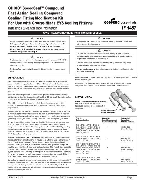
Figure 1 - SpeedSeal Compound Chart<br />
Use chart to determine which size<br />
SpeedSeal cartridge to use for selected<br />
sealing fitting.<br />
CHICO SS2 (2 oz.)<br />
CHICO SS6 (6 oz.)<br />
Fitting Amount of Suggested<br />
Catalog Number SpeedSeal material SpeedSeal<br />
needed (in ounces) Catalog Number<br />
EYS1, EYS16, EYS11, EYS116<br />
EYD1, EYD16, EYD11, EYD116 1 CHICO SS2<br />
EYS2, EYS26, EYS21, EYS216 (2 oz. Cartridge)<br />
EYD2, EYD26, EYD21, EYD216<br />
EYSX11, EYDX11<br />
EYS3, EYS36, EYS31, EYS316<br />
EYD3, EYD36, EYD31, EYD316 2 CHICO SS2<br />
EYSX21, EYDX21 (2 oz. Cartridge)<br />
EYS41, EYS416, EYS4, EYS46<br />
EYD4, EYD46, EYD41, EYD416<br />
EYS51, EYS516, EYS5, EYS56 3 CHICO SS6<br />
EYD5, EYD56, EYD51, EYD516 (6 oz. Cartridge)<br />
EYSX31, EYDX31<br />
EYSX41, EYDX41<br />
EYS61, EYS616, EYS6, EYS66<br />
EYD6, EYD66, EYD61, EYD616 6 CHICO SS6<br />
EYSX51, EYDX51 (6 oz. Cartridge)<br />
<strong>IF</strong> <strong>1457</strong> 03/03 Copyright © 2003, Cooper Industries, Inc. Page 1
Preparing Sealing Fittings<br />
1. Remove the pipe plug(s) from the EYS sealing fitting. See Figure 1.<br />
Figure 1<br />
2. For vertical installations use Chico X fiber to make a dam in the bottom<br />
conduit hub. The dam will prevent the un-gelled SpeedSeal compound from<br />
leaking out of the sealing chamber. No dam is required for horizontal<br />
installations unless it is desired to have compound expand in one direction or<br />
to keep compound out of conduit.<br />
NOTE: SEPARATION OF INDIVIDUAL CONDUCTORS IS NOT<br />
REQUIRED - THE SPEEDSEAL COMPOUND WILL SEPARATE THE<br />
CONDUCTORS AS IT EXPANDS.<br />
3. To properly make dam in conduit hub, use EYS TOOL KIT or hardwood stick,<br />
to force the conductors forward. Do not use metal tools.<br />
4. Pack the fiber into the bottom conduit hub behind the conductors.<br />
5. Push the conductors towards the back of the fitting and pack fiber in bottom<br />
conduit hub in front of conductors. It is not critical that the conductors are<br />
separated because the SpeedSeal compound will expand and fill around the<br />
individual conductors. However, a good dam is required to prevent the fluid<br />
material from leaking out of the sealing chamber.<br />
6. Do not leave any shreds of fiber clinging to the side wall of sealing chamber<br />
or to the conductors. Such shreds when imbedded in the sealing compound<br />
may form leakage channels. The completed dam should be even with the<br />
integral bushing (conduit stop).<br />
7. In vertical installations, if the EYS sealing fitting is the type with two threaded<br />
openings replace the threaded plug in the bottom opening. The sealing<br />
compound will be poured into the top opening. In horizontal installations,<br />
replace the plug in the smaller opening, the sealing compound will be poured<br />
into the larger opening. See Figure 2.<br />
Figure 2<br />
Mixing and Dispensing SpeedSeal Compound<br />
1. READ ALL INSTRUCTIONS PRIOR TO MIXING. SPEEDSEAL<br />
COMPOUND BEGINS TO EXPAND VERY QUICKLY. BE SURE TO<br />
FAMILIARIZE YOURSELF WITH THE INSTRUCTIONS ON THE<br />
FOLLOWING PAGES BEFORE MIXING. THIS WILL ENSURE PROPER<br />
INSTALLATION.<br />
2. Make sure that SpeedSeal material is at a temperature between 50°F (10°C)<br />
and 85° F (29°C).<br />
3. WEAR SAFETY GLASSES AND PROTECTIVE GLOVES.<br />
4. Check the mixing rod to<br />
ensure that it isn't overly SQUEEZE<br />
tight or loose. To do this,<br />
hold the cartridge with<br />
the red end cap facing<br />
up and squeeze the<br />
cartridge in the area<br />
around the plunger. This<br />
will hold plunger in place.<br />
See Figure 3. Turn<br />
counterclockwise slightly<br />
to loosen, then clockwise<br />
to re-tighten snugly.<br />
Figure 3<br />
5. Remove the tape band from the cartridge.<br />
6. Pull the mixing rod up to the top of the<br />
cartridge. See Figure 4.<br />
7. Squeeze the cartridge in the area of the<br />
removed tape band to deform the foil<br />
barrier between the two materials.<br />
See Figure 5.<br />
8. Push the mixing rod all the way in to the bottom of the cartridge (red side).<br />
9. Mix rapidly for 40 to 50 strokes (a stroke is one complete in and out cycle.)<br />
While mixing hold cartridge firmly and turn in a clockwise rotation to make<br />
sure that the plunger is swiping all material in the cartridge. DO NOT MIX<br />
FOR MORE THAN 30 SECONDS. PRESSURE WILL BUILD UP ON THE<br />
INSIDE AFTER 30 SECONDS AS THE MATERIAL STARTS TO EXPAND.<br />
10. At the last stroke, push the mixing<br />
rod all the way in to the bottom (red<br />
side), grasp the cartridge firmly at<br />
the bottom to hold plunger in place<br />
and immediately unscrew the<br />
mixing rod and remove carefully.<br />
See Figure 6.<br />
11. Screw nozzle onto cartridge where<br />
mixing rod was removed. See<br />
Figure 7.<br />
Figure 4<br />
SCREW<br />
NOZZLE INTO<br />
CARTRIDGE<br />
HERE<br />
Figure 7<br />
SQUEEZE<br />
Figure 5<br />
PUSH<br />
DOWN &<br />
UNSCREW<br />
SQUEEZE<br />
PLUNGER TO<br />
KEEP IN PLACE<br />
Figure 6<br />
12. Use the mixing rod to push the plunger. Inject the proper amount of sealing<br />
compound material into the fitting through the EYS threaded opening. See<br />
Table 1 at the beginning of installation instructions for proper amount of<br />
material. Cartridge is marked with incremental 1 ounce segments. See<br />
Figure 8.<br />
Figure 8<br />
<strong>IF</strong> <strong>1457</strong> 03/03 Copyright © 2003, Cooper Industries, Inc. Page 2
13. Replace and tighten the sealing fitting's plug promptly to avoid the<br />
SpeedSeal compound from gelling and fouling the threads. See Figure 9.<br />
Figure 9<br />
14. SpeedSeal material should be used immediately. After one minute dispose<br />
of any unused material.<br />
15. After replacing the plugs attach the red nameplate to the sealing fitting with<br />
the plastic band. Each modification kit is provided with an appropriate<br />
number of nameplates and bands. Position the nameplate for maximum<br />
visibility.<br />
Size<br />
AWG<br />
or KCmII<br />
Table 35.1 The maximum number of conductors that can be sealed in a fitting<br />
The maximum number of #4 type THHN conductors (Column B) permitted<br />
by UL Std. 886 in a 1-1/2” size sealing fitting is 6. The (6) #4 THHN<br />
conductors represents the maximum wire fill of 25% of less for sealing<br />
fittings. Increasing the sealing fitting to a 2” trade size will provide space for<br />
the 40% wire fill, or nine (9) #4 conductors, and comply with UL Std. 886.<br />
The maximum number of wires that can be sealed in a fitting are as follows:<br />
Example of how to use Table 35.1<br />
1/2"<br />
3/4"<br />
1"<br />
1-1/4"<br />
1-1/2"<br />
2"<br />
Seal<br />
Seal<br />
Seal<br />
Seal<br />
Seal<br />
Seal<br />
(Qty/NPT Size) (Qty/NPT Size) (Qty/NPT Size) (Qty/NPT Size) (Qty/NPT Size)<br />
(Qty/NPT Size)<br />
A B A B A B A B A B A B<br />
18 7 11 12 20 20 33 35 58 49 80 80 131<br />
16 6 9 10 16 17 27 30 47 41 64 68 106<br />
14 3 8(13-3/4") 6 15(24/1") 10 24(39/1-1/4") 18 43(69/2") 25 58(94/2") 41 96(154/3")<br />
12 3 6(10-3/4") 5 11(18/1") 8(9/1-1/4" 18(29/1-1/4") 15 32(51/2") 21 43(70/2") 34(35/2-1/2") 71(114/3")<br />
10 1(2-3/4") 4(6-3/4") 4 7(11/1") 7 11(18/1-1/4") 13 20(32/2") 17(18/2") 27(44/2") 29 45(73/3")<br />
8 1 2(3-3/4") 2 4(5/1") 4 6(9/1-1/4") 7 11(16/1-1/2") 9 16(22/2") 16 26(36/2-1/2")<br />
6 1 1 1 2(4/1") 2 4(6/1-1/4") 4(5/1-1/2" 7(11/2") 6 9(15/2") 10(11/2-1/2") 16(26/3")<br />
4 1 1 1 1(2/1") 1 2(4/1-1/4") 3 4(7/2") 5 6(9/2") 8 9(16/3")<br />
3 1 1 1 2(3/1-1/4") 3 3(6/2") 4 5(8/2") 7 8(13/3")<br />
2 1 1 1 1(3/1-1/4") 3 3(5/2") 3(4/2") 4(7/2") 6 7(11/3")<br />
1 1 1 1 1 1 2(3/1-1/2") 3 3(5/2") 4(5/2-1/2") 5(8/3")<br />
1/0 1 1 1 1 2(3/2") 2 2(4/2") 4 4(7/3")<br />
2/0 1 1 1 1(2/1-1/2") 1 2(3/2") 3 3(6/3")<br />
3/0 1 1 1 1 1 1(3/2") 3 3(5/3")<br />
4/0 1 1 1 1 1(2/2") 2 2(4/3")<br />
250 1 1 1 1 1 2(3/2-1/2")<br />
300 1 1 1 1 1 1(3/1-1/2")<br />
350 1 1 1 1 1 1(2/1-1/2")<br />
400 1 1 1 1 1<br />
500 1 1 1 1 1<br />
600 1 1 1<br />
700 1 1 1<br />
750 1 1<br />
800 1 1<br />
900 1 1<br />
1000 1 1<br />
Trade<br />
Size<br />
Conductor<br />
Size Type<br />
Max No.<br />
Permitted for<br />
25% Fill<br />
Max. No. Permitted<br />
for 40% Fill/Trade<br />
Size Sealing Fitting<br />
Needed<br />
1-1/2" #4 THHN (Col.B) 6 (9/2")<br />
In our example, use an EYS6 (for 2” size EYD, EZD, or EZS) sealing fitting.<br />
Col. A = Types RFH-2,<br />
RH, RHH, RHW, THW,<br />
TW, XHHW (AWG 14-6),<br />
FEPB (AWG 6-2).<br />
Col. B - Types FEP,<br />
THHN, THWN, TFN, PF,<br />
PGF, XHHW, (AWG<br />
4-2000 MCM), FEPB<br />
(AWG 14-8).<br />
All statements, technical information and recommendations contained herein are based on information and tests we believe to be reliable. The accuracy<br />
or completeness thereof are not guaranteed. In accordance with Crouse-Hinds "Terms and Conditions of Sale", and since conditions of use are outside<br />
our control, the purchaser should determine the suitability of the product for his intended use and assumes all risk and liability whatsoever in connection<br />
therewith.<br />
Cooper Industries Inc. <strong>IF</strong> <strong>1457</strong><br />
Crouse-Hinds Division <strong>Revision</strong> 1<br />
PO Box 4999, Syracuse, New York 13221 U.S.A. New 03/03<br />
Copyright© 2003, Cooper Industries, Inc.
Le produit SpeedSeal CHICO ®<br />
Produit d'étanchéité à action rapide<br />
Nécessaire de modification des raccords d'étanchéité<br />
Pour utilisation avec les raccords d'étanchéité<br />
EYS de Crouse-Hinds<br />
Instructions d'installation et d'entretienn<br />
CONSERVEZ CES INSTRUCTIONS POUR CONSULTATION FUTURE<br />
PRÉCAUTION<br />
Le produit SpeedSeal de CHICO doit être utilisé seulement avec les raccords<br />
d'étanchéité EYS de Cooper Crouse-Hinds dans les grandeurs commerciales<br />
de ½" à 2". Le composé SpeedSeal convient à la Classe I, division 1 et 2,<br />
groupes C et D, et à la Classe II, division 1 et 2, groupes E, F et G dans les<br />
zones dangereuses seulement, même quand il est utilisé dans un raccord<br />
classé dans le groupe B.<br />
PRÉCAUTION<br />
La température du produit SpeedSeal doit se situer entre 10 °C (50 °F) et 30 °C<br />
(85 °F) avant le mélange. Les raccords d'étanchéité doivent être à une<br />
température supérieure à 4 °C (40 °F). Le produit SpeedSeal gonflera<br />
jusqu'à 4 fois son volume original quand il durcit.<br />
APPLICATION<br />
L'article 501, section 501-5, du National Electrical Code® (NEC) requiert que les<br />
joints d'étanchéité soient installés dans des endroits spécifiques classés Classe I,<br />
divisions 1 et 2. Ceci a pour but de minimiser le passage des gaz et des vapeurs et<br />
d'empêcher le passage de flammes dans les conduits d'une partie à une autre d'une<br />
installation électrique.<br />
Bien que ce ne soit pas requis par le code, il est considéré comme une bonne<br />
pratique de segmenter un long conduit en insérant des joints d'étanchéité à des<br />
distances n'excédant pas 15 à 30 mètres (50 à 100 pieds), selon la dimension du<br />
conduit, pour minimiser les effets d'une « accumulation de pression ».<br />
La section 502-5 du NEC requiert des joints d'étanchéité dans les endroits de<br />
Classe II qui présentent certaines conditions. Les raccords d'étanchéité de Cooper<br />
Crouse-Hinds peuvent être utilisés pour satisfaire ces exigences.<br />
Les joints d'étanchéité des conduits n'ont pas pour but d'empêcher l'écoulement de<br />
liquides, de gaz ou de vapeurs sous un différentiel de pression continu dans tout le<br />
joint. Même à des différences de pression dans le joint équivalentes à quelques<br />
centimètres d'eau, il peut y avoir un lent écoulement de gaz ou de vapeur au travers<br />
le joint et à travers les conducteurs qui passent par le joint.<br />
Les raccords d'étanchéité de Cooper Crouse-Hinds sont enregistrés par<br />
Underwriter's Laboratories, Inc. (UL) pour utilisation dans les endroits dangereux de<br />
Classe I et de Classe II avec le produit d'étanchéité Chico A et la fibre Chico X.<br />
Selon une autre option, les raccords d'étanchéité de type EYS de Cooper Crouse-<br />
Hinds sont également enregistrés UL pour utilisation dans les endroits dangereux de<br />
Classe I, division 1 et 2, groupes C et D, et de Classe II, division 1 et 2, groupes E,<br />
F et G avec le produit d'étanchéité SpeedSeal de Cooper Crouse-Hinds.<br />
Le produit SpeedSeal de Cooper Crouse-Hinds peut être utilisé pour le scellement<br />
d'installations horizontales et verticales. Il peut être utilisé conjointement avec des<br />
raccords d'étanchéité EYS possédant des dimensions commerciales de ½"à 2" dans<br />
les endroits dangereux de Classe I, division 1 et 2, groupes C et D, et de Classe II,<br />
division 1 et 2, groupes E, F et G. Le produit SpeedSeal doit être utilisé avec la fibre<br />
Chico X dans les installations verticales. La fibre Chico X est utilisée pour créer une<br />
barrière pour empêcher le produit SpeedSeal de descendre dans le système de<br />
conduits avant qu'il ne fige.<br />
La barrière n'est pas requise dans les sections horizontales de conduits. Cependant,<br />
si vous voulez empêcher le produit d'étanchéité de gonfler dans les conduits, les<br />
barrières de fibres Chico X devraient être utilisées dans les manchons intégrés des<br />
raccords d'étanchéité.<br />
Le produit SpeedSeal, quand il est correctement mélangé, commence à figer après<br />
environ 4 minutes à 21 °C (70 °F) ou 10 minutes à 4 °C (40 °F) en une masse<br />
dense et solide qui n'est pas affectée par l'eau, n'est pas attaquée par les produits<br />
pétroliers et n'est pas ramollie par la chaleur. Il durcira en moins de 20 minutes et<br />
résistera, avec une grande marge de sécurité, à la pression d'un gaz ou de vapeurs<br />
qui explosent.<br />
PRÉCAUTION<br />
Portez une protection oculaire adéquate et des gants de protection de<br />
plastique quand vous mélangez et injectez le produit SpeedSeal.<br />
<strong>IF</strong> <strong>1457</strong><br />
AVERTISSEMENT<br />
Le contenu générera une pression interne après mélange. Enlevez la tige<br />
d'agitation immédiatement après l'opération de mélange pour empêcher une<br />
accumulation de pression et une éruption soudaine possible du produit qui<br />
pourrait résulter en une blessure corporelle.<br />
Contient de l'isocyanate - peut être un sensibilisateur cutané et respiratoire.<br />
Peut causer une irritation des yeux, de la peau, du nez et de la gorge.<br />
Ne pas inhaler les vapeurs. Utiliser dans un endroit bien aéré. Éviter tout<br />
contact avec les yeux, la peau et les vêtements.<br />
Les conducteurs scellés dans le produit SpeedSeal doivent posséder une isolation<br />
de type thermoplastique ou caoutchouté homologuée.<br />
Les installateurs devraient être formés avant de fabriquer des barrières, des<br />
mélanges ou de mettre le produit en place. Communiquez avec Cooper Crouse-<br />
Hinds pour obtenir un exemplaire de la vidéo d'installation.<br />
INSTALLATION<br />
Figure 1 - Charte du produit SpeedSeal<br />
Utilisez la charte pour déterminer quelle<br />
grosseur de cartouche SpeedSeal vous<br />
devez utiliser pour des raccords<br />
d'étanchéité choisis.<br />
CHICO SS2 (60 ml 2 oz.)<br />
CHICO SS6 (180 ml 6 oz.)<br />
No de catalogue Quantité de produit No de<br />
raccord SpeedSeal requis catalogue du<br />
(en ml et en onces) SpeedSeal<br />
suggéré<br />
EYS1, EYS16, EYS11, EYS116<br />
EYD1, EYD16, EYD11, EYD116 1 CHICO SS2<br />
EYS2, EYS26, EYS21, EYS216 (cartouche de 60 ml<br />
EYD2, EYD26, EYD21, EYD216 ou 2 oz)<br />
EYSX11, EYDX11<br />
EYS3, EYS36, EYS31, EYS316<br />
EYD3, EYD36, EYD31, EYD316 2 CHICO SS2<br />
EYSX21, EYDX21 (cartouche de 60 ml<br />
ou 2 oz)<br />
EYS41, EYS416, EYS4, EYS46<br />
EYD4, EYD46, EYD41, EYD416<br />
EYS51, EYS516, EYS5, EYS56 3 CHICO SS6<br />
EYD5, EYD56, EYD51, EYD516 (cartouche de 180<br />
EYSX31, EYDX31 ml ou 6 oz)<br />
EYSX41, EYDX41<br />
EYS61, EYS616, EYS6, EYS66<br />
EYD6, EYD66, EYD61, EYD616 6 CHICO SS6<br />
EYSX51, EYDX51 (cartouche de 180<br />
ml ou 6 oz)<br />
<strong>IF</strong> <strong>1457</strong> 03/03 © 2003, Cooper Industries, Inc. Page 4
La préparation des raccords d'étanchéité<br />
1. Enlevez le(s) bouchon(s) du raccord d'étanchéité EYS. Voir la figure 1.<br />
Figure 1<br />
2. Pour des installations verticales, utilisez la fibre Chico X pour fabriquer une<br />
barrière dans le bas du raccord de conduit. La barrière empêchera le produit<br />
SpeedSeal non figé de couler à l'extérieur de la chambre du joint. Aucune<br />
barrière n'est requise pour les installations horizontales à moins qu'on ne<br />
veuille avoir un produit gonflé dans une direction ou garder le produit à<br />
l'extérieur du conduit.<br />
NOTE : LA SÉPARATION DES CONDUCTEURS INDIVIDUELS N'EST PAS<br />
REQUISE - LE PRODUIT SPEEDSEAL SÉPARERA LES CONDUCTEURS<br />
QUAND IL GONFLE.<br />
3. Pour construire correctement une barrière dans un raccord de conduit,<br />
utilisez la trousse d'outils EYS ou un bâton de bois dur, pour forcer les<br />
conducteurs vers l'avant. Ne pas utiliser d'outils en métal.<br />
4. Remplissez de fibres la partie inférieure du raccord de tuyau, au-delà des<br />
conducteurs.<br />
5. Poussez les conducteurs vers l'arrière du raccord et remplissez de fibres la<br />
partie inférieure du raccord de tuyau, en avant des conducteurs. Ce n'est<br />
pas critique de séparer les conducteurs parce que le produit SpeedSeal<br />
gonflera et remplira l'espace autour de chaque conducteur. Cependant, une<br />
bonne barrière est requise pour empêcher le matériau fluide de fuir la<br />
chambre du joint.<br />
6. Ne laissez aucune parcelle de fibre coller à la paroi latérale de la chambre<br />
de joint ou aux conducteurs. De telles parcelles intégrées dans le produit<br />
d'étanchéité peuvent former des canaux de fuite. La barrière en entier devrait<br />
être à égalité avec le manchon intégré (bouchon de conduit).<br />
7. Dans les installations verticales, si le raccord d'étanchéité EYS est d'un type<br />
à deux orifices filetés, replacez le bouchon fileté dans l'ouverture du bas. Le<br />
produit d'étanchéité sera introduit par l'ouverture supérieure. Dans les<br />
installations horizontales, replacez le bouchon dans la plus petite ouverture<br />
pour introduire le produit d'étanchéité par l'ouverture la plus grande. Voir la<br />
figure 2.<br />
Figure 2<br />
Mélanger et injecter le produit SpeedSeal<br />
1. LIRE TOUTES LES INSTRUCTIONS AVANT DE MÉLANGER. LE<br />
PRODUIT SPEEDSEAL COMMENCE À GONFLER TRÈS RAPIDEMENT.<br />
ASSUREZ-VOUS DE VOUS FAMILIARISER AVEC LES INSTRUCTIONS<br />
DES PAGES SUIVANTES AVANT DE MÉLANGER. CECI ASSURERA UNE<br />
INSTALLATION CORRECTE.<br />
2. Assurez-vous que le produit SpeedSeal est une température entre 10 °C (50<br />
°F) et 30 °C (85 °F).<br />
3. PORTEZ DES LUNETTES DE SÉCURITÉ ET DES GANTS DE<br />
PROTECTION.<br />
4. Vérifiez la tige de<br />
mélange pour vous<br />
assurer qu'elle n'est ni<br />
trop serrée, ni trop<br />
SERRER<br />
desserrée. Pour faire<br />
cela, tenez la cartouche<br />
avec le bouchon de<br />
l'extrémité rouge vers le<br />
haut et serrez la<br />
cartouche dans la zone<br />
autour du piston. Cela<br />
maintiendra le piston en<br />
place. Voir la figure 3.<br />
Tournez légèrement<br />
dans le sens anti-horaire<br />
pour desserrer, puis<br />
dans le sens horaire<br />
pour resserrer bien en place.<br />
Figure 3<br />
5. Enlevez la bande de ruban de la cartouche.<br />
6. Tirez la tige de mélange vers le haut de<br />
cartouche. Voir la figure 4.<br />
7. Serrez la cartouche dans la zone où la bande<br />
de ruban a été enlevée pour déformer la feuille<br />
de séparation entre les deux matériaux. Voir la<br />
figure 5.<br />
8. Poussez la tige de mélange jusqu'au fond de la cartouche (côté rouge).<br />
9. Mélangez rapidement à l'aide de 40 à 50 coups (un coup est un cycle<br />
complet d'entrée et de sortie). Durant le mélange, tenez la cartouche<br />
fermement et tournez dans le sens horaire pour vous assurer que le piston<br />
agite tout le contenu de la cartouche. NE PAS MÉLANGER PLUS DE 30<br />
SECONDES. LA PRESSION S'ACCUMULERA À l'INTÉRIEUR APRÈS 30<br />
SECONDES QUAND LE MATÉRIEL COMMENCE À GONFLER.<br />
10. Au dernier coup, poussez la tige de<br />
mélange jusqu'au fond (côté<br />
rouge), saisissez la cartouche<br />
fermement par le bas pour tenir le<br />
piston en place, dévissez<br />
immédiatement la tige de mélange<br />
et retirez-la prudemment. Voir la<br />
figure 6.<br />
11. Vissez la buse de coulée sur la<br />
cartouche où la tige de mélange<br />
était fixée. Voir la figure 7.<br />
Figure 4<br />
SERRER<br />
Figure 5<br />
VISSEZ LA BUSE DE<br />
COULÉE DANS LA<br />
CARTOUCHE ICI<br />
Figure 7<br />
POUSSEZ<br />
VERS LE BAS<br />
ET DÉVISSEZ<br />
Figure 6<br />
12. Utilisez la tige de mélange pour pousser le piston. Injectez la quantité<br />
appropriée de produit d'étanchéité dans le raccord par l'orifice fileté EYS.<br />
Voir le tableau 1 au commencement des instructions d'installation pour la<br />
quantité appropriée de matériau. La cartouche est marquée par segment<br />
d'une once (30 ml). Voir la figure 8.<br />
Figure 8<br />
<strong>IF</strong> <strong>1457</strong> 03/03 © 2003, Cooper Industries, Inc. Page 5
13. Replacez et serrez rapidement le bouchon de fixation étanche pour éviter<br />
que le produit SpeedSeal fige et obstrue les filets. Voir la figure 9.<br />
Figure 9<br />
14. Le matériau SpeedSeal devrait être utilisé immédiatement. Après une<br />
minute, jetez tout matériau inutilisé.<br />
15. Après avoir replacé les bouchons, attachez la plaque d'identification rouge<br />
avec la bande de plastique. Chaque nécessaire de modification est fourni<br />
avec un nombre approprié de plaques d'identification et de bandes.<br />
Positionnez la plaque d'identification pour une visibilité maximale.<br />
Grosseur<br />
AWG ou<br />
KCmII<br />
Tableau 35.1 Le nombre maximal de conducteurs qui peuvent être scellés dans un raccord<br />
Le nombre maximal de conducteurs THHN de type 4 (colonne B) permis par<br />
la norme UL 886 dans un raccord d'étanchéité de 1½" est 6. Les<br />
conducteurs THHN de type 4 (6) représentent le remplissage maximal de fils<br />
de 25 % ou moins pour les raccords d'étanchéité. Augmenter le diamètre du<br />
raccord d'étanchéité à 2" fournira de l'espace pour un remplissage de fils de<br />
40 %, ou neuf (9) conducteurs de type 4, et sera conforme à la norme UL<br />
886.<br />
Exemple d'utilisation du tableau 35.1<br />
Grosseur<br />
commerciale<br />
Grosseur du<br />
conducteur Type<br />
No max.<br />
permis<br />
pour un<br />
remplissage<br />
de 25<br />
Bouchon de ½" Bouchon de ¾" Bouchon de 1" Bouchon de 1¼" Bouchon de 1½"<br />
Bouchon de 2"<br />
(Quantite /<br />
(Quantite /<br />
(Quantite /<br />
(Quantite /<br />
(Quantite /<br />
(Quantite /<br />
Grosseur NPT) Grosseur NPT) Grosseur NPT) Grosseur NPT) Grosseur NPT)<br />
Grosseur NPT)<br />
A B A B A B A B A B A B<br />
18 7 11 12 20 20 33 35 58 49 80 80 131<br />
16 6 9 10 16 17 27 30 47 41 64 68 106<br />
14 3 8(13-3/4") 6 15(24/1") 10 24(39/1-1/4") 18 43(69/2") 25 58(94/2") 41 96(154/3")<br />
12 3 6(10-3/4") 5 11(18/1") 8(9/1-1/4" 18(29/1-1/4") 15 32(51/2") 21 43(70/2") 34(35/2-1/2") 71(114/3")<br />
10 1(2-3/4") 4(6-3/4") 4 7(11/1") 7 11(18/1-1/4") 13 20(32/2") 17(18/2") 27(44/2") 29 45(73/3")<br />
8 1 2(3-3/4") 2 4(5/1") 4 6(9/1-1/4") 7 11(16/1-1/2") 9 16(22/2") 16 26(36/2-1/2")<br />
6 1 1 1 2(4/1") 2 4(6/1-1/4") 4(5/1-1/2" 7(11/2") 6 9(15/2") 10(11/2-1/2") 16(26/3")<br />
4 1 1 1 1(2/1") 1 2(4/1-1/4") 3 4(7/2") 5 6(9/2") 8 9(16/3")<br />
3 1 1 1 2(3/1-1/4") 3 3(6/2") 4 5(8/2") 7 8(13/3")<br />
2 1 1 1 1(3/1-1/4") 3 3(5/2") 3(4/2") 4(7/2") 6 7(11/3")<br />
1 1 1 1 1 1 2(3/1-1/2") 3 3(5/2") 4(5/2-1/2") 5(8/3")<br />
1/0 1 1 1 1 2(3/2") 2 2(4/2") 4 4(7/3")<br />
2/0 1 1 1 1(2/1-1/2") 1 2(3/2") 3 3(6/3")<br />
3/0 1 1 1 1 1 1(3/2") 3 3(5/3")<br />
4/0 1 1 1 1 1(2/2") 2 2(4/3")<br />
250 1 1 1 1 1 2(3/2-1/2")<br />
300 1 1 1 1 1 1(3/1-1/2")<br />
350 1 1 1 1 1 1(2/1-1/2")<br />
400 1 1 1 1 1<br />
500 1 1 1 1 1<br />
600 1 1 1<br />
700 1 1 1<br />
750 1 1<br />
800 1 1<br />
900 1 1<br />
1000 1 1<br />
No max. permis<br />
pour un<br />
remplissage de 40%<br />
/ Grosseur com<br />
d'adjustement requis<br />
1-1/2" #4 THHN (Col.B) 6 (9/2")<br />
Dans notre exemple, utilisez un raccord d'étanchéité EYS6 (pour un diam. de 2", EYD, EZD ou EZS).<br />
Les nombres maximaux de fils qui peuvent être scellés dans un raccord sont comme suit :<br />
Col. A =<br />
Types RFH-2,<br />
RH, RHH,<br />
RHW, THW,<br />
TW, XHHW<br />
(AWG 14-6),<br />
FEPB (AWG<br />
6-2).<br />
Col. B -<br />
Types FEP,<br />
THHN,<br />
THWN, TFN,<br />
PF, PGF,<br />
XHHW, (AWG<br />
4-2000<br />
MCM), FEPB<br />
(AWG 14-8).<br />
Tous les énoncés, renseignements techniques et recommandations contenus dans ce document sont basés sur des renseignements et des tests que<br />
nous jugeons dignes de confiance. La précision ou la complétude de ces renseignements ou autres ne sont cependant pas garanties. En accord avec<br />
les conditions de ventes de Crouse-Hinds, et parce que les conditions d'utilisation ne sont pas sous notre contrôle, l'acheteur doit déterminer<br />
l'applicabilité du produit pour son utilisation prévue et assumer tous les risques et responsabilités de quelque nature que ce soit qui s'y rattachent.<br />
Cooper Industries Inc. <strong>IF</strong> <strong>1457</strong><br />
Division Crouse-Hinds Révision 1<br />
B.P. 4999. 13221, Syracuse, New York États-Unis. Nouveau 03/03<br />
© 2003, Cooper Industries, Inc.
Compuesto CHICO ® SpeedSeal<br />
Compuesto Sellante de Acción Rápida<br />
Paquete para Modificar Accesorios para Sello<br />
Para uso con accesorios para sello<br />
EYS de Crouse-Hinds<br />
Información para Instalación y Mantenimiento.<br />
APLICACIÓN<br />
CONSERVE ESTAS INSTRUCCIONES PARA FUTURAS REFERENCIAS<br />
PRECAUCION<br />
El compuesto CHICO SpeedSeal (Sello rápido) esta hecho para utilizarse<br />
únicamente con accesorios para sello del tipo EYS de Cooper Crouse-Hinds<br />
para las medidas comerciales de ½" a 2" (13 mm a 50.8 mm). El compuesto<br />
SpeedSeal (Sello rápido) es adecuado para Areas Peligrosas Clase I,<br />
División 1 y 2, Grupos C & D y Clase II, División 1 y 2, Grupos E, F & G<br />
únicamente, aún cuando se utilice un accesorio clasificado para Grupo B.<br />
PRECAUCION<br />
La temperatura del compuesto SpeedSeal (Sello rápido) debe estar entre 50°F<br />
(10°C) y 85°F (29°C) antes de ser mezclado. Los accesorios para sello deben<br />
estar a una temperatura superior a los 40°F (4°C). El compuesto SpeedSeal<br />
(Sello rápido) se expanderá hasta 4 veces su volumen original cuando ha<br />
curado.<br />
El Código Eléctrico Nacional (NEC por sus siglas en inglés) en el artículo 501,<br />
Sección 501-5, requiere que los sellos sean instalados en lugares específicos en<br />
áreas clasificadas Clase I, División 1 y 2. Esto es para minimizar el paso de gases y<br />
vapores y previene el paso de las flamas a través de una porción de la tubería<br />
conduit a otra de una instalación eléctrica.<br />
Mientras no es un requerimiento del código, es considerada una buena práctica el<br />
seccionar los tramos de tubería conduit que son largos mediante la inserción de<br />
sellos a distancias no mayores de 50 a 100 pies (15 a 30 mts), dependiendo del<br />
tamaño de la tubería conduit, para minimizar los efectos de "presión en cascada".<br />
EL NEC en la Sección 502-5 requiere de sellos en lugares Clase II bajo ciertas<br />
condiciones. Los accesorios para sello Cooper Crouse-hinds pueden ser utilizados<br />
para cumplir estos requerimientos.<br />
Los sellos para tubería conduit no están destinados para prevenir el paso de<br />
líquidos, gases o vapores a una presión diferencial continua a traves del sello. Aún<br />
con diferencias de presión a traves del sello equivalen a unas pocas pulgadas de<br />
agua, esto puede ser un paso lento de gas o vapor a través de un sello y a través<br />
de los conductores pasa a través del sello.<br />
Los accesorios de Cooper Crouse- Hinds están listados por Underwriters<br />
Laboratories, Inc. (UL), para utilizarse en áreas peligrosas Clase I y Clase II con el<br />
compuesto sellador Chico A y la fibra Chico X. Alternativamente, los accesorios<br />
para sello del tipo EYS de Cooper Crouse-Hinds están también listados por UL<br />
para utilizarse en áreas peligrosas Clase I, División 1 y 2, Grupos C & D y Clase II,<br />
División 1 y 2, Grupos E, F & G con el compuesto sellador SpeedSeal de Cooper<br />
Crouse-Hinds.<br />
El compuesto CHICO SpeedSeal (Sello rápido) puede utilizarse para sellar ambas<br />
instalaciones horizontales y verticales. Puede utilizarse con los accesorios para<br />
sello tipo EYS de las medidas ½ " a 2", en áreas peligrosas Clase I, División 1 y 2,<br />
Grupos C y D y Clase II, División 1 y 2, Grupos E, F & G. El compuesto SpeedSeal<br />
(Sello rápido) debe utilizarse con la fibra Chico X en instalaciones verticales. La<br />
fibra Chico X es usada para crear un tapón para prevenir que el material del<br />
SpeedSeal se derrame en la tubería antes de que éste se endurezca. El<br />
taponamiento no se requiere en tramos de tubería verticales.<br />
Sin embargo, si quieres prevenir que el compuesto sellador se exoanda hacia la<br />
tubería, utiliza la fibra Chico X para crear un tapón en el tope integrado que tienen<br />
los accesorios para sello.<br />
El compuesto sellador SpeedSeal, cuando es apropiadamente mezclado, comienza<br />
a solidificar en aproximadamente 4 minutos a 70°F (21°C) o 10 minutos a 40°F<br />
(4°C) y se convierte en una densa, masa sólida a la cual el agua no le afecta, los<br />
productos a base de petróleo no la atacan y no la ablanda el calor. Se endurecerá<br />
en 20 minutos y soportará, con un amplio factor de seguridad, la presión generada<br />
de la explosión de un gas o vapor.<br />
<strong>IF</strong> <strong>1457</strong><br />
PRECAUCION<br />
Utilize la protección apropiada para sus ojos y los guantes de plástico<br />
protectores cuando mezcle e inyecte el compuesto SpeedSeal (Sello rápido)<br />
AVERTISSEMENT<br />
El contenido desarrollará una presión interna después de mezclarse. Retire<br />
la barra mezcladora inmediatamente después de mezclar para prevenir que<br />
la presión aumente y produzca una repentina explosión que podría<br />
lesionarlo.<br />
Contiene isocianato - puede ser sensible a la piel y el olfato. Puede causar<br />
irritación de ojos, piel, nariz y garganta.<br />
No respire los vapores. Utilizese en lugares con una adecuada ventilación.<br />
Evite el contacto con los ojos, piel y ropa.<br />
Los conductores sellados en el compuesto SpeedSeal deben contar con un tipo de<br />
aislamiento termoplástico o neopreno aprobado. Los instaladores deben estar<br />
capacitados antes de hacer el taponeo, mezclado y vaciado del compuesto. Llame a<br />
Cooper Crouse-Hinds para obtener una copia del video de instalación.<br />
INSTALACIÓN<br />
Figura 1 -<br />
Tabla del Compuesto SpeedSeal<br />
Utilice la tabla para determinar el tamaño<br />
de cartucho SpeedSeal a usar para el<br />
accesorio de sellado seleccionado.<br />
CHICO SS2 (60 ml 2 oz.)<br />
CHICO SS6 (180 ml 6 oz.)<br />
Número de Cantidad requerida Número de<br />
Catalogo de material de Catalogo de<br />
SpeedSeal en onzas) SpeedSeal<br />
recomendado<br />
EYS1, EYS16, EYS11, EYS116<br />
EYD1, EYD16, EYD11, EYD116 1 CHICO SS2<br />
EYS2, EYS26, EYS21, EYS216 (Cartucho de 2 oz.<br />
EYD2, EYD26, EYD21, EYD216 56.7 gr)<br />
EYSX11, EYDX11<br />
EYS3, EYS36, EYS31, EYS316<br />
EYD3, EYD36, EYD31, EYD316 2 CHICO SS2<br />
EYSX21, EYDX21 (Cartucho de 2 oz.<br />
56.7 gr)<br />
EYS41, EYS416, EYS4, EYS46<br />
EYD4, EYD46, EYD41, EYD416<br />
EYS51, EYS516, EYS5, EYS56 3 CHICO SS6<br />
EYD5, EYD56, EYD51, EYD516 (Cartucho de 2 oz.<br />
EYSX31, EYDX31 170 gr)<br />
EYSX41, EYDX41<br />
EYS61, EYS616, EYS6, EYS66<br />
EYD6, EYD66, EYD61, EYD616 6 CHICO SS6<br />
EYSX51, EYDX51 (Cartucho de 2 oz.<br />
170 gr)<br />
<strong>IF</strong> <strong>1457</strong> 03/03 © 2003, Cooper Industries, Inc. Page 7
Preparación de los Accesorios para Sello.<br />
1. Retire los tapones para tubería de los accesorios para sello. Vea Figura 1.<br />
Figura 1<br />
2. Para instalaciones verticales utilice la fibra Chico X para elaborar una<br />
barrera en el fondo de la entrada de la tubería conduit. La barrera preveera<br />
que el compuesto SpeedSeal se fuge de la cámara de sellado antes de que<br />
solidifique. Ninguna barrera se requiere para instalaciones horizontales a<br />
menos que se desee tener el compuesto expandido en una dirección o<br />
mantener el compuesto fuera de la tubería.<br />
NOTA: NO SE REQUIERE SEPARAR INDIVIDUALMENTE LOS<br />
CONDUCTORES - EL COMPUESTO SPEEDSEAL SEPARARA LOS<br />
CONDUCTORES CONFORME ÉSTE SE EXPANDA.<br />
3. Para hacer adecuadamente la barrera en el mamelón para entrada de la<br />
tubería conduit, utilice los PAQUETES DE HERRAMIENTA PARA EYS o un<br />
barra de madera dura, para forzar los conductores hacia adentro. No utilice<br />
herramienta metálica.<br />
4. Empaque la fibra hacia el fondo.<br />
5. Jale los conductores hacia atrás del accesorio y atasque la fibra en el fondo<br />
del mamelón de la entrada de tubería conduit al frente de los conductores.<br />
No es crítico que los conductores estén separados debido a que el<br />
compuesto SpeedSeal se expandera y llenará alrededor de cada conductor.<br />
Sin embargo, se requiere de una buena barrera para prevenir que el flujo del<br />
material se fuge de la cámara de sellado.<br />
6. No deje ningún residuo de fibra agarrado a la pared lateral de la cámara de<br />
sellado o a los conductores. Tales residuos cuando quedan embebidos en el<br />
compuesto sellador pueden formar canales de fuga. La barrera terminada<br />
debe estar al ras de la garganta integral de la entrada de la tubería.<br />
7. En instalaciones verticales, sí el accesorio de sello EYS es del tipo con dos<br />
entradas roscadas, coloque el tapón roscado en el fondo de la abertura. El<br />
compuesto sellador se vaciará hacia la parte superior. En instalaciones<br />
horizontales, coloque el tapón en la entrada más pequeña, el compuesto<br />
sellador se vaciará hacia la entrada más grande. Ver figura 2.<br />
Figura 2<br />
Mezclando y Repartiendo el Compuesto SpeedSeal<br />
1. LEA TODAS LAS INSTRUCCIONES ANTES DE MEZCLAR. EL<br />
COMPUESTO SPEEDSEAL EMPIEZA A EXPANDIRSE MUY<br />
RÁPIDAMENTE. ASEGURESE DE FAMILIARIAZARSE CON LAS<br />
INSTRUCCIONES EN LAS SIGUIENTES PÁGINAS ANTES DE MEZCLAR.<br />
ESTO ASEGURARÁ LA CORRECTA INSTALACIÓN.<br />
2. Cerciórese de que el material del SpeedSeal esté a una temperatura entre<br />
50°F (10°C) y 85° F (29°C).<br />
3. UTILICE LENTES DE SEGURIDAD Y GUANTES PROTECTORES.<br />
4. Verifique la barra de<br />
mezclado para asegurar<br />
que ésta no se<br />
encuentre muy apretada Exprimir<br />
o suelta. Para hacer lo<br />
anterior, mantenga el<br />
cartucho con la<br />
terminación roja hacia<br />
arriba y comprima el<br />
cartucho en el área<br />
alrededor del<br />
taponeador. Esto<br />
mantendrá el taponeador<br />
en su lugar. Ver figura 3.<br />
Gire en el sentido<br />
contrario a las<br />
manecillas del reloj para<br />
Figura 3<br />
volver a apretar completamente.<br />
5. Retire la cinta del cartucho.<br />
6. Jale la barra mezcladora hacia arriba a la<br />
parte superior del cartucho. Ver figura 4.<br />
7. Exprima el cartucho en el área de la cinta<br />
retirada para deformar la barrera en forma de<br />
lámina entre los dos materiales. Ver figura 5.<br />
8. Empuje toda la barra mezcladora hacia el fondo del cartucho (lado rojo).<br />
9. Mezcle rápidamente de 40 a 50 agitadas (una agitada es un movimiento<br />
circular completo hacia adentro y hacia afuera .) Mientras esté mezclando<br />
mantenga el cartucho firmemente y gírelo en el sentido contrario a las<br />
manecillas del reloj para asegurar que el taponeador está golpeando todo el<br />
material en el cartucho. NO MEZCLE POR MAS DE 30 SEGUNDOS. LA<br />
PRESION AUMENTARA EN EL INTERIOR DESPUÉS DE 30 SEGUNDOS<br />
TAN PRONTO EL MATERIAL COMIENCE A EXPANDIRSE.<br />
10. En la última agitada, empuje toda<br />
la barra mezcladora en el fondo<br />
(lado rojo), sostenga el cartucho<br />
firmemente en el fondo para<br />
mantener el taponeador en su lugar<br />
e inmediatamente desatornille la<br />
barra mezcladora y retirela<br />
cuidadosamente. Ver Figura 6.<br />
PRESIONE Y<br />
DESATORNILLE<br />
11. 11. Atornille la boquilla en el<br />
cartucho en donde se retiró la barra<br />
mezcladora. Ver Figura 7.<br />
Figura 4<br />
SERRER<br />
Figura 5<br />
ATORNILLE AQUI LA<br />
BOQUILLA EN EL<br />
CARTUCHO<br />
Figura 7<br />
Figura 6<br />
12. Utilice la barra mezcladora para empujar el tapón. Inyecte la cantidad<br />
apropiada de material del compuesto sellador hacia el accesorio a través de<br />
la abertura roscada del EYS. Para la aplicación de la cantidad apropiada del<br />
material del compuesto sellador vea la Tabla 1 al inicio de las instrucciones<br />
de instalación. El cartucho viene marcado con segmentos incrementales de<br />
1 onza (28.3 gr). Ver la Figura 8.<br />
Figura 8<br />
Exprimir<br />
<strong>IF</strong> <strong>1457</strong> 03/03 © 2003, Cooper Industries, Inc. Page 8
13. Coloque y apriete los tapones de los accesorios para sello inmediatamente<br />
para evitar que el compuesto SpeedSeal solidifique y ensucie las roscas. Ver<br />
Figura 9.<br />
Figure 9<br />
14. El material SpeedSeal debe utilizarse inmediatamente. Después de un<br />
minuto deseche todo aquel material que no haya utilizado.<br />
15. Después de colocar los tapones, coloque las placas de datos rojas a los<br />
accesorios para sello con una cinta de plástico. Cada paquete de<br />
modificación es suministrado con el número adecuado de placas de datos y<br />
cintas. Posicione la placa de datos en el lugar más visible que se encuentre.<br />
Calibre<br />
AWG ó<br />
KcmII<br />
Tabla 35.1 El máximo número de conductores que pueden ser sellados en un accesorio<br />
El máximo número de conductores permitidos por la Norma UL 886 en un<br />
accesorio para sello de medida de 1 ½" es 6. Los (6) conductores #4 THHN<br />
representan el espacio máximo de 25% ó menos que pueden ocupar en un<br />
accesorio para sello. Incrementando la medida del accesorio para sello al<br />
tamaño 2", éste suministrará espacio para el 40% de espacio que pueden<br />
ocupar los conductores, o nueve (9) conductores del #4 , y cumplir con los<br />
requerimientos de la norma UL 886.<br />
Ejemplo de cómo utilizar la Tabla 35.1<br />
Medida<br />
Comercial<br />
Calibre del<br />
Conductor Tipo<br />
Max No.<br />
Permitido para<br />
25% espacio<br />
ocupado<br />
½"<br />
¾"<br />
1"<br />
1¼"<br />
1½"<br />
2"<br />
Sello (Cant. / Sello (Cant. / Sello (Cant. / Sello (Cant. /<br />
Sello (Cant. /<br />
Sello (Cant. /<br />
Medida NPT ) Medida NPT ) Medida NPT ) Medida NPT ) Medida NPT )<br />
Medida NPT )<br />
A B A B A B A B A B A B<br />
18 7 11 12 20 20 33 35 58 49 80 80 131<br />
16 6 9 10 16 17 27 30 47 41 64 68 106<br />
14 3 8(13-3/4") 6 15(24/1") 10 24(39/1-1/4") 18 43(69/2") 25 58(94/2") 41 96(154/3")<br />
12 3 6(10-3/4") 5 11(18/1") 8(9/1-1/4" 18(29/1-1/4") 15 32(51/2") 21 43(70/2") 34(35/2-1/2") 71(114/3")<br />
10 1(2-3/4") 4(6-3/4") 4 7(11/1") 7 11(18/1-1/4") 13 20(32/2") 17(18/2") 27(44/2") 29 45(73/3")<br />
8 1 2(3-3/4") 2 4(5/1") 4 6(9/1-1/4") 7 11(16/1-1/2") 9 16(22/2") 16 26(36/2-1/2")<br />
6 1 1 1 2(4/1") 2 4(6/1-1/4") 4(5/1-1/2" 7(11/2") 6 9(15/2") 10(11/2-1/2") 16(26/3")<br />
4 1 1 1 1(2/1") 1 2(4/1-1/4") 3 4(7/2") 5 6(9/2") 8 9(16/3")<br />
3 1 1 1 2(3/1-1/4") 3 3(6/2") 4 5(8/2") 7 8(13/3")<br />
2 1 1 1 1(3/1-1/4") 3 3(5/2") 3(4/2") 4(7/2") 6 7(11/3")<br />
1 1 1 1 1 1 2(3/1-1/2") 3 3(5/2") 4(5/2-1/2") 5(8/3")<br />
1/0 1 1 1 1 2(3/2") 2 2(4/2") 4 4(7/3")<br />
2/0 1 1 1 1(2/1-1/2") 1 2(3/2") 3 3(6/3")<br />
3/0 1 1 1 1 1 1(3/2") 3 3(5/3")<br />
4/0 1 1 1 1 1(2/2") 2 2(4/3")<br />
250 1 1 1 1 1 2(3/2-1/2")<br />
300 1 1 1 1 1 1(3/1-1/2")<br />
350 1 1 1 1 1 1(2/1-1/2")<br />
400 1 1 1 1 1<br />
500 1 1 1 1 1<br />
600 1 1 1<br />
700 1 1 1<br />
750 1 1<br />
800 1 1<br />
900 1 1<br />
1000 1 1<br />
Max. No. Permitido para 40%<br />
espacio ocupado / Medida Comercial<br />
del Accesorio para Sello Requerido<br />
1-1/2" #4 THHN (Col.B) 6 (9/2")<br />
En nuestro ejemplo, utilizar un accesorio para sello EYS6 (EYD, EZD O EZS para medida de 2").<br />
El máximo número de cables que pueden ser sellados en un accesorio es de la manera siguiente:<br />
Col. A =<br />
Tipos RFH-2,<br />
RH, RHH,<br />
RHW, THW,<br />
TW, XHHW<br />
(AWG 14-6),<br />
FEPB (AWG<br />
6-2).<br />
Col. B -<br />
Tipos FEP,<br />
THHN,<br />
THWN, TFN,<br />
PF, PGF,<br />
XHHW, (AWG<br />
4-2000<br />
MCM), FEPB<br />
(AWG 14-8).<br />
Todas las indicaciones, información técnica y recomendaciones contenidas en este documento están basadas en infomación y pruebas que<br />
consideramos son confiables. La precisión ó totalidad de la información no está garantizada. De acuerdo con los términos de venta de Crouse-Hinds,<br />
y debido a que las condiciones de uso están fuera de nuestro control, el comprador debe determinar la aplicabilidad del producto para el uso que<br />
pretenda y asume todos los riesgos y responsabilidades de cualquier cosa que además tenga conexión con este<br />
Cooper Industries Inc. <strong>IF</strong> <strong>1457</strong><br />
Crouse-Hinds Division <strong>Revision</strong> 1<br />
P.O. Box 4999, Syracuse, New York 13221 USA New 03/03<br />
© 2003, Cooper Industries, Inc.