SunSmartTM Digital Timer - Jasco Products
SunSmartTM Digital Timer - Jasco Products
SunSmartTM Digital Timer - Jasco Products

You also want an ePaper? Increase the reach of your titles
YUMPU automatically turns print PDFs into web optimized ePapers that Google loves.
SunSmart TM <strong>Digital</strong> <strong>Timer</strong><br />
Installation<br />
Instructions<br />
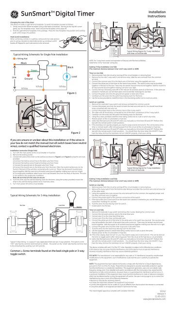
Changing the color of the timer<br />
This device includes a Light Almond Faceplate. To switch faceplates proceed as follows:<br />
1. Gently remove the White Faceplate using a flat head screwdriver. Starting at the top left corner<br />
gently pry the faceplate loose. Work around the faceplate until it pops off.<br />
2. Find the Light Almond Faceplate in the package. Place the new faceplate into position and carefully<br />
push until it snaps into position.<br />
Multi-Switch Installations<br />
When combining controls in a wall box, remove all inner side sections<br />
prior to wiring. Use pliers to bend side section up and down until it<br />
breaks off. Repeat for each side section to be removed.<br />
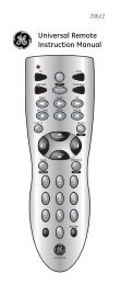
Typical Wiring Schematic for Single Pole Installation<br />
= Wiring Nut<br />
Black<br />
Blue<br />
Black<br />
Green <strong>Timer</strong><br />
Line<br />
Ground<br />
White<br />
White<br />
BLACK<br />
WHITE<br />
BLUE<br />
GREEN<br />
RED<br />
White<br />
Load<br />
Figure 1<br />
Figure 2<br />
GROUND<br />
3<br />
C<br />
JUMPER<br />
5<br />
Load<br />
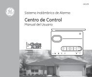
NOTE: For 3-way timer control and operation of fixtures with Mechanical Ballast,<br />
install timer in the “load side” wiring box.<br />
Existing 3-Way Installation Line Side<br />
(The maximum distance between timer and 3-way switch is 100ft)<br />
2<br />
4<br />
1 = Line<br />
2 = Neutral<br />
3 = Ground<br />
4 = Load<br />
5 = Traveler<br />
C = Common<br />
<strong>Timer</strong> on Line Side<br />
1. Remove power from the circuit by turning off the circuit breaker or removing fuse.<br />
2. Remove the line side 3-way switch and remove wires, label the wire removed from the common<br />
terminal.<br />
3. Connect the common wire (1) to the black wire of the timer using the supplied wire nuts<br />
4. Connect the white wire of the timer to the neutral wire (white). The neutral wires may be bundled<br />
together in the back of the box. There may be several neutral wires bound together. Add the neutral to<br />
all neutral wires bound together making sure wire nut is tight.<br />
5. Connect the two remaining wires left to the red wire (5) and blue wires (4) of the timer. If the wires are<br />
colored or marked you can tell them apart and record their markings for use later.<br />
6. Connect the green wire (3) to the ground wire (green or bare wire in box).<br />
7. Carefully tuck the wires into the switch box leaving room for the timer.<br />
8. Use the screws provided to install the timer in the box being careful not to crush any wires.<br />
Switch on Load Side<br />
1. Remove the Load side 3-way switch and remove and label the common wire (4).<br />
2. Connect the jumper wire from the switch to both the load wire and wire (4). You should have three<br />
wires connected with one wire nut.<br />
3. Connect the jumper back to the common input of the 3-way switch.<br />
4. The other wire (5) should stay connected to one of the other connections of the 3-way switch.<br />
5. Carefully tuck the wires into the switch box leaving room for the timer.<br />
6. Using the screws provided install the timer being careful not to crush or pinch any wires.<br />
7. Restore power at the circuit breaker or fuse box.<br />
8. Verify that the load turns ON and OFF when you manually turn the timer ON and OFF. Perform this<br />
test with the remote switch in both positions.<br />
9. If the load does not operate properly you need to swap wire (4) and wire (5). This can be done at the<br />
timer or remote switch, after removing power from the circuit at the circuit breaker or fuse box.<br />
10. Verify that the load turns ON and OFF when you manually turn the timer ON and OFF. Perform this<br />
test with the remote switch in both positions. You should hear the timer relay click ON/OFF. If you<br />
hear the relay click but the load does not turn ON/OFF properly, check your wiring.<br />
BLACK<br />
WHITE<br />
RED<br />
BLUE<br />
GREEN<br />
1<br />
2<br />
5<br />
4<br />
3<br />
Line<br />
Typical Wiring Digram for 3-way installation<br />
with timer on hot/line side<br />
H<br />
If you are unsure or unclear about this installation or if the wires in<br />
your box do not match the manual (not all switch boxes have neutral<br />
wires), contact a qualified licensed electrician.<br />
Installation Instruction (Single Pole)<br />
1. Turn OFF the main power at the circuit breaker or fuse box.<br />
2. Remove the existing switch.<br />
3. Connect the wires of the timer to the wall box as shown in Figure 1 and Figure 2 using the wire nuts<br />
provided.<br />
a) Connect the hot/live wire of line to the black wire from <strong>Timer</strong>.<br />
b) Connect the hot/live wire of load to the blue wire from <strong>Timer</strong>.<br />
c) Connect the ground wire to the green wire from <strong>Timer</strong>.<br />
d) Connect the neutral wire to the white wire from the timer. Often the neutral (white) wire can be<br />
found in the back of the wire box connected with a wire nut. There may be several neutral wires<br />
bound together. Add the neutral to all neutral wires bound together making sure wire nut is tight.<br />
e) For single pole installation attach wire nut to red (traveler) wire from the back of the timer. This wire<br />
is not needed in the single pole installation.<br />
Note: Be sure that all wire nuts are secure.<br />
4. Tuck the wires into the wall box leaving room for the timer. Using the screws provided, mount the<br />
timer to the wall box being careful not to crush any wires.<br />
5. Turn main power ON at the circuit breaker.<br />
Typical Wiring Schematic for 3-Way Installation<br />
H<br />
C<br />
Hot Side<br />
Line<br />
Load Side<br />
Neutral<br />
Typical 3-Way Wiring: In a typical 3-way application there are two 3-way switches. The switch on the<br />
“HOT” side has the common terminal tied to 120VAC. The switch on the “LOAD” side has the common tied<br />
to the lamp/load the switches turn OFF and ON.<br />
Common = Screw terminals found on the back single pole or 3-way<br />
toggle switch.<br />
H<br />
H<br />
C<br />
GROUND<br />
3<br />
C<br />
5<br />
Line<br />
Existing 3-Way Installation Load Side<br />
(The maximum distance between timer and 3-way switch is 100ft)<br />
2<br />
1<br />
1 = Line<br />
2 = Neutral<br />
3 = Ground<br />
4 = Load<br />
5 = Traveler<br />
C = Common<br />
Switch on Line Side<br />
1. Remove power from the circuit by turning off the circuit breaker or removing fuse.<br />
2. Remove the 3way switch from the hot/line side. Remove and label the common wire and remove one<br />
of the other wires.<br />
3. Using the supplied wire nuts connect the wire removed from the common, the supplied jumper, and<br />
the other removed wire (1) together.<br />
4. Connect the jumper back to the common connection of the switch.<br />
5. If the two wires wire (1) and wire (5) on the switch are colored or marked so you can tell them apart<br />
record their markings for use later.<br />
6. Tuck the wires into box leaving room for switch.<br />
7. Install switch into the box.<br />
<strong>Timer</strong> on Load Side<br />
1. Remove the load side 3-way switch and remove the 3 wires, labeling the common wire.<br />
2. Connect the removed common wire to the timer blue wire.<br />
3. Connect wire (1) to the timer black (line) wire.<br />
4. Connect wire (5) to the timer red (traveler) wire.<br />
5. Connect the white wire (1) of the timer to the white wire in the switch box (neutral). The neutral wires<br />
may be bundled in the back of the switch box with a wire nut. There may be several neutral wires<br />
bound together. Add the neutral to all neutral wires bound together making sure the wire nut is tight.<br />
6. Connect the green wire (3) of the timer to ground in the switch box.<br />
7. Tuck the wires into the switch box leaving room for the timer.<br />
8. Use the supplied screws to install timer being careful not to crush or pinch the wires.<br />
9. Restore power at the circuit breaker or fuse box.<br />
10. If the timer display does not turn on, you may need to swap wire (1) and wire (5). This can be done at<br />
the timer or toggle switch, after removing power from the circuit at the fuse box or circuit breaker.<br />
11. Verify that the load turns ON and OFF when you manually turn the timer ON and OFF. Perform this<br />
test with the remote switch in both positions. You should hear the timer relay click ON/OFF. If you<br />
hear the relay click but the load does not turn ON/OFF properly, check your wiring<br />
This device complies with part 15 of the FCC rules. Operation is subject to the following two conditions:<br />
(1) this device may not cause harmful interference, and (2) this device must accept any interference<br />
received, including interference that may cause undesired operation.<br />
FCC NOTE: The manufacturer is not responsible for any radio or TV interference caused by unauthorized<br />
modifications to this equipment. Such modifications could void the user’s authority to operate the<br />
equipment.<br />
BLACK<br />
WHITE<br />
RED<br />
BLUE<br />
GREEN<br />
Typical Wiring Digram for 3-way installation<br />
with timer on load side<br />
1<br />
2<br />
5<br />
4<br />
3<br />
Load<br />
NOTE: This equipment has been tested and found to comply with the limits for a Class B digital device,<br />
pursuant to Part 15 of the FCC Rules. These limits are designed to provide reasonable protection against<br />
harmful interference in a residential installation. This equipment generates, uses and can radiate radio<br />
frequency energy and, if not installed and used in accordance with the instructions may cause harmful<br />
interference to radio communications. However, there is no guarantee that interference will not occur in<br />
a particular installation. If this equipment does cause harmful interference to radio or television reception,<br />
which can be determined by turning the equipment off and on, the user is encourage to try to correct the<br />
interference by one or more of the following measures:<br />
• Reorient or relocate the receiving antenna.<br />
• Increase the separation between the equipment and receiver.<br />
• Connect the equipment into an outlet on a circuit different from that to which the receiver is connected.<br />
• Consult the dealer or an experienced radio/TV technician for help.<br />
This Class B digital apparatus complies with Canadian ICES-003. 15312<br />
Version 3<br />
11-03-2011<br />
www.jascoproducts.com
Temporizador <strong>Digital</strong> SunSmart TM<br />
Instrucciones<br />
de instalación<br />
Cambiar el color del temporizador<br />
Este dispositivo incluye una placa frontal color almendra claro. Para cambiar las placas frontales siga los<br />
siguientes pasos:<br />
1. 1. Retire cuidadosamente la placa frontal blanca con un destornillador de cabeza plana. Comenzando<br />
desde la esquina superior izquierda, afloje ligeramente la placa frontal haciendo palanca hasta retirarla.<br />
2. 2. Busque la placa frontal color almendra claro dentro del paquete. Coloque la nueva placa frontal y<br />
presione cuidadosamente hasta que encaje en su lugar.<br />
Instalación de múltiples interruptores<br />
Cuando combine controles en una caja de embutir, retire todas las<br />
secciones laterales internas antes de realizar la conexión. Utilice<br />
pinzas para mover la sección lateral de arriba hacia abajo hasta<br />
quebrarla. Repita el procedimiento con cada sección lateral que<br />
retire.<br />
Esquema de cableado típico para la instalación de un solo polo<br />
Cable<br />
Negro<br />
Blanco<br />
Verde<br />
Conexión<br />
a tierra<br />
Blanco<br />
NEGRO<br />
Temporizador<br />
Azul<br />
= Empalme<br />
de cable<br />
Blanco<br />
Negro<br />
Carga<br />
Figura 1<br />
Lado de cable de instalación de 3 vías existente<br />
(la distancia máxima entre el temporizador y el interruptor de 3 vías es de 100 pies)<br />
Temporizador en el lado del cable<br />
1. Desconecte el circuito desactivando el disyuntor o retirando el fusible.<br />
2. Retire el interruptor de 3 vías del lado del cable y los cables, y marque el cable que retiró del terminal<br />
común.<br />
3. Conecte el cable común (1) al cable negro del temporizador usando los empalmes de cable<br />
suministrados.<br />
4. Conecte el cable blanco del temporizador al cable neutro (blanco). Los cables neutros pueden estar<br />
amarrados en la parte trasera de la caja. Puede haber varios cables neutros amarrados. Incluya el<br />
neutro a todos los cables neutros amarrados asegurándose de que el empalme de cable esté ajustado.<br />
5. Conecte los dos cables restantes al cable rojo (5) y a los cables azules (4) del temporizador. Si los cables<br />
están coloreados o marcados, puede identificarlos y registrar las marcas para usarlos más adelante.<br />
6. Conecte el cable verde (3) al cable de conexión a tierra (cable verde o cable sin revestir de la caja).<br />
7. Introduzca cuidadosamente los cables en la caja del interruptor dejando espacio para el temporizador.<br />
8. Utilice los tornillos provistos para instalar el temporizador en la caja teniendo cuidado de no apretar los<br />
cables.<br />
Interruptor en el lado de carga<br />
1. Retire el interruptor de 3 vías del lado de carga y marque el cable común (4).<br />
2. Conecte el cable de puente del interruptor al cable de carga y al cable (4). Debe tener tres cables<br />
conectados con un empalme de cable.<br />
3. Conecte nuevamente el puente a la entrada del terminal común del interruptor de 3 vías.<br />
4. El otro cable (5) debe permanecer conectado a una de las otras conexiones del interruptor de 3 vías.<br />
5. Introduzca cuidadosamente los cables en la caja del interruptor dejando espacio para el temporizador.<br />
6. Usando los tornillos provistos, instale el temporizador, teniendo cuidado de no apretar o pellizcar los<br />
cables.<br />
7. Restablezca la electricidad desde el disyuntor o caja de fusibles.<br />
8. Verifique que la carga se conecte y desconecte cuando enciende y apaga manualmente el<br />
temporizador. Realice esta prueba con el interruptor remoto en ambas posiciones.<br />
9. Si la carga no funciona adecuadamente debe intercambiar el cable (4) y el cable (5). Esto puede<br />
realizarse en el temporizador o interruptor remoto, después de desconectar la electricidad del circuito<br />
desde el disyuntor o caja de fusibles.<br />
10. Verifique que la carga se conecte y desconecte cuando enciende y apaga manualmente el<br />
temporizador. Realice esta prueba con el interruptor remoto en ambas posiciones. Debe escuchar un<br />
“clic” cuando el relé del temporizador se enciende y apaga. Si escucha el “clic” del relé pero la carga no<br />
se enciende ni apaga correctamente, revise el cableado.<br />
BLANCO<br />
Cable<br />
Carga<br />
CONEXIÓN A TIERRA<br />
3<br />
NEGRO<br />
AZUL<br />
BLANCO<br />
1<br />
H<br />
Si no está seguro o tiene dudas sobre esta instalación, o si los<br />
cables de su caja no coinciden con los que se indican en el manual<br />
(no todas las cajas de interruptores tienen conductores neutros),<br />
contacte a un electricista profesional capacitado.<br />
Instrucciones de instalación (un solo polo)<br />
1. Desconecte la electricidad principal del disyuntor o caja de fusibles.<br />
2. Retire el interruptor existente.<br />
3. Conecte los cables del temporizador a la caja de embutir como se muestra en las Figuras 1 y 2, utilice<br />
los empalmes de cable provistos.<br />
a) Conecte el cable electrizado/con corriente de la línea al cable negro del temporizador.<br />
b) Conecte el cable electrizado/con corriente de carga al cable azul del temporizador.<br />
c) Conecte el cable de conexión a tierra al cable verde del temporizador.<br />
d) Conecte el cable neutro al cable blanco del temporizador. Muchas veces, el cable neutro (blanco)<br />
se puede encontrar en la parte trasera de la caja de embutir conectado con un empalme de cable.<br />
Puede haber varios cables neutros amarrados. Incluya el neutro a todos los cables neutros amarrados<br />
asegurándose de que el empalme de cable esté ajustado.<br />
e) Para la instalación de un solo polo, fije un empalme de cable al cable rojo (conmutador) de la parte<br />
trasera del temporizador. Este cable no es necesario para la instalación de un solo polo.<br />
Nota: Asegúrese de que todos los empalmes de cable estén ajustados.<br />
4. Introduzca el cable en la caja de embutir, dejando espacio para el temporizador. Use los tornillos<br />
provistos para instalar el temporizador en la caja de embutir, teniendo cuidado de no apretar los cables.<br />
5. Conecte la corriente principal del disyuntor.<br />
Esquema de cableado típico para la instalación de 3 vías<br />
H<br />
Lado con corriente<br />
Cable<br />
VERDE<br />
ROJO<br />
Lado de carga<br />
Figura 2<br />
H<br />
Neutro<br />
H<br />
C<br />
5<br />
2<br />
1<br />
1 = Cable<br />
2 = Neutro<br />
3 = Conexión<br />
a tierra<br />
4 = Carga<br />
5 = Conmutador<br />
C = Común<br />
Lado de carga de instalación de 3 vías existente<br />
(la distancia máxima entre el temporizador y el interruptor de 3 vías es de 100 pies)<br />
Interruptor en el lado de cable<br />
1. Desconecte el circuito desactivando el disyuntor o retirando el fusible.<br />
2. Retire el interruptor de 3 vías del lado de cable con corriente. Retire y marque el cable común y quite<br />
uno de los otros cables.<br />
3. Con los empalmes de cable suministrados conecte el cable que retiró del cable común, el puente<br />
suministrado y el otro cable que haya retirado (1).<br />
4. Conecte nuevamente el puente a la conexión común del interruptor.<br />
5. Si los dos cables (1) y (5) en el interruptor están coloreados o marcados para que pueda distinguirlos,<br />
registre las marcas para usarlos más adelante.<br />
6. Introduzca los cables en la caja dejando espacio para el interruptor.<br />
7. Instale el interruptor en la caja.<br />
Temporizador en el lado de carga<br />
1. Retire el interruptor de 3 vías del lado de carga y los 3 cables y marque el cable común.<br />
2. Conecte el cable común que retiró al cable azul del temporizador.<br />
3. Conecte el cable (1) al cable (línea) negro del temporizador.<br />
4. Conecte el cable (5) al cable (conmutador) rojo del temporizador.<br />
5. Conecte el cable blanco (1) del temporizador al cable blanco en la caja de interruptores (neutro). Los<br />
cables neutros Pueden estar amarrados en la parte trasera de la caja de interruptores con un empalme<br />
de cable. Puede haber varios cables neutros amarrados. Incluya el neutro a todos los cables neutros<br />
amarrados asegurándose de que el empalme del cable esté ajustado.<br />
6. Conecte el cable verde (3) del temporizador a la conexión a tierra en la caja de interruptores.<br />
7. Introduzca los cables en la caja de interruptores dejando espacio para el temporizador.<br />
8. Utilice los tornillos provistos para instalar el temporizador teniendo cuidado de no apretar o pellizcar<br />
los cables.<br />
9. Restablezca la electricidad desde el disyuntor o caja de fusibles.<br />
10. Si la pantalla del temporizador no se enciende, es posible que deba intercambiar el cable (1) y (5). Esto<br />
puede realizarse en el temporizador o interruptor de palanca, después de desconectar la electricidad<br />
del circuito desde el disyuntor o caja de fusibles.<br />
11. Verifique que la carga se conecte y desconecte cuando enciende y apaga manualmente el<br />
temporizador. Realice esta prueba con el interruptor remoto en ambas posiciones. Debe escuchar un<br />
“clic” cuando el relé del temporizador se enciende y apaga. Si escucha el “clic” del relé pero la carga no<br />
se enciende ni apaga correctamente, revise el cableado.<br />
ROJO<br />
AZUL<br />
VERDE<br />
Diagrama de cableado típico para la instalación de<br />
3 vías con temporizador en la línea del lado de carga<br />
2<br />
5<br />
4<br />
3<br />
C<br />
C<br />
Este dispositivo cumple con la Parte 15 de las Normas de la FCC. La operación está sujeta a las siguientes<br />
dos condiciones: (1) este dispositivo no puede causar interferencias perjudiciales y (2) este dispositivo debe<br />
aceptar cualquier interferencia recibida, incluidas las interferencias que puedan provocar una operación<br />
indeseable.<br />
Cableado típico de 3 vías: En una aplicación típica de 3 vías hay dos interruptores de 3 vías. El interruptor<br />
del lado con “CORRIENTE” tiene el terminal común conectado a 120 VCA. El interruptor del lado de “CARGA”<br />
tiene el terminal común fijado a la lámpara/carga que los interruptores conectan o desconectan.<br />
Común = Terminales con tornillos ubicados en el interruptor de<br />
palanca de 3 vías o unipolar trasero.<br />
CONEXIÓN A TIERRA<br />
C<br />
3<br />
PUENTE<br />
Carga<br />
2<br />
4<br />
NEGRO<br />
BLANCO<br />
ROJO<br />
AZUL<br />
1<br />
2<br />
5<br />
4<br />
Cable<br />
Advertencia: Los cambios o modificaciones a esta unidad que no hayan sido expresamente aprobados<br />
por la parte responsable del cumplimiento de las reglas, pueden anular la autoridad del usuario para poder<br />
operar el equipo.<br />
NOTA: Este equipo ha sido probado y cumple con los límites para un dispositivo digital de Clase B, de<br />
conformidad con la Parte 15 de las Normas de la FCC. Estos límites están diseñados para proporcionar<br />
una protección razonable contra interferencias en una instalación residencial. Este equipo genera, utiliza y<br />
puede irradiar energía de radiofrecuencia y, si no se instala y utiliza de acuerdo con las instrucciones, puede<br />
causar interferencia dañina a la comunicación por radio.<br />
Sin embargo, no hay ninguna garantía que no ocurra interferencia en una instalación en particular. Si este<br />
equipo causa interferencias perjudiciales a la recepción de radio o televisión, esto se puede comprobar<br />
apagando y encendiendo el equipo repetidamente, se le sugiere al usuario tratar de remediar la<br />
interferencia tomando una o más de las siguientes medidas.<br />
• Reorientar o reubicar la antena de recepción<br />
• Aumentar la separación entre el equipo y el receptor<br />
• Conectar el equipo a un tomacorriente en un circuito distinto de aquel al que está conectado el receptor<br />
• Consultar al distribuidor o a un técnico de radio / TV para obtener ayuda.<br />
5<br />
1 = Cable<br />
2 = Neutro<br />
3 = Conexión<br />
a tierra<br />
4 = Carga<br />
5 = Conmutador<br />
C = Común<br />
VERDE<br />
Diagrama de cableado típico para la instalación de<br />
3 vías con temporizador en el lado del cable con corriente<br />
3<br />
NOTA: Para el control del temporizador de 3 vías y el funcionamiento de los aparatos con balasto mecánico,<br />
instalar el temporizador en la caja de “carga lateral” de cableado.<br />
15312<br />
Version 3<br />
11-03-2011<br />
www.jascoproducts.com