GM-X544 - Service.pioneer-eur.com - Pioneer
GM-X544 - Service.pioneer-eur.com - Pioneer
GM-X544 - Service.pioneer-eur.com - Pioneer

You also want an ePaper? Increase the reach of your titles
YUMPU automatically turns print PDFs into web optimized ePapers that Google loves.
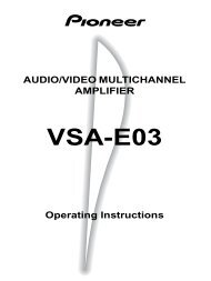
BRIDGEABLE FOUR-CHANNEL<br />
POWER AMPLIFIER<br />
Before Using This Product<br />
Setting the Unit<br />
AMPLIFICADOR DE POTENCIA DE<br />
CUATRO CANALES EN PUENTE<br />
Thank you for purchasing this PIONEER<br />
product. Before attempting operation, be<br />
sure to read this manual.<br />
Gain Control<br />
Power Indicator<br />
Owner’s Manual<br />
PIONEER CORPORATION<br />
4-1, MEGURO 1-CHOME, MEGURO-KU, TOKYO 153-8654, JAPAN<br />
PIONEER ELECTRONICS (USA) INC.<br />
P.O. Box 1760, Long Beach, California 90801, U.S.A.<br />
TEL: (800) 421-1404<br />
PIONEER ELECTRONIC (EUROPE) N.V.<br />
Haven 1087 Keetberglaan 1, 9120 Melsele, Belgium<br />
TEL: (0) 3/570.05.11<br />
PIONEER ELECTRONICS AUSTRALIA PTY. LTD.<br />
178-184 Boundary Road, Braeside, Victoria 3195, Australia<br />
TEL: (03) 9586-6300<br />
PIONEER ELECTRONICS OF CANADA, INC.<br />
300 Allstate Parkway, Markham, Ontario L3R 0P2, Canada<br />
TEL: (905) 479-4411<br />
PIONEER ELECTRONICS DE MEXICO, S.A. de C.V.<br />
San Lorenzo Num 1009 3er piso Desp. 302<br />
Col. Del Valle, Mexico D.F. C.P. 03100<br />
TEL: 5-688-52-90<br />
<br />
<strong>GM</strong>-<strong>X544</strong><br />
Manual del Propietario<br />
Published by <strong>Pioneer</strong> Corporation.<br />
Copyright © 2000 by <strong>Pioneer</strong> Corporation.<br />
All rights reserved.<br />
Publicado por <strong>Pioneer</strong> Corporation.<br />
Copyright © 2000 <strong>Pioneer</strong> Corporation.<br />
Todos los derechos reservados.<br />
Printed in U.S.A.<br />
Impreso en los EE.UU.<br />
ES<br />
In case of trouble<br />
When the unit does not operate properly,<br />
contact your dealer or the nearest authorized<br />
PIONEER <strong>Service</strong> Station.<br />
WARNING<br />
• Always use the special red battery and ground<br />
wire [RD-223], which is sold separately. Connect<br />
the battery wire directly to the car battery positive<br />
terminal (+) and the ground wire to the car body.<br />
• Do not touch the amplifier with wet hands.<br />
Otherwise you may get an electric shock. Also, do<br />
not touch the amplifier when it is wet.<br />
• For traffic safety and to maintain safe driving<br />
conditions, keep the volume low enough so that<br />
you can still hear normal traffic sound.<br />
• Check the connections of the power supply and<br />
speakers if the fuse of the separately sold battery<br />
wire or the amplifier fuse blows. Detect the cause<br />
and solve the problem, then replace the fuse with<br />
another one of the same size and rating.<br />
• To prevent malfunction of the amplifier and<br />
speakers, the protective circuit will cut the power<br />
supply to the amplifier (sound will stop) when an<br />
abnormal condition occurs. In such a case, switch<br />
the power to the system OFF and check the<br />
connection of the power supply and speakers.<br />
Detect the cause and solve the problem.<br />
• Contact the dealer if you cannot detect the cause.<br />
• To prevent an electric shock or short-circuit<br />
during connection and installation, be sure to<br />
disconnect the negative (–) terminal of the battery<br />
beforehand.<br />
• Confirm that no parts are behind the panel when<br />
drilling a hole for installation of the amplifier. Be<br />
sure to protect all cables and important equipment<br />
such as fuel lines, brake lines and the electrical<br />
wiring from damage.<br />
Adjusting the gain controls A and B will<br />
help match the output of the car stereo to<br />
the <strong>Pioneer</strong> amplifier. Normally, set the<br />
gain controls to the “NORMAL” position.<br />
If the output is low, even when the<br />
volume of the car stereo is turned up,<br />
turn these controls clockwise. If there is<br />
distortion when the volume of the car<br />
stereo is turned up, turn these controls<br />
counter-clockwise.<br />
• If you only use one input plug, set the gain<br />
controls for speaker outputs A and B to the<br />
same position.<br />
• When using with an RCA equipped car<br />
stereo (standard output of 500 mV), set to<br />
the NORMAL position. When using with<br />
an RCA equipped <strong>Pioneer</strong> car stereo with<br />
max. output of 4 V or more, adjust level to<br />
match the car stereo output level.<br />
• If you hear too much noise when using the<br />
speaker input terminals, turn the gain<br />
control counter-clockwise.<br />
Input Select Switch<br />
For two-channel input, slide this switch<br />
to the left. For four-channel input, slide<br />
this switch to the right.<br />
Cut Off Frequency Control<br />
If the LPF/HPF select switch is set to<br />
LPF or HPF, you can select a cut off frequency<br />
from 40 to 120 Hz.<br />
The power indicator lights when the<br />
power is switched on.<br />
LPF (Low-Pass Filter)/HPF (High-Pass Filter) Select Switch<br />
Set the LPF/HPF select switch as follows according to the type of<br />
speaker that is connected to the speaker output connector and the car<br />
stereo system:<br />
LPF/HPF Select Audio frequency range Speaker Remarks<br />
Switch to be output Type<br />
LPF (Left) * — 40 to 120 Hz Subwoofer Connect a subwoofer.<br />
OFF (Center) Full range Full range<br />
HPF (Right) * 40 to 120 Hz — Full range Use if you want to cut the<br />
very low frequency range*<br />
because it is not necessary<br />
for the speakers you are<br />
using.<br />
* See the “Cut Off Frequency Control” section.<br />
BFC (Beat Frequency Control) Switch<br />
If you hear a beat while listening to an<br />
AM broadcast with your car stereo,<br />
change the BFC switch using a small<br />
standard tip screwdriver.
Connecting the Unit<br />
CAUTION<br />
• Disconnect the negative (–) terminal of the battery<br />
to avoid the risk of short-circuit and damage to<br />
the unit.<br />
• Secure the wiring with cable clamps or adhesive<br />
tape. To protect the wiring, wrap adhesive tape<br />
around it where they lie against metal parts.<br />
• Do not route wires where they will get hot, for<br />
example where the heater will blow over them. If<br />
the insulation heats up, it may be<strong>com</strong>e damaged,<br />
resulting in a short-circuit through the vehicle<br />
body.<br />
To prevent damage<br />
• Do not ground the speaker wire directly or connect<br />
a negative (–) lead wire for several speakers.<br />
• This unit is for vehicles with a 12-volt battery and<br />
negative grounding. Before installing it in a recreational<br />
vehicle, truck or bus, check the battery<br />
voltage.<br />
• If the car stereo is kept on for a long time while<br />
the engine is at rest or idling, the battery may go<br />
dead. Turn the car stereo off when the engine is at<br />
rest or idling.<br />
• If the system remote control wire of the amplifier<br />
is connected to the power terminal through the<br />
ignition switch (12 V DC), the amplifier will<br />
always be on when the ignition is on— regardless<br />
of whether the car stereo is on or off. Because of<br />
this, the battery could go dead if the engine is at<br />
rest or idle.<br />
• Make sure that wires will not interfere with moving<br />
parts of the vehicle, such as the gearshift,<br />
handbrake or seat sliding mechanism.<br />
• Do not shorten any wires. Otherwise the protection<br />
circuit may fail to work when it should.<br />
• Never feed power to other equipment by cutting<br />
the insulation of the power supply wire to tap<br />
from the wire. The current capacity of the wire<br />
will be exceeded, causing overheating.<br />
• Speakers to be connected to the amplifier should<br />
conform with the standards listed below. If they<br />
do not conform, they may catch fire, emit smoke<br />
or be<strong>com</strong>e damaged. The speaker impedance must<br />
be 1 to 8 ohms. But in case of two-channel and<br />
other bridge connections, the speaker impedance<br />
must be 2 to 8 ohms.<br />
• Install and route the separately sold battery wire<br />
as far away as possible from the speaker wires.<br />
Install and route the separately sold battery wire,<br />
ground wire, speaker wires and the amplifier as<br />
far away as possible from the antenna, antenna<br />
cable and tuner.<br />
• Cords for this product and those for other products<br />
may be different colors even if they have the<br />
same function. When connecting this product to<br />
another product, refer to the supplied Installation<br />
manuals of both products and connect cords that<br />
have the same function.<br />
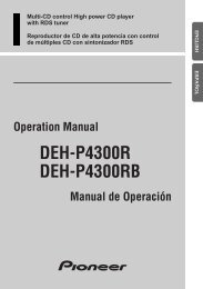
Connection Diagram<br />
Grommet<br />
Fuse (30 A)<br />
Fuse (30 A)<br />
Front side<br />
Special red battery wire [RD-223] (sold separately).<br />
After making all other connections at the amplifier,<br />
connect the battery wire terminal of the amplifier to<br />
the positive (+) terminal of the battery.<br />
Ground wire (black) [RD-223] (sold separately).<br />
Connect to metal body or chassis.<br />
Connecting wires with RCA pin<br />
plugs (sold separately).<br />
RCA input<br />
External Output<br />
If only one input plug is used, do not<br />
connect anything to RCA input jack B.<br />
Amplifier with<br />
RCA input jacks<br />
Car stereo with<br />
RCA output jacks<br />
Input Select Switch<br />
For two-channel input, slide this switch<br />
to the left. For four-channel input, slide<br />
this switch to the right.<br />
Connecting the Power Terminal<br />
• Always use the special red battery and ground<br />
wire [RD-223], which is sold separately. Connect<br />
the battery wire directly to the car battery positive<br />
terminal (+) and the ground wire to the car body.<br />
1. Pass the battery wire from the<br />
engine <strong>com</strong>partment to the interior<br />
of the vehicle.<br />
• After making all other connections to the<br />
amplifier, connect the battery wire terminal of<br />
the amplifier to the positive (+) terminal of<br />
the battery.<br />
Fuse (30 A)<br />
Fuse (30 A)<br />
Positive terminal<br />
Engine<br />
<strong>com</strong>partment<br />
Insert the O-ring rubber<br />
grommet into the vehicle<br />
body.<br />
Interior of<br />
the vehicle<br />
Drill a 14 mm<br />
hole into the<br />
vehicle body.<br />
2. Twist the battery wire, ground wire<br />
and system remote control wire.<br />
Twist<br />
4. Connect the wires to the terminal.<br />
• Fix the wires securely with the terminal<br />
screws.<br />
GND terminal<br />
Power terminal System remote<br />
control terminal<br />
Battery wire<br />
System remote<br />
control wire<br />
Ground wire<br />
Connecting the Speaker Terminals<br />
1. Expose the end of the speaker wires<br />
by about 10 mm and twist using<br />
nippers or a cutter.<br />
Twist<br />
2. Attach lugs to speaker wire ends.<br />
Lugs not supplied.<br />
• Use pliers, etc., to crimp lugs to wires.<br />
3. Connect the speaker wires to the<br />
speaker terminals.<br />
• You must attach the supplied terminal cover<br />
to the speaker output terminal.<br />
• Connect the speaker wires, passing them<br />
through the terminal cover.<br />
• Fix the speaker wires securely with the terminal<br />
screws.<br />
Terminal screw<br />
Lug<br />
10 mm<br />
Speaker wire<br />
4. Push on the terminal cover.<br />
Speaker Channel Speaker Type Power<br />
Four-channel<br />
Subwoofer<br />
Nominal input: Min. 65 W<br />
Other than subwoofer<br />
Max. input: Min. 100 W<br />
Two-channel<br />
Subwoofer<br />
Nominal input: Min. 170 W<br />
Other than subwoofer<br />
Max. input: Min. 240 W<br />
Three-channel Subwoofer Nominal input: Min. 65 W<br />
Speaker output A Other than subwoofer Max. input: Min. 100 W<br />
Three-channel Subwoofer Nominal input: Min. 170 W<br />
Speaker output B Other than subwoofer Max. input: Min. 240 W<br />
Fuse (25 A) × 2<br />
Speaker terminal<br />
See the “Connecting the<br />
Speaker wires” section<br />
for speaker connection<br />
instructions.<br />
RCA output jack<br />
Back side<br />
RCA input jack B<br />
RCA input jack A<br />
Connecting wires with RCA pin<br />
plugs (sold separately).<br />
System remote control wire (sold separately)<br />
Connect the male terminal of this wire to the system remote control<br />
terminal of the car stereo (SYSTEM REMOTE CONTROL). The female<br />
terminal can be connected to the auto-antenna relay control terminal. If the<br />
car stereo does not have a system remote control terminal, connect the<br />
male terminal to the power terminal through the ignition switch.<br />
3. Attach lugs to wire ends. Lugs not<br />
supplied.<br />
• Use pliers, etc., to crimp lugs to wires.<br />
Lug<br />
Battery wire<br />
Lug<br />
Ground wire<br />
Speaker<br />
terminal<br />
Speaker wire<br />
Terminal cover
Connecting the Unit<br />
Installation<br />
Specifications<br />
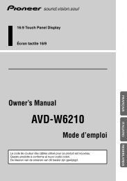
Connecting the Speaker wires<br />
The speaker output mode can be four-channel, three-channel (stereo +<br />
mono) or two-channel (stereo, mono). Connect the speaker leads to suit the<br />
mode according to the figures shown below.<br />
• When either the RCA input or the speaker input is connected, RCA output<br />
be<strong>com</strong>es functional. Do not connect both the RCA input and the speaker input at<br />
the same time.<br />
Four-channel mode<br />
(Left)<br />
Speaker input A<br />
(Right)<br />
Speaker input<br />
terminal<br />
(Right)<br />
Speaker input B<br />
(Left)<br />
Three-channel mode<br />
(Left)<br />
Speaker input A<br />
(Right)<br />
Speaker input<br />
terminal<br />
+ ≠≠+<br />
+≠≠ +<br />
+ ≠≠+<br />
+≠≠ +<br />
Input Select Switch<br />
For two-channel input, slide this switch to<br />
the left. For four-channel input, slide this<br />
switch to the right.<br />
+ ≠≠<br />
+<br />
+ ≠≠<br />
+<br />
(Right)<br />
Speaker out A<br />
(Left)<br />
Speaker output<br />
terminal<br />
(Left)<br />
Speaker out B<br />
(Right)<br />
(Right)<br />
Speaker out A<br />
(Left)<br />
Speaker output<br />
terminal<br />
Two-channel mode (stereo)<br />
(Left)<br />
Speaker input A<br />
(Right)<br />
Speaker input<br />
terminal<br />
Two-channel mode (mono)<br />
(Left)<br />
Speaker input A<br />
(Right)<br />
Speaker input<br />
terminal<br />
+ ≠≠+<br />
+ ≠≠+<br />
≠<br />
+<br />
+ ≠<br />
+<br />
+≠<br />
Input Select Switch<br />
Slide this switch to the left.<br />
≠<br />
Input Select Switch<br />
Slide this switch to the left.<br />
Speaker (Right)<br />
Speaker output<br />
terminal<br />
Speaker (Left)<br />
Speaker (Mono)<br />
Speaker output<br />
terminal<br />
Speaker (Mono)<br />
CAUTION<br />
• Do not install in:<br />
—Places where it could injure the driver or passengers<br />
if the vehicle stops suddenly.<br />
—Places where it may interfere with the driver,<br />
such as on the floor in front of the driver’s<br />
seat.<br />
• Make sure that wires are not caught in the sliding<br />
mechanism of the seats, resulting in a short-circuit.<br />
• Confirm that no parts are behind the panel when<br />
drilling a hole for installation of the amplifier.<br />
Protect all cables and important equipment such<br />
as fuel lines, brake lines and electrical wiring<br />
from damage.<br />
• Install tapping screws in such a way that the screw<br />
tip does not touch any wire. This is important to<br />
prevent wires from being cut by vibration of the<br />
car, which can result in fire.<br />
• To prevent electric shock, do not install the amplifier<br />
in places where it might <strong>com</strong>e in contact with<br />
liquids.<br />
• To ensure proper installation, use the supplied<br />
parts in the manner specified. If any parts other<br />
than the supplied ones are used, they may damage<br />
internal parts of the amplifier, or they may<br />
be<strong>com</strong>e loose causing the amplifier to shut down.<br />
To prevent malfunction<br />
• To ensure proper heat dissipation of the amplifier,<br />
be sure of the following during installation.<br />
—Allow adequate space above the amplifier for<br />
proper ventilation.<br />
—Do not cover the amplifier with a floor mat or<br />
carpet.<br />
• Do not install the amplifier near a door where it<br />
may get wet.<br />
• Do not install the amplifier on unstable places<br />
such as the spare tire board.<br />
• The best location for installation differs with the<br />
car model and installation location. Secure the<br />
amplifier at a sufficiently rigid location.<br />
• Make temporary connections first and check that<br />
the amplifier and the system operate properly.<br />
• After installing the amplifier, confirm that the<br />
spare tire, jack and tools can be easily removed.<br />
Example of installation on the floor<br />
mat or on the chassis<br />
1. Place the amplifier where it is to be<br />
installed. Insert the supplied tapping<br />
screws (4 × 18 mm) into the screw<br />
holes. Push on the screws with a<br />
screwdriver so they make marks<br />
where the installation holes are to be<br />
located.<br />
2. Drill 2.5 mm diameter holes at the<br />
point marked, and install the amplifier,<br />
either on the carpet or directly<br />
to the chassis.<br />
Tapping-screws<br />
(4 × 18 mm)<br />
Drill a 2.5 mm diameter hole<br />
Floor mat<br />
or chassis<br />
Power source .............................................................................................................. 14.4 V DC (10.8 — 15.1 V allowable)<br />
Grounding system ............................................................................................................................................ Negative type<br />
Current consumption ........................................................................................................ 32.2 A (at continuous power, 4 Ω)<br />
Average current drawn* ........................................................................................................ 10.9 A (4 Ω for four channels)<br />
15.9 A (4 Ω for two channels)<br />
Fuse .......................................................................................................................................................................... 25 A × 2<br />
Dimensions ........................................................................................................................ 270 (W) × 60 (H) × 250 (D) mm<br />
Weight ...................................................................................................................... 4.1 kg (Leads for wiring not included)<br />
Maximum power output .................................................................................................................... 100 W × 4 / 240 W × 2<br />
Continuous power output .......................................................... 50 W × 4 (at 14.4 V, 4 Ω, 20 — 20,000 Hz, 0.04% THD)<br />
120 W × 2 (at 14.4 V, 4 Ω, 20 — 20,000 Hz, 0.4% THD)<br />
60 W × 4 (at 14.4 V, 2 Ω, 20 — 20,000 Hz, 0.4% THD)<br />
Load impedance ............................................................................................................................ 4 Ω (1 — 8 Ω allowable)<br />
(Bridge connection: 2 — 8 Ω allowable)<br />
Frequency response ............................................................................................................ 10 — 50,000 Hz (+0 dB, –1 dB)<br />
Signal-to-noise ratio ...................................................................................................................... 100 dB (IEC-A network)<br />
Distortion ............................................................................................................................................ 0.005% (10 W, 1 kHz)<br />
Separation ........................................................................................................................................................ 60 dB (1 kHz)<br />
Low pass filter .................................................................................................................... Cut off frequency: 40 — 120 Hz<br />
Cut off slope: –12 dB/oct<br />
High pass filter .................................................................................................................. Cut off frequency: 40 — 120 Hz<br />
Cut off slope: –12 dB/oct<br />
Maximum input level/impedance .................................................................................... RCA: 6.5 V/22 kΩ (0.4 — 6.5 V)<br />
Speaker: 26 V/40 kΩ (1.6 — 26 V)<br />
Note:<br />
• Specifications and the design are subject to possible modification without notice<br />
due to improvements.<br />
*Average current drawn<br />
• The average current drawn is nearly the maximum current drawn by this unit<br />
when an audio signal is input. Use this value when working out total current<br />
drawn by multiple power amplifiers.<br />
(Right)<br />
Speaker input B<br />
(Left)<br />
≠<br />
+<br />
Speaker out B<br />
(Mono)<br />
+≠≠ +<br />
Input Select Switch<br />
For two-channel input, slide this switch to<br />
the left. For four-channel input, slide this<br />
switch to the right.
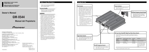
Antes de usar este producto<br />
Ajuste de esta unidad<br />
Muchas gracias por la adquisición de este<br />
producto PIONEER. Antes de tratar de<br />
operarlo, lea atentamente este manual.<br />
Control de ganancia<br />
Indicador de alimentación<br />
En caso de desperfectos<br />
Si esta unidad no funciona correctamente,<br />
póngase en contacto con su distribuidor o<br />
con el Centro de Servicio PIONEER<br />
autorizado más cercano.<br />
ADVERTENCIA<br />
• Siempre utilice el cable de batería rojo especial y<br />
el cable de tierra [RD-223], vendidos separadamente.<br />
Conecte el cable de batería directamente al<br />
terminal positivo de la batería del vehículo (+) y<br />
el cable de tierra a la carrocería del vehículo.<br />
• No toque en el amplificador con las manos<br />
mojadas. Caso contrario, usted puede llevar un<br />
choque eléctrico. Igualmente, no toque en el<br />
amplificador cuando esté mojado.<br />
• Para seguridad del tráfico y para mantener condiciones<br />
de conducción seguras, mantenga el volumen<br />
suficientemente bajo de manera que aun se<br />
pueda escuchar el sonido del tráfico normal.<br />
• Verifique las conexiones del suministro de energía<br />
y altavoces para ver si el fusible del cable de<br />
batería vendido separadamente o el fusible del<br />
amplificador se queman. Detecte la causa y solucione<br />
el problema, y reemplace el fusible con un<br />
otro del mismo tamaño y régimen.<br />
• Para evitar mal funcionamiento del amplificador y<br />
altavoces, el circuito de protección cortará la alimentación<br />
al amplificador (el sonido se detendrá)<br />
cuando se produzca una situación anormal. En tal<br />
caso, apague el sistema y verifique la conexión de<br />
la alimentación y altavoces. Detecte la causa y<br />
resuelva el problema.<br />
• Contacte a su distribuidor si no puede detectar la<br />
causa.<br />
• Para evitar choques eléctricos o cortocircuitors<br />
durante la conexión e instalación, asegúrese de<br />
desconectar el terminal negativo (–) de la batería<br />
antes de proceder.<br />
• Confirme que ninguna parte quede detrás del<br />
panel, cuando perfore un orificio para la instalación<br />
del amplificador. Asegúrese de proteger<br />
todos los cables y equipos importantes, tales <strong>com</strong>o<br />
líneas de <strong>com</strong>bustibles, líneas de frenos y el<br />
cableado eléctrico.<br />
El ajuste de los controles de ganancia A<br />
y B le ayuda a igualar la salida del<br />
equipo estéreo para automóvil al amplificador<br />
<strong>Pioneer</strong>. Normalmente, ajuste los<br />
controles de ganancia a la posición<br />
“NORMAL”. Si la potencia de salida<br />
está baja aún cuando se aumenta el volumen<br />
del equipo estéreo del automóvil,<br />
gire esos controles a la derecha. Si se<br />
produce distorsión cuando se aumenta el<br />
volumen del equipo estéreo de<br />
automóvil, gire los controles a la<br />
izquierda.<br />
• Si se usa solamente un enchufe de entrada,<br />
ajuste los controles de ganancia para las<br />
salidas de altavoz A y B a la misma posición.<br />
• Cuando se usa un estéreo de automóvil<br />
equipado con RCA (salida estándar de<br />
500 mV), ajuste a la posición NORMAL.<br />
Cuando use con un estéreo de automóvil<br />
<strong>Pioneer</strong> equipado con RCA con una salida<br />
máxima de 4 V o más, ajuste el nivel para<br />
adecuarse al nivel de salida del estéreo del<br />
automóvil.<br />
• Si se oye ruido excesivo cuando se usan los<br />
terminales de entrada de altavoz, gire el<br />
control de nivel a la izquierda.<br />
Interruptor de selección de<br />
entrada<br />
Para la entrada de dos canales, deslice<br />
este interruptor hacia la izquierda. Para<br />
la entrada de cuatro canales, deslice este<br />
interruptor hacia la derecha.<br />
Control de frecuencia de corte<br />
Si se ajusta el interruptor de selección<br />
LPF/HPF a LPF o HPF, se puede seleccionar<br />
una frecuencia de corte de 40 a<br />
120 Hz.<br />
El indicador de alimentación se ilumina<br />
cuando la unidad se encuentra activada.<br />
Interruptor BFC (Control de la<br />
frecuencia de batido)<br />
Si escucha sonidos de batido mientras<br />
está recibiendo una emisora de AM con<br />
su estéreo de automóvil, cambie el<br />
interruptor BFC usando un<br />
destornillador pequeño.<br />
Interruptor de selección LPF (Filtro de paso bajo)/HPF (Filtro de paso<br />
alto)<br />
Ajuste el interruptor de selección LPF/HPF de la manera siguiente, de acuerdo<br />
al tipo de altavoz que se encuentra conectado al conector de salida de altavoz y<br />
al sistema estéreo de automóvil:<br />
Interruptor de Gama de frecuencia de Tipo de Observaciones<br />
selección LPF/HPF audio a ser generada altavoz<br />
LPF (izquierda) * — 40 a 120 Hz Altavoz de graves Conecte a un altavoz<br />
secundario de graves secundario.<br />
OFF (central) Gama <strong>com</strong>pleta Gama <strong>com</strong>pleta<br />
HPF (derecha) * 40 a 120 Hz — Gama <strong>com</strong>pleta Utilice si desea cortar<br />
la gama de frecuencia*<br />
muy baja debido a que<br />
no es necesaria para el<br />
altavoz que está usando.<br />
* Consulte a “Control de frecuencia de corte”.
Conexión de la unidad<br />
PRECAUCION<br />
• Quite el terminal negativo (–) de la batería para<br />
evitar riesgo de cortocircuitos y daño a la unidad.<br />
• Asegure el alambrado con abrazaderas de cable o<br />
cinta adhesiva. Para proteger el alambrado,<br />
envuelva cinta adhesiva alrededor de ellos en<br />
donde contacta con partes metálicas.<br />
• No tienda cables por donde puedan calentarse, por<br />
ejemplo donde el calentador sople sobre ellos. Si<br />
la aislación se calienta, podría resultar dañada,<br />
resultando en cortocircuito a través de la carrocería<br />
del vehículo.<br />
Para prevenir de daños<br />
• No conecte a tierra (masa) el cable del altavoz<br />
directamente ni conecte un cable negativo (–) a<br />
varios altavoces.<br />
• Esta unidad es para vehículos con una batería de<br />
12 voltios y terminal negativo a tierra. Antes de<br />
instalar en un vehículo de recreación, camión u<br />
ómnibus, verifique el voltaje de la batería.<br />
• Si el sistema estereofónico del coche está funcionando<br />
por un largo período de tiempo mientras el<br />
motor permanece inactivo o en marcha al ralentí,<br />
la batería puede agotarse. Apague el estéreo de<br />
automóvil cuando el motor se encuentre funcionando<br />
en marcha al ralenté o permanece in activo.<br />
• Si el cable del control remoto del sistema del<br />
amplificador se conecta al terminal de alimentación<br />
a través del interruptor de encendido<br />
(12 V de CC), el amplificador estará siempre activado<br />
cuando el encendido está activado, sin considerar<br />
de si el estéreo de automóvil se encuentra<br />
activado o desactivado. Debido a esto, la batería<br />
puede agotarse si deja el motor funcionando en<br />
marcha al ralentí o permanece inactivo.<br />
• Asegúrese que los alambres no interfieran con<br />
partes móviles del vehículo <strong>com</strong>o la palanca de<br />
cambios, el freno de mano o el mecanismo de<br />
deslizamiento de los asientos.<br />
• No corte ningún cable. De otra manera, el circuito<br />
de protección podría no funcionar cuando debiera.<br />
• Nunca alimente otro equipo cortando la aislación<br />
del cable de alimentación y conectándolo al cable.<br />
La capacidad de corriente del cable será excedida,<br />
causando sobrecalentamiento.<br />
Canal de altavoces Tipo de altavoz Alimentación<br />
Cuatro canales<br />
Dos canales<br />
Altavoz de graves secundario<br />
Diferente a un altavoz de graves secundario<br />
Altavoz de graves secundario<br />
Diferente a un altavoz de graves secundario<br />
• Los altavoces a ser conectados al amplificador<br />
deben estar conforme con las normas listadas<br />
debajo. Si no cumplen con las normas, pueden<br />
<strong>com</strong>bustionar, emitir humos o dañarse. El impedimiento<br />
altavoz debe estar de 1 a 8 ohms, pero<br />
en caso de que dos canales y otros puentes<br />
contecten, el impedimiento de altavoz debe estar<br />
de 2 a 8 ohms.<br />
• Instale y coloque el cable de batería vendido separadamente<br />
lo más alejado posible de los cables de<br />
los altavoces. Instale y coloque el cable de batería<br />
y cable de tierra vendidos separadamente, los<br />
cables de los altavoces, y el amplificador lo más<br />
alejados posible de la antena, cable de antena y<br />
sintonizador.<br />
• Los cables para esta unidad y aquéllas para las<br />
unidades pueden ser de colores diferentes aun si<br />
tienen la misma función. Cuando se conecta esta<br />
unidad a otra, refiérase a los manuales de instalación<br />
de ambas unidades y conecte los cables<br />
que tienen la misma función.<br />
Entrada nominal: 65 W mín.<br />
Entrada máxima: 100 W mín.<br />
Entrada nominal: 170 W mín.<br />
Entrada máxima: 240 W mín.<br />
Salida de altavoz A Altavoz de graves secundario Entrada nominal: 65 W mín.<br />
de tres canales Diferente a un altavoz de graves secundario Entrada máxima: 100 W mín.<br />
Salida de altavoz B Altavoz de graves secundario Entrada nominal: 170 W mín.<br />
de tres canales Diferente a un altavoz de graves secundario Entrada máxima: 240 W mín.<br />
Diagrama de conexión<br />
Ojal<br />
Fusible (25 A) × 2<br />
Fusible (30 A)<br />
Fusible (30 A)<br />
Terminal de altavoz<br />
Vea la sección “Conexión de<br />
los cables de altavoces” para<br />
las instrucciones de conexión<br />
del altavoz.<br />
Cable de batería rojo especial [RD-223]<br />
(en venta por separado).<br />
Después de realizar todas las conexiones al amplificador,<br />
conecte el terminal del conductor de batería del amplificador<br />
al terminal positivo (+) de la batería.<br />
Cable de puesta a tierra (negro) [RD-223]<br />
(en venta por separado).<br />
Conecte a una carrocería metálica o chasis.<br />
Conexión de cables con los enchufes de<br />
conector RCA (en venta por separado).<br />
Lado delantero<br />
Entrada RCA<br />
Salida externa<br />
Si se usa solamente un enchufe de<br />
entrada, no conecte nada a la toma de<br />
entrada RCA B.<br />
Tomas de conector<br />
de salida RCA<br />
Lado trasero<br />
Amplificador con<br />
tomas con conector<br />
de entrada RCA<br />
Estéreo de automóvil<br />
con tomas con<br />
conector de salida<br />
RCA<br />
Interruptor de selección de entrada<br />
Para la entrada de dos canales, deslice<br />
este interruptor hacia la izquierda. Para<br />
la entrada de cuatro canales, deslice<br />
este interruptor hacia la derecha.<br />
Tomas de conector de<br />
entrada RCA B<br />
Tomas de conector de entrada RCA A<br />
Conexión de cables con los enchufes de<br />
conector RCA (en venta por separado).<br />
Cable del control remoto del sistema (en venta por separado)<br />
Conecte el terminal macho de este hilo al terminal de control remoto<br />
de sistema del equipo estéreo para automóvil (SYSTEM REMOTE<br />
CONTROL). El terminal hembra puede ser conectado al terminal de<br />
control del relé de antena. Si el estéreo de automóvil no tiene un<br />
terminal de control remoto del sistema, conecte el terminal macho al<br />
terminal de alimentación a través del interruptor de encendido.<br />
Conexión del terminal de<br />
alimentación<br />
• Siempre utilice el cable de batería rojo especial y<br />
el cable de tierra [RD-223], vendidos separadamente.<br />
Conecte el cable de batería directamente al<br />
terminal positivo de la batería del vehículo (+) y<br />
el cable de tierra a la carrocería del vehículo.<br />
1. Pase el cable de batería desde el<br />
<strong>com</strong>partimiento del motor al interior<br />
del vehículo.<br />
• Luego de hacer todas las otras conexiones al<br />
amplificador, conecte el terminal del conductor<br />
de batería del amplificador al terminal<br />
positivo (+) de la bateria.<br />
Fusible (30 A) Compartimiento<br />
del Interior del<br />
motor vehículo<br />
Fusible (30 A)<br />
Terminal positivo<br />
Inserte el ojal de caucho<br />
de la junta tórica en la<br />
corrocería del vehículo.<br />
Perfore un orificio<br />
de 14 mm en<br />
la carrocería del<br />
vehículo.<br />
2. Tuerza el cable de batería, cable de<br />
puesta a tierra y cable de control<br />
remoto del sistema.<br />
3. Fije las orejetas a los extremos de<br />
los cables. Orejetas no suministrados.<br />
• Utilice alicates, etc. para plegar las orejetas a<br />
los cables.<br />
Orejeta<br />
Cable de batería<br />
Orejeta<br />
Tuérzala<br />
Cable de<br />
puesta a tierra<br />
4. Conecte los cables al terminal.<br />
• Fijar los cables firmemente utilizando los<br />
tornillos para terminales.<br />
Terminal<br />
POWER<br />
Cable de batería<br />
Terminal GND<br />
Terminal de control<br />
remoto del sistema<br />
Cable del control<br />
remoto del sistema<br />
Cable de puesta<br />
a tierra<br />
Conexión del terminal de altavoz<br />
1. Desnude la extremidad de los cables<br />
de altavoces por aproximadamente<br />
10 mm y tuérzala utilizando alicates<br />
o una tajadera.<br />
10 mm<br />
2. Fije las orejetas a los extremos de<br />
los cables de altavoz. Orejetas no<br />
suministrados.<br />
• Utilice alicates, etc. para plegar las orejetas a<br />
los cables.<br />
3. Conecte los cables de altavoz al terminal<br />
de altavoz.<br />
• La cubierta para terminales suministrada se<br />
debe fijar al terminal de salida de altavoz.<br />
• Conecte los hilos de altavoz, pasándolos a<br />
través de la cubierta de los terminales.<br />
• Fije los cables firmemente utilizando los<br />
tornillos para terminales.<br />
Torrillo de terminal<br />
Terminal de<br />
altavoz<br />
Cable de<br />
altavoz<br />
Orejeta<br />
Tuérzala<br />
Cable de altavoz<br />
Cubierta de<br />
los terminales<br />
4. Empuje la cubierta de los<br />
terminales.
Conexión de la unidad<br />
Instalación<br />
Especificaciones<br />
Conexión de los cables de altavoces<br />
El modo de salida de altavoz puede ser de cuatro canales, tres canales<br />
(estéreo + mono) o dos canales (estéreo, mono). Conecte los cables de<br />
altavoz para ajustarse al modo según los diagramas mostrados abajo.<br />
• Cuando la entrada de RCA o la entrada de altavoz esta conectada, la salida de<br />
RCA viene funcionada. No poder conectar tanto la entrada de RCA y la entrada<br />
de altavoz al mismo tiempo.<br />
Modo de cuatro canales<br />
(Izquierdo)<br />
Entrada de altavoz A<br />
(Derecho)<br />
Terminal de entrada<br />
de altavoz<br />
(Derecho)<br />
Entrada de altavoz B<br />
(Izquierdo)<br />
Modo de tres canales<br />
(Izquierdo)<br />
Entrada de altavoz A<br />
(Derecho)<br />
Terminal de entrada<br />
de altavoz<br />
(Derecho)<br />
Entrada de altavoz B<br />
(Izquierdo)<br />
+ ≠≠+<br />
+≠≠ +<br />
+ ≠≠+<br />
+≠≠ +<br />
+≠≠ +<br />
Interruptor de selección de entrada<br />
Para la entrada de dos canales, deslice este interruptor<br />
hacia la izquierda. Para la entrada de cuatro<br />
canales, deslice este interruptor hacia la derecha.<br />
Interruptor de selección de entrada<br />
Para la entrada de dos canales, deslice este interruptor<br />
hacia la izquierda. Para la entrada de cuatro<br />
canales, deslice este interruptor hacia la derecha.<br />
≠<br />
+<br />
+ ≠≠<br />
+<br />
+ ≠≠<br />
+<br />
(Derecho)<br />
Salida de altavoz A<br />
(Izquierdo)<br />
Terminal de salida<br />
de altavoz<br />
(Izquierdo)<br />
Salida de altavoz B<br />
(Derecho)<br />
(Derecho)<br />
Salida de altavoz A<br />
(Izquierdo)<br />
Terminal de salida<br />
de altavoz<br />
Salida de altavoz B<br />
(Mono)<br />
Modo de dos canales (estéreo)<br />
(Izquierdo)<br />
Entrada de altavoz A<br />
(Derecho)<br />
Terminal de entrada<br />
de altavoz<br />
Modo de dos canales (mono)<br />
(Izquierdo)<br />
Entrada de altavoz A<br />
(Derecho)<br />
Terminal de entrada<br />
de altavoz<br />
+ ≠≠+<br />
+ ≠≠+<br />
+<br />
+<br />
+≠<br />
Interruptor de selección de entrada<br />
Deslice este interruptor hacia la izquierda.<br />
+ ≠<br />
Interruptor de selección de entrada<br />
Deslice este interruptor hacia la izquierda.<br />
≠<br />
≠<br />
Altavoz (Derecho)<br />
Terminal de salida<br />
de altavoz<br />
Altavoz (Izquierdo)<br />
Altavoz (Mono)<br />
Terminal de salida<br />
de altavoz<br />
Altavoz (Mono)<br />
PRECAUCION<br />
• No lo instale en:<br />
—Donde podría lesionar al conductor o a los<br />
pasajeros si se detiene el vehículo bruscamente.<br />
—Donde podría interferir con el conductor,<br />
<strong>com</strong>o por ejemplo en el piso en frente al<br />
asiento del conductor.<br />
• Asegúrese que los cables no se enganchen en el<br />
mecanismo deslizante de los asientos, resultando<br />
en cortocircuito.<br />
• Confirme que ninguna parte quede detrás del<br />
panel, cuando perfore un orificio para la instalación<br />
del amplificador. Asegúrese de proteger<br />
todos los cables y equipos importantes, tales <strong>com</strong>o<br />
líneas de <strong>com</strong>bustibles, líneas de frenos y el<br />
cableado eléctrico.<br />
• Instale los tornillos de conexión de manera tal que<br />
la punta del tornillo no toque ningún cable. Esto<br />
es importante para evitar que los cables se corten<br />
por vibración del automóvil, lo que podría causar<br />
un incendio.<br />
• Para evitar choques eléctricos, no instale el amplificador<br />
en donde pueda entrar en contacto con<br />
líquidos.<br />
• Para asegurar una instalación apropiada, utilice las<br />
partes suministradas de la manera especificada. Si<br />
se utiliza cualquier otra parte que no sean las suministradas,<br />
puede dañarse las partes internas del<br />
amplificador, o pueden aflojarse y el amplificador<br />
puede dejar de funcionar.<br />
Para evitar fallas del funcionamiento<br />
• Para asegurar la disipación de calor apropriada del<br />
amplificador, cuide de lo siguiente durante la<br />
instalación.<br />
—Permita un espacio adecuado en la parte superior<br />
del amplificador para una ventilación<br />
apropiada.<br />
—No cubra el amplificador con la cubierta de<br />
piso o alfombra.<br />
• No instale el amplificador cerca de una puerta en<br />
donde puede ser mojado por la lluvia.<br />
• No instale el amplificador sobre superficies inestables<br />
<strong>com</strong>o el tablero del neumático de repuesto.<br />
• Confirme que ninguna parte quede detrás del<br />
panel, cuando perfore un orificio para la instalación<br />
del amplificador. Asegúrese de proteger<br />
todos los cables y equipos importantes, tales <strong>com</strong>o<br />
líneas de <strong>com</strong>bustibles, líneas de frenos y el<br />
cableado eléctrico.<br />
• Realice primero conexiones provisorias y <strong>com</strong>pruebe<br />
que el amplificador y el sistema operan<br />
adecuadamente.<br />
• Para asegurar una instalación apropiada, utilice las<br />
partes suministradas de la manera especificada. Si<br />
se utiliza cualquier otra parte que no sean las suministradas,<br />
puede dañarse las partes internas del<br />
amplificador, o pueden aflojarse y el amplificador<br />
puede dejar de funcionar.<br />
Ejemplo de instalación en la<br />
alfombra del piso o en el chasis<br />
1. Ubique el amplificador en la posición<br />
en donde va a ser instalado.<br />
Inserte los tornillos autoterrajantes<br />
suministrados (4 × 18 mm) en los<br />
orificios de los tornillos. Presione los<br />
tornillos con un destornillador de<br />
modo que puedan dejar puntos marcados<br />
de la posición en donde irán<br />
los orificios para la instalación.<br />
2. Perfore orificios de 2,5 mm de<br />
diámetro en el punto marcado, e<br />
instale el amplificador, ya sea en la<br />
alfombra o directamente en el<br />
chasis.<br />
Perfore un orificio de<br />
2,5 mm de diámetro<br />
Tornillos autoterrajantes<br />
(4 × 18 mm)<br />
Alfombra<br />
del piso o<br />
chasis<br />
Alimentación ............................................................................................................ 14,4 V CC (10,8 — 15,1 V permisible)<br />
Sistema de puesta a tierra .................................................................................................................................. Tipo negativo<br />
Consumo de corriente .......................................................................................................... 32,2 A (potencia continua, 4 Ω)<br />
Consumo de corriente promedio* ...................................................................................... 10,9 A (4 Ω para cuatro canales)<br />
15,9 A (4 Ω para dos canales)<br />
Fusible ........................................................................................................................................................................ 25 A × 2<br />
Dimensiones .................................................................................................................... 270 (An) × 60 (Al) × 250 (Pr) mm<br />
Peso .............................................................................................. 4,1 kg (No se incluyen los conductores para el cableado)<br />
Potencia de salida máxima ................................................................................................................ 100 W × 4 / 240 W × 2<br />
Potencia de salida continua ........................................................ 50 W × 4 (en 14,4 V, 4 Ω, 20 — 20.000 Hz, 0,04% THD)<br />
120 W × 2 (en 14,4 V, 4 Ω, 20 — 20.000 Hz, 0,4% THD)<br />
60 W × 4 (en 14,4 V, 2 Ω, 20 — 20.000 Hz, 0,4% THD)<br />
Impedancia de carga .................................................................................................................... 4 Ω (1 — 8 Ω permisible)<br />
(Acoplamiento en derivación: 2 — 8 Ω permisible)<br />
Respuesta de frecuencia ...................................................................................................... 10 — 50.000 Hz (+0 dB, –1 dB)<br />
Relación de señal a ruido ...................................................................................................................... 100 dB (IEC-Red A)<br />
Distorsión ............................................................................................................................................ 0,005% (10 W, 1 kHz)<br />
Separación de canales ...................................................................................................................................... 60 dB (1 kHz)<br />
Filtro de paso bajo............................................................................................................ Frecuencia de corte: 40 — 120 Hz<br />
Pendiente de corte: –12 dB/oct<br />
Filtro de paso alto ............................................................................................................ Frecuencia de corte: 40 — 120 Hz<br />
Pendiente de corte: –12 dB/oct<br />
Impedancia/nivel de entrada máxima ............................................................................ RCA: 6,5 V/22 kΩ (0,4 — 6,5 V)<br />
Altavoz: 26 V/40 kΩ (1,6 — 26 V)<br />
Nota:<br />
• Las especificaciones y el diseño están sujetos a posibles modificaciones sin previo<br />
aviso debido a mejoramientos.<br />
*Consumo de corriente promedio<br />
• El consumo de corriente promedio es casi el consumo de corriente máximo de esta<br />
unidad, cuando se ingresa una señal de audio. Utilice este valor cuando tenga que<br />
trabajar con la corriente total consumida por múltiples amplificadores de potencia.