
You also want an ePaper? Increase the reach of your titles
YUMPU automatically turns print PDFs into web optimized ePapers that Google loves.
Installation English Installation English<br />
CD RECEIVER<br />
RADIO CD<br />
CD PLAYER<br />
<strong>DEH</strong>-<strong>4150SD</strong><br />
<strong>DEH</strong>-<strong>3100UB</strong><br />
Note<br />
• Check all connections and systems before final<br />
installation.<br />
• Do not use unauthorized parts. The use of<br />
unauthorized parts may cause malfunctions.<br />
• Consult with your dealer if installation requires<br />
drilling of holes or other modifications of the<br />
vehicle.<br />
• Do not install this unit where:<br />
— it may interfere with operation of the vehicle.<br />
— it may cause injury to a passenger as a result<br />
of a sudden stop.<br />
• The semiconductor laser will be damaged if it<br />
overheats. Install this unit away from hot places<br />
such as near the heater outlet.<br />
• Optimum performance is obtained when the unit is<br />
installed at an angle of less than 60°.<br />
60°<br />
• When installing, to ensure proper heat dispersal<br />
when using this unit, make sure you leave ample<br />
space behind the rear panel and wrap any loose<br />
cables so they are not blocking the vents.<br />
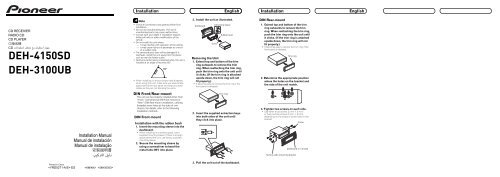
3. Install the unit as illustrated.<br />
Dashboard<br />
53<br />
182<br />
Screw<br />
Mounting sleeve<br />
Rubber bush<br />
Removing the Unit<br />
1. Extend top and bottom of the trim<br />
ring outwards to remove the trim<br />
ring. When reattaching the trim ring,<br />
push the trim ring onto the unit until<br />
it clicks. (If the trim ring is attached<br />
upside down, the trim ring will not<br />
fit properly.)<br />
• It be<strong>com</strong>es easy to remove the trim ring if the<br />
front panel is released.<br />
DIN Rear-mount<br />
1. Extend top and bottom of the trim<br />
ring outwards to remove the trim<br />
ring. When reattaching the trim ring,<br />
push the trim ring onto the unit until<br />
it clicks. (If the trim ring is attached<br />
upside down, the trim ring will not<br />
fit properly.)<br />
• It be<strong>com</strong>es easy to remove the trim ring if the<br />
front panel is released.<br />
Trim ring<br />
2. Determine the appropriate position<br />
where the holes on the bracket and<br />
the side of the unit match.<br />
Installation Manual<br />
Manual de instalación<br />
Manual de instalação<br />
DIN Front/Rear-mount<br />
This unit can be properly installed either from<br />
“Front” (conventional DIN Front-mount) or<br />
“Rear” (DIN Rear-mount installation, utilizing<br />
threaded screw holes at the sides of unit<br />
chassis). For details, refer to the following<br />
installation methods.<br />
DIN Front-mount<br />
Installation with the rubber bush<br />
1. Insert the mounting sleeve into the<br />
dashboard.<br />
• When installing in a shallow space, use a<br />
supplied mounting sleeve. If there is enough<br />
space behind the unit, use factory supplied<br />
mounting sleeve.<br />
2. Secure the mounting sleeve by<br />
using a screwdriver to bend the<br />
metal tabs (90°) into place.<br />
Trim ring<br />
2. Insert the supplied extraction keys<br />
into both sides of the unit until<br />
they click into place.<br />
3. Tighten two screws on each side.<br />
• Use either truss screws (5 mm × 8 mm)<br />
or flush surface screws (5 mm × 9 mm),<br />
depending on the shape of screw holes in the<br />
bracket.<br />
Screw<br />
Dashboard or Console<br />
Factory radio mounting bracket<br />
Printed in China<br />
ES<br />
<br />
3. Pull the unit out of the dashboard.
1. This product<br />
2. Rear output or<br />
subwoofer output<br />
3. Antenna jack<br />
4. Front output<br />
5. Fuse (10 A)<br />
7. Yellow<br />
Connect to the constant 12 V supply terminal.<br />
6. Wired remote input<br />
Hard-wired remote control<br />
adaptor can be connected<br />
(sold separately).<br />
23. To rear output or<br />
subwoofer output<br />
24. To front output<br />
25. Connect with RCA cables<br />
(sold separately)<br />
26. Power amp<br />
(sold separately)<br />
26. Power amp<br />
(sold separately)<br />
1. This product<br />
31. Subwoofer output<br />
3. Antenna jack<br />
4. Front output<br />
5. Fuse (10 A)<br />
6. Wired remote input<br />
Hard-wired remote control<br />
adaptor can be connected<br />
(sold separately).<br />
27. Blue/white<br />
Connect to system control<br />
terminal of the power amp or<br />
auto-antenna relay control<br />
terminal (max. 300 mA 12 V DC).<br />
8. Red<br />
Connect to terminal controlled by<br />
ignition switch (12 V DC).<br />
9. Black (chassis ground)<br />
Connect to a clean, paint-free metal location.<br />
10. White 12. Gray<br />
<br />
<br />
14. Front speaker<br />
14. Front speaker<br />
<br />
<br />
11. White/black 13. Gray/black<br />
15. Left 16. Right<br />
17. Green 19. Violet<br />
<br />
<br />
21. Rear speaker<br />
21. Rear speaker<br />
<br />
<br />
18. Green/black 20. Violet/black<br />
22. With a 2 speaker system, do not connect<br />
anything to the speaker leads that are<br />
not connected to speakers.<br />
28. System remote control<br />
27. Blue/white<br />
Connect to system control terminal of the<br />
power amp or auto-antenna relay control<br />
terminal (max. 300 mA 12 V DC).<br />
<br />
<br />
14. Front speaker 14. Front speaker<br />
<br />
<br />
30. Rear speaker<br />
or subwoofer<br />
<br />
<br />
29. Perform these connections<br />
when using the optional<br />
amplifier.<br />
<br />
<br />
30. Rear speaker<br />
or subwoofer<br />
7. Yellow<br />
Connect to the constant 12 V supply terminal.<br />
8. Red<br />
Connect to terminal controlled by<br />
ignition switch (12 V DC).<br />
9. Black (chassis ground)<br />
Connect to a clean, paint-free metal location.<br />
32. Note<br />
Change the initial setting of this unit.<br />
The subwoofer output of this unit is monaural.<br />
10. White 12. Gray<br />
<br />
<br />
14. Front speaker<br />
14. Front speaker<br />
<br />
<br />
11. White/black 13. Gray/black<br />
15. Left 16. Right<br />
33. Subwoofer (4 Ω)<br />
<br />
<br />
17. Green 19. Violet<br />
18. Green/black 20. Violet/black<br />
34. When using a subwoofer of 70 W (2 Ω), be sure to connect<br />
with Violet and Violet/black leads of this unit.<br />
Do not connect anything with Green and Green/black leads.<br />
17. Green 19. Violet<br />
35. Not used.<br />
18. Green/black 20. Violet/black<br />
<br />
<br />
<br />
<br />
33. Subwoofer (4 Ω)<br />
36. Subwoofer<br />
(4 Ω) 2<br />
Fig. 1<br />
<br />
Fig. 2
Instalación<br />
Español<br />
Instalación<br />
Español<br />
Instalação<br />
Português (B)<br />
Instalação<br />
Português (B)<br />
Nota<br />
• Verifique todas las conexiones y sistemas antes<br />
de la instalación final.<br />
• No utilice piezas no autorizadas. El uso de<br />
piezas no autorizadas puede causar un fallo de<br />
funcionamiento.<br />
• Consulte su revendedor si se requiere taladrar<br />
agujeros o hacer otras modificaciones del<br />
vehículo para la instalación.<br />
• No instale esta unidad donde:<br />
— pueda interferir con la operación del vehículo.<br />
— pueda causar lesiones a un pasajero en el<br />
caso de una parada brusca.<br />
• El láser semiconductor se dañará si se<br />
sobrecalienta. Instale esta unidad alejada de<br />
lugares calientes <strong>com</strong>o cerca de la salida del<br />
calentador.<br />
• Se obtiene el rendimiento óptimo cuando se<br />
instala la unidad en un ángulo inferior a 60°.<br />
60°<br />
• Cuando instale, para asegurar la dispersión<br />
apropiada del calor cuando utilice la unidad,<br />
asegúrese de dejar un amplio espacio detrás del<br />
panel trasero y de enrollar cualesquiera cables<br />
sueltos de modo que no bloqueen las aberturas<br />
de ventilación.<br />
Montaje delantero/trasero DIN<br />
Se puede instalar esta unidad apropiadamente<br />
mediante el montaje “delantero” (montaje<br />
delantero DIN convencional) o montaje<br />
“trasero” (montaje trasero DIN utilizando<br />
los agujeros de tornillo roscados en los lados<br />
del bastidor de la unidad). Para los detalles,<br />
consulte los siguientes métodos de instalación.<br />
Montaje delantero DIN<br />
Instalación con el buje de caucho<br />
1. Inserte el manguito de montaje en<br />
el tablero de instrumentos.<br />
• Cuando instale en un lugar poco profundo,<br />
utilice el manguito de montaje suministrado.<br />
Si hay espacio suficiente detrás de la unidad,<br />
utilice el manguito de montaje suministrado<br />
de fábrica.<br />
2. Fije el manguito de montaje<br />
utilizando un destornillador para<br />
doblar las lengüetas de metal (90°)<br />
en posición.<br />
3. Instale la unidad <strong>com</strong>o se muestra.<br />
Tablero de<br />
Manguito de montaje<br />
instrumentos<br />
53<br />
182<br />
Tornillo<br />
Buje de caucho<br />
Extracción de la unidad<br />
1. Extienda las partes superior e<br />
inferior del anillo de <strong>com</strong>pensación<br />
hacia fuera para extraer el anillo de<br />
<strong>com</strong>pensación. Cuando reinstale<br />
el anillo de <strong>com</strong>pensación, empuje<br />
el anillo de <strong>com</strong>pensación en la<br />
unidad hasta que encaje con un<br />
“clic”. (Si se instala el anillo de<br />
<strong>com</strong>pensación invertido, puede que<br />
el anillo de <strong>com</strong>pensación no se<br />
encaje correctamente.)<br />
• Se hace más fácil quitar el anillo de<br />
<strong>com</strong>pensación si se suelta el panel delantero.<br />
Anillo de<br />
<strong>com</strong>pensación<br />
2. Inserte las llaves de extracción<br />
suministradas en ambos lados de<br />
la unidad hasta que se enganchen<br />
en posición.<br />
3. Tire de la unidad del tablero de<br />
instrumentos.<br />
Montaje trasero DIN<br />
1. Extienda las partes superior e<br />
inferior del anillo de <strong>com</strong>pensación<br />
hacia fuera para extraer el anillo de<br />
<strong>com</strong>pensación. Cuando reinstale<br />
el anillo de <strong>com</strong>pensación, empuje<br />
el anillo de <strong>com</strong>pensación en la<br />
unidad hasta que encaje con un<br />
“clic”. (Si se instala el anillo de<br />
<strong>com</strong>pensación invertido, puede que<br />
el anillo de <strong>com</strong>pensación no se<br />
encaje correctamente.)<br />
• Se hace más fácil quitar el anillo de<br />
<strong>com</strong>pensación si se suelta el panel delantero.<br />
Anillo de<br />
<strong>com</strong>pensación<br />
2. Determine la posición apropiada<br />
donde los agujeros en la ménsula y<br />
el lado de la unidad se emparejan.<br />
3. Apriete los dos tornillos en cada<br />
lado.<br />
• Utilice tornillos con cabeza ovalada (5 mm ×<br />
8 mm) o tornillos de cabeza embutida (5 mm<br />
× 9 mm), dependiendo de la forma de los<br />
agujeros de tornillo en la ménsula.<br />
Tornillo<br />
Ménsula de montaje<br />
de radio de fábrica<br />
Tablero de instrumentos<br />
o consola<br />
Nota<br />
• Verifique todas as conexões e sistemas antes da<br />
instalação final.<br />
• Não utilize peças não autorizadas. O uso de<br />
peças não autorizadas pode causar um mau<br />
funcionamento.<br />
• Consulte o seu revendedor se for necessário fazer<br />
furos ou outras modificações no veículo para a<br />
instalação.<br />
• Não instale este aparelho onde o mesmo:<br />
— possa interferir <strong>com</strong> a operação do veículo.<br />
— possa causar ferimentos a um passageiro no<br />
caso de uma parada brusca.<br />
• O laser semicondutor sofrerá danos se for<br />
sobreaquecido. Instale este aparelho longe<br />
de lugares quentes <strong>com</strong>o perto da saída do<br />
aquecedor.<br />
• O desempenho ótimo será obtido quando o<br />
aparelho for instalado em um ângulo inferior a 60°.<br />
60°<br />
• Quando instalar, para assegurar a dispersão<br />
apropriada do calor ao utilizar o aparelho,<br />
certifique-se de deixar um amplo espaço atrás<br />
do painel traseiro e de enrolar quaisquer cabos<br />
soltos de modo que não bloqueiem as aberturas<br />
de ventilação.<br />
Montagem frontal/traseira DIN<br />
Este aparelho pode ser instalado<br />
apropriadamente através de uma montagem<br />
“frontal” (montagem frontal DIN convencional)<br />
ou de uma montagem “traseira” (montagem<br />
traseira DIN utilizando os furos de parafuso<br />
rosqueados nos lados do chassi do aparelho).<br />
Para maiores detalhes, consulte os seguintes<br />
métodos de instalação.<br />
Montagem frontal DIN<br />
Instalação <strong>com</strong> a bucha de<br />
borracha<br />
1. Insira a manga de montagem no<br />
painel de instrumentos.<br />
• Quando instalar em um lugar pouco profundo,<br />
utilize a manga de montagem fornecida. Se<br />
houver espaço suficiente atrás do aparelho,<br />
utilize a manga de montagem fornecida de<br />
fábrica.<br />
2. Fixe a manga de montagem<br />
utilizando uma chave de fenda para<br />
dobrar as lingüetas de metal (90°)<br />
em posição.<br />
3. Instale o aparelho <strong>com</strong>o mostrado.<br />
Painel de<br />
Manga de montagem<br />
instrumentos<br />
53<br />
182<br />
Parafuso<br />
Bucha de borracha<br />
Remoção do aparelho<br />
1. Estenda as partes superior e inferior<br />
do anel de <strong>com</strong>pensação para fora<br />
para retirar o anel de <strong>com</strong>pensação.<br />
Ao reinstalar o anel de <strong>com</strong>pensação,<br />
empurre o anel de <strong>com</strong>pensação<br />
no <strong>com</strong>ponente até que se encaixe<br />
<strong>com</strong> um estalido. (Se o anel de<br />
<strong>com</strong>pensação for instalado de cabeça<br />
para baixo, o anel de <strong>com</strong>pensação<br />
não se encaixará corretamente.)<br />
• Fica mais fácil retirar o anel de <strong>com</strong>pensação<br />
se o painel frontal for solto.<br />
Anel de <strong>com</strong>pensação<br />
2. Insira as chaves de extração<br />
fornecidas em ambos lados do<br />
aparelho até que se encaixem em<br />
posição.<br />
3. Puxe o aparelho desde o painel de<br />
instrumentos.<br />
Montagem traseira DIN<br />
1. Estenda as partes superior e<br />
inferior do anel de <strong>com</strong>pensação<br />
para fora para retirar o anel de<br />
<strong>com</strong>pensação. Ao reinstalar o<br />
anel de <strong>com</strong>pensação, empurre<br />
o anel de <strong>com</strong>pensação no<br />
<strong>com</strong>ponente até que se encaixe<br />
<strong>com</strong> um estalido. (Se o anel de<br />
<strong>com</strong>pensação for instalado de<br />
cabeça para baixo, o anel de<br />
<strong>com</strong>pensação não se encaixará<br />
corretamente.)<br />
• Fica mais fácil retirar o anel de <strong>com</strong>pensação<br />
se o painel frontal for solto.<br />
Anel de <strong>com</strong>pensação<br />
2. Determine a posição apropriada<br />
onde os furos no suporte e o lado<br />
do aparelho se emparelham.<br />
3. Aperte dois parafusos em cada<br />
lado.<br />
• Utilize parafusos de cabeça oval (5 mm ×<br />
8 mm) ou parafusos de cabeça chata (5 mm<br />
× 9 mm), dependendo da forma dos furos de<br />
parafuso no suporte.<br />
Parafuso<br />
Painel de instrumentos ou console<br />
Suporte de montagem de rádio de fábrica
60°<br />
<br />
<br />
53<br />
182
Connecting the units<br />
English<br />
Connecting the units<br />
English<br />
Conexión de las unidades Español Conexión de las unidades Español<br />
Note<br />
• When this unit is installed in a vehicle without<br />
ACC (accessory) position on the ignition switch,<br />
red cable must be wired to the terminal that can<br />
detect the operation of the ignition key. Otherwise,<br />
battery drain may result.<br />
OFF<br />
ACC<br />
ON<br />
START<br />
<br />
ACC position No ACC position<br />
<br />
• Use this unit in other than the following<br />
conditions could result in fire or malfunction.<br />
— Vehicles with a 12-volt battery and negative<br />
grounding.<br />
— Speakers with 50 W (output value) and 4 ohm<br />
to 8 ohm (impedance value).<br />
• To prevent short-circuit, overheating or<br />
malfunction, be sure to follow the directions<br />
below.<br />
— Disconnect the negative terminal of the<br />
battery before installation.<br />
— Secure the wiring with cable clamps or<br />
adhesive tape. To protect the wiring, wrap<br />
adhesive tape around them where they lie<br />
against metal parts.<br />
— Place all cables away from moving parts, such<br />
as gear shift and seat rails.<br />
— Place all cables away from hot places, such as<br />
near the heater outlet.<br />
— Do not pass the yellow cable through a hole<br />
into the engine <strong>com</strong>partment to connect to a<br />
battery.<br />
— Cover any disconnected cable connectors with<br />
insulating tape.<br />
— Do not shorten any cables.<br />
— Never cut the insulation of the power cable of<br />
this unit in order to share the power to other<br />
equipment. Current capacity of the cable is<br />
limited.<br />
— Use a fuse of the rating prescribed.<br />
— Never wire the speaker negative cable directly<br />
to ground.<br />
— Never band together multiple speaker’s<br />
negative cables.<br />
OFF<br />
ON<br />
START<br />
• Control signal is output through blue/white cable<br />
when this unit is powered on. Connect it to an<br />
external power amp’s system remote control or<br />
the vehicle’s auto-antenna relay control terminal<br />
(max. 300 mA, 12 V DC). If the vehicle is equipped<br />
with a glass antenna, connect it to the antenna<br />
booster power supply terminal.<br />
• Never connect blue/white cable to external power<br />
amp’s power terminal. Also, never connect<br />
it to the power terminal of the auto antenna.<br />
Otherwise, battery drain or malfunction may<br />
result.<br />
• Black cable is ground. This cable and other<br />
product’s ground cable (especially, high-current<br />
products such as power amp) must be wired<br />
separately. Otherwise, fire or malfunction may<br />
result if they are accidentally detached.<br />
Connection Diagram<br />
When not connecting a rear speaker<br />
lead to a subwoofer (Fig. 1)<br />
When using a Subwoofer without<br />
using the optional amplifier (Fig. 2)<br />
1. This product<br />
2. Rear output or subwoofer output<br />
3. Antenna jack<br />
4. Front output<br />
5. Fuse (10 A)<br />
6. Wired remote input<br />
Hard-wired remote control adaptor can be<br />
connected (sold separately).<br />
7. Yellow<br />
Connect to the constant 12 V supply terminal.<br />
8. Red<br />
Connect to terminal controlled by ignition<br />
switch (12 V DC).<br />
9. Black (chassis ground)<br />
Connect to a clean, paint-free metal location.<br />
10. White<br />
11. White/black<br />
12. Gray<br />
13. Gray/black<br />
14. Front speaker<br />
15. Left<br />
16. Right<br />
17. Green<br />
18. Green/black<br />
19. Violet<br />
20. Violet/black<br />
21. Rear speaker<br />
22. With a 2 speaker system, do not connect<br />
anything to the speaker leads that are not<br />
connected to speakers.<br />
23. To rear output or subwoofer output<br />
24. To front output<br />
25. Connect with RCA cables (sold separately)<br />
26. Power amp (sold separately)<br />
27. Blue/white<br />
Connect to system control terminal of the<br />
power amp or auto-antenna relay control<br />
terminal (max. 300 mA 12 V DC).<br />
28. System remote control<br />
29. Perform these connections when using the<br />
optional amplifier.<br />
30. Rear speaker or subwoofer<br />
31. Subwoofer output<br />
32. Note<br />
Change the initial setting of this unit.<br />
The subwoofer output of this unit is monaural.<br />
33. Subwoofer (4 Ω)<br />
34. When using a subwoofer of 70 W (2 Ω), be<br />
sure to connect with Violet and Violet/black<br />
leads of this unit. Do not connect anything<br />
with Green and Green/black leads.<br />
35. Not used.<br />
36. Subwoofer (4 Ω) 2<br />
Nota<br />
• Cuando se instale esta unidad en un vehículo<br />
sin la posición ACC (accesorio) en el interruptor<br />
de encendido, se debe conectar el cable rojo al<br />
terminal que puede detectar la operación de la<br />
llave de encendido.<br />
De lo contrario, la batería puede descargarse.<br />
OFF<br />
ACC<br />
ON<br />
START<br />
<br />
Posición ACC Sin posición ACC<br />
<br />
• El uso de esta unidad en condiciones diferentes<br />
de las siguientes podría causar un fuego o fallo de<br />
funcionamiento.<br />
— Vehículos con una batería de 12 voltios y<br />
puesta a tierra negativa.<br />
— Altavoz con 50 W (valor de salida) y de 4 a 8<br />
ohmios (valor de impedancia).<br />
• Para prevenir cortocircuitos, sobrecalentamiento<br />
o fallo de funcionamiento, asegúrese de seguir las<br />
instrucciones a continuación.<br />
— Desenchufe el terminal negativo de la batería<br />
antes de la instalación.<br />
— Fije el cableado con abrazaderas de cable o<br />
con cinta adhesiva. Para proteger el cableado,<br />
envuélvalo con cinta adhesiva donde el<br />
cableado se apoya sobre piezas metálicas.<br />
— Posicione todos los cables alejados de las<br />
piezas móviles, <strong>com</strong>o el cambio de marchas y<br />
rieles de los asientos.<br />
— Posicione todos los cables alejados de<br />
lugares calientes <strong>com</strong>o cerca de la salida del<br />
calentador.<br />
— No pase el cable amarillo a través de un<br />
agujero en el <strong>com</strong>partimiento del motor para<br />
conectar la batería.<br />
— Cubra cualquier conector de cable<br />
desconectado con cinta de aislamiento.<br />
— No acorte ningún cable.<br />
— No corte nunca el aislamiento del cable de<br />
alimentación de esta unidad para <strong>com</strong>partir<br />
la energía con otro equipo. La capacidad de<br />
corriente del cable es limitada.<br />
— Utilice un fusible con la capacidad<br />
especificada.<br />
— No conecte nunca el cable negativo de<br />
altavoz directamente a la puesta a tierra.<br />
— No junte nunca múltiples cables negativos de<br />
altavoz.<br />
OFF<br />
ON<br />
START<br />
• La señal de control se emite a través del cable<br />
azul/blanco cuando se enciende esta unidad.<br />
Conéctelo a un terminal de control de sistema de<br />
amplificador de potencia externo o al terminal de<br />
control de relé de antena automática del vehículo<br />
(máx. 300 mA, 12 V CC). Si el vehículo está<br />
equipado con una antena de vidrio, conéctelo al<br />
terminal de suministro de potencia de refuerzo de<br />
la antena.<br />
• No conecte nunca el cable azul/blanco al<br />
terminal de alimentación de un amplificador<br />
de potencia externo. Igualmente, no conéctelo<br />
nunca al terminal de alimentación de la antena<br />
automática.<br />
De lo contrario, puede ocurrir la descarga de la<br />
batería o un fallo de funcionamiento.<br />
• El cable negro es para la puesta a tierra. Se debe<br />
conectar este cable y el cable de puesta a tierra<br />
de otro producto (especialmente de productos de<br />
alta corriente <strong>com</strong>o un amplificador de potencia)<br />
separadamente. De lo contrario, puede ocurrir un<br />
fuego o fallo de funcionamiento si los cables se<br />
sueltan accidentalmente.<br />
Diagrama de conexión<br />
Cuando no se conecta un cable<br />
de altavoz trasero a un altavoz de<br />
subgraves (Fig. 1)<br />
Cuando se usa un altavoz de<br />
subgraves sin el amplificador<br />
opcional (Fig. 2)<br />
1. Este producto<br />
2. Salida trasera o salida de altavoz de subgraves<br />
3. Toma de antena<br />
4. Salida delantera<br />
5. Fusible (10 A)<br />
6. Entrada remota por cable<br />
Es posible conectar un adaptador de mando a<br />
distancia por cable (se vende por separado).<br />
7. Amarillo<br />
Conecte el terminal de suministro de 12 V<br />
constante.<br />
8. Rojo<br />
Conecte al terminal controlado por del<br />
interruptor de encendido (12 V CC).<br />
9. Negro (masa de la carrocería)<br />
Conecte a un punto de metal limpio, libre de<br />
pintura.<br />
10. Blanco<br />
11. Blanco/negro<br />
12. Gris<br />
13. Gris/negro<br />
14. Altavoz delantero<br />
15. Izquierda<br />
16. Derecha<br />
17. Verde<br />
18. Verde/negro<br />
19. Violeta<br />
20. Violeta/negro<br />
21. Altavoz trasero<br />
22. Con un sistema de 2 altavoces, no conecte<br />
nada a los hilos de altavoz que no estén<br />
conectados a los altavoces.<br />
23. A la salida trasera o a la salida del altavoz de<br />
subgraves<br />
24. A la salida delantera<br />
25. Conecte los cables RCA (vendidos<br />
separadamente)<br />
26. Amplificador de potencia (vendido<br />
separadamente)<br />
27. Azul/blanco<br />
Conecte al terminal de control de sistema<br />
del amplificador de potencia o al terminal de<br />
control de relé de antena automática (máx.<br />
300 mA 12 V CC).<br />
28. Control remoto de sistema<br />
29. Realice estas conexiones cuando utilice el<br />
amplificador opcional.<br />
30. Altavoz trasero o altavoz de subgraves<br />
31. Salida de altavoz de subgraves<br />
32. Nota<br />
Cambie el ajuste inicial de esta unidad.<br />
La salida de altavoz de subgraves de esta<br />
unidad es monofónica.<br />
33. Altavoz de subgraves (4 Ω)<br />
34. Cuando utilice un altavoz de subgraves de<br />
70 W (2 Ω), asegúrese de conectarlo con los<br />
hilos Violeta y Violeta/negro de esta unidad.<br />
No conecte nada con los hilos Verde y Verde/<br />
negro.<br />
35. No se usa.<br />
36 Altavoz de subgraves (4 Ω) × 2
Conexão dos <strong>com</strong>ponentes Português (B) Conexão dos <strong>com</strong>ponentes Português (B) <br />
Nota<br />
• Quando este aparelho é instalado em um veículo<br />
sem posição ACC (acessório) no interruptor de<br />
ignição, o cabo vermelho deve ser conectado ao<br />
terminal que pode detectar a operação da chave<br />
de ignição.<br />
Caso contrário, a bateria pode descarregar-se.<br />
OFF<br />
ACC<br />
ON<br />
START<br />
<br />
Posição ACC Sem posição ACC<br />
<br />
• Utilize este aparelho em uma condição diferente<br />
das indicadas a seguir pode causar um fogo ou<br />
mau funcionamento.<br />
— Veículos <strong>com</strong> uma bateria de 12 volts e terra<br />
negativa.<br />
— Alto-falantes <strong>com</strong> 50 W (valor de saída) e de 4<br />
a 8 ohms (valor de impedância).<br />
• Para evitar curto-circuitos, sobreaquecimento ou<br />
mau funcionamento, certifique-se de seguir as<br />
instruções a seguir.<br />
— Desconecte o terminal negativo da bateria<br />
antes da instalação.<br />
— Fixe todos os cabos <strong>com</strong> abraçadeiras ou<br />
fita adesiva. Para proteger os cabos, enroleos<br />
<strong>com</strong> uma fita adesiva onde fiquem em<br />
contato <strong>com</strong> peças metálicas.<br />
— Posicione todos cabos longe de peças<br />
móveis, tais <strong>com</strong>o alavanca de câmbio e<br />
trilhos dos assentos.<br />
— Posicione todos os cabos longe de lugares<br />
quentes <strong>com</strong>o perto da saída do aquecedor.<br />
— Não passe o cabo amarelo através de um furo<br />
no <strong>com</strong>partimento do motor para conectá-lo<br />
à bateria.<br />
— Cubra qualquer conector de cabo<br />
desconectado <strong>com</strong> fita isolante.<br />
— Não encurte nenhum cabo.<br />
— Nunca corte o isolamento do cabo<br />
de alimentação deste aparelho para<br />
<strong>com</strong>partilhar a energia <strong>com</strong> outro<br />
equipamento. A capacidade de corrente do<br />
cabo é limitada.<br />
— Utilize um fusível <strong>com</strong> a capacidade<br />
especificada.<br />
— Nunca conecte o cabo negativo de altofalante<br />
diretamente à terra.<br />
— Nunca junte cabos negativos de alto-falante.<br />
OFF<br />
ON<br />
START<br />
• O sinal de controle é emitido através do cabo azul/<br />
branco quando este aparelho é ligado. Conecte-o<br />
a um terminal de controle remoto de sistema de<br />
um amplificador de potência externo ou a um<br />
terminal de controle de relé de antena automática<br />
do veículo (máx. 300 mA, CC 12 V). Se o veículo<br />
for equipado <strong>com</strong> uma antena de vidro, conecte-o<br />
ao terminal de fornecimento de energia de reforço<br />
da antena.<br />
• Nunca conecte o cabo azul/branco ao terminal<br />
de alimentação de um amplificador de potência<br />
externo. Do mesmo modo, nunca o conecte ao<br />
terminal de alimentação da antena automática.<br />
Caso contrário, pode ocorrer a descarga da<br />
bateria ou um mau funcionamento.<br />
• O cabo preto é para conexão à terra. Este cabo e o<br />
cabo de terra de outro produto (especialmente de<br />
produtos de alta corrente, <strong>com</strong>o um amplificador<br />
de potência) deve ser conectado separadamente.<br />
Caso contrário, pode ocorrer um fogo ou<br />
mau funcionamento se os cabos forem soltos<br />
acidentalmente.<br />
Diagrama de conexão<br />
Quando conectar um cabo de altofalante<br />
traseiro a um subwoofer<br />
(Fig. 1)<br />
Quando utilizar o subwoofer sem<br />
um amplificador opcional (Fig. 2)<br />
1. Este produto<br />
2. Saída traseira ou saída de subwoofer<br />
3. Jaque de antena<br />
4. Saída dianteira<br />
5. Fusível (10 A)<br />
6. Entrada do controle remoto fixo<br />
Um adaptador de controle remoto fixo pode<br />
ser conectado (vendido separadamente).<br />
7. Amarelo<br />
Conecte ao terminal de fornecimento de 12 V<br />
constante.<br />
8. Vermelho<br />
Conecte ao terminal controlado pelo<br />
interruptor de ignição (CC 12 V).<br />
9. Preto (terra do chassi)<br />
Conecte a um lugar de metal limpo, livre de<br />
pintura.<br />
10. Branco<br />
11. Branco/preto<br />
12. Cinza<br />
13. Cinza/preto<br />
14. Alto-falante frontal<br />
15. Esquerda<br />
16. Direita<br />
17. Verde<br />
18. Verde/preto<br />
19. Violeta<br />
20. Violeta/preto<br />
21. Alto-falante traseiro<br />
22. Com um sistema de 2 alto-falantes, não<br />
conecte nada aos fios de alto-falante que não<br />
estejam conectados a alto-falantes.<br />
23. À saída traseira ou à saída do subwoofer<br />
24. À saída dianteira<br />
25. Conecte <strong>com</strong> cabos RCA (vendidos<br />
separadamente)<br />
26. Amplificador de potência (vendido<br />
separadamente)<br />
27. Azul/branco<br />
Conecte ao terminal de controle de sistema<br />
do amplificador de potência ou ao terminal de<br />
controle de relé de antena automática (máx.<br />
300 mA, CC 12 V).<br />
28. Controle remoto de sistema<br />
29. Realize estas conexões quando utilizar o<br />
amplificador opcional.<br />
30. Alto-falante traseiro ou subwoofer<br />
31. Saída de subwoofer<br />
32. Nota<br />
Mude a definição inicial deste aparelho.<br />
A saída de subwoofer deste aparelho é<br />
monofônica.<br />
33. Subwoofer (4 Ω)<br />
34. Quando utilizar um subwoofer de 70 W (2 Ω,<br />
certifique-se de conectá-lo <strong>com</strong> os fios Violeta<br />
e Violeta/preto deste aparelho. Não conecte<br />
nada <strong>com</strong> os fios Verde e Verde/preto.<br />
35. Não se usa.<br />
36. Subwoofer (4 Ω) × 2<br />
<br />
<br />
<br />
<br />
<br />
OFF<br />
ACC<br />
ON<br />
START<br />
<br />
<br />
<br />
<br />
<br />
<br />
<br />
<br />
<br />
<br />
<br />
<br />
<br />
<br />
<br />
<br />
<br />
<br />
<br />
<br />
<br />
<br />
<br />
<br />
<br />
<br />
<br />
<br />
<br />
<br />
<br />
<br />
<br />
<br />
<br />
<br />
<br />
<br />
<br />
<br />
OFF<br />
ON<br />
START<br />
<br />
<br />
<br />
<br />
<br />
1. <br />
2. <br />
3. <br />
4. <br />
5. (10A)<br />
6. <br />
<br />
7. <br />
12V<br />
8. <br />
(12V) <br />
9. <br />
<br />
10. <br />
11. /<br />
12. <br />
13. /<br />
14. <br />
15. <br />
16. <br />
17. <br />
18. /<br />
19. <br />
20. /<br />
21. <br />
22. 2<br />
<br />
23. <br />
24. <br />
25. RCA<br />
26. <br />
27. /<br />
<br />
300mA12V<br />
28. <br />
29. <br />
30. <br />
31. <br />
32. <br />
<br />
<br />
33. 4<br />
34. 70W2<br />
/<br />
/<br />
35. <br />
36. 42