SupraMatic 2 mit externem Empfaenger - Hörmann
SupraMatic 2 mit externem Empfaenger - Hörmann
SupraMatic 2 mit externem Empfaenger - Hörmann

Create successful ePaper yourself
Turn your PDF publications into a flip-book with our unique Google optimized e-Paper software.
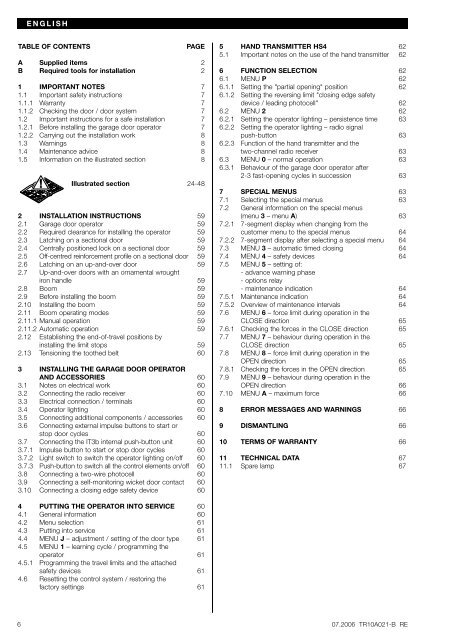
ENGLISH<br />
TABLE OF CONTENTS<br />
PAGE<br />
A Supplied items 2<br />
B Required tools for installation 2<br />
1 IMPORTANT NOTES 7<br />
1.1 Important safety instructions 7<br />
1.1.1 Warranty 7<br />
1.1.2 Checking the door / door system 7<br />
1.2 Important instructions for a safe installation 7<br />
1.2.1 Before installing the garage door operator 7<br />
1.2.2 Carrying out the installation work 8<br />
1.3 Warnings 8<br />
1.4 Maintenance advice 8<br />
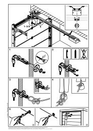
1.5 Information on the illustrated section 8<br />
Illustrated section 24-48<br />
2 INSTALLATION INSTRUCTIONS 59<br />
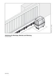
2.1 Garage door operator 59<br />
2.2 Required clearance for installing the operator 59<br />
2.3 Latching on a sectional door 59<br />
2.4 Centrally positioned lock on a sectional door 59<br />
2.5 Off-centred reinforcement profile on a sectional door 59<br />
2.6 Latching on an up-and-over door 59<br />
2.7 Up-and-over doors with an ornamental wrought<br />
iron handle 59<br />
2.8 Boom 59<br />
2.9 Before installing the boom 59<br />
2.10 Installing the boom 59<br />
2.11 Boom operating modes 59<br />
2.11.1 Manual operation 59<br />
2.11.2 Automatic operation 59<br />
2.12 Establishing the end-of-travel positions by<br />
installing the li<strong>mit</strong> stops 59<br />
2.13 Tensioning the toothed belt 60<br />
3 INSTALLING THE GARAGE DOOR OPERATOR<br />
AND ACCESSORIES 60<br />
3.1 Notes on electrical work 60<br />
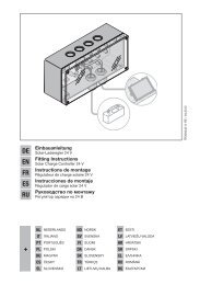
3.2 Connecting the radio receiver 60<br />
3.3 Electrical connection / terminals 60<br />
3.4 Operator lighting 60<br />
3.5 Connecting additional components / accessories 60<br />
3.6 Connecting external impulse buttons to start or<br />
stop door cycles 60<br />
3.7 Connecting the IT3b internal push-button unit 60<br />
3.7.1 Impulse button to start or stop door cycles 60<br />
3.7.2 Light switch to switch the operator lighting on/off 60<br />
3.7.3 Push-button to switch all the control elements on/off 60<br />
3.8 Connecting a two-wire photocell 60<br />
3.9 Connecting a self-monitoring wicket door contact 60<br />
3.10 Connecting a closing edge safety device 60<br />
5 HAND TRANSMITTER HS4 62<br />
5.1 Important notes on the use of the hand trans<strong>mit</strong>ter 62<br />
6 FUNCTION SELECTION 62<br />
6.1 MENU P 62<br />
6.1.1 Setting the "partial opening" position 62<br />
6.1.2 Setting the reversing li<strong>mit</strong> "closing edge safety<br />
device / leading photocell" 62<br />
6.2 MENU 2 62<br />
6.2.1 Setting the operator lighting – persistence time 63<br />
6.2.2 Setting the operator lighting – radio signal<br />
push-button 63<br />
6.2.3 Function of the hand trans<strong>mit</strong>ter and the<br />
two-channel radio receiver 63<br />
6.3 MENU 0 – normal operation 63<br />
6.3.1 Behaviour of the garage door operator after<br />
2-3 fast-opening cycles in succession 63<br />
7 SPECIAL MENUS 63<br />
7.1 Selecting the special menus 63<br />
7.2 General information on the special menus<br />
(menu 3 – menu A) 63<br />
7.2.1 7-segment display when changing from the<br />
customer menu to the special menus 64<br />
7.2.2 7-segment display after selecting a special menu 64<br />
7.3 MENU 3 – automatic timed closing 64<br />
7.4 MENU 4 – safety devices 64<br />
7.5 MENU 5 – setting of:<br />
- advance warning phase<br />
- options relay<br />
- maintenance indication 64<br />
7.5.1 Maintenance indication 64<br />
7.5.2 Overview of maintenance intervals 64<br />
7.6 MENU 6 – force li<strong>mit</strong> during operation in the<br />
CLOSE direction 65<br />
7.6.1 Checking the forces in the CLOSE direction 65<br />
7.7 MENU 7 – behaviour during operation in the<br />
CLOSE direction 65<br />
7.8 MENU 8 – force li<strong>mit</strong> during operation in the<br />
OPEN direction 65<br />
7.8.1 Checking the forces in the OPEN direction 65<br />
7.9 MENU 9 – behaviour during operation in the<br />
OPEN direction 66<br />
7.10 MENU A – maximum force 66<br />
8 ERROR MESSAGES AND WARNINGS 66<br />
9 DISMANTLING 66<br />
10 TERMS OF WARRANTY 66<br />
11 TECHNICAL DATA 67<br />
11.1 Spare lamp 67<br />
4 PUTTING THE OPERATOR INTO SERVICE 60<br />
4.1 General information 60<br />
4.2 Menu selection 61<br />
4.3 Putting into service 61<br />
4.4 MENU J – adjustment / setting of the door type 61<br />
4.5 MENU 1 – learning cycle / programming the<br />
operator 61<br />
4.5.1 Programming the travel li<strong>mit</strong>s and the attached<br />
safety devices 61<br />
4.6 Resetting the control system / restoring the<br />
factory settings 61<br />
6 07.2006 TR10A021-B RE