ProMatic - Hormann.fr
ProMatic - Hormann.fr
ProMatic - Hormann.fr
- No tags were found...

You also want an ePaper? Increase the reach of your titles
YUMPU automatically turns print PDFs into web optimized ePapers that Google loves.
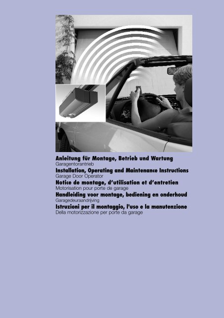
06.2004 TR10A014 REAnleitung für Montage, Betrieb und WartungGaragentorantriebInstallation, Operating and Maintenance InstructionsGarage Door OperatorNotice de montage, d’utilisation et d’entretienMotorisation pour porte de garageHandleiding voor montage, bediening en onderhoudGaragedeuraandrijvingIstruzioni per il montaggio, l'uso e la manutenzioneDella motorizzazione per porte da garage
Deutsch................................................................................. 3English .................................................................................. 6Français ................................................................................ 9Nederlands ......................................................................... 12Italiano ................................................................................ 15AA B C D EFB13 mm10 mm2Ø 5 mmØ 10 mm3 mm4 mm206.2004 TR10A014 RE
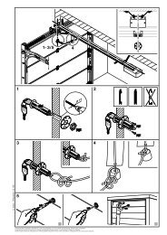
DEUTSCHSehr geehrter Kunde,wir bedanken uns, dass Sie sich für ein Qualitäts-Produkt ausunserem Hause entschieden haben. Bitte bewahren Sie dieseAnleitung sorgfältig auf!Beachten Sie bitte die nachfolgenden Hinweise, sie geben Ihnenwichtige Informationen für den Einbau und die Bedienung desGaragentorantriebes, damit Sie über viele Jahre Freude an diesemProdukt haben.1 Wichtige HinweiseACHTUNGEine falsche Montage bzw. eine falscheHandhabung des Antriebes kann zu ernsthaftenVerletzungen führen. Befolgen Siedaher bitte alle Anweisungen, die in dieserAnleitung enthalten sind!1.1 Wichtige SicherheitsanweisungenDer Garagentorantrieb ist ausschließlich für den automatischenBetrieb von federausgeglichenen SchwingundSectionaltoren im nichtgewerblichen Bereichvorgesehen.Der Einsatz im gewerblichen Bereich ist nichtzulässig!1.1.1 Wir sind von der Gewährleistung und der Produkthaftungbe<strong>fr</strong>eit, wenn ohne unsere vorherige Zustimmungeigene bauliche Veränderungen vorgenommen oderunsachgemäße Installationen gegen unsere vorgegebenenMontagerichtlinien ausgeführt bzw. veranlasst werden.Weiterhin übernehmen wir keine Verantwortung für denversehentlichen oder unachtsamen Betrieb des Antriebesund des Zubehörs sowie für die unsachgemäße Wartungdes Tores und dessen Gewichtsausgleich.Batterien und Glühlampen sind ebenfalls von den Gewährleistungsansprüchenausgenommen.1.1.2 Überprüfung des Tores / der ToranlageDie Konstruktion des Antriebes ist nicht für den Betriebschwerer Tore, das heißt Tore, die nicht mehr oder nurschwer von Hand geöffnet oder geschlossen werdenkönnen, ausgelegt. Aus diesem Grund ist es notwendig,vor der Antriebsmontage das Tor zu überprüfen undsicherzustellen, dass es auch von Hand leicht zubedienen ist.Hierzu heben Sie das Tor ca. einen Meter an und lassenes los. Das Tor sollte in dieser Stellung stehen bleibenund sich weder nach unten noch nach oben bewegen.Bewegt sich das Tor doch in eine der beiden Richtungen,so besteht die Gefahr, dass die Ausgleichsfedern nichtrichtig eingestellt oder defekt sind. In diesem Fall ist miteiner erhöhten Abnutzung und Fehlfunktionen der Toranlagezu rechnen.ACHTUNG: Lebensgefahr!Versuchen Sie nicht, die Ausgleichsfedern fürden Gewichtsausgleich des Tores oder derenHalterungen selbst auszuwechseln, nachzustellen,zu reparieren oder zu versetzen. Sie stehen untergroßer Spannung und können ernsthafteVerletzungen verursachen.Kontrollieren Sie außerdem die gesamte Toranlage(Gelenke, Lager des Tores, Seile, Federn undBefestigungsteile) auf Verschleiß und eventuelleBeschädigungen. Prüfen Sie, ob Rost, Korrosionoder Risse vorhanden sind. Die Toranlage ist nichtzu benutzen, wenn Reparatur- oder Einstellarbeitendurchgeführt werden müssen, denn ein Fehler inder Toranlage oder ein falsch ausgerichtetes Torkann ebenfalls zu schweren Verletzungen führen.HinweisBevor Sie den Antrieb installieren, lassen Sie zu Ihrereigenen Sicherheit Arbeiten an den Ausgleichsfedern desTores und falls erforderlich, Wartungs- und Reparaturarbeitennur durch einen qualifizierten Garagentor-Kundendienstausführen!1.2 Wichtige Anweisungen für eine sichere MontageDer Weiterverarbeiter hat darauf zu achten, dass dienationalen Vorschriften für den Betrieb von elektrischenGeräten eingehalten werden.1.2.1 Vor der Montage des Garagentorantriebes ist zu überprüfen,ob sich das Tor mechanisch in einem guten Zustandund im Gleichgewicht befindet. Weiterhin ist zuprüfen, ob sich das Tor richtig öffnen und schließen lässt(siehe Kapitel 1.1.2).Außerdem sind die mechanischen Verriegelungen desTores, die nicht für eine Betätigung mit einem Garagentorantriebbenötigt werden, außer Betrieb zu setzen. Hierzuzählen insbesondere die Verriegelungsmechanismendes Torschlosses (siehe Kapitel 2.2 bis 2.3).Der Garagentorantrieb ist für einen Betrieb in trockenenRäumen konstruiert und darf daher nicht im Freien montiertwerden. Die Garagendecke muss so ausgelegt sein,dass eine sichere Befestigung des Antriebes gewährleistetist. Bei zu hohen oder zu leichten Decken muss der Antrieban zusätzlichen Streben befestigt werden.1.2.2 Bei der Durchführung der Montagearbeiten sind diegeltenden Vorschriften zur Arbeitssicherheit zu befolgen.ACHTUNGBei Bohrarbeiten ist der Antrieb abzudecken,weil Bohrstaub und Späne zu Funktionsstörungenführen können.Der Freiraum zwischen dem höchsten Punkt des Toresund der Decke muss (auch beim Öffnen des Tores) mind.30 mm betragen (siehe Bild 1.1a/1.1b). Bei einem geringerenFreiraum kann, sofern genügend Platz vorhanden ist,406.2004 TR10A014 RE
DEUTSCHder Antrieb auch hinter dem geöffneten Tor montiert werden.In diesen Fällen muss ein verlängerter Tormitnehmereingesetzt werden, welcher separat zu bestellen ist. DerGaragentorantrieb kann max. 50 cm außermittig angeordnetwerden. Ausgenommen sind Sectionaltore mit einerHöherführung (H-Beschlag), hierbei ist jedoch einSpezialbeschlag erforderlich.Die notwendige Schutzkontaktsteckdose zum elektrischenAnschluss sollte ca. 50 cm neben dem Antriebskopfmontiert werden.Bitte überprüfen Sie diese Maße!HinweisDas Warnschild gegen Einklemmen ist an einer auffälligenStelle oder in der Nähe der festinstallierten Taster zumVerfahren des Antriebes dauerhaft anzubringen!1.5 Hinweise zum BildteilIm Bildteil wird die Antriebsmontage an einem Schwingtordargestellt.Bei Montageabweichungen am Sectionaltor, wirddieses zusätzlich gezeigt.Hierbei wird der Bildnummerierung der Buchstabea dem Schwingtor undO b dem Sectionaltor zugeordnet.Einige Bilder beinhalten zusätzlich das untenstehendeSymbol mit einem Textverweis. Unter diesen Textverweisenerhalten Sie wichtige Informationen zur Montage und zumBetrieb des Garagentorantriebes im anschließendenTextteil.Beispiel:2.21.3 Warnhinweise= siehe Textteil, Punkt 2.2Festinstallierte Steuerungsgeräte (wieTaster etc.), sind in der Sichtweite desTores zu montieren, aber entfernt vonsich bewegenden Teilen und in einerHöhe von mindestens 1,5 m.Sie sind unbedingt außer Reichweitevon Kindern anzubringen!Achten Sie darauf, dass- sich im Bewegungsbereich des Toreskeine Personen oder Gegenständebefinden dürfen.- Kinder nicht an der Toranlage spielen!- das Seil der mechanischen Entriegelungam Führungsschlitten nicht aneinem Dachträgersystem oder sonstigenVorsprüngen des Fahrzeugesoder des Tores hängen bleiben kann.ACHTUNGFür Garagen ohne einen zweiten Zugang ist eineNotentriegelung erforderlich, die ein möglichesAussperren verhindert.Diese ist separat zu bestellen und monatlich aufihre Funktionsfähigkeit zu überprüfen.ACHTUNGNicht mit dem Körpergewicht andie Entriegelungsglocke hängen!1.4 WartungshinweiseDer Garagentorantrieb ist wartungs<strong>fr</strong>ei. Zu Ihrer eigenenSicherheit empfehlen wir jedoch, die Toranlage einmalim Jahr durch einen qualifizierten Garagentor-Kundendienstüberprüfen zu lassen.06.2004 TR10A014 RE5
ENGLISHCONTENTSPAGEA Supplied Items 2B Required Tools for Installation 21 Important Notes 71.1 Important safety instructions 71.1.1 We shall be exempt <strong>fr</strong>om our warranty obligationsand product liability in the event that ... 71.1.2 Checking the door / door system 71.2 Important instructions for safe installation 71.2.1 Prior to installation 71.2.2 In carrying out the installation work 71.3 Warnings 81.4 Maintenance advice 81.5 Information on the illustrated section 8Illustrated Section 18-302 Installation Instructions 382.1 Required clearance for installing the operator 382.2 Door latches on an up-and-over door 382.3 Door latches on a sectional door 382.4 Up-and-over doors with a forged iron door handle 382.5 Central locking on a sectional door 382.6 Off-centred reinforcement profile on a sectional door 382.7 Tensioning the drive belt 383 Putting into Service / Connecting AdditionalComponents / Operation 383.1 Establishing the door's end-of-travel positionsby installing the limit stops 383.2 Notes on work involving electrics 383.3 Putting the operator into service 383.3.1 Deleting the door data 383.3.2 Programming the operator 393.3.3 Setting the maximum forces 393.4 Other adjustment options 403.5 Connecting of the additional components 403.5.1 Connecting the remote control 403.5.2 Connecting external IMPULSE buttons to start orstop travel cycles 413.5.3 Connecting an OFF-switch or a wicket doorcontact to halt and / or switch off the operator 413.5.4 Connecting a photocell or closing edge safetydevice 413.5.5 Connecting to the options relay 413.6 Notes on operating the garage door operator 413.6.1 Normal operation 423.6.2 Operation following actuation of the mechanicalrelease 423.6.3 Signals <strong>fr</strong>om the operator lighting 423.6.4 Error messages / diagnostic LED 424 Terms and Conditions of the Warranty 435 Technical Data 44Copyright.No part of this instruction manual may be reproducedwithout our permission.Subject to changes.6 06.2004 TR10A014 RE
ENGLISHDear Customer,Thank you for choosing a quality product <strong>fr</strong>om our company.Please keep these instructions safe for later reference!Please observe the following instructions, they provide you withimportant information on the safe installation and use of yourGarage Door Operator, thus ensuring that this product will giveyou trouble <strong>fr</strong>ee operation for many years to come.1 Important NotesATTENTIONIncorrect installation or handling of theoperator could result in serious injury.Please therefore follow these instructionsfully and with extreme care!1.1 Important safety instructionsThis garage door operator is designed exclusively forthe automated operation of spring-balanced up-and-overand sectional doors in the non-commercial sector.Use in the commercial sector is not permitted.1.1.1 We shall be exempt <strong>fr</strong>om our warranty obligationsand product liability in the event that the customercarries out his own structural changes or undertakesimproper installation work or arranges for same to becarried out without our prior approval and contrary tothe installation guidelines we have provided.Moreover, we shall accept no responsibility for the inadvertentor negligent operation of the operator andaccessories nor for the improper maintenance of thedoor and its counterbalance mechanism.Batteries and light bulbs are also not covered by thewarranty.1.1.2 Checking the door / door systemThe design of the operator is not suitable nor intendedfor the opening and closing of heavy doors, i.e. doorsthat can no longer easily be opened or closed manually.Before installing the operator, it is therefore necessaryto check the door and make sure that it canalso be easily moved by hand.To do this, raise the door approx. 1 metre and then let itgo. The door should retain this position, moving neitherup or down. If the door should move in any of the twodirections, there is a risk that the compensating springsare defective or incorrectly adjusted. In this case increasedwear and malfunctioning of the door system can be expected.06.2004 TR10A014 RECAUTION: Danger to life!Do not attempt to change, re- adjust, repair ormove the compensating springs for the door'scounterbalance mechanism or their holders. Thesprings are under great tension and can causeserious injury.In addition, check the entire door system (pivots,door bearings, cables, springs and fastenings)for wear and possible damage. Check for signsof rust, corrosion or <strong>fr</strong>actures. The door systemmay not be used if repair or adjustment workneeds to be carried out. Always remember thata fault in the door system or a misaligned doorcan also cause injury.NoteBefore installing the operator and in the interests of personalsafety, make sure that any work needed on thedoor's compensating springs is carried out by your garagedoor's service engineers. This also applies to anynecessary maintenance or repair work.1.2 Important instructions for safe installationAny further processing must ensure that the nationalregulations governing the operation of electrical equipmentare complied with.1.2.1 Before installing the garage door operator, checkthat the door is in a good mechanical condition and iscorrectly balanced. Further check whether the door opensand closes in the proper manner (see section 1.1.2).In addition, any of the door's mechanical locks and latchesnot needed for power operation of the garage doorshould be immobilised. This includes in particular anylocking mechanisms connected with the door lock (seesections 2.2 to 2.3).The garage door operator is designed for use in dry buildingsand therefore may not be installed outdoors. Thegarage ceiling must be constructed in such a way as toguarantee safe, secure anchoring of the operator. In thecase of ceilings that are too high or too lightweight, theoperator must be attached to additional braces.1.2.2 In carrying out the installation work the applicableregulations regarding working safety must be compliedwith.ATTENTIONAlways cover over the operator beforedrilling, since drilling dust and chippingscan lead to malfunctions.The clearance between the highest point of the door andthe ceiling (also when the door is opening) must be atleast 30 mm (see fig. 1.1a / 1.1b). If there is inadequateclearance, the operator may also be installed behind theopened door, provided sufficient space is available. Insuch instances an extended door link must be used. Thegarage door operator can be positioned off-centre bymax. 50 cm, the exception being sectional doors withhigh-lift tracks (track application "H"), where a specialtrack fitting is required.The required shockproof electric socket allowing the operatorto be connected to the electricity supply should beinstalled at a distance of approx. 50 cm <strong>fr</strong>om the operatorhead.Please check these dimensions!➤7
ENGLISHNoteSome of the figures also include the symbol shown belowA caution notice warning about the trap risk must betogether with a text reference. These references to specificpermanently fixed in a conspicuous place close to the permanentlyinstalled buttons used to actuate the operator.tant information regarding installation and operation of thetexts in the ensuing text section provide you with impor-garage door operator.1.3 WarningsExample:Permanently installed controls (such2.2as buttons or similar devices) shouldbe installed within sight of the door= see text section, point 2.2but well away <strong>fr</strong>om any moving partsand at a height of at least 1.5 metres.It is vital that they are installed outof the reach of children!Make sure that- neither persons nor objects are locatedwithin the door's range of travel.- children do not play around with thedoor system!- the cord of the mechanical releaseon the carriage cannot get caughtup in the ceiling's support systemor in any other protruding parts ofvehicles or the door.ATTENTIONFor garages without a second entrance, anemergency release must be fitted to ensurethat is no danger of getting locked out.This must be ordered separately and its functionchecked once a month.ATTENTIONDo not allow anyone to hang bodily<strong>fr</strong>om the pull cord with knob!1.4 Maintenance adviceThe garage door operator is maintenance-<strong>fr</strong>ee. For yourown safety, however, we recommend that you have thedoor system checked once a year by service engineersqualified to inspect and service garage doors.1.5 Information on the illustrated sectionThe illustrated section shows installation of the operatoron an up-and-over door.Where installation differs for a sectional door, this isshown in addition.In this instance, letters are assigned to the figuresas follows:a is assigned to the up-and-over door andO b to the sectional door.8 06.2004 TR10A014 RE
FRANÇAISTABLE DES MATIERESPAGE4 Conditions de garantie 51A Articles livrés 2B Outillage nécessaire au montage 25 Caractéristiques techniques 511 Remarques importantes 101.1 Consignes importantes de sécurité 101.1.1 Le fabricant n'acceptera... 101.1.2 Contrôle de la porte / de l’installation de porte 101.2 Consignes importantes de sécurité pour le montage 101.2.1 Avant d’installer la motorisation 101.2.2 Lors des travaux de montage 101.3 Avertissement 111.4 Consignes d’entretien 111.5 Description fonctionnelle 11Partie illustrée 18-302 Instructions de montage 452.1 Espace libre nécessaire au montage de lamotorisation 452.2 Verrous mécaniques dans le cas de portesbasculantes 452.3 Verrous mécaniques dans le cas de portessectionnelles 452.4 Portes basculantes avec poignées enferronnerie d’art 452.5 Portes sectionnelles avec fermeture centrale 452.6 Portes sectionnelles avec profilé de renforcementexcentré 452.7 Tension de la courroie 453 Mise en service / Raccordement des composantssupplémentaires / Exploitation 453.1 Détermination des positions finales de la portepar fixation des butées 453.2 Instructions relatives aux travaux électriques 453.3 Mise en service de la motorisation 453.3.1 Effacement des données 463.3.2 Paramétrage de la motorisation 463.3.3 Réglage des forces maximales 463.4 Autres possibilités de réglage 473.5 Raccordement des composants supplémentaires 473.5.1 Raccordement du récepteur de télécommande 483.5.2 Raccordement d'un bouton-poussoir externe àimpulsions 483.5.3 Raccordement d’un interrupteur ou d’un contactde portillon 483.5.4 Raccordement d'une sécurité de contact 483.5.5 Raccordement d'un relais optionnel 483.6 Instructions relatives à l'exploitation de lamotorisation pour porte de garage 493.6.1 Fonctionnement normal 493.6.2 Fonctionnement après manœuvre manuelledu déverrouillage mécanique 493.6.3 Message de la lampe de la motorisation 493.6.4 Message d'erreur/diode de diagnostic 5006.2004 TR10A014 REDroits d'auteur réservés.Reproduction même partielle uniquement avec notre autorisation.Changements de construction réservés.9
FRANÇAISCher client,Nous vous félicitons d'avoir porté votre choix sur l'un des produitsde haute qualité de notre société. Veuillez conserver soigneusementla présente notice.Respectez les consignes ci-après, qui vous fournissent desinformations importantes pour le montage et la commande devotre motorisation pour porte de garage. Vous pourrez ainsiprofiter de ce produit pendant de nombreuses années.Contrôlez en outre toute l'installation de la porte- articulations, roulements de porte, câbles, ressortset points de fixation - pour voir s'il n'y a pasd'usure ou de dommages éventuels. Vérifiez s'iln'y a pas de rouille, de corrosion ou de fissures.N’utilisez pas l'installation de porte si des travauxde réparation ou de réglage doivent être exécutés.En effet, une panne dans l'installation de porte ouun mauvais réglage peut provoquer des blessuresgraves.1. Remarques importantesATTENTIONLe montage ou l'utilisation incorrects de lamotorisation peut provoquer des blessuressérieuses. Veuillez donc respecter scrupuleusementtoutes les instructions contenuesdans la présente notice.1.1 Consignes importantes de sécuritéLa motorisation de porte de garage est destinée exclusivementà l'ouverture et à la fermeture automatiques deportes de garage basculantes et sectionnelles équilibréespar ressort dans le cadre d'un usage résidentiel.L'utilisation dans le domaine professionnel estinterdite.1.1.1 Le fabricant n'acceptera aucune responsabilité etn'appliquera aucune garantie si des modificationsstructurelles sont apportées au système ou si celui-cin'est pas installé conformément aux instructions demontage, sauf autorisation préalable. En outre, nousn'accepterons aucune responsabilité en cas d'utilisationnégligente ou inconsidérée de la motorisation, ni en casde mauvais entretien de la porte, de ses accessoires oude son système d'équilibrage.Les piles et les ampoules ne sont pas couvertes par lagarantie.1.1.2. Contrôle de la porte / de l’installation de porteCette motorisation n'est pas destinée au levage desportes lourdes, c’est-à-dire des portes qui ne peuventplus être ouvertes et fermées manuellement, ou seulementau prix d'un effort important. En conséquence, ilest impératif de vérifier avant le montage si la portepeut être aisément manœuvrée à la main.Pour ce faire, levez la porte d'environ 1 mètre et relâchez-la.La porte doit rester dans cette position et ne se déplacerni vers le haut, ni vers le bas. Si la porte se déplace dansl'un de ces deux sens, il est possible que les ressortsd'équilibrage ne soient pas bien réglés ou soient défectueux.Dans ce cas, l'installation de porte s'usera plusrapidement et présentera des problèmes de fonctionnement.ATTENTION : danger de mort!N'essayez jamais de remplacer, de rajuster, deréparer ou de déplacer les ressorts du systèmed'équilibrage de la porte ou ses fixations. Ils sontsous tension importante et peuvent provoquerdes blessures graves.RemarqueAvant d'installer la motorisation, faites effectuer, pour votrepropre sécurité, les travaux d’équilibrage et si nécessaire lestravaux d'entretien et de réparation par le service clientèledu fabricant de votre porte de garage!1.2 Consignes importantes de sécurité pour le montageLe monteur devra veiller à respecter les prescriptionsnationales relatives à l'installation d'appareils électriques.1.2.1 Avant d'installer la motorisation, vérifiez que la porteest en bon état mécanique, qu'elle se trouve en équilibreet qu'elle s'ouvre et se ferme correctement (voir 1.1.2).De plus, tous les verrous mécaniques inutiles au fonctionnementd'une motorisation doivent être mis hors serviceet en particulier le système de verrouillage de la serrurede la porte (voir points 2.2 et 2.3).La motorisation est conçue pour être installée dans unendroit sec et ne peut donc pas être montée à l'extérieur.Le plafond du garage doit être réalisé en un matériau quigarantit une fixation sûre de la motorisation. Si le plafondest trop haut ou insuffisamment résistant, la motorisationdoit être montée sur des montants supplémentaires.1.2.2 Lors des travaux de montage, les consignes desécurité en vigueur pour la sécurité sur les lieux detravail doivent être respectées.ATTENTIONCouvrez la motorisation si vous effectuezdes travaux de forage. La poussière et lescopeaux produits lors du forage peuventnuire à son bon fonctionnement.L'espace libre entre le point le plus élevé de la porte et leplafond doit atteindre au minimum 30 mm (même lors dubasculement de la porte) (voir figure 1.1a/1.1b). Si l'espacelibre est plus réduit, il est possible d'installer la motorisationderrière la porte ouverte, pour autant qu'il y ait assezde place. Dans ce cas, utilisez un entraîneur de porte pluslong. La motorisation de porte peut être excentrée de 500mm au maximum, sauf en ce qui concerne les portessectionnelles avec rails de guidage rehaussés (ferrure H),pour lesquelles des ferrures spéciales sont nécessaires.La prise de contact de sécurité indispensable doit êtremontée à 50 cm environ à côté de la tête d'entraînement.Veuillez s.v.p. contrôler ces distances!10 06.2004 TR10A014 RE
FRANÇAISRemarqueDes panneaux d'avertissement (risque de pincement)doivent être placés à demeure à un endroit bien visible ouà proximité des boutons-poussoirs fixes de la commande.illustrations contiennent de plus le symbolecidessous et une référence à un paragraphe. Vous trouverezdans le paragraphe correspondant à cette référencedes informations importantes concernant le montage etle maniement de la motorisation de la porte de garage.1.3 AvertissementLes appareils de commande fixes(par exemple boutons-poussoirs)doivent être placés en vue de la porte,mais à distance des pièces mobiles età une hauteur minimale de 1,5 m.Ils doivent absolument être installéshors de portée des enfants!Exemple :2.2= voir partie texte, paragraphe 2.2Veillez à ce que- aucun objet ou personne ne setrouve sur le trajet d'une porteen mouvement.- aucun enfant ne joue à proximitéde l’installation de la porte- le câble de déverrouillage mécaniquene puisse pas se coincer dans unegalerie de toit ou d'autres partiesfaisant saillie sur le véhicule ou surla porte.ATTENTIONPour les garages qui ne disposent pas d'unedeuxième sortie, le placement d'un dispositif dedéverrouillage de secours est indispensable. Ilest destiné à empêcher qu’une personne ne seretrouve enfermée dans le garage. Ce dispositifdoit être commandé séparément et son bonfonctionnement doit être vérifié chaque mois.ATTENTIONNe vous suspendez jamais de tout votrepoids à la corde de déverrouillage!1.4 Consignes d’entretienLa motorisation ne demande pas d'entretien. Cependant,pour votre propre sécurité, nous vous recommandons defaire vérifier une fois par an l'ensemble de l'installationpar un professionnel.Certaines1.5 Présentation de la section illustréeVous trouverez dans la section illustrée les détails demontage de la motorisation pour une porte basculante.Si elle présente des différences de montage, la portesectionnelle sera illustrée également.La lettre a concerne la porte basculante, etLa lettre Ob la porte sectionnelle.06.2004 TR10A014 RE11
NEDERLANDSINHOUDSOPGAVEBLZ.A Meegeleverde artikelen 2B Benodigde werktuigen voor de montage 21 Belangrijke aanwijzingen 131.1 Belangrijke veiligheidsaanwijzingen 131.1.1 Garantiebepalingen en productaansprakelijkheid 131.1.2 Controle van de deur/deurinstallatie 131.2 Belangrijke aanwijzingen voor een veilige montage 131.2.1 Voor de montage 131.2.2 Bij montagewerkzaamheden 131.3 Waarschuwingsaanwijzingen 141.4 Onderhoudsaanwijzingen 141.5 Aanwijzingen bij de illustraties 14Illustraties 18-302 Montagehandleiding 522.1 Benodigde vrije ruimte voor de montage vande aandrijving 522.2 Vergrendelingen bij de kanteldeur 522.3 Vergrendelingen bij de sectionaldeur 522.4 Kanteldeuren met kunstsmeedijzeren handgreep 522.5 Middenvergrendeling bij de sectionaldeur 522.6 Excentrisch versterkingsprofiel bij de sectionaldeur 522.7 Spanning van de aandrijvingsriem 523 Inbedrijfstelling / Aansluiting van deextra componenten / Bediening 523.1 Vastleggen van de eindposities door montagevan de eindaanslagen 523.2 Richtlijnen voor elektronische werkzaamheden 523.3 Inbedrijfstelling van de aandrijving 523.3.1 Wissen van de deurgegevens 533.3.2 Aanleren van de aandrijving 533.3.3 Instellen van de maximale krachten 533.4 Andere instelmogelijkheden 543.5 Aansluiting van extra componenten 543.5.1 Aansluiting van de ontvanger 553.5.2 Aansluiting van een externe "impuls”-toets 553.5.3 Aansluiting van een uitschakelaar of eenloopdeurcontact 553.5.4 Aansluiting van een fotocel of eenonderloopbeveiliging 553.5.5 Aansluiting aan een optioneel relais 553.6 Aanwijzingen voor de bediening van degaragedeuraandrijving 553.6.1 Normale bediening 563.6.2 Werking na het bedienen van de mechanischeontgrendeling 563.6.3 Meldingen van de aandrijvingsverlichting 563.6.4 Foutmeldingen/diagnose-LED 564 Garantiebepalingen 575 Technische gegevens 58Door de auteurswet beschermd.Gehele of gedeeltelijke nadruk is zonder onze toestemmingniet toegestaan. Constructiewijzigingen voorbehouden.12 06.2004 TR10A014 RE
NEDERLANDSGeachte klant,Wij danken U dat U heeft gekozen voor een kwaliteitsproductuit ons huis. Bewaar deze handleiding zorgvuldig!Let op de hiernavolgende aanwijzingen. Zij geven U belangrijkeinformatie over de montage en de bediening van de garagedeuraandrijvingzodat U jarenlang veel plezier zult beleven aandit product.1 Belangrijke aanwijzingenATTENTIEEen foutieve montage of gebruik van deaandrijving kan leiden tot ernstige letsels.Neem alle in deze handleiding opgenomenaanwijzingen in acht!1.1 Belangrijke veiligheidsaanwijzingenDe garagedeuraandrijving is uitsluitend bestemd voorde automatische bediening van kantel- en sectionaldeuren,uitgebalanceerd door veren, voor niet-industriële toepassing.Toepassing in de bedrijfssector is niet toegestaan!1.1.1 Wij zijn vrijgesteld van garantie of productaansprakelijkheidindien, zonder onze voorafgaande toestemming,wijzigingen of ondeskundige installaties integenstrijd met onze montagerichtlijnen worden aangebracht.Wij zijn ook niet verantwoordelijk voor verkeerdof achteloos gebruik van de aandrijving en van de toebehorenof het ondeskundig onderhoud van de deur envan de gewichtsuitbalancering.De garantiebepalingen zijn niet van toepassing op batterijenen gloeilampen.1.1.2 Controle van de deur/deurinstallatieDe aandrijving werd niet ontworpen voor de bedieningvan zware deuren, d.w.z. deuren die niet meer of slechtszeer moeilijk met de hand kunnen worden geopend ofgesloten. Om die reden is het noodzakelijk de deurte controleren voor de montage van de aandrijvingen te verzekeren dat de deur ook handmatig gemakkelijkte bedienen is.Hef de deur ca. 1 meter omhoog en laat ze los. De deurmoet in deze positie blijven staan en noch naar onder,noch naar boven bewegen. Beweegt de deur toch in éénvan beide richtingen, dan bestaat het gevaar dat de uitbalanceringniet juist ingesteld of defect is. In dit gevalmoet met slijtage of slechte functie van de deur rekeningworden gehouden.06.2004 TR10A014 REOpgelet: levensgevaar!Probeer niet zelf de veren voor de uitbalanceringvan de deur of de veerhouders te vervangen, bijte regelen, te herstellen of te verplaatsen. Zijstaan onder grote spanning en kunnen ernstigeletsels veroorzaken.Controleer bovendien de volledige deur (hefarmen,lagers, kabels, veren en bevestigingspunten) opslijtage en eventuele beschadigingen. Ga na o<strong>fr</strong>oest, corrosie of scheuren aanwezig zijn. Dedeur niet gebruiken wanneer herstellingen o<strong>fr</strong>egelingen moeten gebeuren omdat fouten inde deurinstallatie of een slecht geregelde deureveneens letsels kunnen veroorzaken.TipAlvorens de aandrijving te installeren laat U, voor uw eigenveiligheid, werkzaamheden aan de compensatieveren vande deur en, indien noodzakelijk, onderhouds- en herstellingswerkenalleen door een gekwalificeerde garagedeurservicedienstuitvoeren!1.2 Belangrijke aanwijzingen voor een veilige montageDe gebruiker dient erop te letten dat de nationale voorschriftenvoor het gebruik van elektrische apparaten inacht worden genomen.1.2.1 Voor de montage van de garagedeuraandrijving moetworden nagegaan of de deur mechanisch in goede toestanden in evenwicht is. Ook moet gecontroleerd wordenof de deur goed geopend en gesloten kan worden (ziehoofdstuk 1.1.2).Bovendien moeten de mechanische vergrendelingen, dieniet noodzakelijk zijn voor de elektrische bediening vande deur, buiten werking worden gesteld. Dit geldt in hetbijzonder voor het vergrendelingsmechanisme van hetdeurslot (zie hoofdstuk 2.2 en 2.3).De aandrijving is ontworpen voor gebruik in droge ruimtenen mag dus niet in de openlucht worden gemonteerd.Het plafond van de garage moet stevig genoeg zijn omeen veilige bevestiging van de aandrijving te verzekeren.Bij een te hoog of te licht plafond moet de aandrijvingaan extra versterkingsprofielen worden bevestigd.1.2.2 Bij montagewerkzaamheden moeten de veiligheidsvoorschriftenin acht worden genomen.Let opBij boorwerkzaamheden moet de aandrijvingafgedekt worden omdat boorstof en spaanderskunnen leiden tot functiestoringen.De vrije ruimte tussen het hoogste punt van de deur enhet plafond (ook bij het openen van de deur) moet min.30 mm bedragen (zie afbeelding 1.1a / 1.1b). Bij geringevrije ruimte kan de aandrijving, voor zover voldoende plaatsaanwezig is, ook achter de geopende deur gemonteerdworden. In dit geval moet een verlengde deurmeenemergebruikt worden, die afzonderlijk moet besteld worden.De deuraandrijving kan max. 50 cm buiten het middengeplaatst worden. Uitzondering hierop zijn sectionaldeurenmet verhoogd looprailbeslag (H-beslag). Hier is een speciaalbeslag nodig.Het noodzakelijke veiligheidsstopcontact voor de elektrischeaansluiting moet ca. 50 cm naast de motor wordengeplaatst.Deze maat moet gecontroleerd worden! ➤13
NEDERLANDSAanwijzingEnkele illustraties bevatten aanvullend onderstaand symboolmet een tekstverwijzing. Onder deze tekstverwijzingenHet waarschuwingsbordje tegen het knellen moet permanentop een opvallende plaats of in de nabijheid van een vaststaat belangrijke informatie over de montage en de bedieningvan de garagedeuraandrijving in het overeenkom-bedieningselement van de aandrijving aangebracht worden!stig tekstgedeelte.1.3 WaarschuwingsaanwijzingenVoorbeeld:Vaste bedieningselementen (zoals2.2drukknoppen) moeten in het zicht vande deur worden gemonteerd, maar= zie tekstdeel, punt 2.2weg van de bewegende delen en opeen hoogte van minstens 1,5 meter.Zij moeten absoluut buiten het bereikvan kinderen worden aangebracht!U dient erop te letten dat- zich geen personen of voorwerpenin het bewegingsbereik van de deurbevinden.- kinderen niet vlakbij de deur spelen!- het trekkoord van de mechanischeontgrendeling aan de geleidingssledeniet kan blijven hangen aan eendakligger of aan uitspringende delenvan de wagen of de deur.LET OP:Voor garages zonder tweede toegang is eennoodontgrendeling vereist, die het mogelijkbuitensluiten verhindert. Deze moet afzonderlijkworden besteld en maandelijks op een goedewerking worden gecontroleerd.OPGELETniet met uw volle lichaamsgewichtaan de ontgrendelingsklok trekken!1.4 OnderhoudsaanwijzingenDe garagedeuraandrijving is onderhoudsvrij. Voor uweigen veiligheid bevelen wij echter aan de deur eenmaalper jaar te laten controleren door een gekwalificeerdegaragedeur-servicedienst.1.5 Aanwijzingen bij de illustratiesIn de illustraties wordt de montage van de aandrijvingaan een kanteldeur voorgesteld.Bij montage-afwijkingen aan een sectionaldeur wordt ditaanvullend getoond.Hierbij wordt bij de beeldnummering de lettera voor kanteldeuren enO b voor sectionaldeuren toegevoegd14 06.2004 TR10A014 RE
ITALIANOSOMMARIOPAGINA4 Garanzia 65A Articoli in dotazione 2B Attrezzi necessari per il montaggio 25 Dati tecnici 651 Importanti avvertenze 161.1 Importanti avvertenze per la Sua sicurezza 161.1.1 Noi siamo sollevati dalla garanzia e dalla responsabilitàper il prodotto qualora… 161.1.2 Controllo della porta 161.2 Avvertenze importanti per un montaggio sicuro 161.2.1 Prima del montaggio 161.2.2 Durante i lavori di montaggio 161.3 Avvertimenti 171.4 Avvertenze per la manutenzione 171.5 Indicazioni per la parte illustrata 17Parte illustrata 18-302 Istruzioni per il montaggio 592.1 Spazio libero necessario per il montaggio dell'unitàdi motorizzazione 592.2 Dispositivi di bloccaggio meccanico della portabasculante 592.3 Dispositivi di bloccaggio meccanico della portasezionale 592.4 Porte basculanti con maniglia in ferro battuto 592.5 Porta sezionale con serratura disposta al centro 592.6 Porta sezionale con profilo di rinforzo applicatofuori asse 592.7 Tensionamento della cinghia di trasmissione 593 Messa in funzione / Collegamento deicomponenti aggiuntivi / Funzionamento 593.1 Stabilire le posizioni di fine corsa tramite ilmontaggio degli arresti di fine corsa 593.2 Avvertenze per gli interventi sull'impianto elettrico 593.3 Messa in funzione della motorizzazione 593.3.1 Cancellazione dei dati della porta 603.3.2 Operazione di apprendimento per la motorizzazione 603.3.3 Regolazione degli sforzi massimi 603.4 Altre possibilità di regolazione 613.5 Collegamento dei componenti supplementari 623.5.1 Collegamento del radioricevitore 623.5.2 Collegamento dei pulsanti esterni ad impulso 623.5.3 Collegamento di un interruttore o di un contattoporta pedonale 623.5.4 Collegamento di una fotocellula o di una costoladi sicurezza 623.5.5 Collegamento a un relè opzionale 633.6 Avvertenze per il funzionamento dellamotorizzazione 633.6.1 Funzionamento normale 633.6.2 Funzionamento dopo l'azionamento dellosbloccaggio meccanico 633.6.3 Segnalazioni dell'illuminazione motorizzazione 643.6.4 Messaggi d'errore / LED di diagnostica 64Diritti d'autore riservati.Riproduzione, anche solo parziale, previa nostra approvazione.La Ditta si riserva di apportare modifiche al prodotto.06.2004 TR10A014 RE15
ITALIANOGentile cliente,siamo lieti che Lei abbia scelto un prodotto di nostra produzione.La preghiamo di conservare queste istruzioni con cura e di leggereattentamente le seguenti avvertenze, che Le fornirannoimportanti informazioni sull'installazione e sull'uso della motorizzazione.Siamo certi che questo prodotto Le procurerà grandesoddisfazione per molti anni.1 Importanti avvertenzeATTENZIONE!Un montaggio o un uso sbagliato dellamotorizzazione può comportare gravi lesionifisiche. Pertanto La preghiamo di seguiretutte le avvertenze contenute nelle presentiistruzioni!1.1 Importanti avvertenze per la Sua sicurezzaQuesta motorizzazione è stata ideata esclusivamenteper la manovra automatica di porte basculanti e sezionalia molle compensatrici ad utilizzo residenziale.L'impiego industriale non è consentito!1.1.1 Noi siamo sollevati dalla garanzia e dalla responsabilitàper il prodotto qualora il cliente effettui modifichecostruttive senza previo consenso da parte nostra oppureesegua/faccia eseguire lavori d'installazione inadeguati onon conformi alle nostre istruzioni di montaggio.Inoltre decliniamo ogni responsabilità in caso di un usonon corretto o di manutenzione inadeguata della porta,degli accessori e del contrappeso della porta.Le batterie e le lampadine sono escluse dalla garanzia.1.1.2 Controllo della portaQuesto tipo di costruzione della motorizzazione non èadatto all'impiego per porte pesanti, vale a dire per porteche non possono essere manovrate manualmente, osolo con molta difficoltà. Per questi motivi, prima delmontaggio della motorizzazione, è indispensabilecontrollare la porta ed assicurarsi che la manovramanuale sia di facile esecuzione.A tale scopo sollevare la porta di 1 metro circa, quindilasciarla ricadere. La porta dovrebbe arrestarsi in questaposizione, senza spostarsi né verso l'alto né verso il basso.Se invece la porta si muove in una delle due direzioni, èprobabile che le molle compensatrici non siano adeguatamenteregolate o che siano difettose. In questo casoc'è da aspettarsi un maggiore consumo o un'anomalianel funzionamento della porta.ATTENZIONE! Pericolo di morte!È assolutamente vietato sostituire, regolare, riparareo spostare le molle compensatrici per il contrappesoo i relativi supporti: la tensione delle mollepuò provocare gravi lesioni.Controllare inoltre che sull'intera porta (snodi,supporti, funi, molle, elementi di fissaggi) nonsiano presenti punti d’usura ed eventuali difetti.Verificare anche che non ci siano tracce di ruggine,corrosione o segni d’incrinature. Nel caso in cuifossero necessari interventi di riparazione o diregolazione, la porta non dovrà essere manovrata,perché un suo difetto o una porta allineata inmodo sbagliato possono anch'essi essere causadi gravi lesioni!AvvertenzaPrima di installare la motorizzazione, far eseguire, per motividi sicurezza, i lavori sulle molle compensatrici della porta e,se necessario, i lavori di riparazione o di manutenzioneesclusivamente dal Servizio clienti del rivenditore!1.2 Avvertenze importanti per un montaggio sicuroL'elettricista deve prestare attenzione che vengano rispettatele norme locali per l'uso degli apparecchi elettrici.1.2.1 Prima del montaggio della motorizzazione controllareche la porta sia in buono stato, sia equilibrata e che siapra e chiuda perfettamente. Controllare inoltre se la portasi apre e di chiude correttamente (vedi capitolo 1.1.2).Inoltre dovranno essere messi fuori funzione tutti i dispositividi bloccaggio meccanico della porta che non vengonoutilizzati nella manovra motorizzata. Particolareattenzione va dedicata ai meccanismi di bloccaggiodella serratura (vedi capitoli 2.2-2.3).La motorizzazione può essere utilizzata solo in localiasciutti, quindi non deve essere montata all'aperto. Ilsoffitto del garage deve essere realizzato in modo dagarantire un fissaggio sicuro della motorizzazione. Incaso di soffitti troppo alti o troppo leggeri, la motorizzazionedovrà essere fissata ulteriormente con traverse.1.2.2 Durante i lavori di montaggio osservare le normevigenti per la sicurezza sul lavoro.ATTENZIONE!Durante i lavori di trapanatura coprire lamotorizzazione dato che i trucioli di trapanaturapotrebbero causare anomalie nelfunzionamento.Lo spazio libero tra il punto massimo della porte ed ilsoffitto (anche durante l'apertura della porta) deve esserealmeno di 30 mm (vedi figura 1.1a / 1.1b). In caso di spazioinsufficiente è anche possibile fissare la motorizzazioneal soffitto nelle vicinanze del bordo superiore della porta,quando questa è completamente aperta (ammesso cisia spazio sufficiente). In questi casi deve essere utilizzatoun braccio di trascinamento porta prolungato da ordinareseparatamente. La motorizzazione può essere posta fuoriasse di max. 50 cm. Fanno eccezione le porte sezionalicon guide prolungate in altezza (applicazione H) per lequali è necessario l'accessorio speciale.La presa tipo Schuko necessaria per il collegamentoelettrico deve essere posizionata a 50 cm circa, accantoalla testa motore.Controllare le misure suddette!16 06.2004 TR10A014 RE
ITALIANOAvvertenzaAlcune illustrazioni sono inoltre dotate del simbolo sottostante,insieme con un rimando alla parte delle istru-Il cartello che segnala il pericolo di schiacciamento deveessere fissato in un punto ben visibile o nelle vicinanze deizioni. Questo rimando Le fornirà importanti informazioni,pulsanti per la manovra della motorizzazione.relative al montaggio e all'uso della motorizzazione contenutenella parte delle istruzioni.1.3 AvvertimentiEsempio:Gli elementi di comando ad installazionefissa (ad es. pulsanti ecc.)2.2dovranno essere installati in modo= vedi parte istruzioni, punto 2.2da essere ben visibili dalla porta,ma lontani da elementi mobili e adun'altezza di almeno 1,5 m.Installare questi elementi lontano dallaportata dei bambini!Accertare che- nella zona di manovra della portanon si trovino né persone né oggetti;- non vi siano bambini che giocanocon la porta;- che la corda per lo sblocco meccanicodella motorizzazione non possaimpigliarsi ad una trave del tetto o asporgenze del veicolo o della porta.ATTENZIONE!Per garage senza secondo accesso è necessariouno sblocco d'emergenza che escluda la possibilitàdi rimanere chiusi dentro.Questo sblocco d'emergenza deve essere ordinatoseparatamente e il suo funzionamento deveessere controllato ogni mese.ATTENZIONELa fune dello sblocco d'emergenza nondovrà essere tirata con una forza eccessiva!1.4 Avvertenze per la manutenzioneLa motorizzazione non richiede nessuna manutenzione.Per la Sua sicurezza Le consigliamo, però, di far controllareuna volta all'anno porta e motorizzazione dalServizio clienti del rivenditore.1.5 Indicazioni per la parte illustrataNella parte illustrata è raffigurato il montaggio dell'unitàdi motorizzazione su una porta basculante.In caso di variazioni nel montaggio su una porta sezionale,verrà raffigurato anche questo tipo di porta.Accanto al numero delle illustrazioni si trova la letteraa che indica il montaggio su una porta basculante eO b su una porta sezionale.06.2004 TR10A014 RE17
1a2.21.2a1.3a1.1a1.2.21.2a1.3a1.2a 301.3a1806.2004 TR10A014 RE
1b2.31.4b1.5b1.6b1.4b1.5b1.6b1.2b1.3b1.2b1.1b1.2b1.2.2 2.3 301.3b06.2004 TR10A014 RE 19
1.4b151.5b1.6b2a2.4BØ 51 / 21 / 22006.2004 TR10A014 RE
3.1aN 801/2 1/21/21/2B3.2aN 802.41/2 1/21/21/2B3.3aDF 981/2 1/21/21/2Ø 1090A3.4aF 801/21/260Ø 1067A06.2004 TR10A014 RE 21
2b2.5BØ 53.1bLTE/LPU/LTH 40Ø 10≥113A3.2bLTE/LPU/LTH 40Ø 106055A> 552206.2004 TR10A014 RE
44.2/4.34.14.2/4.34.14.2 4.33.106.2004 TR10A014 RE 23
55.15.55.2-5.45.1 5.2 5.3DC5.4 5.5Ø 10300 max.60A2406.2004 TR10A014 RE
6a6.1a-6.2a6.1aN 80EE6.2aDF 98EE06.2004 TR10A014 RE 25
6b6.1b-6.2b6.1bEE6.2bEE2606.2004 TR10A014 RE
73.183.19F06.2004 TR10A014 RE 27
103.3.2-3) / 3.410.110.29-1010.2 / 11-16113.5.120 21a 5 1213 74 20.6 .5 .8BNWHGN123.5.220 21a 5 1213 74 20.6 .5 .82806.2004 TR10A014 RE
133.5.320 21a 5 1213 74 20.6 .5 .80V143.5.4+24VA20 21a 5 1213 74 20.6 .5 .88,2 k0V153.5.4+24VB20 21a 5 1213 74 20.6 .5 .88,2 k0V163.5.520 21a 5 1213 74 20.6 .5 .8NL1173.3.22X2MX1M Trafo1/N~230/240 V50/60HzSP1 P224V/10WB(A)15sA B CA B COFFONLED20 21a 5 1213 74 205 21b 20.6 .5 .806.2004 TR10A014 RE 29
183.3.1193.3.2 / 11 x203.3.221.13.3.3-4)21.230 06.2004 TR10A014 RE
DEUTSCH2 Montageanleitung2.1 Benötigter Freiraum für die Montage des AntriebesBei der Antriebs-Montage muss der Freiraum zwischendem höchsten Punkt beim Torlauf und der Decke mind.30 mm betragen (siehe Bild 1.1a / 1.1b).2.2 Die mechanischen Tor-Verriegelungen am Schwingtorsind außer Betrieb zu setzen (siehe Bild 1a). Bei den hiernicht aufgeführten Tormodellen sind die Schnäpperbauseits festzustellen.2.3 Am Sectionaltor ist die mechanische Torinnenverriegelungkomplett zu demontieren (siehe Bild 1b).06.2004 TR10A014 REACHTUNGBei der Antriebs-Montage muss dasHandseil entfernt werden(siehe Bild 1.2b)2.4 HinweisSchwingtore mit einem kunstschmiedeeisernenTorgriff Abweichend vom Bildteil (siehe Bild 2a / 3.2a)sind bei diesen Toren die Sturzgelenkbefestigung undder Mitnehmerwinkel außermittig anzubringen.2.5 Mittiger Torverschluss am SectionaltorBei Sectionaltoren mit einem mittigen Torverschluss istdie Sturzgelenkbefestigung und der Mitnehmerwinkelaußermittig anzubringen (siehe Bild 2b).2.6 Außermittiges Verstärkungsprofil am SectionaltorBeim außermittigen Verstärkungsprofil am Sectionaltorist der Mitnehmerwinkel am nächstgelegenen Verstärkungsprofilrechts oder links zu montieren (siehe Bild 2b).HinweisAbweichend vom Bildteil, sind bei Holztoren die Holzschrauben5 x 35 aus dem Beipack des Tores zu verwenden(Bohrung Ø 3 mm).2.7 Spannung des AntriebgurtesDer Zahngurt der Antriebsschiene besitzt eine werkseitigeoptimale Vorspannung. In der Anfahr- und Abbremsphasekann es bei großen Toren zu einem kurzzeitigen Heraushängendes Gurtes aus dem Schienenprofil kommen.Dieser Effekt bringt jedoch keine technischen Einbußenmit sich und wirkt sich auch nicht nachteilig auf die Funktionund Lebensdauer des Antriebes aus.ACHTUNGGreifen Sie nicht während einer Torfahrtmit den Fingern in die Führungsschiene ➜Quetschgefahr!3 Inbetriebnahme / Anschluss vonZusatzkomponenten / Betrieb3.1 Festlegen der Tor-Endlagen durch die Montageder Endanschläge1) Der Endanschlag für die Endlage "Tor-Auf" ist zwischendem Führungsschlitten und dem Antrieb lose in dieFührungsschiene einzusetzen (siehe Bild 4) und dasTor ist, nach der Montage des Tormitnehmers (sieheBild 6.1a / 6.2a / 6.1b / 6.2b), per Hand in die Endlage"Tor-Auf" zu schieben ➜ der Endanschlag wird dadurch in die richtige Position geschoben (siehe Bild 7).2) Der Endanschlag für die Endlage "Tor-Auf" ist zufixieren.3) Den Endanschlag für die Endlage "Tor-Zu" ist zwischendem Führungsschlitten und dem Tor lose in die Führungsschieneeinzusetzen (siehe Bild 4) und das Tor ist perHand in die Endlage "Tor-Zu" zu schieben ➜ der Endanschlagwird dadurch in die Nähe der richtigen Positiongeschoben (siehe Bild 8).4) Der Endanschlag für die Endlage "Tor-Zu" ist ca. 1 cmweiter in die Richtung "Zu" zu schieben und anschließendzu fixieren.HinweisWenn sich das Tor per Hand nicht einfach in die gewünschteEndlage "Tor-Auf" bzw. "Tor-Zu" schieben lässt, so ist die Tormechanikfür den Betrieb mit dem Garagentorantrieb zuschwergängig und muss überprüft werden (siehe Kapitel 1.1.2)!3.2 Hinweise für Elektro-ArbeitenACHTUNGBei sämtlichen Elektro-Arbeiten, sindfolgende Punkte zu beachten:- Elektroanschlüsse dürfen nur von einer Elektrofachkraftdurchgeführt werden!- Die bauseitige Elektroinstallation muss denjeweiligen Schutzbestimmungen entsprechen(230/240 V AC, 50/60 Hz)!- Vor allen Arbeiten am Antrieb ist der Netzsteckerzu ziehen!- Fremdspannung an den Anschlussklemmen derSteuerung führt zu einer Zerstörung der Elektronik(mit Ausnahme der Klemmen .6, .5, und .8)!- Zur Vermeidung von Störungen ist darauf zuachten, dass die Steuerleitungen des Antriebes(24 V DC) in einem getrennten Installations-Systemzu anderen Versorgungsleitungen (230 V AC) zuverlegen sind!3.3 Inbetriebnahme des AntriebesDer Antrieb hat einen spannungsausfallsicheren Speicher,in dem beim Einlernen die torspezifischen Daten (Verfahrweg,während der Torfahrt benötigte Kräfte usw.)abgelegt und bei darauf folgenden Torfahrten aktualisiertwerden. Diese Daten sind nur für dieses Tor gültig undmüssen daher für einen Einsatz an einem anderen Toroder wenn sich das Tor in seinem Laufverhalten starkgeändert hat (z.B. bei nachträglichem Versetzen derEndanschläge oder dem Einbau neuer Federn usw.),gelöscht und danach der Antrieb neu eingelernt werden.3.3.1 Löschen der Tordaten (siehe Bild 18)Im Auslieferungszustand sind die Tordaten gelöscht undder Antrieb kann sofort eingelernt werden ➜ siehe Kapitel3.3.2 - Einlernen des Antriebes. ➤31
DEUTSCHWenn ein erneutes Einlernen erforderlich oder notwendigist, können die Tordaten wie folgt gelöscht werden:1) Den Netzstecker ziehen.2) Den transparenten Taster im Gehäuse drücken undgedrückt halten.3) Den Netzstecker einstecken und den oben genanntenTaster solange gedrückt halten, wie die Antriebsbeleuchtungblinkt. Blinkt diese nur einmal, wurdendie Tordaten gelöscht. Das erneute Einlernen kannsofort durchgeführt werden.HinweisWeitere Meldungen der Antriebsbeleuchtung (mehrfachesBlinken beim Einstecken des Netzsteckers) können demKapitel 3.6.3 entnommen werden.3.3.2 Einlernen des AntriebesBeim Einlernen werden unter anderem der Verfahrwegund die während der Auf- bzw. Zufahrt benötigten Kräfteeingelernt und spannungsausfallsicher gespeichert.Bevor der Antrieb eingelernt werden kann, müssen zuvordie Tordaten gelöscht sein (siehe Kapitel 3.3.1) und derFührungsschlitten muss eingekuppelt sein:1) Falls erforderlich, muss der ausgekuppelte Führungsschlittendurch Druck auf den grünen Knopf (siehe Bild19) am Führungsschlitten zum Einkuppeln vorbereitetwerden und das Tor muss per Hand verfahren werden,bis der Führungsschlitten in das Gurtschloss einkuppelt.2) Wenn notwendig, ist der Netzstecker einzustecken,die Antriebsbeleuchtung blinkt dann zweimal (sieheKapitel 3.6.3).3) Falls erforderlich, mit dem DIL-Schalter "C" (zugänglichnach Abnehmen der Antriebshaube, siehe Bild 10und Bild 17) das gewünschte Verhalten in der Zufahrtvor Endlage "Tor-Zu" einstellen:- den DIL-Schalter "C" auf OFF für kurze Sanftstopp-Rampe für Sectionaltore (Werkseinstellung) stellen.- den DIL-Schalter "C" auf ON für lange Sanftstopp-Rampe für Schwingtore stellen.4) Den transparenten Taster in der Antriebshaube betätigen(siehe Bild 20) ➜ das Tor fährt mit blinkender Antriebsbeleuchtungauf (Referenzfahrt "Auf") und bleibt nachdem Erreichen des Endanschlages "Tor-Auf" undeinem kurzen Rückzug (ca. 1 cm) mit blinkenderAntriebsbeleuchtung stehen.HinweisWurde der Endanschlag "Tor-Auf" nicht erreicht, so ist dieEinstellung für die Maximalkraft "Auf" zu gering und musserhöht werden (siehe Kapitel 3.3.3). Nach dem Erhöhen derMaximalkraft "Auf" (max. eine Achteldrehung pro Einstellungs-Versuch!)ist das Tor per Druck auf den transparentenTaster in die Endlage "Tor-Zu" zu fahren. Die Zufahrtist vor dem Erreichen der Endlage "Tor-Zu" durch einenerneuten Tastendruck zu stoppen! Anschließend ist der 4.Schritt in Kapitel 3.3.2 zu wiederholen.5) Den transparenten Taster erneut betätigen (siehe Bild20) ➜ das Tor fährt mit blinkender Antriebsbeleuchtungzu (Lernfahrt "Zu"), dabei muss der Führungsschlittenden Endanschlag "Tor-Zu" erreichen. Anschließendfährt der Antrieb sofort (mit eingeschalteter Antriebsbeleuchtung) bis in die Endlage "Tor-Auf" und bleibtdort stehen. Die Antriebsbeleuchtung erlischt nach 3Minuten.HinweisWurde der Endanschlag "Tor-Zu" nicht erreicht, so ist dieEinstellung für die Maximalkraft "Zu" zu gering und musserhöht werden (siehe Kapitel 3.3.3). Nach dem Erhöhen derMaximalkraft "Zu" (max. eine Achteldrehung pro Einstellungs-Versuch!)sind die Tordaten zu löschen (sieheKapitel 3.3.1) und das Einlernen ist zu wiederholen.6) Es sind mindestens drei ununterbrochene Torfahrtenhintereinander durchzuführen. Dabei ist zu kontrollieren,ob das Tor auch ganz seine geschlossene Stellungerreicht (wenn nicht, ist der Endanschlag "Tor-Zu"passend zu versetzen und anschließend der Antriebneu einzulernen). Außerdem ist zu kontrollieren, obdas Tor ganz öffnet (der Führungsschlitten bleibt kurzvor dem Endanschlag "Tor-Auf" stehen).Der Antrieb ist nun betriebsbereit eingelernt.7) Bitte die eingelernte Kraftbegrenzung durch Befolgender entsprechenden Sicherheitshinweise im Kapitel3.6 kontrollieren!3.3.3 Einstellen der MaximalkräfteDie beim Einlernen für die Auf- bzw. Zufahrt benötigtenund gespeicherten Kräfte werden auch bei den darauffolgenden Torfahrten aktualisiert nachgeführt. Daher istes aus Sicherheitsgründen notwendig, dass sich dieseWerte bei langsam schlechter werdenden Laufverhaltendes Tores (z.B. Nachlassen der Federspannung) nicht unbegrenztnachstellen, da sonst eine eventuell notwendigeHandbetätigung des Tores ein Sicherheitsrisiko (z.B. Torabsturz)birgt.Aus diesem Grund wurden die für Auf- und Zufahrt zurVerfügung stehende Maximalkräfte im Auslieferzustandbegrenzt voreingestellt (Mittelstellung derPotentiometer), sie können jedoch im Bedarfsfall erhöhtwerden.Die am Potentiometer eingestellten Maximalkräfte habeneinen geringen Einfluss auf die Empfindlichkeit der Kraftbegrenzung,da die tatsächlich benötigten Kräftewährend der Einlernfahrt gespeichert wurden.Die werkseitig eingestellten Kräfte passen für den Betriebvon Standard-Toren.Zum Einstellen der Maximalkräfte für die Auf- und Zufahrtsteht jeweils ein Potentiometer zur Verfügung, dernach dem Abnehmen der Antriebshaube zugänglich undmit P1 bzw. P2 beschriftet ist (siehe Bild 21.1 / 21.2).Mit dem Potentiometer P1 kann die Maximalkraft in dieRichtung „Auf“ eingestellt werden; während mit demPotentiometer P2 die Maximalkraft in die Richtung „Zu“eingestellt werden kann. Hierbei werden durch das Drehenim Uhrzeigersinn die Kräfte erhöht und entgegen demUhrzeigersinn die Kräfte verkleinert.HinweisEin Erhöhen der werkseitig voreingestellten Maximalkräfte(Mittelstellung der Potentiometer) ist nur dann erforder-3206.2004 TR10A014 RE
DEUTSCHlich, wenn sich die Notwendigkeit beim Einlernen (sieheKapitel 3.3.2) ergibt.ACHTUNG: LebensgefahrEine zu große Einstellung am Potentiometerkann zu schweren Verletzungen führen!Ein Verkleinern ist nur dann sinnvoll, wenn es sich um einsehr leichtgängiges Tor handelt, der Wunsch nach einemsehr hohen Sicherheitsniveau besteht und ein "normaler"Betrieb gewährleistet ist (muss durch Versuche ermitteltwerden).ACHTUNGEine zu kleine Einstellung am Potentiometersetzt den Garagentorantrieb außer Betrieb!HinweisNeben der Funktion zur Begrenzung der Maximalkräfte(während der Referenzfahrt "Auf" und der Lernfahrt "Zu"und als obere Grenze beim Nachführen) haben beidePotentiometer noch eine zweite Funktion:- P1 übernimmt bei einer normalen Auffahrt auf den letztenZentimetern vor dem Erreichen der Endlage "Tor-Auf" dieAufgabe der eingelernten Kraftbegrenzung, wodurch beiToren, die nur dort eine große Kraft benötigen, eine Anpassungmöglich ist.- P2 übernimmt bei einer normalen Zufahrt nach demPassieren der Grenze, ab der bei der Kraftbegrenzungnicht mehr reversiert wird (so genannte Reversiergrenze,die sich ganz knapp vor Erreichen der Endlage "Tor-Zu"befindet) die Aufgabe der eingelernten Kraftbegrenzung.Dadurch wird bei Toren, die dort zum vollständigen Abdichteneine große Kraft benötigen, eine Anpassungermöglicht.3.4 Sonstige Einstellmöglichkeiten (Vorwarnzeit,Automatischer Zulauf, Optionsrelais)Mit den DIL-Schalter "A" und "B" (zugänglich nach demAbnehmen der Antriebshaube, siehe Bild 10 und Bild 17)können folgende Funktionen des Antriebes und desOptionsrelais eingestellt werden:DIL-Schalter "A" auf OFF / DIL-Schalter "B" auf OFF- Antrieb/Antriebsbeleuchtung: normale Funktion.- Optionsrelais: das Relais zieht mit der Antriebsbeleuchtungan, taktet aber nicht.Bemerkung: Werkseinstellung; Anschluss einerzusätzlichen externen Beleuchtung (siehe Bild 16).DIL-Schalter "A" auf OFF / DIL-Schalter "B" auf ON- Antrieb/Antriebsbeleuchtung: normale Funktion.- Optionsrelais: das Relais zieht beim Erreichen derEndlage "Tor-Zu" an.Bemerkung: "Tor-Zu"–Meldung.DIL-Schalter "A" auf ON / DIL-Schalter "B" auf OFF- Antrieb: Vorwarnzeit (ca. 2 Sek.) immer aktiv.- Antriebsbeleuchtung: blinkt bei der Vorwarnzeit schnell.- Optionsrelais: das Relais taktet bei der Vorwarnzeitschnell; weiterhin "normales" Takten bei der Torfahrt.Bemerkung: Anschluss einer nicht selbstblinkendenexternen Warnleuchte (siehe Bild 16).DIL-Schalter "A" auf ON / DIL-Schalter "B" auf ON- Antrieb: die Vorwarnzeit (ca. 2 Sek.) ist immer aktiv.Automatischer Zulauf aus der Endlage "Tor-Auf" nach30 Sek. Aufhaltezeit und ca. 2 Sek. Vorwarnzeit.- die Antriebsbeleuchtung blinkt bei der Vorwarnzeitschnell.- Optionsrelais: das Relais taktet bei der Aufhaltezeitlangsam und bei der Vorwarnzeit schnell; weiterhin"normales" Takten bei der Torfahrt.Bemerkung: Anschluss einer nicht selbstblinkendenexternen Warnleuchte (siehe Bild 16).Erläuterung:VorwarnzeitDie Zeit zwischen dem Fahrbefehl und dem Beginn derTorfahrt. Ein erneuter Befehl während dieser Zeit beendetdie Vorwarnzeit ohne eine anschließende Torfahrt.AufhaltezeitWartezeit des Tores in der Endlage "Tor-Auf". Ein Fahrbefehlwährend dieser Zeit startet die Aufhaltezeit erneut.Automatischer ZulaufAutomatischer Zulauf des Tores nach einer festen Zeitnach dem Erreichen der Endlage "Tor-Auf”. Voraussetzungist der Einbau einer Lichtschranke und/oder einer Schließkantensicherung!3.5 Anschluss von ZusatzkomponentenHinweise für Elektro-Arbeiten – Achtung!Bei sämtlichen Elektro-Arbeiten sind folgendePunkte zu beachten:- Elektroanschlüsse dürfen nur von einer Elektrofachkraftdurchgeführt werden!- Die bauseitige Elektroinstallation muss den jeweiligenSchutzbestimmungen entsprechen(230/240 V AC, 50/60 Hz)!- Vor allen Arbeiten am Antrieb ist der Netzsteckerzu ziehen!- Fremdspannung an den Anschlussklemmen derSteuerung führt zu einer Zerstörung der Elektronik(mit Ausnahme der Klemmen .6, .5, und .8)!- Zur Vermeidung von Störungen ist darauf zuachten, dass die Steuerleitungen des Antriebes(24 V DC) in einem getrennten Installationssystemzu anderen Versorgungsleitungen (230/240 V AC)zu verlegen sind!Zum Anschluss von Zusatzkomponenten muss dieAntriebshaube abgenommen werden (siehe Bild 10).Die Klemmen, an die der Funkempfänger oder dieZusatzkomponenten wie potential<strong>fr</strong>eie Innen- undAußentaster, Ausschalter oder Schlupftürkontakt sowieSicherheitseinrichtungen wie Lichtschranken oder ➤06.2004 TR10A014 RE 33
DEUTSCHSchließkantensicherung angeschlossen werden, führennur eine ungefährliche Kleinspannung von max. 30 V DC.Alle Anschlussklemmen sind mehrfach belegbar,jedoch max.1x1,5 mm 2 (siehe Bild 10.2). Vor dem Anschlussist in jedem Fall der Netzstecker zu ziehen!3.5.1 Anschluss des FunkempfängersDer Funkempfänger ist wie folgt anzuschließen:Steckanschluss (siehe Bild 11)Der Stecker des Empfängers wird in den entsprechendenSteckplatz am Antriebskopf gesteckt.Bei dem beiliegenden Handsender-Empfänger-Set istim allgemeinen die oberste Taste des Handsenders bereitsauf Empfänger eingelernt.Wie Handsendertasten bei anderen Empfänger einprogrammiertwerden, entnehmen Sie bitte der jeweiligenAnleitung.HinweisDie Wurfantenne ist voll auszurollen und möglichst nachoben sowie schräg zur und in die Richtung der Toröffnungan der Garagendecke zu befestigen. Dabei ist die Antennenlitzenicht um Metallteile wie Nägel, Streben usw. zu wickeln.Die beste Ausrichtung muss durch Versuche ermittelt werden.868 MHz: GSM 900-Handys können bei gleichzeitiger Benutzungdie Reichweite der Funkfernsteuerung beeinflussen.3.5.2 Anschluss externer "Impuls"-Taster zum Auslösenoder Stoppen von TorfahrtenEin oder mehrere Taster mit Schließerkontakten (potential<strong>fr</strong>ei)wie z.B. Innen- oder Schlüsseltaster wird oder werden(dann parallel) wie folgt angeschlossen (siehe Bild 12):1) Erster Kontakt an die Klemme 21a (Impulseingang).2) Zweiter Kontakt an die Klemme 20 (0 V).HinweisWird für einen externen Taster eine Hilfsspannung benötigt,so steht dafür an der Klemme 5 eine Spannung von ca.+ 24 V DC (gegen die Klemme 20 = 0 V) bereit, wobei derinsgesamt entnommene Strom an der Klemmen 5 max.100mA betragen darf.3.5.3 Anschluss eines Ausschalters oder eines Schlupftürkontaktes(dieser muss zwangsöffnend sein)zum Anhalten oder/und Ausschalten des Antriebes(Halt- bzw. Not-Aus-Kreis)Ein Ausschalter mit Öffnerkontakten (nach 0 V schaltendoder potential<strong>fr</strong>ei) wird wie folgt angeschlossen (sieheBild 13):1) Die werkseitige eingesetzte Drahtbrücke zwischender Klemme 12 (Halt- bzw. Not-Aus-Eingang) undder Klemme 13 (0 V), die eine normale Funktion desAntriebes ermöglicht, ist zu entfernen!2) - Schaltausgang oder erster Kontakt an die Klemme 12(Halt- bzw. Not-Aus-Eingang).- 0 V (Masse) oder zweiter Kontakt an die Klemme 13(0 V).HinweisDurch das Öffnen des Kontaktes werden eventuelle Torfahrtensofort angehalten und dauerhaft unterbunden.3.5.4 Anschluss einer Lichtschranke oder einer Schließkantensicherungzum Auslösen eines Sicherheitsrücklaufesbis in Endlage "Tor-Auf"Variante A:Eine Lichtschranke oder eine Schließkantensicherung(Sicherheitseinrichtung) vom Typ A (alles in Ordnung =Kontakt geschlossen), die nach 0 V schaltet odereinen potential<strong>fr</strong>eien Kontakt hat, wird wie folgt angeschlossen(siehe Bild 14):1) Der werkseitig eingesetzte 8,2 kΩ Widerstand istzwischen den Klemmen 74 (Sicherheitseinrichtungs-Eingang SE) und 20 (0 V) zu entfernen und in derSicherungseinrichtung, wie gezeigt, zwischen demSchaltausgang und der Klemme 74 wieder einzufügen.2) 0 V (Masse) oder zweiter Kontakt an die Klemme 20(0 V).Variante B:Eine Lichtschranke oder Schließkantensicherung (Sicherheitseinrichtung)vom Typ B (alles in Ordnung = Kontaktgeöffnet), die nach 0 V schaltet oder einen potential<strong>fr</strong>eienKontakt hat, wird wie folgt angeschlossen (sieheBild 15):1) Der werkseitig eingesetzte 8,2 kΩ Widerstand istzwischen den Klemmen 74 (Sicherheitseinrichtungs-Eingang SE) und 20 (0 V) zu entfernen und in derSicherungseinrichtung, wie gezeigt, wieder einzufügen.Der Schaltausgang wird an Klemme 74 angeschlossen.2) 0 V (Masse) oder zweiter Kontakt an die Klemme 20(0 V).HinweisWird für die Sicherheitseinrichtung eine Hilfsspannungbenötigt, so steht dafür an der Klemme 5 eine Spannungvon ca. + 24 V (gegen Klemme 20 = 0 V) bereit, wobei derinsgesamt entnommene Strom an den Klemmen 5 max.100 mA betragen darf.3.5.5 Anschluss an das OptionsrelaisMit den potential<strong>fr</strong>eien Kontakten des Optionsrelais kannz.B. eine externe Beleuchtung oder eine nicht selbstblinkendeWarnleuchte geschaltet werden (siehe Bild 16).Zur Versorgung einer externen Beleuchtung muss eineFremdspannung verwendet werden!Klemme .6 Öffnerkontakt max. Kontakt-Klemme .5 gemeinsamer Kontakt belastung:Klemme .8 Schließerkontakt 2,5 A / 30 V DC500 W / 250 V ACHinweisDie an der Klemme 5 zur Verfügung stehende Spannungvon ca. + 24 V kann nicht zur Versorgung einer Leuchteverwendet werden!3406.2004 TR10A014 RE
DEUTSCH3.6 Hinweise für den Betrieb des GaragentorantriebesHinweisDie ersten Funktionsprüfungen sowie das Programmierenoder Erweitern der Fernsteuerung sollten grundsätzlich imInneren der Garage durchgeführt werden.Betreiben Sie den Garagentorantrieb nur, wenn Sie denBewegungsbereich des Tores einsehen können! WartenSie so lange, bis das Tor zum Stillstand gekommen ist, bevorSie sich in den Bewegungsbereich des Tores begeben!Vergewissern Sie sich vor der Ein- bzw. Ausfahrt, ob dasTor auch ganz geöffnet wurde!ACHTUNGHandsender gehören nicht inKinderhände!3.6.2 Betrieb nach der Betätigung der mechanischenEntriegelungWenn z.B. wegen eines Netzspannungsausfalles diemechanische Entriegelung betätigt wurde, ist für denNormalbetrieb der Führungsschlitten wieder in dasGurtschloss einzukuppeln:1) Den Antrieb verfahren, bis das Gurtschloss in derFührungsschiene für den Führungsschlitten gut erreichbarist, und stoppen Sie den Antrieb.2) Die grüne Taste am Führungsschlitten drücken(siehe Bild 19).3) Das Tor mit den Händen bewegen, bis der Führungsschlittenwieder in das Gurtschloss einkuppelt.4) Durch mehrere ununterbrochene Torfahrten überprüfen,ob das Tor ganz seine geschlossene Stellung erreichtund ob das Tor ganz öffnet (der Führungsschlittenbleibt kurz vor dem Endanschlag "Tor-Auf" stehen).Der Antrieb ist nun wieder für den Normalbetriebbereit.Die Funktion der mechanischen Entriegelung ist monatlichzu überprüfen. Die Seilglocke darf nur bei geschlossenemTor betätigt werden, sonst besteht die Gefahr,dass das Tor bei schwachen, gebrochenen oder defektenFedern oder wegen mangelhaften Gewichtsausgleichsschnell zulaufen kann.ACHTUNGNicht mit dem Körpergewicht an dieSeilglocke hängen!Weisen Sie alle Personen, die die Toranlagebenutzen, in die ordnungsgemäße undsichere Bedienung des Garagentorantriebesein. Demonstrieren und testen Siedie mechanische Entriegelung sowie denSicherheitsrücklauf. Halten Sie dazu dasTor während des Torzulaufes mit beidenHänden an; die Toranlage sollte sanftabschalten und den Sicherheitsrücklaufeinleiten. Ebenso muss währenddes Torauflaufes die Toranlage sanftabschalten und das Tor stoppen.3.6.1 Normal-BetriebDer Garagentorantrieb arbeitet im Normal-Betrieb ausschließlichmit der Impulsfolgesteuerung, wobei es unerheblichist, ob ein externer Taster, eine einprogrammierteHandsendertaste, der transparente Taster oderdie P-Taste betätigt wurde:1. Impuls: Das Tor fährt in die Richtung einer Endlage.2. Impuls: Das Tor stoppt.3. Impuls: Das Tor fährt in die Gegenrichtung.4. Impuls: Das Tor stoppt.5. Impuls: Das Tor fährt in die Richtung der beim1. Impuls gewählten Endlage.usw.Die Antriebsbeleuchtung leuchtet während einer Torfahrtund erlischt 3 Minuten nach deren Beendigung automatisch.HinweisWenn das Verhalten auch nach mehreren ununterbrochenenTorfahrten nicht dem im Schritt 4. beschriebenen entspricht,ist eine neue Lernfahrt erforderlich (siehe Kapitel 3.3.2).3.6.3 Meldungen der AntriebsbeleuchtungWenn der Netzstecker eingesteckt wird, ohne dass dertransparente Taster (bei abgenommener Antriebshaubeder Platinentaster) gedrückt ist, blinkt die Antriebsbeleuchtungzwei-, drei- oder viermal.Zweimaliges Blinkenzeigt an, dass keine Tordaten vorliegen bzw. gelöschtsind (wie im Auslieferungszustand); es kann dann soforteingelernt werden.Dreimaliges Blinkensignalisiert, dass zwar gespeicherte Tordaten vorliegen,aber die letzte Torposition nicht genügend bekannt ist.Die nächste Fahrt ist deshalb eine Referenzfahrt "Auf".Danach folgen "normale" Torfahrten.Viermaliges Blinkenzeigt an, dass sowohl gespeicherte Tordaten vorliegenals auch die letzte Torposition genügend bekannt ist, sodass sogleich "normale" Torfahrten mit Berücksichtigungder Impulsfolgesteuerung (Auf-Stopp-Zu-Stopp-Auf usw.)folgen können (normales Verhalten nach dem erfolgreichenEinlernen und Stromausfall). Aus Sicherheitsgründen wirdnach einem Stromausfall während einer Torfahrt mitdem ersten Impulsbefehl immer aufgefahren.HinweisEine Referenzfahrt "Auf" kann hierbei erzwungen werden,wenn bei dem Einstecken des Netzsteckers der externeTaster (an Klemmen 20 und 21a angeschlossen) gedrücktwird. In diesem Fall wird dann dreimal geblinkt.Ersatzlampe für die Antriebsbeleuchtung:24 V/10 W, Fassung: B(a)15s06.2004 TR10A014 RE 35
DEUTSCH3.6.4 Fehlermeldungen / Diagnose-LED(Leuchtdiode, siehe Bild 10.1)Mit Hilfe der Diagnose-LED, die durch den transparentenTaster auch bei der aufgesetzten Antriebshaube sichtbarist, können Ursachen für den nicht erwartungsgemäßenBetrieb einfach identifiziert werden. Im eingelernten Zustandleuchtet diese LED normalerweise kontinuierlichund erlischt, solange ein extern angeschlossener Impulsansteht.HinweisDurch das oben angegebene Verhalten kann ein Kurzschlussin der Anschlussleitung des externen Tasters oderein Kurzschluss des Tasters selber erkannt werden, wennsonst ein normaler Betrieb des Garagentorantriebes mitdem Funkempfänger oder dem transparenten Taster möglichist.Quittierung:LED:Ursache:Behebung:Quittierung:Erneute Impulsgabe durch einen externenTaster, den Funkempfänger, den transparentenTaster oder Platinen-Taster – es erfolgt eineFahrt entgegen der letzten Fahrtrichtung.blinkt 5 x in 7 SekundenDie Kraftbegrenzung "Auf" hat angesprochen– das Tor hat bei der Tor-Auffahrt angehalten.Das Hindernis ist zu beseitigen. Falls das Anhaltenvor der Endlage "Tor-Auf" ohne erkennbarenGrund stattgefunden hat, ist die Tormechanikzu überprüfen. Gegebenenfalls sinddie Tordaten zu löschen und neu einzulernen.Erneute Impulsgabe durch einen externenTaster, den Funkempfänger, den transparentenTaster oder Platinen-Taster – es erfolgt eineZufahrt.LED:blinkt 2 x in 4 SekundenLED:blinkt 6 x in 8 SekundenUrsache:Behebung:Hinweis:Quittierung:LED:Ursache:Behebung:Quittierung:LED:Ursache:Behebung:Eine an die Klemmen 20 und 74 angeschlosseneLichtschranke oder Schließkantensicherungwurde unterbrochen oder betätigt.Gegebenenfalls hat ein Sicherheitsrücklaufstattgefunden.Das auslösende Hindernis beseitigen und/oderdie Lichtschranke oder Schließkantensicherungüberprüfen, gegebenenfalls auswechseln.Wenn keine Lichtschranke oder Schließkantensicherungan den Klemmen 20 und 74 angeschlossenist, überprüfen, ob der werkseitigeingesetzte 8,2 kΩ Widerstand zwischenKlemme 20 und 74 vorhanden ist – gegebenenfallsanschließen.Erneute Impulsgabe durch einen externenTaster, den Funkempfänger, den transparentenTaster oder Platinen-Taster – es erfolgt eineFahrt entgegen der letzten Fahrtrichtung.blinkt 3 x in 5 SekundenDie Kraftbegrenzung "Zu" hat angesprochen– der Sicherheitsrücklauf hat stattgefunden.Das Hindernis ist zu beseitigen.Falls der Sicherheitsrücklauf ohne erkennbarenGrund stattgefunden hat, ist die Tormechanik zuüberprüfen. Gegebenenfalls sind die Tordatenzu löschen und neu einzulernen.Erneute Impulsgabe durch einen externenTaster, den Funkempfänger, den transparentenTaster oder Platinen-Taster – es erfolgt eineAuffahrt.blinkt 4 x in 6 SekundenDer Halt- bzw. Not-Aus – Kreis ist geöffnetoder wurde während einer Torfahrt geöffnet(siehe Kapitel 3.5.3)Der Halt- bzw. Not-Aus – Kreis ist zu schließen(siehe Kapitel 3.5.3)Ursache:Behebung:Quittierung:LED:Ursache:Behebung/Quittierung:LED:Ursache:Behebung/Quittierung:Hinweis:AntriebsfehlerGegebenenfalls sind die Tordaten zu löschenFalls der Antriebsfehler wiederholt auftritt, istder Antrieb auszuwechseln.Erneute Impulsgabe durch einen externenTaster, den Funkempfänger, den transparentenTaster oder Platinen-Taster – es erfolgt eineAuffahrt (Referenzfahrt "Auf").blinkt 7 x in 9 SekundenDer Antrieb ist noch nicht eingelernt (dieses istnur ein Hinweis und kein Fehler).Die Lernfahrt "Zu" ist durch einen externenTaster, den Funkempfänger, den transparentenTaster oder Platinen-Taster auszulösen.blinkt 8 x in 10 SekundenDer Antrieb benötigt eine Referenzfahrt "Auf"(dieses ist nur ein Hinweis und kein Fehler).Die Referenzfahrt "Auf" ist durch einen externenTaster, den Funkempfänger, den transparentenTaster oder Platinen-Taster auszulösen.Dieses ist der normale Zustand nach einemNetzspannungsausfall, wenn keine Tordatenvorliegen bzw. diese gelöscht sind und/oderdie letzte Torposition nicht genügend bekannt ist.4 GarantiebedingungenDauer der GarantieZusätzlich zur gesetzlichen Gewährleistung des Händlersaus dem Kaufvertrag leisten wir folgende Teilegarantie abKaufdatum:a) 5 Jahre auf die Antriebsmechanik, Motor undMotorsteuerungb) 2 Jahre auf Funk, Zubehör und Sonderanlagen3606.2004 TR10A014 RE
DEUTSCHKeine Garantieanspruch besteht bei Verbrauchsmitteln(z.B. Sicherungen, Batterien, Leuchtmittel). Durch die Inanspruchnahmeder Garantie verlängert sich die Garantienicht. Für Ersatzlieferrungen und Nachbesserungsarbeitenbeträgt die Garantie<strong>fr</strong>ist sechs Monate, mindestens aberdie laufende Garantie<strong>fr</strong>ist.VoraussetzungenDer Garantieanspruch gilt nur für das Land, in dem dasGerät gekauft wurde. Die Ware muss auf dem von unsvorgegebenen Vertriebsweg erstanden worden sein. DerGarantieanspruch besteht nur für Schäden am Vertragsgegenstandselbst. Die Erstattung von Aufwendungen fürAus- und Einbau, Überprüfung entsprechender Teile, sowieForderungen nach entgangenen Gewinn und Schadensersatzsind von der Garantie ausgeschlossen. Der Kaufbeleggilt als Nachweis für Ihren Garantieanspruch.LeistungFür die Dauer der Garantie beseitigen wir alle Mängel amProdukt, die nachweislich auf einen Material- oderHerstellungsfehler zurückzuführen sind. Wir verpflichtenuns, nach unserer Wahl die mangelhafte Ware unentgeltlichgegen mangel<strong>fr</strong>eie zu ersetzen, nachzubessern odereinen Minderwert zu ersetzen.Ausgeschlossen sind Schäden durch:- unsachgemäßen Einbau und Anschluß- unsachgemäße Inbetriebnahme und Bedienung- äußere Einflüsse, wie Feuer, Wasser, anormaleUmweltbedingungen- mechanische Beschädigungen durch Unfall, Fall, Stoß- fahrlässige oder mutwillige Zerstörung- normale Abnutzung oder Wartungsmangel- Reparatur durch nicht qualifizierte Personen- Verwendung von Teilen <strong>fr</strong>emder Herkunft- Entfernen oder Unkenntlichmachen derProduktionsnummerErsetzte Teile werden unser Eigentum.5 Technische DatenZug- und Druckkraft: 500 NKurzzeitigeSpitzenlast:Motor:Transformator:Anschluss:Sonderfunktionen:Schnellentriegelung:650 NGleichstrommotor mit HallsensorMit ThermoschutzSchraubenlose Anschlusstechnikfür externe Geräte mit Sicherheitskleinspannung24 V DC,wie z.B. Innen- und Außentastermit Impulsbetrieb.- Antriebsbeleuchtung,3-Minutenlicht ab Werk- Stopp-/Ausschalter anschließbar- Lichtschranke oder Schließkantensicherunganschließbar- Optionsrelais für Warnleuchte,zusätzliche externe BeleuchtungBei Stromausfall von innen mitZugseil zu betätigenFernsteuerung: 2-Tasten-Handsender HS 2und separaten Empfänger.Universalbeschlag:Torlaufgeschwindigkeit:LuftschallemissionGaragentorantrieb:Führungsschiene:Für Schwing- und Sectionaltoreca. 14 cm/s (abhängig vonTorgröße und Gewicht)≤ 70 dB (A)Mit 30 mm extrem flach, mitintegrierter Aufschiebesicherungund wartungs<strong>fr</strong>eiem, patentiertemZahngurt mit automatischerGurtspannung.Netzanschluss:Schutzart:Abschaltautomatik:Endlagen-Abschaltung/Kraftbegrenzung:230/240 V, 50/60 HzStand by ca. 4,5 WNur für trockene RäumeWird für beide Richtungenautomatisch getrennt eingelernt.Selbstlernend, verschleiß<strong>fr</strong>ei,da ohne mechanische Schalterrealisiert, zusätzlich integrierteLaufzeitbegrenzung von ca.45 Sek. Bei jedem Torlaufnachjustierende Abschaltautomatik.Verwendung:Stellplatzeignungmax.:Ausschließlich für privateGaragen. Für leichtgängigeSchwing- und Sectionaltorebis 10 m 2 Torfläche.Nicht geeignet für industrielle /gewerbliche Nutzung.2 StellplätzeNennlast:150 N06.2004 TR10A014 RE 37
ENGLISH2 Installation Instructions2.1 Required clearance for installing the operatorWhen installing the operator, the clearance between thedoor at its highest point of travel and the ceiling mustbe at least 30 mm (see figures 1.1a / 1.1b).2.2 The mechanical door latches on an up-and-over doormust be immobilised (see figure 1a). In the case of doormodels not listed here, the catches must be locked onsite.2.3 On a sectional door the internal mechanical latch mustbe completely dismantled (see figure 1b).ATTENTIONWhen installing the operator, the pullcord on the door must be removed(see figure 1.2b).2.4 NoteUp-and-over doors with a forged iron door handleContrary to the illustrated section (see figure 2a / 3.2a),these doors require the lintel bracket fastening and thedoor link bracket to be fitted off-centre.2.5 Central locking on a sectional doorFor sectional doors with a centrally positioned lock, fitthe lintel bracket fastening and the door link bracket offcentre(see figure 2b).2.6 Off-centred reinforcement profile on a sectional doorIn the case of an off-centred reinforcement profile on asectional door, fit the door link bracket to the nearestreinforcement profile on the left or right (see figure 2b).NoteContrary to the illustrated section, for timber doorsuse the wood screws 5 x 35 <strong>fr</strong>om the pack of screwssupplied with the door (3 mm Ø drill hole).2.7 Tensioning the drive beltThe operator boom’s toothed belt is already set at thefactory for optimum tension. During the starting andbraking phases of large doors it can happen that thebelt hangs out of the boom profile temporarily.This, however, is of no technical disadvantage nor doesit have any negative effect on the operator's function andservice life.CAUTIONDo not insert fingers into the boom whilethe door is moving ➜ risk of crushedfingers!3 Putting into Service / Connecting AdditionalComponents / Operation3.1 Establishing the door's end-of-travel positionsby installing the limit stops1) Insert the limit stop for the OPEN end-of-travel looselyinto the boom between the carriage and the drive unit(see figure 4) and after fitting the door link (see figure6.1a / 6.2a / 6.1b / 6.2b) push the door by hand intothe OPEN end-of-travel position ➜ the limit stop ispushed into the correct position (see figure 7).2) Fix the limit stop for the OPEN end-of-travel position.3) Insert the limit stop for the CLOSE end-of-travel looselyinto the boom between the carriage and the drive unit(see figure 4) and push the door by hand into the CLOSEend-of-travel position ➜ the limit stop is pushed closeto the correct position (see figure 8).4) Push the limit stop for the CLOSE end-of-travel positionapprox. 1 cm further in the CLOSE direction and thenfix in place.NoteIf you are unable to push the door manually into the desiredOPEN or CLOSE end-of-travel positions, this indicates thatthe door mechanics are too sluggish to be used with thegarage door operator and must therefore be checked (seesection 1.1.2)!3.2 Notes on work involving electricsATTENTIONThe following points apply to all workinvolving electrics:- Electrical connections may only be made by aqualified electrician!- Onsite electrical installation must comply withthe relevant safety regulations (230/240 V AC,50/60 Hz)!- Before working on the operator, always unplug<strong>fr</strong>om the mains!- External voltage at any of the controls connectingterminals will completely destroy the electronics(exception terminal .6, .5, .8)!- To avoid malfunctions, ensure that the controlcables of the operator (24 V DC) are laid in aninstallation system separate to other supply lines(230 V AC)!3.3 Putting the operator into serviceThe operator features a memory (fail-safe even in theevent of a power failure) where the data specific to thedoor (distance of travel, necessary forces for door movementetc.) laid down during learn cycle (programming)are stored and which are updated during subsequenttravel cycles. This data is only applicable to this particulardoor. If any other door is to be used or if the running actionof the door has greatly changed (e.g. after subsequentlyadjusting limit stops or fitting new springs etc.),the data must be deleted and the operator then reprogrammed.3.3.1 Deleting the door data (see figure 18)In the ex factory state, the door data is deleted and theoperator can be immediately programmed ➜ see section3.3.2 - Programming the operator.If re- programming is desired or becomes necessary,the door data can be deleted as follows:3806.2004 TR10A014 RE
ENGLISH1)Unplug <strong>fr</strong>om the mains.2) Press the transparent button in the housing andkeep depressed.3) Insert the mains plug and keep the above-mentionedbutton depressed until the operator lighting flashes.If it only flashes once, the door data has beendeleted. You can then proceed with reprogrammingimmediately.NoteFurther signals <strong>fr</strong>om the operator lighting (flashes repeatedlyon inserting the mains plug) are explained in section 3.6.3.3.3.2 Programming the operatorDuring programming the travel path and the requiredforces for opening and closing are programmed or stored(data retained even in the event of a power failure).Before the operator can be programmed, the door datamust be deleted (see section 3.3.1) and the carriageengaged:1) If necessary, the disengaged carriage must be preparedfor engagement by pressing the green button (seefigure 19) on the carriage and the door must be movedby hand until the carriage engages in the belt lock.2) If necessary, insert the mains plug, the operatorlighting then flashes twice (see section 3.6.3).3) If necessary, use the DIL-switch "C" (accessible onremoving the operator cover, see figure 10 and 17) toset the desired behaviour of the closing door onapproaching the CLOSE end-of-travel position:- set DIL-switch "C" to OFF to change over to short"soft" stop for sectional doors (factory setting).- set DIL-switch "C" to ON to change over to long"soft" stop for up-and-over doors.4) Press the transparent button in the operator cover(see figure 20) ➜ the door opens with the operatorlighting flashing (OPEN learning cycle) and after reachingthe OPEN limit stop and a short reverse (approx.1 cm) comes to a halt with the operator lighting flashing.NoteIf the OPEN limit stop has not been reached, then theOPEN maximum force is set too low and must be increased(see section 3.3.3). After increasing the OPEN maximumforce (max. 1/8th turn per adjustment attempt), pressthe transparent button to cause the door to travel to theCLOSE end-of-travel position. Stop the door closingbefore it reaches the CLOSE end-of-travel positionby pressing the button again. Then repeat step 4 asexplained in section 3.3.2.5) Press the transparent button again (see figure 20) ➜the door closes with operator lighting flashing throughout(CLOSE learning cycle), in doing so the carriagemust reach the CLOSE limit stop. The operator thenimmediately causes the door (with operator lightingswitched on) to travel to the OPEN end-of-travel positionand the door then stays in this position. The operatorlighting goes out after 3 minutes.06.2004 TR10A014 RENoteIf the CLOSE limit stop has not been reached, then theCLOSE maximum force is set too low and must be increased(see section 3.3.3). After increasing the CLOSE maximumforce (max. 1/8th turn per adjustment attempt), deletethe door data (see section 3.3.1) and repeat the programmingprocedure.6) At least three uninterrupted travel cycles must beconsecutively carried out. In doing so, check that thedoor has fully reached its closed position (if not,readjust the CLOSE limit stop and re- programme theoperator). In addition, check that the door opens fully(the carriage comes to a halt shortly before reachingthe OPEN end-of-travel position).The operator is now programmed ready foroperation.7) Please check the programmed force limit by followingthe corresponding safety instructions provided in section3.6!3.3.3 Setting the maximum forcesThe required forces for opening and closing the doorwhich were learned and stored during programming areupdated also during the subsequent travel cycles. That'swhy in the event that the running action of the door getsincreasingly sluggish (e.g. spring tension slackens) it isimportant for safety reasons that these values do notreset themselves indefinitely, as otherwise any necessarymanual operation of the door could pose a possible safetyrisk (e.g. door could crash to the floor).That's why the maximum forces available for openingand closing the door are pre-set at the factory (potentiometerat intermediate setting) but these can beincreased if needed.The maximum forces set at the potentiometer have a slighteffect on the sensitivity of the force limit, since the forcesactually needed were stored during the learn cycle.The forces set at the factory are suitable for operatingmost standard doors.For setting the maximum opening and closing forces, apotentiometer is available for each direction, accessibleon removing the operator cover and marked P1 and P2(see figure 21.1 / 21.2).The maximum force in the OPEN direction can be limitedvia potentiometer P1; while the maximum force in theCLOSE direction can be limited via potentiometer P2.In doing so, turning clockwise increases the forces, whileturning anticlockwise reduces the forces.NoteIt is only necessary to increase the maximum forces presetat the factory (potentiometer at intermediate setting) shouldthe need arise during programming (see section 3.3.2).ATTENTION: Danger to life!Setting the potentiometer too high canresult in serious injuries!➤39
ENGLISHReducing the setting is only advisable if a light-movingdoor is involved, a higher level of safety is desired and"normal" operation is guaranteed (must be establishedthrough testing).ATTENTIONIf the potentiometer is set too low, thiswill put the operator out of action!NoteBesides having the task of limiting the maximum forces(during the OPEN reference cycle and CLOSE learn cycleand serving as an upper limit for updating), both potentiometersalso have a second function:- P1: during a normal opening cycle over the last centimetresbefore reaching the OPEN end-of-travel position,P1 assumes the task of the programmed force limit,thereby making it possible to adjust doors which requirea greater force at this stage only.- P2: during a normal closing cycle, after passing the limit,<strong>fr</strong>om which point on no reversing takes place (so calledreversing limit, located just before reaching the CLOSEend-of-travel position), P2 assumes the task of the programmedforce limit, thereby making it possible to adjustdoors which require a greater force at this point to ensuretight closing.3.4 Other adjustment options (Warning phase,Automatic closing, options relay)With the "A" and "B" DIL-switches (accessible on removingthe operator cover, see figure 10 and 17), the followingfunctions of the operator and options relay can be set:DIL-switch "A" at OFF / DIL-switch "B" at OFF- Operator / operator lighting: normal function.- Options relay: the relay picks up with the operatorlighting, but without cycling.Note: Factory setting; Connection of additional externaloperator lighting (see figure 16).DIL-switch "A" at OFF / DIL-switch "B" at ON- Operator / operator lighting: normal function.- Options relay: the relay picks up on reaching theCLOSE end-of-travel position.Note: "Close" signal.DIL-switch "A" at ON / DIL-switch "B" at OFF- Operator: Warning phase (approx. 2 s) always active.- Operator lighting: flashes rapidly during warning phase.- Options relay: cycles rapidly during warning phase;"normal" cycling continues when door in motion.Note: Connection of an external warning light (withoutautomatic flashing) (see figure 16).DIL-switch "A" at ON / DIL-switch "B" at ON- Operator: Warning phase (approx. 2 s) always active.Automatic closing <strong>fr</strong>om OPEN end-of-travel positionafter 30 s open phase and approx. 2 s warning phase.- operator lighting flashes rapidly during warning phase- Options relay: Relay cycles slowly during the openphase and rapidly during the warning phase; "normal"cycling continues when door in motion.Note: Connection of an external warning light withoutautomatic flashing (see figure 16).Explanation:Warning phaseThe time <strong>fr</strong>om when the command to move is given untilthe door starts to move. If a new command is given duringthis time, the warning phase ends without being followedby a subsequent travel cycle.Open phaseThe time the door waits at the OPEN end-of-travel limit.If a command to move is given during this time, the openphase starts anew.Automatic closingThe door automatically closes after a set time after reachingthe OPEN end-of-travel position. Pre- requisite is thefitting of a photocell and/or closing edge safety device!3.5 Connecting the additional componentsNotes on work involving electrics - Attention!The following points apply to all workinvolving electrics:- Electrical connections may only be made by aqualified electrician!- On- site electrical installation must comply withthe relevant safety regulations (230/240 V AC,50/60 Hz)!- Before working on the operator, always unplug<strong>fr</strong>om the mains!- External voltage at any of the controls connectingterminals will completely destroy the electronics(exception terminal .6, .5, .8)!- To avoid malfunctions, ensure that the controlcables of the operator (24 V DC) are laid in aninstallation system separate to other supplylines (230/240 V AC)!To connect the additional components, the operator covermust be removed (see figure 10). The terminals to whichthe remote control or additional components such aspotential-<strong>fr</strong>ee internal and external buttons, OFF-switchor wicket door contact as well as safety devices such asphotocell or closing edge safety device are connected,carry a safe low voltage of only 30 V DC max.All connecting terminals are designed for multipleoccupancy, however, please observe the maximumof 1 x 1.5 mm 2 (see figure 10.2). Before connection,always pull out the mains plug!3.5.1 Connecting the remote controlThe remote control is to be connected as follows:Plug-in connection (see figure 11)The receiver unit plug is plugged into the correspondingplug-in location on the operator head.40 06.2004 TR10A014 RE
ENGLISHWhen a hand transmitter / receiver set is included, the topbutton on the hand transmitter is generally already programmedinto the receiver.For information on how to programme in hand transmitterbuttons on other receivers, please refer to the instructionssupplied with the receiver.NoteCompletely unroll the aerial wire and fasten to the garageceiling, if possible upwards as well as diagonally in thedirection of the structural opening. In doing so, do not windthe aerial wire around metal parts such as nails, braces etc.The best alignment to achieve an optimum range must beestablished by trial and error.868 MHz: GSM 900 mobile phones used at the same timemay influence the range of the radio remote control.3.5.2 Connecting external IMPULSE buttons to startor stop door travel cyclesOne or several buttons with normally open (n.o.) contacts(potential-<strong>fr</strong>ee), such as internal buttons or key switches,are connected (in the case of the latter, then joinedparallel) as follows (see figure 12):1) first contact to terminal 21a (impulse input).2) second contact to terminal 20 (0 V).NoteIf an auxiliary voltage is needed for an external button, thena voltage of approx. + 24 V DC is available for this at terminal5 (as opposed to 0 V at 20), whereby the total currentdrawn off at terminal 5 must not exceed 100 mA.3.5.3 Connecting an OFF-switch or a wicket door contact(opening must be forcibly actuated) to halt and/orswitch off the operator (STOP or emergency-OFFcircuit)An OFF-switch with normally closed (n.c.) contacts(switching to 0 V or potential-<strong>fr</strong>ee) is connected asfollows (see figure 13):1) The jumper inserted at the factory between terminal12 (STOP or emergency-OFF input) and terminal 13(0 V), allowing normal function of the operator, shouldbe removed.2) - Switching output or first contact at terminal 12(STOP or emergency-OFF input).- 0 V (Ground) or second contact to terminal 13 (0 V).NoteBy opening the contact any possible travel cycles areimmediately halted and permanently prevented.3.5.4 Connecting a photocell or a closing edge safetydevice to initiate a safety return up to the OPENend-of-travel positionOption A:A photocell or closing edge safety device of type A(everything okay = contact closed) switching to 0 Vor having a potential-<strong>fr</strong>ee contact, is connected asfollows (see figure 14):06.2004 TR10A014 RE1) The resistance of 8.2 kΩ inserted at the factory betweenterminals 74 (safety device-input SE) and 20(0 V) must be removed and then reinserted in thesafety device, as shown, between the switchingoutput and terminal 74.2) 0 V (Ground) or second contact to terminal 20 (0 V).Option B:A photocell or closing edge safety device of type B(everything okay = contact opened) switching to 0 Vor having a potential-<strong>fr</strong>ee contact, is connected as follows(see figure 15):1) The resistance of 8.2 kΩ inserted at the factory betweenterminals 74 (safety device-input SE) and 20(0 V) must be removed and reinserted in the safetydevice, as shown. The switching output is connectedto terminal 74.2) 0 V (Ground) or second contact to terminal 20 (0 V).NoteIf an auxiliary voltage is needed for the safety device, thena voltage of approx. + 24 V DC is available for this at terminal5 (as opposed to 0 V at 20), whereby the total currentdrawn off at terminal 5 must not exceed 100 mA.3.5.5 Connecting to the options relayThe potential-<strong>fr</strong>ee contacts of the options relay allow connection,for example, an external light or a warning lightwithout automatic flashing (see figure 16).To feed an external light, external voltage must be used!Terminal .6 n.c. contact max. contactTerminal .5 common contact load:Terminal .8 n.o. contact 2,5 A / 30 V DC500 W / 250 V ACNoteThe voltage of + 24 V DC available at terminal 5 cannotbe used to feed an external light!3.6 Notes on operating the garage door operatorNoteInitial function checks as well as programming or extendingthe remote control should always take place <strong>fr</strong>ominside the garage.Only ever operate the garage door operator when youhave full view of the movement range of the door. Waituntil the door has come to a complete halt before enteringthe door's movement zone.Before driving in or out of the garage, always check thatthe door has fully opened.ATTENTIONKeep hand transmitters out of thereach of children!➤41
ENGLISHThe function of the mechanical release should be checkedevery month. The pull cord with knob may only be actuatedwhen the door is closed, otherwise in the case ofweak, broken or defective springs or due to a deficient /faulty counterbalance, there is a risk that the door couldclose extremely quickly.ATTENTIONNever hang bodily <strong>fr</strong>om the pull cord!All persons using the door system mustbe shown how to operate the garage dooropener properly and safely. Demonstrateand test the mechanical release as wellas the safety return. To do this, halt theclosing door by grasping it with bothhands. The door system should gentlycut-out and initiate the safety return.The same should happen during theopening cycle, i.e. the door systemgently cuts out and the door comes toa halt.3.6.1 Normal operationDuring normal operation the garage door operator worksexclusively on impulse sequence, whereby it makes no differencewhether the external button, a programmed handtransmitter button or the transparent button was pressed:1st Impulse: Operator causes door to move towardsan end-of-travel position.2nd Impulse: Operator causes door to stop.3rd Impulse: Operator causes door to travel in theopposite direction.4th Impulse: Operator causes door to stop.5th Impulse: Operator causes door to travel in thedirection of the end-of-travel positionselected when the first impulse wasgeneratedetc.The operator lighting comes on when the door movesand automatically goes out 3 minutes later on completionof the cycle.3.6.2 Operation following actuation of the mechanicalreleaseIf, for instance due to a power failure, the mechanicalrelease was actuated, the carriage must be re- engagedin the belt lock before normal operation can be resumed:1) Move the operator until the belt lock in the boom is wellaccessible for the carriage, and then stop the operator.2) Press the green button on the carriage (see figure 19).3) Move the door by hand until the carriage re- engagesin the belt lock.4) Carry out several uninterrupted travel cycles to checkwhether the door has fully reached its closed positionand whether it has also fully opened (the carriage comesto a halt shortly before the OPEN limit stop).NoteIf, after carrying out several uninterrupted travel cycles, thebehaviour/action does not correspond to that describedin stage 4, a new learn operation will be necessary (seesection 3.3.2).3.6.3 Signals <strong>fr</strong>om the operator lightingIf the mains plug is inserted without the transparentbutton (with operator cover removed the circuit boardbutton) being pressed, the operator lighting flashes two,three or four times.Flashing twiceindicates that no door data is stored or has been deleted(as in the ex factory state): programming can then becarried out immediately.Flashing three timesindicates that door data is stored but that the last doorposition is not sufficiently well known. The next travelcycle is therefore an OPEN reference cycle. This is thenfollowed by "normal" travel cycles.Flashing four timesindicates that not only is door data stored but also thatthe last door position is sufficiently well known, so that"normal" travel cycles taking into consideration the impulsesequence (OPEN-STOP-CLOSE-STOP etc.) canfollow (normal behaviour following successfully completedprogramming and a power failure). For safety reasons,whenever there is a power failure during a travelcycle, i.e. when the door is still in motion, the first impulsecommand always results in the door opening.NoteAn OPEN reference cycle can be enforced if, when themains plug is inserted, the external button (connectedat terminals 20 and 21a) is pressed. In this case, the operatorlighting flashes three times.Replacement lamp for operator lighting:24 V/10 W, socket: B(a)15s3.6.4 Error messages / diagnostic LED(light emitting diode, see figure 10.1)When operation does not go to plan, a diagnostic LED(visible through the transparent button even with theoperator cover in place), helps you to easily identify thepossible causes. In the programmed state this LED normallyglows constantly and goes out as long as an externallyconnected IMPULSE device is activated (seesection 3.5.2).NoteOn the basis of the behaviour explained above, a shortcircuitin the connecting lead of the external button or ashort-circuit in the button itself can be recognised even ifnormal operation of the garage door operator with the remotecontrol or the transparent button is otherwise possible.The operator is now ready to resume normaloperation.42 06.2004 TR10A014 RE
ENGLISHLED:Cause:Elimination:Note:Acknowledgement:LED:06.2004 TR10A014 REflashes 2 x in 4 secondsA photocell or closing edge safety device connectedto terminals 20 and 74 has been interruptedor activated. It is possible that a safetyreturn has been initiated.Remove the obstruction in question, check thephotocell and / or closing edge safety device,and if necessary replace.If no photocell or closing edge safety device isconnected to terminals 20 and 74, check whetherthe factory assembled resistance of 8,2 kΩ betweenterminals 20 and 74 is present – if necessaryconnect.Another impulse is generated via an externalbutton, the remote control or the transparentbutton – the door travels in the opposite directionto that last travelled.flashes 3 x in 5 secondsLED:Cause:Elimination:Cause: The CLOSE force limit has been activated –the door has carried out a safety return.Elimination: Remove the obstruction. If a safety return hastaken place for no recognisable reason, checkthe door mechanics. It may be necessary todelete the door data and reprogramme.Acknowledgement:Another impulse is generated via an externalbutton, the remote control or the transparentbutton – the door opens.Acknowledgement:LED:flashes 4 x in 6 secondsThe STOP or emergency-OFF circuit is openor was opened during a travel cycle (seesection 3.5.3)Close the STOP or emergency-OFF circuit(see section 3.5.3)Another impulse is generated via an externalbutton, the remote control or the transparentbutton – the door travels in the opposite directionto that last travelled.flashes 5 x in 7 secondsLED:Cause:flashes 6 x in 8 secondsOperator faultElimination:Cause: The OPEN force limit has been activated –the door has stopped whilst opening.Elimination: Remove the obstruction. If the door has cometo a halt for no recognisable reason, check thedoor mechanics. It may be necessary to deletethe door data and reprogramme.Acknowledgement:Another impulse is generated via an externalbutton, the remote control or the transparentbutton – the door closes.Acknowledgement:LED:Cause:Elimination/Acknowledgement:LED:Cause:Elimination/Acknowledgement:Note:It may be necessary to delete the door data. Ifthe operator fault re- occurs, replace the operator.Generate an impulse via an external button,the remote control or the transparent button –the door opens (OPEN reference cycle).flashes 7 x in 9 secondsThe operator has not yet been programmed(this is merely being pointed out – it is not afault/error).Initiate learn operation for the CLOSE directionvia the transparent button.flashes 8 x in 10 secondsThe operator requires a reference cycle (this ismerely being pointed out – it is not a fault/error).Initiate a reference cycle in the OPEN directionvia an external button, the remote control orthe transparent button.This is the normal state following a power failurewhen no door data is stored or this has beendeleted and/or the last door position is notsufficiently well known.4 Terms and Conditions of the WarrantyGuarantee PeriodIn addition to the statutory guarantee provided by thedealer, we provide the following guarantee of parts <strong>fr</strong>omthe date of purchase:a) 5 years on operator mechanics, motor and motorcontrolsb) 2 years on radio, impulse generators, accessoriesand special systemsThere is no guarantee on consumables (e.g. fuses,batteries, lighting devices).Claims made under the guarantee do not extend theguarantee period. Following the supply of replacementparts the guarantee period is six months; or at least,the remainder of the guarantee period.ConditionsA claim under this guarantee is only valid for the countryin which the equipment was bought. The product musthave been purchased through authorised distributionchannels. A claim under this guarantee exists only fordamage to the product in the contract itself. Reimbursementof expenditure for dismantling and installation,testing of corresponding parts, as well as demands forlost profits and compensation for damages, are excluded<strong>fr</strong>om the guarantee. The receipt of purchase substantiatesyour right to claim under the guarantee. ➤43
ENGLISHService renderedFor the duration of the guarantee we will eliminate allproduct defects that are proven to be attributable tomaterial or manufacturing faults. We pledge to provide<strong>fr</strong>ee of charge and at our discretion to replace the defectiveparts with a non-defective one, to improve it, orto reimburse for a reduction in price.Excluded are damages due to:- improper fitting and connection- improper commissioning or operating- external influences, such as fire, water, abnormalweather conditions- mechanical damage due to accidents, dropping, jolting- negligent or deliberate destruction- normal wear and tear or deficient maintenance- repair by non-qualified persons- use of non-original parts- removal or making unrecognisable the serial numberReplaced parts become our property.Quick release:- Photocell or closing edge safetydevice can be connected- Options relay for warning light,additional external lightingIn the event of a power failure,actuated <strong>fr</strong>om the inside via apull cordRemote control: 2-button hand transmitter HS 2and separate receiver.Universal fitting:Door speed:Airborne noiseemission Garagedoor operator:For up-and-over and sectionaldoorsApprox. 14 cm/s (dependingon size and weight of door)≤ 70 dB (A)5 Technical DataPower supply:230/240 V, 50/60 Hzstandby approx. 4,5 WBoom:Extremely flat (no more than30 mm) with integral door securitykit and maintenance-<strong>fr</strong>ee,patented toothed belt withautomatic belt tensioning.Protection category:Automatic cut-out:End-of-travelcut-out/Force limit:Rated load:Push and pull force:For dry rooms onlyAutomatically programmedseparately for both operationaldirections.Self-learning, non-wearing, sinceno mechanical switches areused. Additionally integratedexcess travel stop of approx.45 s. Automatic cut-out readjustsitself during each travelcycle.150 N500 NApplication:Exclusively for garages in thedomestic sector. For easy-movingup-and-over and sectional doorswith a door area of up to 10 m 2Not suitable for industrial /commercial use.Parking spaces: Suitable for a maximum of 2parking spacesShort-time peak load: 650 NMotor:Transformer:Connection:Special functions:DC motor with "Hall" sensorWith thermal overload protectionConnection technique withoutscrews for external equipmentwith safe low voltage of 24 V DC,e.g. internal and external buttonsfor impulse control.- Operator lighting, 3 minuteslight factory setting- STOP/OFF switch can beconnected44 06.2004 TR10A014 RE
FRANÇAIS2. Instructions de montage2.1 Espace libre nécessaire au montage de lamotorisationLors du montage de la motorisation, l’espace libre entrele point le plus élevé lors du trajet de la porte et le plafonddoit atteindre au moins 30 mm (voir figure 1.1a / 1.1b).2.2 Les verrous mécaniques de la portedoivent être mis hors service (voir figure 1a).Pour les modèles de portes non décrits ici, neutralisezles pênes de verrouillage.2.3 Dans le cas d’une porte sectionnelle, démontezentièrement le verrouillage interne (voir figure 1b).AttentionLors du montage de la motorisation,enlevez le câble de manœuvre manuelle(voir figure 1.2b).2.4 RemarquePortes basculantes avec poignées en ferronneried’art. Contrairement à ce qui est indiqué dans les illustrations(figures 2a/3.2a), la fixation de l'articulation et lacornière d'entraînement de telles portes doivent êtredisposées de manière excentrée.2.5 Portes sectionnelles avec fermeture centralePour les portes sectionnelles avec fermeture centrale, lafixation de l'articulation et la cornière d'entraînement detelles portes doivent être disposées de manière excentrée.2.6 Portes sectionnelles avec profil de renforcementexcentréDans le cas de portes sectionnelles avec profil de renforcementexcentré, monter la cornière d'entraînementà gauche ou à droite du profil de renforcement le plusproche (voir figure 2b).RemarqueContrairement à ce qui est indiqué dans les illustrations,pour les portes en bois, utilisez les vis 5 x 35 du paquetdes accessoires de la porte (perforation Ø 3 mm).2.7 Tension de la courroieLa courroie dentée du rail de la motorisation possèdeune tension optimale réglée en usine. Pendant la phasede démarrage et de <strong>fr</strong>einage des portes de grande taille,il peut arriver que la courroie sorte quelque peu du profilde rail. Cela ne provoque cependant aucun problèmemécanique et n'a aucune influence défavorable sur lefonctionnement ou sur la longévité de la motorisation.ATTENTIONNe mettez pas les doigts dans le rail de guidagependant l’ouverture ou la fermeture dela porte ➜ Danger d’écrasement.3 Mise en service / Raccordement des composantssupplémentaires / Exploitation3.1 Détermination des positions finales de la porte parfixation des butées1) Placez, sans la fixer, la butée correspondant à la positionfinale ‘Porte ouverte’ entre le chariot de guidageet la motorisation (figure 4). Ensuite, une fois la motorisationmontée (figures 6.1a / 6.2a / 6.1b / 6.2b),amenez manuellement la porte jusqu’à sa positionfinale ‘Porte ouverte’ ➜ cela permettra de pousserla butée jusqu’à sa position exacte (figure 7).2) Fixez la butée de position finale ‘Porte ouverte’.3) Placez, sans la fixer, la butée de position finale ‘Portefermée’ dans le rail de guidage entre le chariot deguidage et la porte (figure 4) et poussez manuellementla porte jusqu’à la position finale ‘fermé’ souhaitée ➜cela permet de placer la butée à proximité de sa positioncorrecte (figure 8).4) Poussez la butée de position finale ‘porte fermée’ de1 centimètre dans la direction de fermeture et fixez-la.RemarqueSi vous ne parvenez pas à pousser sans effort la portejusqu’à la position finale ‘Porte fermée’ ou ‘Porte ouverte’,cela signifie que le mécanisme de la porte of<strong>fr</strong>e une tropgrande résistance pour la motorisation. Vérifiez son bonfonctionnement (voir 1.1.2)!3.2 Consignes relatives aux travaux électriquesATTENTIONRespectez les points suivants lors de tousles travaux électriques:- Les raccordements électriques doivent êtreréalisés par un électricien agréé!- Votre installation électrique doit être conformeaux normes de sécurité correspondantes(230/240 V AC, 50/60 Hz).- Coupez l'alimentation avant toute interventionsur la motorisation.- Une tension incorrecte sur l'une des bornes deraccordement de la commande entraîne la destructionde l'électronique du système!- Pour éviter tout problème, veillez à placer lescâbles de commande de la motorisation (24 V DC)dans une installation séparée des autres câblesd’alimentation (tension 230 V AC)!3.3 Mise en service de la motorisationLa motorisation est dotée d'une mémoire qui ne s'effacepas en cas de coupure de courant, dans laquelle sontstockés les paramètres déterminés lors du paramétrage(trajet, forces nécessaires) qui sont actualisés lors dechaque déplacement de la porte. Ces données ne sontvalables que pour votre porte et doivent donc être effacéeset réintroduites si vous utilisez la motorisation avecune autre porte ou le comportement de votre porte semodifie fortement (p. ex. en cas de déplacement accidenteldes butées ou de montage de nouveaux ressorts).06.2004 TR10A014 RE45
FRANÇAIS3.3.1 Effacement des données (voir figure 18)Au moment de la livraison, les données relatives à la portesont effacées et il est possible de procéder directementau paramétrage de la motorisation ➜ Voir 3.3.2 – Paramétragede la motorisation.Si un nouveau paramétrage est nécessaire ou souhaité,il est possible d’effacer les données en procédant commesuit:1) Retirer la fiche secteur2) Presser le bouton transparent et le maintenir enfoncé3) Remettre la fiche secteur et maintenir le bouton transparentenfoncé tant que la lampe de la motorisationclignote. Si celle-ci clignote encore une fois, cela signifieque les données sont effacées. Il est maintenantpossible de procéder à un nouveau paramétrage.RemarqueLes autres messages émis par l'éclairage de la motorisation(clignotement multiple après replacement de la fiche secteur)sont décrits au point 3.6.3.3.3.2 Paramétrage de la motorisationLors du paramétrage sont notamment enregistrées lalongueur de la course de la porte et les forces nécessairespour son ouverture et sa fermeture. Ces valeursrestent mémorisées même en cas de coupure de courant.Avant de pouvoir procéder au paramétrage de la motorisation,il faut que les données de la porte soient effacées(voir chapitre 3.3.1) et que le chariot de guidage soitaccouplé:1) Si nécessaire, le chariot de guidage découplé doit êtrepréparé au couplage en appuyant sur le bouton vertprévu sur celui-ci (voir figure 19) et la porte déplacéeà la main jusqu'au moment où le chariot s'accoupleau fermoir de la courroie.2) Si nécessaire, brancher la fiche d'alimentation. L'allumagede la motorisation clignote deux fois (voir chapitre3.6.6).3) Si nécessaire, régler le comportement souhaité lors dutrajet de fermeture avant d'atteindre la position "Portefermée" à l'aide du commutateur DIL "C" (accessibleen enlevant le capot de la motorisation, voir figures10 et 17):- Placer le commutateur DIL "C" sur OFF pour unarrêt progressif de courte duée pour les portessectionnelles (réglage d'usine).- Placer le commutateur DIL "C" sur ON pour un arrêtprogressif de courte duée pour les portes basculantes.4) Presser le bouton transparent sur le boîtier de la motorisation(voir figure 20) ➜ la lampe clignote, la portes'ouvre (trajet de référence "ouverture") et s'immobiliseaprès avoir atteint la butée ‘porte ouverte’ et êtrelégèrement redescendue (environ 1 cm). La lampecontinue à clignoter.RemarqueSi la butée ‘Porte ouverte’ n’est pas atteinte, cela signifieque la force maximale à l’ouverture, telle qu’elle a été réglée,est insuffisante et doit être augmentée (voir 3.3.3). Aprèsavoir augmenté la force maximale (maximum un huitièmede tour par tentative de réglage), fermez la porte enappuyant sur le bouton transparent. Arrêtez le mouvementde fermeture avant d’avoir atteint la position finale‘Porte fermée’ en appuyant à nouveau sur ce bouton!Répétez ensuite l’étape 4 décrite au chapitre 3.3.2.5) Appuyez sur le bouton transparent ➜ la porte se ferme,la lampe de la motorisation continuant à clignoter (trajetd’apprentissage ‘fermeture’), et doit atteindre la positionfinale ‘porte fermée’. Ensuite, la porte s’ouvre automatiquementjusqu’à atteindre la position finale ‘porteouverte’ (la lampe de la motorisation est maintenantallumée) et s'immobilise. La lampe s’éteint après troisminutes.RemarqueSi la position finale ‘porte fermée’ n’est pas atteinte, celasignifie que, telle qu’elle a été réglée, la force maximale defermeture est insuffisante et doit être augmentée (voir 3.3.3).Après avoir augmenté la force maximale (maximum unhuitième de tour par tentative de réglage!), effacez lesdonnées de la porte (voir 3.3.1) et répétez le paramétrage.6) Trois trajets consécutifs ininterrompus au moins doiventêtre effectués. Contrôlez à cette occasion si laporte atteint complètement sa position fermée (si cen’est pas le cas, déplacez la butée ‘porte fermée’ etrecommencez le paramétrage). Vérifiez également quela porte s’ouvre complètement (le chariot de guidages’arrête peu avant la butée ‘porte ouverte’).L’installation est maintenant prête à l’emploi.7) Veuillez vérifier le limiteur de force paramétré enrespectant les consignes de sécurité correspondantesindiquées au chapitre 3.6.3.3.3 Réglage des forces maximalesLes données mémorisées lors du paramétrage fontl'objet d'un ajustement automatique lors de chaquemouvement de la porte. Pour des raisons de sécurité,il est donc nécessaire que ces valeurs ne dérivent pashors de certaines limites en cas de dégradation graduelledes paramètres (p. ex. détente du ressort), car sinon unrisque (p. ex. chute de la porte) apparaît en cas d'éventuellemanœuvre à la main de la porte.De ce fait, les valeurs disponibles pour les forces maximalesà l'ouverture et à la fermeture font l'objet d'unelimitation dans l'état où la motorisation est livrée (valeurneutre des potentiomètres). Elles peuvent cependantêtre augmentées en cas de nécessité.Les forces maximales déterminées par les potentiomètresont une faible influence sur la sensibilité le limiteur duforce, car les forces effectivement nécessaires ont étémémorisées lors du trajet de paramétrage. Les forcesréglées en usine conviennent pour l'exploitation deportes standard.Deux potentiomètres permettent de régler la force maximalecorrespondant à l’ouverture et à la fermeture. Vousy accéderez en retirant le capot de la motorisation. Il portentrespectivement l'inscription P1 et P2 (figures 21.1et 21.2). Le potentiomètre P1 permet de limiter la forcedans le sens de l’ouverture, le potentiomètre P2 dans lasens de fermeture. Vous augmenterez la puissance en46 06.2004 TR10A014 RE
FRANÇAIStournant dans le sens des aiguilles d’une montre et vousla diminuerez en tournant dans le sens inverse.RemarqueL'augmentation de la force maximale définie en usine (positionneutre des potentiomètres) n'est nécessaire que si la nécessitéen apparaît lors du paramétrage (voir chapitre 3.3.2).ATTENTION: danger de mortRégler le potentiomètre sur une puissancetrop importante peut provoquer de gravesblessures.Une diminution de la puissance n’est justifiée que si ledéplacement de la porte est particulièrement aisé, si voussouhaitez un niveau très élevé de sécurité et si un fonctionnementnormal reste assuré (à vérifier par plusieurs essais).ATTENTIONLe réglage du potentiomètre sur une forceinsuffisante peut perturber le bon fonctionnementde la porte.RemarqueEn plus de leur rôle dans la limitation des forces maximalesexercées (lors du trajet de référence "ouverture " et du trajetde paramétrage "fermeture" et comme valeurs maximales encas de dérive des paramètres), les deux potentiomètres ontégalement un deuxième rôle:- P1 Lors d'un trajet d'ouverture normal, ce potentiomètreapplique sur les derniers centimètres avant l'atteinte de laposition "Porte ouverte" la limitation de force paramétrée, cequi laisse une possibilité de réglage fin pour les portes quinécessitent à ce moment seulement une force importante.- P2 Lors d'un trajet de fermeture normal, ce potentiomètreapplique, après dépassement par la porte du point d'inversionsitué juste avant la position finale "Porte fermée" aprèslequel le limiteur de force n'inverse plus le sens, le limiteurde force paramétré, ce qui laisse une possibilité de réglagefin pour les portes qui nécessitent à ce moment seulementune force importante.3.4 Autres possibilités de réglage (délai d'avertissement,fermeture automatique, relais optionnel)Avec les commutateurs DIL "A" et "B" (accessibles enenlevant le capot de la motorisation, voir figures 10 et17), les fonctions suivantes de la motorisation et du relaisoptionnel peuvent être réglées:Commutateur DIL "A" sur OFF / Commutateur DIL"B" sur OFF- Motorisation/Lampe de la motorisation: fonctionnementnormal.- Relais optionnel: le relais est excité en même temps quel'éclairage de la motorisation, mais ne s'enclenche pas.Remarque: réglage d'usine: raccordement d'un éclairageexterne supplémentaire (voir figure 16).- Motorisation/Eclairage de la motorisation: fonctionnementnormal.- Relais optionnel: le relais est excité quand la motorisationatteint la position "Porte fermée".Remarque: message "Porte fermée"Commutateur DIL "A" sur ON / Commutateur DIL"B" sur OFF- Motorisation: délai d'avertissement (env. 2 secondes)toujours actif- Eclairage de la motorisation: clignote rapidementpendant le délai d'avertissement- Relais optionnel: le relais est enclenché pendant le délaid'attente, sinon enclenchement "normal" pendant ledéplacement de la porte.Remarque: raccordement d'un feu d'avertissement quine clignote pas par lui-même (voir figure 16).Commutateur DIL "A" sur ON / Commutateur DIL"B" sur ON- Motorisation: délai d'avertissement (env. 2 secondes)toujours actif. Fermeture automatique à partir de la position"Porte ouverte" après un délai d'attente d'environ30 secondes et un délai d'avertissement d'environ 2secondes.- L'éclairage de la motorisation clignote rapidementpendant le délai d'avertissement.- Relais optionnel: le relais s'enclenche lentement pendantla période d'attente et rapidement pendant le délaid'avertissement, ensuite enclenchement normal pendantle mouvement de la porte.Remarque: raccordement d'un feu d'avertissement quine clignote pas par lui-même (voir figure 16).Définitions:Délai d'avertissementLe temps qui s'écoule entre l'envoi de la commande dedéplacement de la porte et le début du mouvement decelle-ci. Le renvoi de la commande pendant cette périodemet fin au délai d'avertissement sans qu'il y ait mouvementde la porte.Délai d'attenteDélai d'attente de la porte en position "Porte ouverte".Le renvoi de la commande pendant cette période faitreprendre à zéro le délai d'attente.Fermeture automatiqueFermeture automatique de la porte après un temps définiaprès qu'elle a atteint la position "Porte ouverte", à conditionqu'une cellule photo-électrique ou une sécurité decontact soient montées!3.5 Raccordement de composants supplémentairesATTENTIONRespectez les points suivants lors de tousles travaux électriques:Commutateur DIL "A" sur OFF / Commutateur DIL"B" sur ON06.2004 TR10A014 RE- Les raccordements électriques doivent êtreréalisés par un électricien agréé!➤47
FRANÇAIS- Votre installation électrique doit être conformeaux normes de sécurité correspondantes(230/240 V AC, 50/60 Hz).- Coupez l'alimentation avant toute intervention surla motorisation.- Une tension incorrecte sur l'une des bornes deraccordement de la commande entraîne la destructionde l'électronique du système!- Pour éviter tout problème, veillez à placer lescâbles de commande de la motorisation (24 V DC)dans une installation séparée des autres câblesd’alimentation (tension 230 V AC)!Pour raccorder des composants supplémentaires, il estnécessaire de retirer le capot de la motorisation (voir page10). Les bornes auquel le récepteur ou d'autres composantssupplémentaires sans potentiel comme des boutonspoussoirsinternes ou externes ou des contacts de portillonsainsi que des dispositifs de sécurité comme descellules photo-électriques ou des sécurités de contactne transportent qu'une basse tension sans danger (max.30 V DC). Toutes les bornes de raccordement peuventêtre raccordées plusieurs fois avec toutefoisune section maximale de 1x1,5 mm 2 (voir figure 10.2).Dans tous les cas, enlever la fiche secteur avant tout raccordementà ces bornes!3.5.1 Raccordement du récepteurLe récepteur se raccorde comme suit:Contact enficheable (voir figures 11). La fiche du récepteurest branchée dans le contact correspondant du moteur.Dans le set de l'émetteur-récepteur, la touche supérieure del'émetteur est en général déjà paramétrée sur le récepteur.Veuillez vous reporter aux instructions correspondantespour savoir comment programmer l'émetteur pour d'autresrécepteurs.RemarqueL'antenne doit être complètement déroulée et fixée aussi hautque possible dans la direction de l'ouverture de la porte.L'antenne ne doit pas être enroulée sur une pièce métalliquecomme un clou, un montant métallique, etc. La meilleuredisposition doit être déterminée par essais successifs.868 MHz: Les portables type GSM 900 peuvent influencerla portée des télécommandes en cas d’utilisation simultanée.3.5.2 Raccordement d'un bouton-poussoir externe à"impulsions" pour le déclenchement ou l'arrêt dumouvement de la porteUn ou plusieurs (et dans ce cas en parallèle) contacteursavec contacts de fermeture (sans potentiel) comme parexemple des boutons-poussoirs ou des contacteurs àclé se raccordent comme suit (voir figure 12):1) premier contact sur la borne 21a (entrée d'impulsion)2) deuxième contact sur la borne 20 (0 V)RemarqueSi un bouton externe nécessite une alimentation d'appoint,une tension de +24 V DC est disponible sur la borne 5 (parrapport à la borne 20 = 0 V). Le courant maximal prélevé àla borne 5 est de 100 mA.3.5.3 Raccordement d'un interrupteur ou d'un contacteurde portillon (à déclencheur automatique) pour ledéclenchement ou l'arrêt de la motorisation (circuitd'arrêt ou arrêt d'urgence)Un interrupteur avec contacts (commutant vers 0 V ousans potentiel) se raccorde comme suit (voir illustration 13):1) Le cavalier placé en usine entre la borne 12 (entréed'arrêt ou d'arrêt d'urgence) et la borne 13 (0 V), quipermet le fonctionnement normal de la motorisation,doit être enlevé.2) Sortie commutateur ou premier contact à la borne 12(entrée d'arrêt ou d'arrêt d'urgence).0 V (masse) ou deuxième contact à la borne 13 (0 V)RemarqueL'ouverture du contact provoque l'arrêt immédiat de toutmouvement de la porte et empêche tout nouveau mouvement.3.5.4 Raccordement d'une cellule photo-électrique oud'une sécurité de contact pour déclenchement d'unmouvement inverse de sécurité jusqu'à la position"Porte ouverte"Variante A:Une cellule photo-électrique ou une sécurité de contact(dispositif de sécurité) de type A (tout fonctionne normalement= contact fermé) commutant vers 0 V ou quipossède un contact sans potentiel se raccorde commesuit (voir figure 14):1) La résistance de 8,2 kΩ montée en usine doit êtreenlevée entre les bornes 74 (entrée SE pour dispositifde sécurité) et la borne 20 (0 V) et replacée commeindiqué dans le dispositif de sécurité entre la sortiede commutateur et la borne 74.2) 0 V (masse) ou deuxième contact sur la borne 20 (0 V)Variante B:Une cellule photo-électrique ou une sécurité de contact(dispositif de sécurité) de type B (tout fonctionne normalement= contact ouvert) commutant vers 0 V ouqui possède un contact sans potentiel se raccordecomme suit (voir figure 15):3) La résistance de 8,2 kΩ montée en usine doit êtreenlevée entre les bornes 74 (entrée SE pour dispositifde sécurité) et la borne 20 (0 V) et replacée commeindiqué dans le dispositif de sécurité. La sortie decommutateur doit être raccordée à la borne 74.4) 0 V (masse) ou deuxième contact sur la borne 20 (0 V)RemarqueSi un dispositif de sécurité nécessite une alimentation d'appoint,une tension de +24 V DC est disponible sur la borne5 (par rapport à la borne 20 = 0 V). Le courant maximalprélevé à la borne 5 est de 100 mA.3.5.5 Raccordement d'un relais optionnelIl est par exemple possible d'enclencher un éclairageexterne ou un feu avertisseur qui ne clignote pas delui-même grâce aux contacts sans potentiel du relaisoptionnel (voir figure 16). Tout éclairage externe doit êtrealimenté par une tension externe!48 06.2004 TR10A014 RE
FRANÇAISBorne .6 Contact de rupture Valeurs maximalesBorne .5 Contact collectif de contact:Borne .8 Contact de fermeture 2,5 A / 30 V DC500 W / 250 V ACRemarqueLa tension disponible sur la borne 5 ne peut être utiliséepour alimenter un éclairage!3.6 Notice d'utilisation de la motorisation pour portede garageRemarqueLes premiers essais de fonctionnement ainsi que la programmationou l’extension de la télécommande doivent s'effectuerà l'intérieur du garage.N'utilisez la motorisation que si toute la zone de déplacementde la porte est bien visible! Attendez que la portese soit complètement arrêtée avant de pénétrer dans lazone de déplacement de la porte.Assurez-vous avant de rentrer ou sortir votre voiture dugarage que la porte soit complètement ouverte.06.2004 TR10A014 REATTENTIONL'émetteur ne doit pas être utilisépar des enfants!Le bon fonctionnement du déverrouillage mécanique doitêtre vérifié chaque mois. La tirette du câble ne doit êtreactionnée que lorsque la porte est fermée, sinon il existe unrisque de fermeture rapide de la porte si les ressorts sontfaibles, cassés ou défectueux ou si l'équilibrage est incorrect.ATTENTIONNe jamais se suspendre à la tirettedu câble!Apprenez à toutes les personnes susceptiblesd'utiliser la motorisation commentemployer celle-ci en toute sécurité et conformémentaux instructions. Montrez commentutiliser la motorisation et testez le déverrouillagemécanique ainsi que le systèmed'inversion de sécurité. Pour ce faire, arrêtezla porte avec vos deux mains pendantson trajet de fermeture. La portedoit s'arrêter en douceur et l'inversionde sécurité doit s'enclencher. Demême, la porte doit s'arrêter en douceuret rester en place si vous interrompezson mouvement d'ouverture.3.6.1 Utilisation normaleEn utilisation normale, la motorisation fonctionne exclusivementvia une commande par succession d'impulsions,indépendamment du fait qu'il s'agit d'un bouton-poussoirexterne, d'une touche programmée sur la télécommande,du bouton transparent ou de la touche P:1. impulsion: la motorisation déplace la porte vers l'unedes positions finales.2. impulsion: la motorisation s'arrête.3. impulsion: la motorisation déplace la porte dansl'autre direction.4. impulsion: la motorisation s'arrête.5. impulsion: la motorisation déplace la porte dans la mêmedirection que lors de la 1. impulsion.etc.L'éclairage de la motorisation s'allume pendant le mouvementde la porte et s'éteint ensuite automatiquementaprès 3 minutes.3.6.2 Utilisation après l'emploi du déverrouillagemécaniqueSi le déverrouillage mécanique a été utilisé, par exempleaprès une coupure de courant, il faut réinsérer le chariotde guidage dans le fermoir de la courroie pour revenirau fonctionnement normal:1) Actionner la motorisation jusqu'au moment où le fermoirde la courroie dans le rail de guidage est facile à atteindrepour le chariot de guidage, et stoppez la motorisation.2) Appuyer sur la touche verte sur le chariot de guidage(voir figure 19).3) Déplacer la porte à la main jusqu'au moment où lechariot s'accouple au fermoir de la courroie.4) Vérifier en procédant à plusieurs mouvements de la portesi celle-ci atteint bien sa position de fermeture et si elles'ouvre complètement (le chariot de guidage s'arrêtejuste avant la position finale "Porte ouverte").La motorisation est à nouveau prête à fonctionnernormalement.RemarqueSi le comportement de la porte ne correspond pas, mêmeaprès plusieurs mouvements, à celui qui est décrit à l'étape 4, ilest nécessaire de reparamétrer la motorisation (voir point 3.3.2).3.6.3 Messages de l'éclairage de la motorisationAu moment où la fiche secteur est branchée, sans que lebouton transparent ait été enfoncé (ou le bouton sur la platinequand le capot de la motorisation a été retiré), l'éclairagede la motorisation clignote deux, trois ou quatre fois.Deux clignotementsCeci indique qu'aucun paramètre n'est disponible ou queles paramètres ont été effacés (comme au moment de lalivraison). Le paramétrage peut s'effectuer immédiatement.Trois clignotementsCeci signale que les paramètres sont disponibles mais quela dernière position de la porte n'est pas connue avec assezde précision. Le mouvement suivant est donc un trajet deréférence "ouverture". Les trajets suivants sont ensuitedes trajets "normaux".Quatre clignotementsCeci montre que les paramètres sont disponibles et quela dernière position de la porte est connue avec précision,si bien que des trajets "normaux" de la porte sont possiblesen réponse aux successions d'impulsions (Ouverture- ➤49
FRANÇAISStop-Fermeture-Stop-Ouverture etc.) (comportementnormal après paramétrage réussi et coupure de courant).Pour des raisons de sécurité, après une coupure de courant,la première impulsion provoque toujours une ouverturede la porte.RemarqueUn trajet de référence "ouverture" peut cependant être indispensablemême dans ce cas, si au moment où la fiche secteurest branchée, le bouton externe (raccordé aux bornes 20 et21a) est enfoncé. Dans ce cas, la motorisation clignote trois fois.Lampe de rechange pour l'éclairage de la motorisation:24 V/10 W, modèle : B(a)15s3.6.4 Signaux d’erreur / DEL de diagnostic(diode lumineuse, voir figure 10.1)La DEL de diagnostic, visible au travers du bouton transparentmême lorsque le capot de la motorisation est en place,permet d’identifier facilement les causes d’un fonctionnementinattendu. Lorsque la motorisation a été paramétrée,cette DEL reste normalement allumée en permanence etne s’éteint que lorsqu’un bouton-poussoir externe àimpulsion est actionné (voir 3.4.1).RemarqueLa procédure décrite ci-dessus permet d’identifier également uncourt-circuit survenu dans le câble de raccordement du boutonexterne ou dans le bouton externe lui-même, puisqu’en l’absenced’un tel court circuit, un fonctionnement normal au moyendu récepteur intégré ou du bouton transparent serait possible.DEL:Cause:Remède:Remarque:Réaction:DEL:Cause:Remède:Réaction:clignote 2 x en 4 secondesUne cellule photo-électrique ou une sécurité decontact raccordée aux bornes 20 et 74 ont étéinterrompues ou actionnées. Un rappel de sécuritépeut s'être produit.Retirer l'obstacle et/ou vérifier le bon état de la cellulephoto-électrique ou de la sécurité de contact.S'il n'y a pas de cellule photo-électrique ou desécurité de contact raccordée à ces deux bornes,vérifiez si la résistance de 8,2 kΩ montée enusine est présente entre ces deux bornes, sinécessaire la replacer.Nouvelle impulsion via bouton-poussoir externe,récepteur, bouton transparent ou bouton P – laporte s'ouvre.clignote 3 x en 5 secondesLe limiteur d'effort à la fermeture s’est déclenché– le rappel de sécurité a eu lieuRetirer l'obstacle. Si le rappel de sécurité s’estdéclenché sans cause identifiable, contrôlez lemécanisme de la porte. Si nécessaire, effacerles données de la porte et recommencer leparamétrage.Nouvelle impulsion via bouton-poussoir externe,récepteur, bouton transparent ou bouton P – laporte s'ouvre.DEL:Cause:Remède:Réaction:DEL:Cause:Remède:Réaction:DEL:Cause:Remède:Réaction:DEL:Cause:Remède/Réaction:DEL:Cause:Remède/Réaction:Remarque:clignote 4 x en 6 secondesLe circuit d’arrêt ou d’interruption d’urgence estouvert ou s’est ouvert durant un mouvement dela porte (voir 3.5.3)Fermer le circuit d’arrêt ou d’ouverture d’urgence(voir 3.5.3)Nouvelle impulsion via bouton-poussoir externe,récepteur, bouton transparent ou bouton P – untrajet dans la direction inverse du trajet précédentse déclenche.clignote 5 x en 7 secondesLe limiteur d'effort à l’ouverture s’est déclenché– la porte s’est arrêtée pendant l'ouvertureRetirer l’obstacle. Si l’ouverture de la porte s’estinterrompue avant la position finale ‘Porte ouverte’sans cause identifiable, contrôler le mécanismede la porte. Si nécessaire, effacer les donnéesde la porte et recommencer le paramétrage.Nouvelle impulsion via bouton-poussoir externe,récepteur, bouton transparent ou bouton P – laporte se ferme.clignote 6 x en 8 secondesErreur interne à la motorisationSi nécessaire, effacer toutes les données de laporte et recommencer le paramétrage. Si l’erreurse reproduit, remplacer la motorisation.Nouvelle impulsion via bouton-poussoir externe,récepteur, bouton transparent ou bouton P – untrajet dans la direction inverse du trajet précédentse déclenche.clignote 7 x en 9 secondesLa motorisation n’a pas encore été paramétrée(ceci est un message d'avertissement et nonune panne)Déclencher le trajet d’apprentissage ‘fermeture’en appuyant sur le bouton transparent.clignote 8 x en 10 secondesLe trajet de référence ‘ouverture’ n’a pas encoreété accompli (ceci est un message d'avertissementet non une panne).Déclencher le trajet de référence ‘ouverture’ aumoyen d’un bouton-poussoir externe, du récepteur,du bouton P ou du bouton transparent.Ceci est l’état normal après une coupure decourant, si aucun paramètre n'est disponibleou si les paramètres ont été effacés et/ou si ladernière position de la porte n'est pas suffisammentbien établie.50 06.2004 TR10A014 RE
FRANÇAIS4 Conditions de garantieDurée de la garantieEn complément de la garantie légale du vendeur résultantdu contrat d’achat, nous accordons une garantiesur les pièces suivantes à compter de la date d’achat:a) 5 ans sur la mécanique de la motorisation, le moteuret la commande électriqueb) 2 ans sur la télécommande, les éléments de commande,les accessoires et les installations spécialesLes moyens de consommation (p. ex. fusibles, batteries,moyens d’éclairage) sont exclus de la garantie. Le recoursà la garantie ne prolonge pas cette dernière. Pourles livraisons de remplacement et les réparations, le délaide garantie est de six mois, il est toutefois au moins égalau délai de la garantie en cours.ConditionsLe droit à la garantie n’est applicable que pour le paysoù l’appareil a été acheté. La marchandise doit avoir étéacquise par la voie de distribution que nous prescrivons.Le droit à la garantie n’est applicable que pour les dommagessubis par l’objet contractuel lui-même. Le remboursementde <strong>fr</strong>ais liés au démontage et au remontage,la vérification des pièces concernées ainsi que les revendicationsde manque à gagner et de dommages-intérêtssont exclus de la garantie. Le bon d’achat fait office dejustificatif pour votre droit à la garantie.PrestationPendant la période de garantie, nous éliminons tous lesdésordres présentés par le produit pour autant qu’il a étéprouvé que ces derniers résultent d’un défaut ou d’unvice de matériel ou de fabrication. Nous nous engageons,à notre choix, soit à remplacer gratuitement la marchandiseentachée de vices ou de défauts, soit à la mettre enconformité ou à accorder une moins-value.Exclus sont les dommages résultant:- d’un montage et d’un branchement incorrects- d’une mise en service et d’une manipulation noncorrectes- d’influences extérieures, telles que le feu, l’eau, desconditions de l’environnement anormales- de détériorations de nature mécanique dues à unaccident, une chute, un choc- d’une destruction involontaire ou intentionnelle- de l’usure normale ou d’un manque d’entretien- d’une réparation effectuée par du personnel non qualifié- de l’utilisation de pièces non originales- de l’enlèvement d’un numéro de production ou d’unnuméro de production devenu méconnaissableLes pièces remplacées sont notre propriété.5 Caractéristiques techniquesRaccordement auréseau:06.2004 TR10A014 RE230/240 V, 50/60 Hz, enveille environ 4,5 WIndice de protection: Uniquement pour locaux secsAutomatisme d'arrêt: Paramétrage automatique,séparé pour les deux directions.Coupure en position Paramétrage automatique, sansfinale / Limiteur usure puisque sans contacteurd'effort:mécanique, limitation de durée(env. 45 secondes) supplémentaireintégrée. Lors de chaquetrajet, ajustage complémentairede l'automatisme d'arrêt.Charge nominale:Force de traction etde poussée:Effort de pointe:Moteur:Avec sécurité thermiqueSystème sans vis pour les appa-reils externes avec tension desécurité de 24 V, pour les boutonsextérieurs et intérieurs, fonctionnementpar impulsion.Transformateur:Technique deraccordement:Autres fonctions:150 N500 N650 NMoteur courant continu aveccapteur Hall- Lampe témoin de fonctionnement,reste allumée pendant 3minutes (réglage d'usine)- Possibilité de raccorder uncoupe-circuit- Possibilité de raccorder unecellule photo-électrique ou unesécurité de contact- Relais optionnel pour feuavertisseur, éclairage externesupplémentaireDéverrouillage rapide: En cas de coupure de courant,de l’intérieur par câble de traction.Télécommande: Avec émetteur à deux touchesHS 2 et récepteur séparé.Ferrure universelle: Pour les portes basculantes etsectionnellesVitesse de déplacementde la porte:Niveau acoustiquede la motorisation:Rail de guidage:Application:Nombre d’emplacementsde stationnementmaximum:Environ 14 cm par seconde(en fonction de la taille et dupoids de la porte)≤ 70 dB (A)Extrêmement plat 30 mm, avecsécurité anti-intrusion intégrée etcourroie dentée brevetée àtension automatique.Exclusivement pour les garagesprivés. Pour les portes sectionnellesou basculantes légèresjusqu’à 10 m 2 de surface detablier. Utilisation non adaptéepour le domaine industriel /professionnel.2 emplacements51
NEDERLANDS2 Montagehandleiding2.1 Benodigde vrije ruimte voor de montage van deaandrijvingBij de montage van de aandrijving moet de vrije ruimtetussen het hoogste punt van de deur en het plafondmin. 30 mm bedragen (zie afbeelding 1.1a / 1.1b).2.2 De mechanische deurvergrendelingen aan de kanteldeurmoeten buiten werking worden gesteld (zie afbeelding1a). Bij de hier niet afgebeelde deurmodellenmoeten de snappers ter plaatse vastgezet worden.2.3 Bij de sectionaldeur moet de mechanische binnenvergrendelingvolledig gedemonteerd worden (zie afbeelding1b).LET OPBij de montage van de aandrijving moet hethandkoord verwijderd worden.(zie afbeelding 1.2b).2.4 AanwijzingKanteldeuren met kunstsmeedijzeren handgreepAfwijkend van de illustratie (zie afbeelding 2a / 3.2a)moeten bij deze deuren de kantelstukbevestiging ende meenemer excentrisch geplaatst worden.2.5 Middenvergrendeling bij sectionaldeurBij sectionaldeuren met een middenvergrendeling moetenbij deze deuren de kantelstukbevestiging en de meenemerexcentrisch geplaatst worden (zie afbeelding 2b).2.6 Excentrisch versterkingsprofiel bij sectionaldeurBij uitvoering met excentrisch versterkingsprofiel van desectionaldeur moet het meenemerhoekstuk aan het volgendeversterkingsprofiel rechts of links gemonteerdworden (zie afbeelding 2b).AanwijzingAfwijkend van de illustratie moeten bij houten sectionaldeurende houtschroeven 5 x 35 uit het toebehorenpakgebruikt worden (boring Ø 3 mm).2.7 Spanning van de aandrijvingsriemDe tandriem van de aandrijvingsrail wordt in de fabriekoptimaal voorgespannen. In de aanloop- en a<strong>fr</strong>emmingsfasekan de tandriem bij grote deuren kortstondig buitende geleidingsrail hangen. Dit effect brengt geen schadetoe aan de techniek en heeft ook geen nadelige invloedop de functie en de levensduur van de aandrijving.LET OPTijdens de deurloop niet met de vingersin de geleidingsrail grijpen ➜ knelgevaar!3 Inbedrijfstelling / Aansluiting van de extracomponenten / Bediening3.1 Vastleggen van de eindposities door montage vande eindaanslagen1) De eindaanslag voor de eindpositie "deur open” moetlos in de geleidingsrail tussen de geleidingsslede ende aandrijving geplaatst worden (zie afbeelding 4) ende deur moet na de montage van de deurmeenemer(zie afbeelding 6.1a / 6.2a / 6.1b / 6.2b) met de handin de eindpositie "deur open” worden geschoven ➜De eindaanslag wordt daardoor in de juiste positiegeschoven (zie afbeelding 7).2) De eindaanslag voor de eindpositie "deur open” vastzetten.3) De eindaanslag van de eindpositie "deur dicht” moetlos in de geleidingsrail tussen de geleidingsslede ende deur geplaatst worden (zie afbeelding 4) en de deurmoet met de hand in de eindpositie "deur dicht”worden geschoven ➜ De eindaanslag wordt daardoorin de buurt van de juiste positie geschoven (zieafbeelding 8).4) De eindaanslag voor de eindpositie "deur dicht” moetca. 1 cm verder in de richting "dicht” geschoven enaansluitend bevestigd worden.AanwijzingIndien de deur niet gemakkelijk in de gewenste eindposities"deur open” of "deur dicht” kan geschoven worden, looptdeze te stroef voor de bediening met aandrijving en moet dewerking ervan gecontroleerd worden (zie 1.1.2)!3.2 Richtlijnen bij elektronische werkzaamhedenLET OPBij diverse elektrische werkzaamhedenmoeten volgende punten in acht genomenworden:- Elektrische aansluitingen mogen alleen door eenelektrotechnisch vakman gebeuren!- De plaatselijke elektrische installatie moet inovereenstemming zijn met de vereiste veiligheidsvoorschriften(230/240 V AC, 50/60 Hz).- Bij werkzaamheden aan de aandrijving moet destekker uitgetrokken worden!- Een verkeerde spanning aan alle aansluitklemmenvan de besturing leidt tot beschadiging van deelektronica (met uitzondering van de klemmen .6,.5 en .8)!- Om storingen te vermijden moet erop gelet wordendat de stuurleidingen van de aandrijving (24 V DC)gescheiden van de andere toevoerleidingen(230 V AC) gelegd worden!3.3 Inbedrijfstelling van de aandrijvingDe aandrijving heeft een geheugen dat beveiligd is tegenspanningsuitval en waarbij de aangeleerde specifieke deurgegevens(af te leggen weg, tijdens de deurloop benodigdekracht, enz.) opgeslagen en bij de daaropvolgende deurbewegingengeactualiseerd worden. Deze gegevens zijnalleen voor deze deur geldig en moeten dus bij montageop een andere deur of wanneer de bewegingscyclus vande deur sterk veranderd is (bv. bij het verplaatsen van deeindaanslagen of de plaatsing van nieuwe veren) gewisten daarna opnieuw aangeleerd worden.52 06.2004 TR10A014 RE
NEDERLANDS3.3.1 Wissen van deurgegevens (zie afbeelding 18)Bij levering zijn de deurgegevens gewist en de aandrijvingkan onmiddellijk geprogrammeerd worden ➜ zie hoofdstuk3.3.2 - Aanleren van de aandrijving.Indien een nieuwe leercyclus noodzakelijk is, kunnen dedeurgegevens als volgt gewist worden:1) De stekker uittrekken2) De doorzichtige toets in de behuizing indrukken eningedrukt houden3) De stekker insteken en de bovengenoemde toets zolangingedrukt houden als het aandrijvingslampje knippert.Als dit lampje slechts eenmaal knippert, werden dedeurgegevens gewist. De nieuwe leercyclus kan onmiddellijkdoorgevoerd worden.AanwijzingInformatie over extra meldingen van de aandrijvingslampjes(meermaals knipperen bij het insteken van de stekker) kuntu in hoofdstuk 3.6.3 vinden.3.3.2 Aanleren van de aandrijvingBij het aanleren worden o.a. de af te leggen weg en detijdens het openen en sluiten benodigde krachten aangeleerdof, beveiligd tegen spanningsverlies, opgeslagen.Alvorens de leercyclus te starten moeten de deurgegevensgewist worden (zie hoofdstuk 3.3.1) en moet degeleidingsslede ingekoppeld zijn:1) Indien noodzakelijk moet de ontkoppelde geleidingsslededoor een druk op de groene knop (zie afbeelding19) voor het inkoppelen voorbereid worden enmoet de deur met de hand worden bewogen tot degeleidingsslede in het riemslot vastslaat.2) Indien noodzakelijk moet de stekker ingestoken worden.Het aandrijvingslampje knippert dan tweemaal(zie hoofdstuk 3.6.3).3) Indien nodig met de DIL-schakelaar "C" (toegankelijkna het afnemen van de aandrijvingskap, zie afbeelding10 en 17) de gewenste functie bij de sluiting voor deeindpositie "deur dicht" instellen:- de DIL-schakelaar "C" op OFF zetten voor kort progressiefa<strong>fr</strong>emmen bij sectionaldeuren (fabrieksinstelling).- de DIL-schakelaar "C" op ON zetten voor lang progressiefa<strong>fr</strong>emmen bij kanteldeuren.4) De doorzichtige toets in de aandrijvingskap bedienen(zie afbeelding 20) ➜ De deur gaat met knipperend aandrijvingslampjeopen (referentieloop "open”) en blijft nahet bereiken van de eindaanslag "deur open” en eenkorte terugslag (ca. 1 cm) met knipperend aandrijvingslampjestaan.AanwijzingWerd de eindaanslag "deur open” niet bereikt, dan is de instellingvoor de maximale kracht "open” te klein en moet dezeverhoogd worden (zie 3.3.3). Na het verhogen van de maximalekracht "open” (max. 1/8 draai per regelingspoging!)moet de deur door het drukken op de doorzichtige toets inde eindpositie "deur dicht" gesloten worden. De sluitbewegingmoet voor het bereiken van de eindpositie "deurdicht” door een nieuwe druk op de toets gestopt worden!Aansluitend moet stap 4 in hoofdstuk 3.3.2 herhaaldworden.06.2004 TR10A014 RE5) De doorzichtige toets opnieuw bedienen (zie afbeelding20) ➜ De deur sluit met knipperend aandrijvingslampje(leercyclus "dicht”). Daarbij moet de geleidingssledede eindaanslag "deur dicht” bereiken. Aansluitend looptde aandrijving onmiddellijk (met ingeschakelde aandrijvingsverlichting)tot de eindpositie "deur open” en blijftdaar staan. De aandrijvingsverlichting dooft na 3 minuten.AanwijzingWerd de eindaanslag "deur dicht” niet bereikt, dan is deinstelling voor de maximale kracht "dicht” te klein en moetdeze verhoogd worden (zie 3.3.3). Na het verhogen van demaximale kracht "dicht” (max. 1/8 draai per regelingspoging!)moeten de deurgegevens gewist worden (zie hoofdstuk3.3.1) en moet de leercyclus herhaald worden.6) Minstens drie ononderbroken deurbewegingen moetenna elkaar doorgevoerd worden. Daarbij moet gecontroleerdworden of de deur wel degelijk helemaal degesloten positie bereikt (indien niet, moet de eindaanslag"deur dicht" aangepast worden en moet voor deaandrijving een nieuwe leercyclus doorgevoerd worden).Bovendien moet gecontroleerd worden of dedeur helemaal open gaat (de geleidingsslede blijft kortvoor de eindaanslag "deur open" staan).De aandrijving is nu bedrijfsklaar aangeleerd.7) De aangeleerde krachtbegrenzing controleren doorhet naleven van de betreffende veiligheidsrichtlijnenin hoofdstuk 3.6!3.3.3 Instellen van de maximale krachtenDe bij het aanleren benodigde en opgeslagen krachtenvoor de opening en sluiting worden bij de daarop volgendedeurbewegingen geactualiseerd. Het is dus uitveiligheidsoverwegingen noodzakelijk dat deze waardenzich bij langzaam slechter wordende bewegingsconditiesvan de deur (bv. het verslappen van de veerspanning)niet ontbeperkt bijstellen omdat anders een eventuelenoodzakelijke handbediening van de deur een veiligheidsrisico(bv. de val van het deurblad) inhoudt.Om die reden worden de voor de opening en sluitingbeschikbare maximale krachten bij levering beperktingesteld (middenpositie van de potentiometer).Zij kunnen echter, indien nodig, verhoogd worden.De op de potentiometer ingestelde maximale krachtenhebben een geringe invloed op de gevoeligheid van dekrachtbegrenzing omdat de effectief benodigde krachtentijdens de leercyclus opgeslagen worden.De in de fabriek ingestelde krachten passen voor debediening van standaard deuren.Voor het instellen van de maximale krachten voor deopening en sluiting staat een potentiometer ter beschikkingdie na het afnemen van de aandrijvingskap toegankelijkis en voorzien is van de symbolen P1 en P2 (zieafbeelding 21.1 / 21.2). Met potentiometer P1 kan demaximale kracht in de richting "open" ingesteld wordenterwijl de maximale kracht in de richting "dicht" metpotentiometer P2 geregeld wordt. Hierbij worden doorhet draaien naar rechts de krachten verhoogd en doorhet draaien naar links de krachten verkleind. ➤53
NEDERLANDSAanwijzingHet verhogen van de in de fabriek ingestelde maximale krachten(middenpositie van de potentiometer) is slechts noodzakelijkindien dit bij het aanleren nodig mocht blijken (zie hoofdstuk3.3.2).LET OP: LevensgevaarEen te grote instelling van de potentiometerkan tot zware letsels leiden!Het verkleinen is slechts zinvol als het gaat om een zeerlichtlopende deur of indien een zeer hoog veiligheidsniveaugewenst wordt waarbij de "normale” werking moet gegarandeerdblijven (te bepalen door een aantal proeflopen).LET OPEen te kleine instelling van de potentiometerstelt de garagedeuraandrijving buiten werking!AanwijzingNaast de functie voor de beperking van de maximale krachten(tijdens de referentieloop "open" en de leercyclus "dicht" enals bovenste grens bij het actualiseren) hebben beide potentiometersnog een tweede functie:- P1 neemt bij een normale opening bij de laatste centimetersvoor het bereiken van de eindpositie "deur open" de taakvan de aangeleerde krachtbegrenzing over zodat, bij deurendie alleen daar een grote kracht nodig hebben, een aanpassingmogelijk is.- P2 neemt bij een normale sluiting na het passeren van degrens waarbij de krachtbegrenzing niet meer omkeert (zogenaamdeterugloopgrens die zich kort voor het bereiken vande eindpositie "deur dicht" bevindt) de taak van de aangeleerdekrachtbegrenzing over. Hierdoor is bij deuren, die daarvoor een volledige afdichting een grote kracht nodig hebben,een aanpassing mogelijk.3.4 Andere instelmogelijkheden (waarschuwingstijd,automatische sluiting, optioneel relais)Met de DIL-schakelaars "A" en "B" (toegankelijk na hetafnemen van de aandrijvingskap, zie afbeelding 10 en 17)kunnen volgende functies van de aandrijving en het optioneelrelais ingesteld worden:DIL-schakelaar "A" op OFF / DIL-schakelaar "B" op OFF- Aandrijving/Aandrijvingsverlichting: normale functie.- Optioneel relais: het relais start met de aandrijvingsverlichting,werkt echter niet in fasen.Opmerking: fabrieksinstelling: aansluiting van een extraexterne verlichting (zie afbeelding 16).DIL-schakelaar "A" op OFF / DIL-schakelaar "B" op ON- Aandrijving/Aandrijvingsverlichting: normale functie.- Optioneel relais: het relais start bij het bereiken van deeindpositie "deur dicht".Opmerking: melding "deur dicht".DIL-schakelaar "A" op ON / DIL-schakelaar "B" op OFF- Aandrijving: waarschuwingstijd (ca. 2 sec.) steeds actief.- Aandrijvingsverlichting: knippert snel bij dewaarschuwingstijd.- Optioneel relais: het relais werkt snel in fasen bij dewaarschuwingstijd en normaal tijdens de deurbeweging.Opmerking: aansluiting van een niet-knipperend externwaarschuwingslampje (zie afbeelding 16).DIL-schakelaar "A" op ON / DIL-schakelaar "B" op ON- Aandrijving: waarschuwingstijd (ca. 2 sec.) steeds actief.Automatische sluiting uit de eindpositie "deur open" na30 sec. openingstijd en ca. 2 sec. waarschuwingstijd.- Aandrijvingsverlichting: knippert snel bij de waarschuwingstijd.- Optioneel relais: het relais werkt langzaam in fasen bijde openingstijd, snel bij de waarschuwingstijd en normaaltijdens de deurbeweging.Opmerking: aansluiting van een niet-knipperend externwaarschuwingslampje (zie afbeelding 16).Verklaring:WaarschuwingstijdDe tijd tussen het bevel en het begin van de deurbeweging.Een nieuw bevel tijdens deze tijd beëindigt de waarschuwingstijdzonder een aansluitende deurbeweging.OpeningstijdWachttijd van de deur in de eindpositie "deur open". Eenbevel tijdens deze tijd start de openingstijd opnieuw.Automatische sluitingAutomatische sluiting van de deur na een vastgelegdetijd en na het bereiken van de eindpositie "deur open".Voorwaarde is de inbouw van een fotocel en/of onderloopbeveiliging!3.5 Aansluiting van extra componentenLET OPBij diverse elektrische werkzaamheden moetenvolgende punten in acht genomen worden:- Elektrische aansluitingen mogen alleen door eenelektrotechnisch vakman gebeuren!- De plaatselijke elektrische installatie moet in overeenstemmingzijn met de vereiste veiligheidsvoorschriften(230/240 V AC, 50/60 Hz).- Bij werkzaamheden aan de aandrijving moet destekker uitgetrokken worden!- Een verkeerde spanning aan alle aansluitklemmenvan de besturing leidt tot beschadiging van deelektronica (met uitzondering van de klemmen .6,.5 en .8)!- Om storingen te vermijden moet erop gelet wordendat de stuurleidingen van de aandrijving(24 V DC) gescheiden van de andere toevoerleidingen(230 V AC) gelegd worden!Voor de aansluiting van extra componenten moet deaandrijvingskap afgenomen worden (zie afbeelding 10).De klemmen waaraan de draadloze ontvanger of extracomponenten zoals potentiaalvrije drukknoppen ensleutelschakelaars, uitschakelaars of een loopdeurcontactalsook veiligheidselementen zoals fotocellen of een54 06.2004 TR10A014 RE
NEDERLANDSonderloopbeveiliging worden aangesloten, bezitten slechtseen ongevaarlijke spanning van max. 30 V DC. Aan alleklemmen kunnen meerdere aansluitingen gebeuren,echter max. 1 x 1,5 mm 2 ! (zie afbeelding 10.2). Voor deaansluiting moet in elk geval de voedingsstekker uitgetrokkenworden!3.5.1 Aansluiting van de draadloze ontvangerDe draadloze ontvanger moet als volgt worden aangesloten:Steekcontact (zie afbeelding 11)De stekker van de ontvanger wordt in het betreffendecontact van de aandrijving gestoken.Bij de ingesloten handzender-ontvanger-set is in hetalgemeen de bovenste toets van de handzender reedsop de ontvanger ingesteld.De manier waarop handzendertoetsen bij andere ontvangersgeprogrammeerd moeten worden, vindt u inde desbetreffende handleiding.AanwijzingDe antenne moet volledig uitgerold worden en naar bovenen schuin in de richting van de deuropening aan het plafondvan de garage bevestigd worden. De antennekabel magniet rond metalen delen zoals nagels, profielen e.d. gewikkeldworden. De beste richting moet door een test wordenbepaald.868 MHz: GSM 900-toestellen kunnen bij gelijktijdig gebruikde reikwijdte van de afstandsbediening beïnvloeden.3.5.2 Aansluiting van een externe "impuls”-toets voorhet activeren of stoppen van de deurbewegingEen of meerdere toetsen met sluitercontacten (potentiaalvrij)zoals drukknoppen of sleutelschakelaars worden(parallel) als volgt aangesloten (zie afbeelding 12).1) eerste contact aan klem 21a (impulsingang)2) tweede contact aan klem 20 (0 V).AanwijzingIs voor een externe toets hulpspanning nodig, dan is aanklem 5 een spanning van ca. + 24 V (tegen klem 20 = 0 V)aanwezig, waarbij de totaal opgenomen stroom aan klem 5max. 100 mA mag bedragen.3.5.3 Aansluiting van een uitschakelaar of een loopdeurcontact(deze moet zelfopenend zijn) voorhet stoppen of/en uitschakelen van de aandrijving(stop- of nood-uit-kring)Een uitschakelaar met openercontacten (0 V schakelingof potentiaalvrij) wordt als volgt aangesloten (zie afbeelding13):1) De in de fabriek geplaatste draadbrug tussen klem 12(stop of noodstop - ingang) en klem 13 (0 V) die eennormale functie van de aandrijving mogelijk maakt, moetverwijderd worden!2) -Schakeluitgang of eerste contact aan klem 12 (stopof noodstop - ingang).-0 V (massa) of tweede contact aan klem 13 (0 V).AanwijzingDoor het openen van het contact worden eventuele deurbewegingenonmiddellijk gestopt en permanent onderbroken.06.2004 TR10A014 RE3.5.4 Aansluiting van een fotocel of een onderloopbeveiligingvoor het activeren van een veiligheidsteruglooptot in de eindpositie "deur open"Variante A:Een fotocel of een onderloopbeveiliging (veiligheidsuitrusting)van het type A (alles in orde = contact gesloten),die een 0 V schakeling of een potentiaalvrij contactheeft, wordt als volgt aangesloten (zie afbeelding 14):1) De in de fabriek geplaatste 8,2 kΩ weerstand moettussen klemmen 74 (veiligheidsingang SE) en 20 (0 V)verwijderd en, zoals getoond, in de veiligheidsuitrusting,tussen de schakeluitgang en klem 74 geplaatstworden.2) 0 V (massa) of tweede contact aan klem 20 (0 V).Variante B:Een fotocel of een onderloopbeveiliging (veiligheidsuitrusting)van het type B (alles in orde = contact geopend),die een 0 V schakeling of een potentiaalvrij contact heeft,wordt als volgt aangesloten (zie afbeelding 15):1) De in de fabriek geplaatste 8,2 kΩ weerstand moettussen klemmen 74 (veiligheidsingang SE) en 20 (0 V)verwijderd en, zoals getoond, in de veiligheidsuitrusting,geplaatst worden.2) 0 V (massa) of tweede contact aan klem 20 (0 V).AanwijzingIs voor de veiligheidsuitrusting hulpspanning nodig, dan isaan klem 5 een spanning van ca. + 24 V (tegen klem 20 = 0V) aanwezig, waarbij de totaal opgenomen stroom aan klem5 max. 100 mA mag bedragen.3.5.5 Aansluiting aan het optioneel relaisMet de potentiaalvrije contacten van het optioneel relaiskan bv. een externe verlichting of een niet-knipperendewaarschuwingslamp ingeschakeld worden (zie afbeelding16).Voor de voeding van een externe verlichting moet eenexterne spanning worden gebruikt!Klem .6 Openercontact max. contact-Klem .5 gemeenschappelijk belasting:contact2,5 A / 30 V DCKlem .8 Sluitercontact 500 W / 250 V ACAanwijzingDe aan klem 5 beschikbare spanning van ca. + 24 V kanniet voor de voeding van een lamp worden gebruikt!3.6 Aanwijzingen voor de bediening van degaragedeuraandrijvingAanwijzingDe eerste functiecontroles en het programmeren of uitbreidenvan de afstandsbediening moeten steeds binnen in degarage doorgevoerd worden.Bedien de garagedeuraandrijving alleen wanneer U overzichtheeft over het bewegingsbereik van de deur. Wachttot de deur volledig tot stilstand is gekomen vooraleer ➤55
NEDERLANDSU zich in het bewegingsbereik van de deur begeeft!Vergewis U ervan bij het in- of uitrijden dat de deur vollediggeopend is.LET OPHandzenders horen niet thuis inkinderhanden!De werking van de mechanische ontgrendeling moetmaandelijks gecontroleerd worden. Het trekkoord magalleen bij gesloten deur gebruikt worden, zoniet bestaathet gevaar dat de deur bij zwakke, gebroken of defecteveren of door onvoldoende gewichtsuitbalancering tesnel dichtloopt.LET OPNiet met het lichaamsgewicht aan hetontgrendelingskoord hangen!Informeer alle personen, die gebruik makenvan de deur, over de reglementaire en veiligebediening van de garagedeuraandrijving.Demonstreer en test de mechanische ontgrendelingen de veiligheidsterugloop.Houd de deur tijdens de sluitbewegingmet beide handen tegen. De deurbewegingschakelt zachtjes uit en de veiligheidsterugloopwordt geactiveerd.Aan het einde van de openingsbewegingmoet de deur langzaam uitlopenen stoppen.3.6.1 Normale werkingDe garagedeuraandrijving werkt in de normale modusuitsluitend met impulsbesturing, ongeacht of zij bediendwerd door een externe toets, een geprogrammeerdehandzendertoets, de doorzichtige toets of de P-toets:1. Impuls: de aandrijving loopt in de richting van deeindpositie.2. Impuls: de aandrijving stopt.3. Impuls: de aandrijving loopt in tegengestelde richting.4. Impuls: de aandrijving stopt.5. Impuls: de aandrijving loopt in de richting van deeindpositie die bij de 1 impuls gekozen werd.enz.De aandrijvingsverlichting brandt tijdens de deurbewegingen dooft automatisch na 3 minuten.3.6.2 Werking na de bediening van de mechanischeontgrendelingWanneer bv. door een netspanningsuitval de mechanischeontgrendeling werd bediend, moet voor de normale werkingde geleidingsslede weer in het riemslot ingekoppeldworden:1) Bedien de aandrijving tot het riemslot in de geleidingsrailvoor de geleidingsslede goed bereikbaar is en stopdan de aandrijving.2) Druk de groene toets aan de geleidingsslede in (zieafbeelding 19).3) Beweeg de deur met de hand tot de geleidingssledeweer in het riemslot vastgekoppeld is.4) Controleer door enkele ononderbroken deurbewegingenof de deur helemaal in gesloten positie loopt en of zehelemaal opent (de geleidingsslede blijft kort voor deeindaanslag "deur open" staan).De aandrijving is nu weer klaar voor een normalewerking.AanwijzingIndien de werking ook na meerdere ononderbroken deurbewegingenniet verloopt zoals in stap 4 beschreven, dan iseen nieuwe leercyclus noodzakelijk (zie hoofdstuk 3.3.2).3.6.3 Meldingen van de aandrijvingsverlichtingWanneer de voedingsstekker wordt ingestoken zonderdat de doorzichtige toets (bij afgenomen aandrijvingskapvan de printplaattoets) ingedrukt is, knippert de aandrijvingsverlichtingtwee, drie of vier maal.Tweemaal knipperenDe deurgegevens zijn niet beschikbaar of gewist (zoalsin de leveringstoestand). De leercyclus kan onmiddellijkuitgevoerd worden.Driemaal knipperenEr zijn opgeslagen deurgegevens beschikbaar maar delaatste deurpositie is niet voldoende bekend. De volgendedeurbeweging is een referentieloop in opengaande richting.Daarna volgen "normale" deurbewegingen.Viermaal knipperenEr zijn opgeslagen deurgegevens beschikbaar en ook delaatste deurpositie is voldoende bekend zodat onmiddellijk"normale" deurbewegingen op basis van impulsbediening(open-stop-dicht-stop-open enz.) kunnen volgen (normalewerking na succesvolle leercyclus en stroomuitval). Uitveiligheidsoverwegingen wordt na een stroomuitval tijdenseen deurbeweging met de eerstvolgende impuls steedseen opengaande beweging gegenereerd.AanwijzingEen referentieloop 'open' kan hierbij afgedwongen wordenindien bij het insteken van de voedingsstekker de externetoets (aan klemmen 20 en 21a aangesloten) ingedruktwordt. In dit geval knippert het lampje driemaal.Vervangingslamp voor de aandrijvingsverlichting:24 V/10 W, fitting: B(a)15s3.6.4 Foutmeldingen/diagnose-LED(lichtdiode, zie afbeelding 10.1)Met behulp van de diagnose-LED, die door de doorzichtigetoets ook bij gesloten aandrijvingskap zichtbaar is,kunnen oorzaken voor de niet bedoelde bediening eenvoudiggeïdentificeerd worden. In aangeleerde toestandbrandt deze LED normaal permanent en dooft zolangeen extern aangesloten impuls geactiveerd is.56 06.2004 TR10A014 RE
NEDERLANDSAanwijzingDoor bovengenoemde toestand kan een kortsluiting in deaansluitleiding van de externe toets of van de externe toetszelf herkend worden, indien overigens een normale bedieningvan de garagedeuraandrijving met de geïntegreerde draadlozeontvanger of de doorzichtige toets mogelijk is.Reactie:LED:deurgegevens gewist en opnieuw aangeleerdworden.Nieuwe impuls door een externe toets, de draadlozeontvanger, de doorzichtige toets of de P-toets - De deur gaat sluit.knippert 6 x in 8 secondenLED:Oorzaak:Oplossing:Opmerking:Reactie:knippert 2 x in 4 secondenEen aan klemmen 20 en 74 aangesloten fotocelof onderloopbeveiliging werd onderbroken of bediend.Eventueel heeft een veiligheidsterugloopplaatsgevonden.De hindernis wegnemen en/of de fotocel ofonderloopbeveiliging controleren en eventueelvervangen.Indien geen fotocel of onderloopbeveiliging aanklemmen 20 en 74 aangesloten is, controlerenof de in de fabriek geplaatste 8,2 kΩ weerstandtussen klemmen 20 en 74 aanwezig is. Eventueelaansluiten.Nieuwe impuls door een externe toets, de draadlozeontvanger, de doorzichtige toets of de P-toets. Nu volgt een deurbeweging in tegengestelderichting.Oorzaak:Oplossing:Reactie:LED:Oorzaak:Oplossing/Reactie:LED:Fout in de aandrijving.Eventueel moeten de deurgegevens gewistworden. Indien de fout zich herhaalt, moet deaandrijving vervangen worden.Nieuwe impuls door een externe toets, de draadlozeontvanger, de doorzichtige toets of de P-toets - De deur gaat open (referentieloop "open”).knippert 7 x in 9 secondenDe aandrijving is nog niet aangeleerd (dit isslechts een aanwijzing en geen fout).De leercyclus "dicht” moet door een externetoets, de draadloze ontvanger, de doorzichtigetoets of de P-toets worden geactiveerd.knippert 8 x in 10 secondenLED:06.2004 TR10A014 REknippert 3 x in 5 secondenOorzaak: De krachtbegrenzing "dicht” werd geactiveerd -de veiligheidsterugloop heeft plaatsgevonden.Oplossing: De hindernis wegnemen.Indien de veiligheidsterugloop zonder herkenbarereden plaatsgevonden heeft, moet de deurmechaniekgecontroleerd worden. Eventueel moetende deurgegevens gewist en opnieuw aangeleerdworden.Reactie: Nieuwe impuls door een externe toets, de draadlozeontvanger, de doorzichtige toets of de P-toets - De deur gaat open.LED:Oorzaak:Oplossing:Reactie:LED:knippert 4 x in 6 secondenDe stop- of noodstopkring is geopend of werdtijdens de deurbeweging geopend (zie hoofdstuk3.5.3).De stop- of noodstopkring sluiten (zie hoofdstuk3.5.3).Nieuwe impuls door een externe toets, de draadlozeontvanger, de doorzichtige toets of de P-toets - Nu volgt een deurbeweging in tegengestelderichting.knippert 5 x in 7 secondenOorzaak: De krachtbegrenzing "open” werd geactiveerd -de deur is tijdens het openen gestopt.Oplossing: De hindernis wegnemen.Indien het stoppen voor de eindpositie "deuropen” zonder herkenbare redenplaatsgevonden heeft, moet de deurmechaniekgecontroleerd worden. Eventueel moeten deOorzaak:Oplossing/Reactie:Aanwijzing:4 GarantiebepalingenDe aandrijving heeft een referentieloop "open”nodig (dit is slechts een aanwijzing en geen fout).De referentieloop "open” wordt door een externetoets, de draadloze ontvanger, de doorzichtigetoets of de P-toets geactiveerd.Dit is de normale toestand na een stroomuitvalwanneer geen deurgegevens beschikbaar ofgewist zijn en/of indien de laatste positie nietvoldoende bekend is.Duur van de garantieBovenop de wettelijke garantie van de handelaar uit hetkoopcontract verlenen wij de volgende deelgarantievanaf koopdatum:a) 5 jaar op het aandrijfmechanisme, de motor en demotorbesturingb) 2 jaar op radiosignaal, impulsgever, toebehoren enspeciale installatiesBij verbruiksmiddelen bestaat geen garantieverlening(bijv. zekeringen, batterijen, verlichtingselementen). Doorgebruikmaking van de garantie wordt de garantie nietverlengd. Voor onderdelenleveringen en nabewerkingenbedraagt de garantieperiode zes maanden, minimaalechter de lopende garantieperiode.VoorwaardenDe garantieverlening geldt alléén voor het land waarin hetproduct werd gekocht. Het product moet via de door onsvoorgeschreven verkoopweg gekocht zijn. De ➤57
NEDERLANDSgarantieverlening bestaat alléén voor schade aan hetcontractvoorwerp zelf. De vergoeding van kosten voordemontage en montage, controle van desbetreffende onderdelen,evenals vorderingen na winstverlies en schadevergoedingzijn van de garantieverlening uitgesloten. Dekoopkwitantie geldt als bewijs voor uw garantieverlening.ServiceVoor de duur van de garantie verhelpen wij alle gebrekenaan het product die aantoonbaar terug te voeren zijn opeen materiaal- of productiefout. Wij verplichten ons, hetgereclameerde product naar onze keuze gratis door eenfoutloos product te vervangen, bij te werken of een minderwaardete vergoeden.Aansluiting:Speciale functies:Aansluitingstechniek zonderschroeven voor externe toestellenmet veiligheidsspanning 24 V DC,voor drukknop- en sleutelschakelaarsmet impulsbediening.- Aandrijvingsverlichting in defabriek ingesteld op 3 minuten.- Afsluitbare stop-/uitschakelaar.- Fotocel of onderloopbeveiligingaansluitbaar- Optioneel relais voor waarschuwingslamp,extra externe verlichtingUitgesloten is schade door:- ondeskundige montage en aansluiting- ondeskundige ingebruikname en bediening- invloeden van buitenaf, zoals brand, water, abnormalemilieuomstandigheden- mechanische schade door ongeval, vallen, stoten- nalatige of opzettelijke beschadiging- normale slijtage of onderhoudsgebreken- reparatie door niet-gekwalificeerd personeel- gebruik van door derden geproduceerde onderdelen- verwijderen of onherkenbaar maken van het productienummerVervangen onderdelen gaan in ons eigendom over.Snelontgrendeling:Bij stroomuitval van binnen mettrekkoord te bedienen.Afstandsbediening: 2-toetsen-handzender HS 2en afzonderlijke ontvanger.Universeel beslag:Loopsnelheid:Geluidsemissie vande garagedeuraandrijving:Voor kantel- en sectionaldeuren.ca. 14 cm/s (afhankelijk van dedeurmaten en het gewicht).≤ 70 dB (A)5 Technische gegevensNetaansluiting:230/240 V, 50/60 HzStandby ca. 4,5 W.Geleidingsrail:Slechts 30 mm hoog, met geintegreerdeoptilbeveiliging enonderhoudsvrije, gepatenteerdetandriem met automatischeriemspaning.Beveiligingstype:Uitschakelautomaat:Eindpositieuitschakeling/Krachtbegrenzing:Nominale last:Trek- en drukkracht:Kortstondigetoplast:Motor:Transformator:Alleen voor droge ruimten.Wordt voor beide richtingen automatischgescheiden aangeleerd.Zelflerend, slijtagevast zondermechanische schakelaars, extrageïntegreerde looptijdbegrenzingvan ca. 45 sec. Bij elke deurbewegingbijregelende uitschakelautomaat.150 N500 N650 NGelijkstroommotor met Hallsensor.Met thermobeveiliging.Toepassing:Uitsluitend voor privé-garages.Voor lichtlopende kantel- ensectionaldeuren tot 10 m 2deuroppervlakte.Niet geschikt voor industriële /bedrijfstoepassingen.Geschiktheid voorparkeerplaatsen max.: 2 parkeerplaatsen.58 06.2004 TR10A014 RE
ITALIANO2 Istruzioni per il montaggio2.1 Spazio libero necessario per il montaggiodell'unità di motorizzazionePer il montaggio dell'unità di motorizzazione accertarsiche, durante la manovra, lo spazio libero <strong>fr</strong>a il punto piùalto del bordo della porta e il soffitto sia almeno 30 mm(vedi figura 1.1a / 1.1b).2.2 I dispositivi di bloccaggio meccanico della portabasculante devono essere messi fuori servizio (vedipagina , figura 1a). Nei modelli non raffigurati nellepresenti istruzioni il cliente deve provvedere a bloccarei chiavistelli a scatto.2.3 Smontare completamente i dispositivi interni di bloccaggiomeccanico della porta sezionale (vedi figura 1b).ATTENZIONE!Durante il montaggio della motorizzazionetogliere il cordoncino (vedi figura 1.2b).2.4 AvvertenzaPorte basculanti con maniglia in ferro battutoDiversamente dalle illustrazioni nel libretto illustrato (vedifigura 2a / 3.2a), in queste porte il fissaggio dell'attaccosnodato ed il braccio di trascinamento porta devonoessere installati fuori asse.2.5 Porta sezionale con serratura disposta al centroNelle porte sezionali con serratura disposta al centro ilfissaggio dell'attacco snodato ed il braccio di trascinamentodevono essere installati fuori asse (vedi figura 2b).2.6 Porta sezionale con profilo di rinforzo applicatofuori asseIn caso di profilo di rinforzo applicato fuori asse sullaporta sezionale, il braccio di trascinamento porta deveessere montato a destra o a sinistra del profilo di rinforzopiù vicino (vedi figura 2b).AvvertenzaDiversamente dalle figure nel libretto illustrato, per leporte con pannelli in legno utilizzare le viti per legno5 x 35 mm in dotazione (foro Ø 3 mm).2.7 Tensionamento della cinghia di trasmissioneLa cinghia dentata della guida di traino portante è giàdotata di una perfetta tensione, eseguita in fabbrica.Nelle porte di grandi dimensioni può succedere che lacinghia, al momento dell'avvio e del rallentamento, spuntibrevemente dalla guida.Questo fatto, però, non comporta alcun difetto tecnicoe non ha alcun effetto negativo sul funzionamento e sulladurata dell'unità di motorizzazione.ATTENZIONE!Non infilare le dita nella guida di trainodurante la manovra della porta: pericolodi schiacciamento!3 Messa in funzione / Allacciamento dei componentisupplementari / Funzionamento3.1 Stabilire le posizioni di fine corsa tramite il montaggiodegli arresti di fine corsa1) Inserire l'arresto per la posizione di fine corsa "Portaaperta" nella guida, tra il carrello e la motorizzazione(vedi fig. 4). Dopo aver montato il braccio di trascinamentoporta (vedi fig. 6.1a / 6.2a / 6.1b / 6.2b), muoveremanualmente la porta nella posizione di fine corsad'apertura desiderata – in tal modo l'arresto di finecorsa viene spinto nella posizione giusta ➜ (vedi fig. 7).2) Fissare l'arresto per la posizione di fine corsa d'apertura.3) Inserire l'arresto per la posizione di fine corsa "Portachiusa" nella guida, tra il carrello e la motorizzazione(vedi fig. 4) e muovere manualmente la porta nellaposizione di fine corsa di chiusura desiderata – in talmodo l'arresto di fine corsa viene spinto nella posizionegiusta ➜ (vedi fig. 8).4) Spingere l'arresto per la posizione di fine corsa "Portachiusa" di 1 cm nella direzione di chiusura, poi serrare.AvvertenzaSe la manovra manuale della porta nella posizione di finecorsa scelta, "Porta aperta" o "Porta chiusa", non risultafacile, significa che la manovra è troppo difficile per lameccanica della porta e che questa deve essere controllata(vedi capitolo 1.1.2)!3.2 Avvertenze per gli interventi sull'impianto elettricoATTENZIONE!Per tutti gli interventi sull'impianto elettricotenere conto dei seguenti punti:- I collegamenti elettrici devono essere effettuatiesclusivamente da uno specialista !- L'installazione elettrica, a carico del cliente, deveessere conforme alle norme di sicurezza!(230/240 V AC, 50/60 Hz)!- Staccare la spina elettrica prima di iniziare ilavori sulla motorizzazione!- Una tensione esterna sui morsetti dell'unità dicomando danneggia gravemente l'intero impiantoelettronico (ad eccezione dei morsetti .6, .5, e .8)!- Per evitare anomalie tener conto del fatto che lelinee di controllo della motorizzazione (24 V DC)vengano posate in un sistema di installazioneseparato dalle altre linee di installazione (230 V AC)!3.3 Messa in funzione della motorizzazioneLa motorizzazione è dotata di una memoria, protetta daun'eventuale cancellazione in caso di caduta della tensione,in cui vengono memorizzati, durante l'operazione di apprendimento,i dati specifici della porta (percorso, sforzinecessari durante lo scorrimento del porta, ecc.), i qualivengono aggiornati durante le successive manovre dellaporta. Questi dati si riferiscono solo a questa stessa porta,quindi devono essere cancellati se si desidera utilizzare idati per un'altra porta oppure se la porta ha notevol- ➤06.2004 TR10A014 RE59
ITALIANOmente modificato il proprio comportamento di scorrimento(ad es. in seguito ad uno spostamento degli arresti difine corsa oppure in caso di montaggio di nuove molle);successivamente la motorizzazione deve effettuare unanuova fase di apprendimento.3.3.1 Cancellazione dei dati di porta (vedi figura 18)Al momento della consegna i dati della porta sono cancellatie la motorizzazione è pronta per la fase di apprendimento➜ vedi capitolo 3.3.2 Operazione di apprendimentoper la motorizzazioneNel caso sia necessaria una nuova fase di apprendimento,i dati della porta possono essere cancellati nelmodo seguente:1) Staccare la spina elettrica.2) Premere e tenere premuto il pulsante trasparente.3) Infilare la spina elettrica e tener premuto il suddettopulsante per tutto il tempo in cui lampeggia l'illuminazionedella motorizzazione Se questa lampeggia solouna volta, ciò significa che i dati della porta sono staticancellati. Può essere subito effettuato un nuovoapprendimento.AvvertenzaPer le altre segnalazioni dell'illuminazione della motorizzazione(lampeggio ripetuto al momento dell'inserimento della spinaelettrica ) vedere capitolo 3.6.3.3.3.2 Operazione di apprendimento per la motorizzazione.Durante l'operazione di apprendimento vengono programmatio memorizzati, tra gli altri valori, il percorso e la forzanecessaria per l'apertura e la chiusura della porta. Talememorizzazione viene conservata anche in caso di mancanzadi tensione.Prima che si possa procedere all'apprendimento per lamotorizzazione, i dati della porta devono essere cancellati(vedi capitolo 3.3.1.) e il carrello deve essere innestatoin posizione.1) Se necessario, il carrello disinnestato deve esserepreparato all'innesto premendo il pulsante verde dispostosul carrello stesso e la porta deve essere manovratamanualmente finché il carrello non si innesti nelserracinghia (vedi fig. 19).2) Se necessario, inserire la spina elettrica: l'illuminazionedella motorizzazione lampeggia due volte (vedi capitolo3.6.3).3) Se necessario, impostare, con l'interruttore dual inline "C" (accessibile dopo aver tolto il carter dellamotorizzazione, vedi figura 10 e 17), il comportamentodesiderato durante la manovra di chiusura davanti allaposizione di fine corsa di chiusura:- posizionare l'interruttore dual in line "C" su OFF peruna breve commutazione d'arresto rampa per portesezionali (impostazione effettuata in fabbrica).- posizionare l'interruttore dual in line "C" su ON peruna lunga commutazione d'arresto rampa per portebasculanti.4) Azionare il pulsante trasparente nel carter della motorizzazione(vedi figura 20) – l'illuminazione della motorizzazioneinizia a lampeggiare ➜ (manovra di riferimentod'apertura) e continua a lampeggiare mentre la porta siapre e si arresta dopo aver raggiunto l'arresto di finecorsa "Porta aperta" ed essere leggermente risalita(1 cm circa).AvvertenzaSe l'arresto di fine corsa "Porta aperta" non è stato raggiunto,ciò significa che la regolazione della forza massima per l'aperturaè troppo bassa e che quindi deve essere aumentata(vedi capitolo 3.3.3). Dopo aver aumentato la forza massimad'apertura (max. un ottavo di giro per ogni tentativo diregolazione!) manovrare la porta, premendo il tasto trasparente,nella posizione di fine corsa di chiusura. Arrestare lamanovra di chiusura prima che la porta raggiunga laposizione di fine corsa di chiusura, premendo nuovamenteil tasto! Successivamente ripetere la procedura no.4 del capitolo 3.3.2.5) Premere nuovamente il pulsante trasparente (vedifigura 20) ➜ la porta si chiude mentre l'illuminazione dellamotorizzazione lampeggia (manovra di apprendimento"Chiusura"): il carrello deve raggiungere la posizione difine corsa "Porta chiusa". Subito dopo la motorizzazione(con l'illuminazione della motorizzazione accesa) simuove nella posizione di fine corsa "Porta aperta" fermandosiin questo punto. L'illuminazionesi spegne dopoca. 3 minuti.AvvertenzaSe l'arresto di fine corsa "Porta chiusa" non è stato raggiunto,ciò significa che la regolazione della forza massima per lachiusura è troppo debole e che quindi deve essere aumentata(vedi capitolo 3.3.3). Dopo aver aumentato la forzomassimo di chiusura (max. un ottavo di giro per ognitentativo di regolazione!) i dati della porta devono esserecancellati (vedi capitolo 3.3.1) e l'apprendimento va ripetuto.6) Effettuare almeno tre manovre ininterrotte della portauna dopo l'altra. Controllare che la porta raggiungacompletamente la sua posizione di chiusura (in casocontrario, spostare adeguatamente l'arresto di finecorsa, "Porta chiusa", e poi effettuare una nuovaistruzione della motorizzazione). Deve inoltre esserecontrollato se la porta si apre completamente (il carrellosi ferma a breve distanza dall'arresto di finecorsa "Porta aperta").L'apprendimento della motorizzazione è conclusoe la porta è pronta per l'uso.7) Controllare l'apprendimento del limitatore di sforzo,rispettando le avvertenze sulla sicurezza riportate nelcapitolo 3.6!3.3.3 Regolazione degli sforzi massimiGli sforzi necessari per la manovra di apertura e chiusuramemorizzati durante la fase d'apprendimento vengonoaggiornati anche durante le successive manovre dellaporta. Pertanto, per motivi di sicurezza, è necessarioimpedire che un eventuale lento peggioramento del comportamentodi scorrimento della porta ( ad es. nel casosi allenti la tensione della molla), provochi aggiornamenticontinui, perché in tal caso, una manovra manuale dellaporta eventualmente necessaria comporterebbe un grave60 06.2004 TR10A014 RE
ITALIANOrischio per la sicurezza (ad es. caduta della porta).Per questo motivo gli sforzi massimi disponibili perl'apertura e la chiusura sono stati limitati in fabbrica(posizione mediana dei potenziometri), ma possonoessere aumentati se necessario.Gli sforzi massimi regolati con il potenziometro incidonoin modo minore sulla sensibilità della limitazione deglisforzi, perché quelli effettivamente necessari sonostati memorizzati durante la manovra di apprendimento.Gli sforzi regolati in stabilimento sono adatti per lamanovra delle porte di tipo standard.Per la regolazione degli sforzi massimi necessari per lamanovra d'apertura e di chiusura vi è un potenziometroP1 e P2 per ciascuna delle direzioni, accessibili togliendoil carter della motorizzazione (vedi figura 21.1 / 21.2).Con il potenziometro P1 è possibile regolare la forzamassima per la direzione di apertura; mentre con ilpotenziometro P2 si regola la forza massima per ladirezione di chiusura. Ruotando in senso orario la forzaaumenta, ruotando in senso antiorario la forza si riduce.AvvertenzaUn aumento dei valori impostati in fabbrica per gli sforzimassimi (posizione mediana dei potenziometri), va impostatoesclusivamente se risulta necessario durante l'operazionedi apprendimento (vedi capitolo 3.3.2).06.2004 TR10A014 REATTENZIONE! Pericolo di morte!Una regolazione troppo alta può esserecausa di gravi lesioni fisiche!Una riduzione dei valori è consigliabile soltantose si tratta di una porta di facile manovra, se ènecessario un elevato livello di sicurezza ed ègarantito un funzionamento "normale" (da accertareattraverso prove).ATTENZIONE!Con una regolazione troppo bassa la motorizzazioneverrà messa fuori funzione!AvvertenzaOltre alla funzione di limitare gli sforzi massimi (durante lamanovra di riferimento d'apertura e la manovra di apprendimentodi chiusura e come limite superiore durante l'alimentazionedegli sforzi) entrambi i potenziometri hanno unaseconda funzione:- durante una normale manovra di apertura, P1 ha la funzionedi limitare la forza, sulla base di quanto appreso durantela relativa operazione, sugli ultimi centimetri prima del raggiungimentodella posizione di fine corsa d'apertura, il chepermette di adattare la forza per porte che richiedonoun'elevata forza solo su questo tratto.- durante una normale manovra di chiusura, P1 ha la funzionedi limitare la forza sulla base di quanto appreso durantela relativa operazione, dopo che la porta ha passato il limiteoltre il quale, nella limitazione di forza, non si verifica piùalcuna inversione di marcia (il cosiddetto limite di inversionepoco prima del raggiungimento della posizione di fine corsadi chiusura).Ciò consente di adattare la forza a quelle porteche, per una completa chiusura ermetica, richiedono un'elevataforza in questo punto.3.4 Altre possibilità di regolazione (tempo di preallarme,chiusura automatica, relè opzionale)Con gli interruttori dual in line "A" e "B" (accessibili togliendoil carter della motorizzazione, vedi figure 10 e 17)possono essere impostate le seguenti funzioni dellamotorizzazione e del relè opzionale:Interruttore dual in line "A" su OFF / interruttore dual inline "B" su OFF- motorizzazione/illuminazione motorizzazione/funzionenormale;- relè opzionale: il relè eccita insieme all'illuminazionemotorizzazione,ma non emette impulsi;Osservazione: regolazione effettuata in fabbrica; allacciamentodi un'illuminazione esterna aggiuntiva (vedi figura 16).Interruttore dual in line "A" su OFF / interruttore dual inline "B" su ON- motorizzazione/illuminazione motorizzazione funzionenormale;- relè opzionale: il relè eccita appena la porta raggiungela posizione di fine corsa di chiusura;Osservazione: segnalazione di "porta chiusa".Interruttore dual in line "A" su ON / interruttore dual inline "B" su OFF- motorizzazione: - il tempo di preallarme (ca. 2s) èsempre attivo;- illuminazione motorizzazione: lampeggia velocementedurante il preallarme;- relè opzionale: il relè emette impulsi veloci durante iltempo di preallarme; poi emette impulsi nel ritmo"normale" durante la manovra del porta;Osservazione: collegamento di un lampeggiatore esternonon autolampeggiante (vedi figura 16).Interruttore dual in line "A" su ON / interruttore dual inline "B" su ON- motorizzazione: il tempo di preallarme (ca. 2s) èsempre attivo;Chiusura automatica, dalla posizione di fine corsa diapertura, dopo 30 s di tempo di sosta in apertura edopo ca. 2 s di preallarme;- l'illuminazione motorizzazione lampeggia velocementedurante il preallarme.- relé opzionale: il relè emette impulsi lenti durante iltempo di sosta in apertura e impulsi veloci durante ilpreallarme; poi emette impulsi nel ritmo "normale"durante la manovra del porta.Osservazione: regolazione effettuata in fabbrica; collegamentodi un lampeggiatore esterno senza funzione diautolampeggio (vedi figura 16).Descrizione:Tempo di preallarmeTempo tra il comando di manovra e l'inizio della manovradella porta. Un nuovo comando trasmesso durante questotempo termina il preallarme senza una successivamanovra della porta.➤61
ITALIANOTempo di sosta in aperturaTempo di sosta della porta nella posizione di fine corsad'apertura. Un comando di manovra durante questotempo fa scorrere da capo il tempo di sosta in apertura.Chiusura automaticaChiusura automatica della porta al termine di un periododi tempo stabilito dopo che la porta ha raggiunto la posizionedi fine corsa di apertura. L'installazione di una fotocellulae/o di una costola di sicurezza è indispensabile!3.5 Collegamento dei componenti supplementariAvvertenze per gli interventi sull'impiantoelettricoPer tutti gli interventi sull'impianto elettricotenere conto delle seguenti indicazioni:- I collegamenti elettrici devono essere effettuatiesclusivamente da uno specialista!- L'installazione elettrica, a carico del cliente, deveessere conforme alle norme di sicurezza (230/240 VAC, 50/60 Hz)!- Staccare la spina elettrica prima di iniziare i lavorisulla motorizzazione!- Una tensione esterna sui morsetti dell'unità dicomando danneggia gravemente l'impianto elettronico(ad eccezione dei morsetti .6, .5, e .8)!- Per evitare anomalie tener conto del fatto che lelinee di controllo della motorizzazione (24 V DC)vengano posate separatamente dalle altre lineedi installazione (230/240 V AC)!Per allacciare i componenti supplementari, togliere ilcarter della motorizzazione (vedi figura 10). Ai morsettisu cui vengono collegati il radioricevitore o i componentisupplementari interni, come le tastiere, ed esterni, comegli interruttori o il contatto porta pedonale, nonché idispositivi di sicurezza come le fotocellule o la costoladi sicurezza, arriva una tensione non pericolosa, di max.30 V DC. Tutti i morsetti possono essere , però max.1x1,5 mm 2 (vedi figura 10.2). Sfilare in ogni caso la spinaelettrica prima di effettuare l'allacciamento!3.5.1 Collegamento del radioricevitoreCollegare il radioricevitore nel modo seguente:Collegamento a spina (vedi figura 11)La spina del ricevitore viene inserita nell'appositoconnettore della testa motorizzazione.Nel trasmettitore manuale/ricevitore in dotazione il tastosuperiore del trasmettitore normalmente è già programmatosul ricevitore.Per la programmazione dei pulsanti del trasmettitoremanuale su ricevitori di tipo diverso consultare le istruzioniallegate al ricevitore.AvvertenzaSrotolare completamente l'antenna e fissarla, possibilmenteverso l'alto e in direzione diagonale rispetto al foromuratura, sul soffitto del garage. Non avvolgere il cavettodell'antenna su parti metalliche come chiodi, traverse ecc.Eseguire alcune prove per trovare l'orientamento migliore.868 MHZ: Cellulari GSM 900 possono influenzare seutilizzati nello stesso momento la portata del controllo adistanza della radiotrasmissione.3.5.2 Collegamento del pulsante esterno ad "impulso"per l'avvio e l'arresto delle manovre della portaCollegare il pulsante/i pulsanti con contatti di lavoro(a potenziale zero), ad es. pulsanti interni o selettore achiave (in caso di più pulsanti: parallelamente), nel modoseguente (vedi figura 12):1) Il primo contatto sul morsetto 21a (ingresso impulso).2) Il secondo contatto sul morsetto 20 (0 V),AvvertenzaSe un pulsante esterno necessita una tensione ausiliaria,sul morsetto 5 è disponibile una tensione di + 24 V circa(verso morsetto 20 = 0 V), la tensione massima prelevatadal morsetto 5 non deve però superare i 100 mA.3.5.3 Collegamento di un interruttore o di un contattoporta pedonale previsti (con apertura obbligata) perl'arresto e/o lo spegnimento della motorizzazione(circuito dell'arresto o dell'arresto d'emergenza)Collegare l'interruttore con contatti di lavoro (con commutazioneverso 0 V o con potenziale zero) nel modoseguente (vedi figura 13):1) Togliere il ponticello installato in fabbrica tra il morsetto12 (ingresso dell'arresto o dell'arresto d'emergenza)e il morsetto 12 (0 V) previsto per il funzionamentonormale della motorizzazione!2) - Uscita di collegamento o primo contatto sul morsetto12 ( ingresso dell'arresto o dell'arresto d'emergenza).- 0 V (massa) o secondo contatto sul morsetto 13 (0 V).AvvertenzaL'apertura del contatto causa l'immediato arresto o ladefinitiva disabilitazione di eventuali manovre della porta.3.5.4 Collegamento di una fotocellula o di una costola disicurezza per l'attivazione di un ritorno di sicurezzadella porta fino alla posizione di fine corsa d'apertura.Variante A:Collegare la fotocellula o la costola di sicurezza (dispositivodi sicurezza) del tipo A (tutto è a posto = contattochiuso), che commuta verso 0 V o che ha un contatto apotenziale zero, nel modo seguente (vedi figura 14):1) Rimuovere la resistenza da 8,2 k inserita in fabbricatra il morsetto 74 (ingresso SE dispositivi di sicurezza)o 20 (0 V) e reinserirla, nel dispositivo di sicurezza, tral'uscita di collegamento e il morsetto 74.2) 0 V (massa) o secondo contatto sul morsetto 20 (0 V).Variante B:Collegare la fotocellula o la costola di sicurezza (dispositivodi sicurezza) del tipo B (tutto è a posto = contattoaperto), che commuta verso 0 V o che ha un contattoa potenziale zero, nel modo seguente (vedi figura 15):62 06.2004 TR10A014 RE
ITALIANO1) Rimuovere la resistenza da 8,2 kΩ inserita in fabbricatra il morsetto 74 (ingresso SE dispositivi di sicurezza)e 20 (0 V) e reinserirla, come illustrato, nel dispositivodi sicurezza.L'uscita di collegamento viene collegato al morsetto 74.2) 20 V (massa) o secondo contatto sul morsetto 20 (0 V).AvvertenzaSe per il dispositivo di sicurezza è necessaria una tensioneausiliaria, sul morsetto 5 è disponibile una tensione di + 20V circa (verso morsetto 20 = 0 V), la tensione massima prelevatasui morsetti 5 non deve però superare i 100 mA.3.5.5 Collegamento a un relè opzionaleCon i contatti a potenziale zero del relè opzionale è possibilecommutare ad es. un'illuminazione esterna dellamotorizzazione o un lampeggiatore non autolampeggiante(vedi figura 16).Per l'alimentazione dell'illuminazione esterna è necessarioapplicare una tensione esterna!Morsetto .6 contatto di riposo carico massimo:Morsetto .5 contatto comuneMorsetto .8 contatto di lavoro 2,5 A / 30 V DC500 W / 250 V ACAvvertenzaLa tensione di 24 V applicata al morsetto 5 non può essereutilizzata per l'alimentazione di una lampada!3.6 Avvertenze per il funzionamento della motorizzazioneAvvertenzaSi consiglia di effettuare le prime prove di funzionamentononché le operazioni di programmazione o di ampliamentodel telecomando sempre all'interno del garage.Far funzionare la motorizzazione soltanto quando lazona di apertura e chiusura della porta è completamentesotto controllo. Prima di entrare in detta zona, attenderefinché la porta si sia completamente arrestata.Assicurarsi inoltre, prima di entrare o uscire dal garage,che la porta sia completamente aperta.06.2004 TR10A014 REATTENZIONE!Tenere i trasmettitori manuali lontanodalla portata dei bambini !Controllare mensilmente il perfetto funzionamento dellosblocco meccanico. Il cordoncino di recupero deve esseretirato soltanto a porta chiusa, altrimenti c'è il pericolo chela porta si richiuda rapidamente in caso di molle deboli,rotte o difettose o a causa di una insufficiente compensazionedel peso.ATTENZIONE!Non tirare con troppa forza il pomolo concordoncino!Mostrare ai futuri utenti come manovrare laporta da garage in modo sicuro e appropriato.Mostrare e testare inoltre il buonfunzionamento dello sblocco meccanico edell'inversione di marcia di sicurezza. Aquesto scopo arrestare la porta conentrambe le mani durante la manovradi chiusura: la motorizzazione dovrebbespegnersi in modo rallentato edavviare l'inversione di marcia di sicurezza.Altrettanto deve succedere durantela manovra di apertura della porta:la motorizzazione deve spegnersi inmodo rallentato e la porta deve arrestarsi.3.6.1 Funzionamento normaleDurante il funzionamento normale, la motorizzazionefunziona esclusivamente con il comando ad impulsisequenziali, ed è irrilevante se è stata azionata la tastierainterna, un pulsante programmato del telecomando o ilpulsante trasparente:1. Impulso: la motorizzazione si muove verso la posizionedi fine corsa.2. Impulso: la motorizzazione si ferma.3. Impulso: la motorizzazione si muove nella direzioneopposta.4. Impulso: la motorizzazione si ferma.5. Impulso: la motorizzazione si muove verso la posizionedi fine corsa scelta con il 1. impulso.ecc.L'illuminazione della motorizzazione è accesa durante lamanovra delle porta e, a manovra terminata, si spegneautomaticamente dopo 3 minuti.3.6.2 Funzionamento dopo l'azionamento dello sbloccaggiomeccanicoSe è stato azionato lo sbloccaggio meccanico, ad es. inseguito ad una caduta di tensione di rete, per il funzionamentonormale il carrello deve essere reinnestato nellaserracinghia dentata nel modo seguente:1) Azionare la motorizzazione finché il carrello possafacilmente raggiungere la serracinghia , fermare lamotorizzazione.2) Premere il tasto verde del carrello (vedi figura 19).3) Muovere la porta manualmente finché il carrello nonè reinnestato nella serracinghia .4) Verificare, facendo manovrare la porta più volte esenza interrompere la manovra, che la porta raggiungacompletamente la posizione di chiusura e che si apracompletamente (il carrello si ferma a breve distanzadall'arresto di fine corsa di apertura).La motorizzazione è di nuovo pronta per il funzionamentonormale.AvvertenzaNel caso in cui la porta, nonostante le manovre ininterrotte,non si comporti come descritto nel punto 4, si rende necessariauna nuova manovra di apprendimento (vedi capitolo3.3.2).63
ITALIANO3.6.3 Segnalazioni dell'illuminazione motorizzazioneSe si infila la spina elettrica senza che il pulsante trasparente(in caso di coperchio tolto: il pulsante della scheda)sia premuto, l'illuminazionedella motorizzazione lampeggiadue, tre o quattro volte.Se lampeggia due volte:significa che i dati della porta non sono disponibili osono stati cancellati (come alla consegna); si può subitoprocedere alla fase di apprendimentoSe lampeggia tre volte:significa che i dati della porta sono disponibili, ma l'ultimaposizione della porta non risulta sufficientemente chiara.La successiva manovra quindi è una manovra di riferimentodi apertura. Poi seguono manovre "normali".Se lampeggia quattro volte:significa che i dati memorizzati sono disponibili e cheanche l'ultima posizione della porta è sufficientementechiara per consentire subito manovre "normali" in considerazione del comando ad impulsi sequenziali (Apre-Stop-Chiude-Stop-Apre ecc.) (comportamento normaledopo l'apprendimento corretto e la caduta di corrente).Dopo una mancanza di corrente durante il movimentodella porta, il primo impulso successivo, per motivi disicurezza, sarà sempre un impulso di apertura.AvvertenzaDurante questa apertura è possibile ottenere con forza unamanovra di riferimento d'apertura se, inserendo la spinaelettrica, si preme il pulsante esterno (collegato ai morsetti20 e 21a ). In questo caso la l'illuminazione lampeggia tre volte.L'illuminazione di riserva per la motorizzazione:24 V/10 W, portalampada: B(a)15s3.6.4 Messaggi d'errore / LED di diagnostica(diodo luminoso, vedi figura 10.1)Con l'aiuto del LED di diagnostica, visibile attraverso ilpulsante trasparente anche quando il carter è chiuso, èpossibile identificare con facilità le cause di un malfunzionamento.In caso di motorizzazione programmata, il LEDnormalmente è acceso con luce fissa ed è spento per iltempo in cui è applicato un impulso collegato all'esterno.Avvertenza:Il comportamento sopra descritto consente di diagnosticareun cortocircuito nella linea di collegamento della tastieraesterna o un cortocircuito della tastiera stessa, anche quandoaltrimenti il funzionamento della motorizzazione con il radioricevitoreo il pulsante trasparente sia regolare.LED:Causa:lampeggia 2 volte entro 4 secondiil raggio della fotocellula o la costola di sicurezzacollegata ai morsetti 20 e 74 è stato rispettivamenteinterrotto o stata azionata. Eventualmenteè stata effettuata una manovra di ritorno disicurezza.Eliminazione: rimuovere l'ostacolo e/o controllare la fotocellula ola costola di sicurezza, eventualmente sostituire.Avvertenza: se ai morsetti 20 e 74 non è collegata né unafotocellula né una costola di sicurezza: controllarese c'è la resistenza da 8,2 kΩ inserita infabbrica tra il morsetti 20 e 74 – eventualmentecollegare.Accettazione: mandare un nuovo impulso dal pulsante esterno,dal radioricevitore, dal pulsante trasparente odal pulsante P - segue una manovra nella direzioneopposta a quella precedente.LED:lampeggia 3 volte entro 5 secondiCausa: il limitatore di sforzo "chiusura" ha reagito - lamanovra di ritorno di sicurezza è compiuta.Eliminazione: rimuovere l'ostacolo. Se la manovra di ritorno disicurezza è avvenuta senza ragione apparente:controllare la meccanica della porta. Eventualmenteoccorre cancellare e poi riprogrammarei dati della porta.Accettazione: mandare un nuovo impulso dal pulsante esterno,dal radioricevitore, dal pulsante trasparente o dalpulsante P - segue una manovra di apertura.LED:lampeggia 4 volte entro 6 secondiCausa: il circuito dell'arresto o dell'arresto d'emergenzaè aperto o è stato aperto durante la manovradella porta (vedi capitolo 3.5.3)Eliminazione: chiudere il circuito dell'arresto o dell'arrestod'emergenza (vedi capitolo 3.5.3)Accettazione: mandare un nuovo impulso dal pulsante esterno,dal radioricevitore, dal pulsante trasparente o dalpulsante P - segue una manovra nella direzioneopposta a quella precedente.LED:lampeggia 5 volte entro 7 secondiCausa: il limitatore di sforzo di "Apertura" ha reagito - laporta si è fermata durante la manovra di apertura.Eliminazione: rimuovere l'ostacolo. Se l'arresto davanti allaposizione di fine corsa di apertura è avvenutosenza ragione apparente: controllare la meccanicadella porta.Eventualmente occorre cancellaree poi riprogrammare i dati della porta.Accettazione: mandare un nuovo impulso dal pulsante esterno,dal radioricevitore, dal pulsante trasparente odal pulsante P - segue una manovra di chiusura.LED:lampeggia 6 volte entro 8 secondiCausa: anomalia motorizzazioneEliminazione: eventualmente cancellare i dati della porta. Nelcaso in cui l'anomalia si verifichi ripetutamente:sostituire la motorizzazione.Accettazione: mandare un nuovo impulso dal pulsante esterno,dal radioricevitore, dal pulsante trasparente odal pulsante P - segue una manovra di apertura(manovra di riferimento di apertura).64 06.2004 TR10A014 RE
ITALIANOLED:lampeggia 7 volte entro 9 secondiCausa: non è ancora stata eseguita la fase apprendimentoper la motorizzazione (è soltanto un'avvertenza,non un'anomalia)Eliminazione/accettazione: far eseguire una manovra di apprendimento dichiusura tramite il pulsante esterno, il radioricevitore, il pulsante trasparente o il pulsante P.LED:lampeggia 8 volte entro 10 secondiCausa: a motorizzazione necessita di una manovradi riferimento di apertura (è solo un'avvertenza,non un'anomalia).Eliminazione/accettazione: attivare la manovra di riferimento di apertura conun tasto esterno, il radioricevitore, il pulsante trasparenteil pulsante P.Avvertenza: Questo lo stato normale dopo una caduta dellatensione rete, nel caso in cui i dati della portanon siano disponibili o siano stati cancellati e/ol'ultima posizione della porta non sia sufficientementechiara.su nostra decisione merci difettose con prodotti esentida difetti e ad apportare migliorie ai prodotti difettosi o arimborsare il valore minimo.Sono comunque esclusi danni attribuibili a:- montaggio e collegamento non appropriati- messa in funzione e impiego non appropriati- influssi esterni, quali ad esempio fuoco, acqua,condizioni ambientali anomale- danneggiamenti meccanici in seguito ad infortuni,caduta e urti- distruzione negligente o premeditata- normale usura o carente manutenzione- riparazioni eseguite da parte di persone non qualificate- impiego di componenti di produttori terzi- cancellazione o danneggiamento del numero diproduzioneI componenti sostituiti passeranno di nostra proprietà.5 Dati tecniciAlimentazione:230/240 V, 50/60 HzStandby ca. 4,5 W4 GaranziaDurata della garanziaOltre alla garanzia concessa dal commerciante ai sensi dilegge e regolata nel contratto d’acquisto, a partire dalladata d’acquisto si concedono le seguenti garanzie parziali:a) 5 anni sul meccanismo d’azionamento, motore econtrollo motoreb) 2 anni sul sistema radio, trasduttori impulsi, accessorie dispositivi specialiLa garanzia non copre componenti soggetti ad usura,quali ad esempio fusibili, batterie, lampadine. La garanzianon verrà comunque prolungata in seguito ad unarichiesta. Per le forniture di ricambio e migliorie la duratadella garanzia corrisponde a sei mesi o almeno al periodogarantito.PresuppostiLa garanzia verrà concessa solamente per il paese in cuiè stato acquistato l’apparecchio. La merce deve esseredunque stata acquistata all’interno della nostra rete didistribuzione. La garanzia copre esclusivamente i dannispecificati nell’oggetto contrattuale. La garanzia escludecomunque il rimborso di spese per lo smontaggio emontaggio, controllo dei rispettivi componenti, nonchérichieste basate su mancato guadagno e risarcimentodanni. Per tutte le richieste di garanzia è comunquenecessario presentare la rispettiva ricevuta d’acquisto.PrestazionePer il periodo di validità della garanzia ci impegneremoad eliminare tutti i difetti constatati nel prodotto, che sianoprovatamente attribuibili ad errori di materiale o produzione.Inoltre, ci impegneremo a sostituire gratuitamenteTipo di protezione:Spegnimentoautomatico:Disattivazione finecorsa/limitatore disforzo:Carico utile:Forza di trazione edi spinta:Carico massimotransitorio:Motore:Trasformatore:Collegamento:Funzioni speciali:Adatta solo per locali asciuttiViene istruito automaticamentee separatamente per le duedirezioni di marcia.Ad autoapprendimento, esenteda usura perché senza interruttorimeccanici, inoltre con limitazionedel ciclo di manovra incorporataa ca. 45 s. Spegnimento automaticocon registrazione successivaad ogni manovra.150 N500 N650 NMotore a corrente continua consensore di HallCon termointerruttoreEsente da viti per apparecchiesterni con tensione di sicurezza24 V DC, come ad es. pulsantieraesterna e interna con funzionamentoad impulsi.- Illuminazione motorizzazionetemporizzata in fabbrica a 3minuti➤06.2004 TR10A014 RE 65
ITALIANO- interruttore Stop/Spento collegabile- fotocellula o costola di sicurezzacollegabile- relè opzionale per lampeggiante,seconda illuminazione motorizzazioneSbloccaggio rapido:In mancanza di corrente daazionare dall'interno tramitepomolo con cordoncinoTelecomando: Trasmettitore manuale HS 2a due pulsanti e ricevitoreseparato.Accessori universali:Velocità di apertura/chiusura:Emissione sonoradella Motorizzazione:Guida di trainoportante:Impiego:Per porte basculanti e portesezionaliCa. 14 cm/s, a seconda del pesoe delle dimensioni della porta≤ 70 dB (A)Da 30 mm particolarmente piatta.Con sicurezza antintrusione incorporatae cinghia dentata brevettataesente da manutenzione econ tensione cinghia automatica.Adatta solo per garage privati.Per porte basculanti e sezionalidi facile manovra e con superficiefino a 10 mq. Non adatta perl'impiego industriale/commerciale.Adatta per n. postiauto.: Max. 266 06.2004 TR10A014 RE
06.2004 TR10A014 RE67
DEUTSCH06.2004 TR10A014 RE68 06.2004 TR10A014 RE