Model TR Parts List - Hytrol Conveyor Company
Model TR Parts List - Hytrol Conveyor Company
Model TR Parts List - Hytrol Conveyor Company

You also want an ePaper? Increase the reach of your titles
YUMPU automatically turns print PDFs into web optimized ePapers that Google loves.
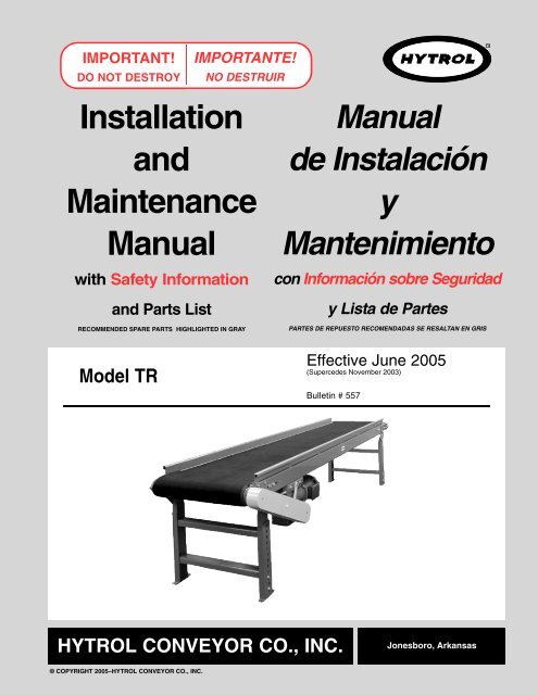
IMPORTANT!<br />
DO NOT DES<strong>TR</strong>OY<br />
IMPORTANTE!<br />
NO DES<strong>TR</strong>UIR<br />
I n s t a l l a t i o n<br />
a n d<br />
M a i n t e n a n c e<br />
M a n u a l<br />
with Safety Information<br />
and <strong>Parts</strong> <strong>List</strong><br />
RECOMMENDED SPARE PARTS HIGHLIGHTED IN GRAY<br />
M a n u a l<br />
de Instalación<br />
y<br />
M a n t e n i m i e n t o<br />
con Información sobre Seguridad<br />
y <strong>List</strong>a de Partes<br />
PARTES DE REPUESTO RECOMENDADAS SE RESALTAN EN GRIS<br />
<strong>Model</strong> <strong>TR</strong><br />
Effective June 2005<br />
(Supercedes November 2003)<br />
Bulletin # 557<br />
HY<strong>TR</strong>OL CONVEYOR CO., INC.<br />
Jonesboro, Arkansas<br />
© COPYRIGHT 2005–HY<strong>TR</strong>OL CONVEYOR CO., INC.
● Table of Contents<br />
Warning Signs . . . . . . . . . . . . . . . . . . . . .3<br />
IN<strong>TR</strong>ODUCTION<br />
Receiving and Uncrating . . . . . . . . . . . . .4<br />
INSTALLATION<br />
Installation Safety Precautions . . . . . . . .4<br />
Support Installation . . . . . . . . . . . . . . . . .5<br />
Ceiling Hanger Installation . . . . . . . . . . .6<br />
<strong>Conveyor</strong> Set-Up . . . . . . . . . . . . . . . . . . .7<br />
Belt Installation . . . . . . . . . . . . . . . . . . . .8<br />
Electrical Equipment . . . . . . . . . . . . . . .10<br />
OPERATION<br />
Operation Safety Precautions . . . . . . . .12<br />
<strong>Conveyor</strong> Start-Up . . . . . . . . . . . . . . . .12<br />
MAINTENANCE<br />
Maintenance Safety Precautions . . . . .13<br />
Lubrication . . . . . . . . . . . . . . . . . . . . . . .13<br />
Belt Tracking . . . . . . . . . . . . . . . . . . . . .14<br />
Drive Chain Alignment and Tension . . .17<br />
Trouble Shooting . . . . . . . . . . . . . . . . . .18<br />
Maintenance Checklist . . . . . . . . . . . . .20<br />
How To Order Replacement <strong>Parts</strong> . . . .22<br />
REPLACEMENT PARTS<br />
<strong>Model</strong> <strong>TR</strong> <strong>Parts</strong> Drawing & <strong>List</strong><br />
4” End Drive . . . . . . . . . . . . . . . . . . . . .24<br />
8” End Drive . . . . . . . . . . . . . . . . . . . . .26<br />
4” & 8” Center Drive . . . . . . . . . . . . . . .28<br />
4” Center Drive Assembly . . . . . . . . . . .30<br />
8” Center Drive Assembly . . . . . . . . . . .31<br />
Power Feeder . . . . . . . . . . . . . . . . . . . .32<br />
Underside Take-Up . . . . . . . . . . . . . . . .34<br />
● Tabla de Contenido<br />
Señales de Advertencia . . . . . . . . . . . . .3<br />
IN<strong>TR</strong>ODUCCION<br />
Recepción y Desembalaje . . . . . . . . . . .4<br />
INSTALACION<br />
Seguridad en la Instalación . . . . . . . . . . .4<br />
Instalación de los Soportes . . . . . . . . . . .5<br />
Instalación de los Soportes de Techo . . .6<br />
Montaje . . . . . . . . . . . . . . . . . . . . . . . . . .7<br />
Instalación de la Banda . . . . . . . . . . . . . .8<br />
Equipo Eléctrico . . . . . . . . . . . . . . . . . .10<br />
OPERACION<br />
Seguridad en la Operación . . . . . . . . . .12<br />
Arranque del Transportador . . . . . . . . .12<br />
MANTENIMIENTO<br />
Seguridad en el Mantenimiento . . . . . .13<br />
Lubricación . . . . . . . . . . . . . . . . . . . . . .13<br />
Alineación de la Banda . . . . . . . . . . . . .14<br />
Alineación y Tensión de la Cadena . . .17<br />
Resolviendo Problemas . . . . . . . . . . . .19<br />
Mantenimiento Preventivo . . . . . . . . . . .21<br />
Como Ordenar Partes de Repuesto . . .23<br />
PARTES DE REPUESTO<br />
Dibujos y <strong>List</strong>as de Partes del Mo. <strong>TR</strong><br />
Unidad Motriz de Extremo de 4” . . . . . .24<br />
Unidad Motriz de Extremo de 8 . . . . . .26<br />
Unidad Motriz Central de 4” y 8” . . . . . .28<br />
Ensamble de la Unidad Motriz<br />
Central de 4” . . . . . . . . . . . . . . . . . . .30<br />
Ensamble de la Unidad Motriz<br />
Central de 8” . . . . . . . . . . . . . . . . . . .31<br />
Alimentador Motriz Estándar . . . . . . . . .32<br />
Ensamble del Tensor Inferior . . . . . . . .34<br />
2
● Warning Signs<br />
In an effort to reduce the possibility of injury to personnel<br />
working around HY<strong>TR</strong>OL conveying equipment, warning<br />
signs are placed at various points on the equipment to alert<br />
them of potential dangers. Please check equipment and<br />
note all warning signs. Make certain your personnel are<br />
alerted to and obey these warnings. Shown below are typical<br />
signs that are attached to this equipment.<br />
● Señales de Advertencia<br />
En un esfuerzo por reducir la posibilidad de accidentes al<br />
personal trabajando junto al equipo de transportación<br />
HY<strong>TR</strong>OL, se colocan señales de advertencia en diferentes<br />
puntos del equipo para alertarlos de riesgos potenciales.<br />
Por favor verifique el equipo y asegúrese de ver todas las<br />
señales de advertencia. Asegúrese de que su personal esté<br />
alerta y obedezca las señales. Abajo se muestran las<br />
señales que se encuentran en este equipo.<br />
PLACED ON ALL POWERED CONVEYORS<br />
NEAR DRIVE AND/OR CON<strong>TR</strong>OLS.<br />
COLOCADA EN TODOS LOS<br />
<strong>TR</strong>ANSPORTADORES MOTORIZADOS<br />
CERCA AL MOTOR Y/O LOS CON<strong>TR</strong>OLES<br />
PLACED NEXT TO DRIVE, BOTH SIDES.<br />
COLOCADA JUNTO A LA UNIDAD MO<strong>TR</strong>IZ, EN<br />
AMBOS LADOS.<br />
PLACED ON 20 FT. INTERVALS,BOTH SIDES.<br />
COLOCADA EN INTERVALOS DE 20 PIES, A AMBOS LADOS.<br />
PLACED ON ALL CHAIN GUARDS.<br />
COLOCADA EN TODAS LAS GUARDA CADENAS.<br />
PLACED ON TERMINATING ENDS.<br />
COLOCADA EN LOS EX<strong>TR</strong>EMOS.<br />
PLACED AT DRIVE OF ALL POWERED CONVEYORS.<br />
COLOCADA EN LA UNIDAD MO<strong>TR</strong>IZ DE TODOS LOS<br />
<strong>TR</strong>ANSPORTADORES MOTORIZADOS.<br />
NOTE: BILINGUAL (SPANISH) LABELS AVAILABLE UPON REQUEST.<br />
NOTA: ETIQUETAS BILINGÜES (ESPAÑOL) SERÁN PROVEÍDAS<br />
BAJO PETICIÓN.<br />
3
IN<strong>TR</strong>ODUCTION<br />
I N T R O D U C C I O N<br />
This manual provides guidelines and procedures for<br />
installing, operating, and maintaining your conveyor. A<br />
complete parts list is provided with recommended spare<br />
parts highlighted in gray. Important safety information is<br />
also provided throughout the manual. For safety to personnel<br />
and for proper operation of your conveyor, it is recommended<br />
that you read and follow the instructions provided<br />
in this manual.<br />
Este manual provee las pautas y los procedimientos para<br />
instalar, operar, y mantener su transportador. Se propor -<br />
ciona una lista completa de repuestos, de los cuales, los<br />
recomendados, estarán resaltados en gris. También se pro -<br />
porciona información importante de seguridad a lo largo de<br />
este manual. Para seguridad del personal y para un fun -<br />
cionamiento apropiado del transportador, se recomienda<br />
que lea y siga las instrucciones proporcionadas en este<br />
manual.<br />
● Receiving and Uncrating<br />
1. . . Check the number of items received against the bill of<br />
lading.<br />
2. . . Examine condition of equipment to determine if any<br />
damage occurred during shipment.<br />
3. . . Move all crates to area of installation.<br />
4. . . Remove crating and check for optional equipment that<br />
may be fastened to the conveyor. Make sure these<br />
parts (or any foreign pieces) are removed.<br />
● Recepción y Desembalaje<br />
1. . . Verifique el número de partes recibidas con el<br />
conocimiento del embarque.<br />
2. . . Examine las condiciones del equipo para determinar si<br />
algún daño ha ocurrido durante la transportación.<br />
3. . . Mueva todo el equipo hacia el área de instalación.<br />
4. . . Remueva todos los empaques y verifique si hay partes<br />
opcionales que deben estar atadas al equipo.<br />
Asegúrese de que estas partes (o cualquier otras<br />
partes externas) sean removidas.<br />
NOTE: If damage has occurred or freight is missing, see<br />
the “Important Notice” attached to the crate.<br />
NOTA: Si algún daño ha ocurrido o falta cargamento,<br />
vea las “Notas Importantes” adheridas al embalaje.<br />
4<br />
INSTALLATION<br />
● Installation Safety<br />
Precautions for <strong>Conveyor</strong>s<br />
and Related Equipment<br />
GUARDS AND GUARDING<br />
Interfacing of Equipment. When two or more pieces of<br />
equipment are interfaced, special attention shall be given to<br />
the interfaced area to insure the presence of adequate<br />
guarding and safety devices.<br />
Guarding Exceptions. Wherever conditions prevail that<br />
would require guarding under these standards, but such<br />
guarding would render the conveyor unusable, prominent<br />
warning means shall be provided in the area or on the<br />
equipment in lieu of guarding.<br />
Guarded by Location or Position. Where necessary for<br />
the protection of employees from hazards, all exposed moving<br />
machinery parts that present a hazard to employees at<br />
their work station shall be mechanically or electrically guarded,<br />
or guarded by location or position.<br />
When a conveyor passes over a walkway, roadway, or work<br />
station, it is considered guarded solely by location or position<br />
if all moving parts are at least 8 ft. (2.44 m) above the<br />
floor or walking surface or are otherwise located so that the<br />
INSTALACION<br />
● Medidas de Seguridad<br />
al Instalar Transportadores<br />
y Equipos Relacionados<br />
GUARDAS Y PROTECCIONES<br />
Unión del Equipo. Cuando dos o más piezas del equipo<br />
van unidas, debe ponerse especial atención al área de<br />
unión para asegurar que las guardas adecuadas y los dis -<br />
positivos de seguridad estén presentes.<br />
Excepciones de Protección. Dondequiera que las<br />
guardas sean necesarias, pero que la colocación de las<br />
mismas inhabilite el uso del transportador, se propor -<br />
cionarán señales de advertencia visibles en el área o en el<br />
equipo en vez de las guardas.<br />
Protección dada por Posición o Ubicación. Cuando sea<br />
necesaria la protección de los empleados contra posibles<br />
riesgos, todas las partes del equipo que estén expuestas y<br />
en movimiento, y que puedan presentar un peligro para<br />
ellos en sus puestos de trabajo, serán protegidas mecánica<br />
o eléctricamente, o protegidas por su posición o ubicación.<br />
Cuando el transportador está instalado sobre pasillos,<br />
corredores o puestos de trabajo, se considera protegido<br />
únicamente por localización o posición si todas las partes
employee cannot inadvertently come in contact with hazardous<br />
moving parts.<br />
Although overhead conveyors may be guarded by location,<br />
spill guard, pan guards, or equivalent shall be provided if the<br />
product may fall off the conveyor for any reason and if personnel<br />
would be endangered.<br />
HEADROOM<br />
When conveyors are installed above exit passageways,<br />
aisles, or corridors, there shall be provided a minimum<br />
clearance of 6 ft. 8 in. (2.032 m) measured vertically from<br />
the floor or walking surface to the lowest part of the conveyor<br />
or guards.<br />
Where system function will be impaired by providing the<br />
minimum clearance of 6 ft. 8 in. (2.032 m) through an emergency<br />
exit, alternate passageways shall be provided.<br />
It is permissible to allow passage under conveyors with less<br />
than 6 ft. 8 in. (2.032 m) clearance from the floor for other<br />
than emergency exits if a suitable warning indicates low<br />
headroom.<br />
en movimiento están mínimo a 8 pies (2.44m) de altura del<br />
piso, o si está localizado de tal manera que el empleado no<br />
pueda entrar en contacto inadvertidamente con dichas<br />
partes.<br />
A pesar de que los transportadores áereos pueden estar<br />
protegidos por su localización, guardas laterales e<br />
inferiores deben ser proporcionadas para evitar que el pro -<br />
ducto se caiga del transportador y así mantener al per -<br />
sonal fuera de peligro.<br />
UBICACION SUPERIOR<br />
Cuando los transportadores son instalados sobre pasillos o<br />
corredores de salida, debe dejarse un espacio libre de<br />
mínimo 6 pies 8 pulgadas (2,032m) de extensión, medido<br />
verticalmente desde el piso o área de tránsito hasta la parte<br />
más baja del transportador o de las guardas.<br />
Si se proporcionan señales de advertencia adequadas indi -<br />
cando baja altura; es posible dejar espacio libre con menos<br />
de 6 pies 8 pulgadas (2.032m) de extensión entre el piso y<br />
el transportador en los pasillos que no sean salidas de<br />
emergencia.<br />
● Support Installation<br />
1. . . Determine primary direction of product flow. Figure 5A<br />
indicates the preferred flow as related to the drive.<br />
2. . . Refer to “Match-Mark” numbers on ends of conveyor<br />
sections. (Figure 5A).<br />
3. . . Attach supports to both ends of drive section and to<br />
one end of intermediate or tail sections (Figure 5A).<br />
Hand tighten bolts only at this time.<br />
4. . . Adjust elevation to required height.<br />
● Instalación de los Soportes<br />
1. . . Determine la dirección primaria del flujo del producto.<br />
La figura 5A indica el flujo preferido en relación con la<br />
unidad motriz.<br />
2. . . Refiérase a las “Etiquetas de Secuencia de Armado”<br />
situadas al final de las secciones del transportador.<br />
(Figura 5A).<br />
3. . . Fije los soportes en ambos extremos de la sección<br />
motriz y a un extremo de la sección intermedia o final<br />
(Figura 5A). Apriete los tornillos manualmente.<br />
4. . . Ajuste la elevación a la altura requerida.<br />
FIGURE 5A<br />
5
● Ceiling Hanger<br />
Installationcho<br />
If conveyors are to be used in an overhead application,<br />
ceiling hangers may have been supplied in place of floor<br />
supports.<br />
Figure 6A shows how a ceiling hanger mounts to a conveyor<br />
section. Ceiling hangers should be mounted at section<br />
joints. For safety information concerning conveyors<br />
mounted overhead, refer to “Installation Safety<br />
Precautions” on Page 4.<br />
● Instalación de los<br />
Soportes de Techo<br />
Si los transportadores van a ser usados en aplicaciones<br />
aéreas o superiores, soportes de techo pudieron haber<br />
sido suministrados en vez de los soportes de piso.<br />
La Figura 6A muestra como un soporte de techo se instala<br />
en un transportador. Los soportes deben montarse en la<br />
unión de las secciones. Para información de seguridad<br />
respecto al montaje de transportadores aéreos, refiérase a<br />
“Medidas de Seguridad al Instalar” en la página 4.<br />
NOTE: When installing ceiling hanger rods in an existing<br />
building, all methods of attachment must comply with<br />
local building codes.<br />
NOTA: Cuando se instalan varillas colgantes al techo en<br />
una construcción existente, todos los métodos de unión<br />
deben cumplir con los códigos locales de construcción.<br />
FIGURE 6A<br />
6
● <strong>Conveyor</strong> Set-Up<br />
1. . . Mark a chalk line on floor to locate center of the conveyor<br />
(Floor Mounted <strong>Conveyor</strong>s).<br />
2. . . Place the drive section in position.<br />
3. . . Install remaining sections placing end without support<br />
on extend support of previous section (Figure 7A).<br />
Check “Match Mark” Numbers to see that adjoining<br />
sections are in proper sequence<br />
4. . . Fasten sections together with splice plates and pivot<br />
plates (Figure 7B). Hand tighten bolts only.<br />
5. . . Check to see that conveyor is level across width and<br />
length of unit. Adjust supports as necessary.<br />
6. . . Tighten all splice plates and support mounting bolts<br />
and lag to the floor.<br />
7. . . Install electrical controls and wire motor. See Page<br />
10.<br />
8. . . Install and track belt per instructions on Pages 8 and<br />
14.<br />
● Montaje<br />
1. . . Marque con tiza una línea en el suelo para ubicar el<br />
centro del transportador. (Solamente para los<br />
Transportadores Montados en el Piso).<br />
2. . . Coloque la sección motriz en posición.<br />
3. . . Instale las secciones restantes, colocando el extremo<br />
sin soporte en la placa pivote de la sección anterior<br />
(Figura 7A). Revise las etiquetas de secuencia de<br />
armado y asegurese de que las secciones están en el<br />
orden correcto.<br />
4. . . Sujete las secciones con placas de unión y placas<br />
pivote (Figura 7B). Apriete los tornillos manualmente.<br />
5. . . Revise si el transportador está nivelado a lo ancho y<br />
largo de la unidad. Ajuste los soportes como sea<br />
necesario.<br />
6. . . Apriete todas las placas de union y los tornillos de<br />
montaje. Ancle el transportador al piso.<br />
7. . . Instale los controles eléctricos y conecte el motor<br />
(Pag. 10).<br />
8. . . Instale y alinie la banda con las instrucciones de las<br />
Páginas 8 y 14.<br />
FIGURE 7A<br />
FIGURE 7B<br />
7
● Belt Installation<br />
The conveyor belt has been cut to the proper length and lacing<br />
installed at the factory. To install follow these steps:<br />
● Instalación de la Banda<br />
La banda del transportador ha sido previamente cortada y<br />
enlazada en la fábrica. Para instalarla siga los siguientes<br />
pasos:<br />
1. . . Thread belt through conveyor as shown in Figure 9B.<br />
2. . . Pull ends together and insert lacing pin (Figure 9A). If<br />
belts ends cannot be pulled together by hand, loosen<br />
take-ups (in center drive or at tail pulley) and/or use a<br />
belt puller so lacing pin can be inserted.<br />
3. . . Adjust belt tension with take-up pulley or tail pulley.<br />
Keep pulley square by moving both take-up bolts an<br />
equal amount. Maintain enough tension so drive pulley<br />
will not slip when carrying the rated load.<br />
4. . . Track belt per instructions on Page14.<br />
1. . . Coloque la banda a través del transportador (Fig. 9B).<br />
2. . . Junte los extremos e incerte el pasador de enlace (Fig.<br />
9A). Si los extremos no se pueden juntar manualmente<br />
afloje los tensores (en el motor central o en la polea de<br />
retorno) y/o use un jalador para que el pasador pueda<br />
ser incertado.<br />
3. . . Ajuste la tensión de la banda con las poleas tensoras<br />
o con la polea de retorno. Mantenga la polea<br />
encuadrada moviendo los tornillos tensores a la misma<br />
distancia. Mantenga suficiente tension para que la<br />
polea motriz no se resvale cuando transporte la carga<br />
estimada.<br />
4. . . Alinie la banda de acuerdo a las instrucciones de la<br />
página 14.<br />
NOTE: If belt ends cannot be pulled together by hand,<br />
it may be necessary to loosen take-ups (at tail pulley,<br />
etc.), minimum position or use a belt puller so lacing<br />
pin can be easily inserted.<br />
NOTA: Si los extremos de la banda no pueden ser<br />
unidos manualmente, afloje los tornillos tensores (en<br />
la polea de retorno, etc.) ó puede usar un jalador de<br />
banda hasta que el pasador pueda ser facilmente<br />
insertado.<br />
CAUTION!<br />
Excessive slippage will reduce belt life and damage<br />
drive pulley lagging. Never apply more tension than is<br />
needed.<br />
Over-tension will cause extra wear to belt and bearings<br />
and will require extra power from drive.<br />
¡ P R E C A U C I O N !<br />
El patinaje excesivo reducirá la vida de la banda y<br />
dañará el revestimiento de la polea motriz. Nunca<br />
aplique mas tensión de la necesaria. Una sobre-tensión<br />
causará un desgaste extra de la banda y los rodamien -<br />
tos, y requerirá una mayor potencia de la unidad motriz.<br />
8
FIGURE 9A<br />
FIGURE 9B<br />
BELT INSTALLATION—END DRIVE<br />
(INSTALACION DE LA BANDA—UNIDAD MO<strong>TR</strong>IZ DE EX<strong>TR</strong>EMO)<br />
BELT INSTALLATION—CENTER DRIVE OR UNDERSIDE TAKE UP<br />
(INSTALACION DE LA BANDA—UNIDAD MO<strong>TR</strong>IZ CEN<strong>TR</strong>AL O TENSORES INFERIORES)<br />
9
● Electrical Equipment<br />
WARNING!<br />
Electrical controls shall be installed and wired by a<br />
qualified electrician. Wiring information for the motor<br />
and controls are furnished by the equipment manufacturer.<br />
CON<strong>TR</strong>OLS<br />
Electrical Code: All motor controls and wiring shall conform<br />
to the National Electrical Code (Article 670 or other applicable<br />
articles) as published by the National Fire Protection<br />
Association and as approved by the American Standards<br />
Institute, Inc.<br />
CON<strong>TR</strong>OL STATIONS<br />
A) Control stations should be so arranged and located that<br />
the operation of the equipment is visible from them, and<br />
shall be clearly marked or labeled to indicate the function<br />
controlled.<br />
B) A conveyor which would cause injury when started shall<br />
not be started until employees in the area are alerted by a<br />
signal or by a designated person that the conveyor is about<br />
to start.<br />
When a conveyor would cause injury when started and<br />
is automatically controlled or must be controlled from a<br />
remote location, an audible device shall be provided which<br />
can be clearly heard at all points along the conveyor where<br />
personnel may be present. The warning device shall be<br />
actuated by the controller device starting the conveyor and<br />
shall continue for a required period of time before the conveyor<br />
starts. A flashing light or similar visual warning may be<br />
used in conjunction with or in place of the audible device if<br />
more effective in particular circumstances.<br />
Where system function would be seriously hindered or<br />
adversely affected by the required time delay or where the<br />
intent of the warning may be misinterpreted (i.e., a work<br />
area with many different conveyors and allied devices),<br />
clear, concise, and legible warning shall be provided. The<br />
warning shall indicate that conveyors and allied equipment<br />
may be started at any time, that danger exists, and that personnel<br />
must keep clear. The warnings shall be provided<br />
along the conveyor at areas not guarded by position or location.<br />
C) Remotely and automatically controlled conveyors, and<br />
conveyors where operator stations are not manned or are<br />
beyond voice and visual contact from drive areas, loading<br />
areas, transfer points, and other potentially hazardous locations<br />
on the conveyor path not guarded by location, position,<br />
or guards, shall be furnished with emergency stop buttons,<br />
pull cords, limit switches, or similar emergency stop<br />
devices.<br />
● Equipo Eléctrico<br />
ADVERTENCIA!<br />
Los controles eléctricos deben ser conectados e insta -<br />
lados por un electricista calificado. La información sobre<br />
el cableado del motor y los controles será proporcionada<br />
por el fabricante del equipo.<br />
C O N T R O L E S<br />
Código Eléctrico: Todos los controles del motor y las<br />
conexiones deben ajustarse al “National Electrical Code“<br />
(Artículo 670 u otros artículos aplicables) como fue publicado<br />
por la “National Fire Protection Association” y aprobado por el<br />
“American Standards Institute, Inc.”<br />
E S TACIONES DE CON<strong>TR</strong>OL<br />
A) Las estaciones de control deberán estar arregladas y ubi -<br />
cadas de tal forma que el funcionamiento del equipo sea visible<br />
y deberán estar claramente marcadas o señaladas para<br />
indicar la función controlada.<br />
B) Un transportador que pueda causar lesiones cuando es<br />
puesto en marcha, no deberá ponerse en funcionamiento<br />
hasta que los trabajadores en el área sean alertados por una<br />
señal o por una persona designada que indique que el trans -<br />
portador está a punto de arrancar.<br />
Cuando un transportador pueda causar lesiones al arran -<br />
car y es automáticamente controlado, o tiene que ser contro -<br />
lado desde una ubicación lejana, se deberá proporcionar un<br />
dispositivo sonoro el cual pueda ser escuchado claramente en<br />
todos los puntos a lo largo del transportador donde el per -<br />
sonal pueda estar presente. El dispositivo de advertencia<br />
deberá ser activado por el dispositivo de arranque del trans -<br />
portador y deberá continuar sonando por un determinado<br />
periodo de tiempo antes de que el transportador empiece a<br />
f u n c i o n a r. Una luz intermitente o una advertencia visual simi -<br />
lar puede ser utilizada con o en lugar del dispositivo sonoro si<br />
es más efectivo en circunstancias particulares.<br />
Donde el funcionamiento del sistema pudiera ser<br />
seriamente obstruido o adversamente afectado por el tiempo<br />
de retardo requerido, o donde el intento de advertencia pueda<br />
ser mal interpretado (ej., un área de trabajo con diversas<br />
líneas de transportadores y los dispositivos de advertencia<br />
relacionados), advertencias claras, concisas y legibles<br />
deberán ser proporcionadas. Las advertencias deberán indicar<br />
que los transportadores y los equipos relacionados pueden ser<br />
puestos en marcha en cualquier momento, que existe un peli -<br />
gro y que el personal debe mantenerse alejado. Estas adver -<br />
tencias deben ser proporcionadas a lo largo del transportador<br />
en áreas que no sean protegidas por la posición o la ubicación.<br />
C ) Los transportadores controlados automáticamente y desde<br />
estaciones lejanas, y los transportadores donde las estaciones<br />
de funcionamiento no estén controladas por una persona o<br />
10
All such emergency stop devices shall be easily identifiable<br />
in the immediate vicinity of such locations unless<br />
guarded by location, position, or guards. Where the design,<br />
function, and operation of such conveyor clearly is not hazardous<br />
to personnel, an emergency stop device is not<br />
required.<br />
The emergency stop device shall act directly on the control<br />
of the conveyor concerned and shall not depend on the<br />
stopping of any other equipment. The emergency stop<br />
devices shall be installed so that they cannot be overridden<br />
from other locations.<br />
D) Inactive and unused actuators, controllers, and wiring<br />
should be removed from control stations and panel boards,<br />
together with obsolete diagrams, indicators, control labels,<br />
and other material which serve to confuse the operator.<br />
SAFETY DEVICES<br />
A) All safety devices, including wiring of electrical safety<br />
devices, shall be arranged to operate in a “Fail-Safe” manner,<br />
that is, if power failure or failure of the device itself<br />
would occur, a hazardous condition must not result.<br />
B) Emergency Stops and Restarts. <strong>Conveyor</strong> controls shall<br />
be so arranged that, in case of emergency stop, manual<br />
reset or start at the location where the emergency stop was<br />
initiated, shall be required of the conveyor(s) and associated<br />
equipment to resume operation.<br />
C) Before restarting a conveyor which has been stopped<br />
because of an emergency, an inspection of the conveyor<br />
shall be made and the cause of the stoppage determined.<br />
The starting device shall be locked out before any attempt<br />
is made to remove the cause of stoppage, unless operation<br />
is necessary to determine the cause or to safely remove the<br />
stoppage.<br />
Refer to ANSI Z244.1-1982, American National Standard for<br />
Personnel Protection – Lockout/Tagout of Energy Sources<br />
– Minimum Safety Requirements and OSHA Standard<br />
Number 29 CFR 1910.147 “The Control of Hazardous<br />
Energy (Lockout/Tagout).”<br />
estén mas allá del alcance de la voz y del contacto visual de<br />
las áreas de conducción, áreas de carga, puntos de transferencia<br />
y otros sitios potencialmente peligrosos localizados<br />
en la trayectoria del transportador que no tenga protección,<br />
ya sea dada por posición, ubicación, o guardas, deberán ser<br />
equipados con interruptores de parada de emergencia, cor -<br />
dones de parada de emergencia, interruptores de límite o<br />
dispositivos similares para paradas de emergencia.<br />
Todos estos dispositivos de parada de emergencia<br />
deberán ser fácilmente identificables en las cercanías<br />
inmediatas a estos puntos potencialmente peligrosos, a no<br />
ser que estén protegidos dada su ubicación, posición o pro -<br />
tegidos con guardas. Donde el diseño, el funcionamiento, y<br />
la operación de tales transportadores no represente un claro<br />
peligro para el personal, no se requieren los despositivos de<br />
parada de emergencia.<br />
El dispositivo de parada de emergencia deberá actuar<br />
directamente en el control del transportador concerniente y<br />
no deberá depender de la parada de cualquier otro equipo.<br />
Los dispositivos de parada de emergencia deberán ser insta -<br />
lados de tal forma que no puedan ser anulados desde otras<br />
l o c a l i d a d e s .<br />
D) Los controles, los actuadores inactivos o no usados y los<br />
cables, deberán ser removidos de las estaciones de control<br />
y de los tableros de mando, junto con los diagramas, indi -<br />
cadores, etiquetas de control y otros materiales obsoletos,<br />
los cuales se prestan para confundir al operador.<br />
DISPOSITIVOS DE SEGURIDAD<br />
A) Todos los dispositivos de seguridad, incluyendo la<br />
conexión de dispositivos eléctricos, deben ser dispuestos<br />
para operar en una manera de “autoprotección”; es decir, si<br />
se presenta una pérdida de corriente o un fallo en el mismo<br />
dispositivo, no debe presentarse una situación peligrosa.<br />
B) Paradas de Emergencia y Reactivadores. Los controles<br />
del transportador deberán estar dispuestos de tal manera<br />
que en caso de una parada de emergencia, se requerirá un<br />
activador o arrancador manual en la ubicación donde la<br />
parada de emergencia se presenta para reanudar la<br />
operación del transportador o transportadores y el equipo<br />
a s o c i a d o .<br />
C) Antes de volver a poner en marcha un transportador que<br />
haya sido detenido por una emergencia, debe revisarse y<br />
determinar la causa de la parada. El dispositivo de arranque<br />
deberá ser bloqueado antes de intentar corregir o remover la<br />
causa que originó la parada, a no ser que la operación del<br />
transportador sea necesaria para determinar la causa o para<br />
solucionar el problema de la parada sin ningún peligro.<br />
Refiérase a ANSI Z244.1-1982, “American National<br />
Standard for Personnel Protection” - Lockout/Tagout of<br />
Energy Sources - Minimum Safety Requirements and OSHA<br />
Standard Number 29 CFR 1910.147 “The Control of<br />
Hazardous Energy (Lockout/Ta g o u t ) . ”<br />
11
O P E R AT I O N<br />
O P E R A C I O N<br />
● Operation Safety Precautions<br />
A ) Only trained employees shall be permitted to operate conveyors.<br />
Training shall include instruction in operation under normal conditions and<br />
emergency situations.<br />
B ) Where employee safety is dependent upon stopping and/or starting<br />
devices, they shall be kept free of obstructions to permit ready access.<br />
C ) The area around loading and unloading points shall be kept clear of<br />
obstructions which could endanger personnel.<br />
D ) No person shall ride the load-carrying element of a conveyor under any<br />
circumstances unless that person is specifically authorized by the owner<br />
or employer to do so. Under those circumstances, such employee shall<br />
only ride a conveyor which incorporates within its supporting structure,<br />
platforms or control stations specifically designed for carrying personnel.<br />
Under no circumstances shall any person ride on any element of a vertical<br />
conveyor. Owners of conveyors should affix warning devices to the<br />
conveyor reading Do Not Ride <strong>Conveyor</strong>.<br />
E) Personnel working on or near a conveyor shall be instructed as to the<br />
location and operation of pertinent stopping devices.<br />
F ) A conveyor shall be used to transport only material it is capable of handling<br />
safely.<br />
G ) Under no circumstances shall the safety characteristics of the conveyor<br />
be altered if such alterations would endanger personnel.<br />
H ) Routine inspections and preventive and corrective maintenance programs<br />
shall be conducted to insure that all safety features and devices are<br />
retained and function properly.<br />
I ) Personnel should be alerted to the potential hazard of entanglement in<br />
conveyors caused by items such as long hair, loose clothing, and jewelry.<br />
J ) As a general rule, conveyors should not be cleaned while in operation.<br />
Where proper cleaning requires the conveyor to be in motion and a hazard<br />
exists, personnel should be made aware of the associated hazard.<br />
● Medidas de Seguridad<br />
A) Solo se debe permitir operar los transportadores a empleados entrenados.<br />
El entrenamiento debe incluir instrucciones de operación bajo condiciones<br />
normales y en situaciones de emergencia.<br />
B ) Donde la seguridad de los trabajadores dependa de dispositivos de para -<br />
da y/o arranque, éstos deberán mantenerse libres de obstrucciones para per -<br />
mitir un acceso rápido.<br />
C ) El área alrededor de los puntos de carga y descarga debe mantenerse<br />
libre de obstrucciones, las cuales podrían poner en peligro al personal.<br />
D ) Ninguna persona debe montarse en la parte de conducción de carga de<br />
un transportador bajo ninguna circunstancia al menos que esta persona esté<br />
específicamente autorizada por el dueño o por el supervisor. Bajo estas cir -<br />
cunstancias, el empleado deberá montarse solamente en un transportador<br />
que tenga incorporado dentro de su estructura, plataformas o estaciones de<br />
control especialmente diseñadas para el traslado de personal. Bajo ninguna<br />
circunstancia, persona alguna debe subirse en cualquier parte de un trans -<br />
portador vertical. Los dueños de los transportadores deben añadir señales de<br />
advertencia al transportador con el texto: “No Montarse en el Tr a n s p o r t a d o r ” .<br />
E ) El personal que esté trabajando en o cerca al transportador, deberá ser<br />
instruído en cuanto a la ubicación y operación de los dispositivos pertinentes<br />
de parada.<br />
F ) Un transportador deberá ser usado para transportar solo los productos que<br />
sea capaz de manejar seguramente.<br />
G ) Bajo ninguna circunstancia deberán ser alteradas las características de<br />
seguridad de un transportador, si tales alteraciones pudieran poner en peligro<br />
al personal.<br />
H) Inspecciones rutinarias deberán llevarse a cabo al igual que programas<br />
preventivos y correctivos de mantenimiento, para asegurar que todos los dis -<br />
positivos y medidas de seguridad sean conservados en buen estado y fun -<br />
cionen correctamente.<br />
I ) El personal deberá ser avisado de peligros potenciales como enredos en<br />
transportadores causados por materiales como cabello largo, ropa suelta o<br />
j o y a s .<br />
J ) Como regla general, los transportadores no deberán limpiarse mientras<br />
estén en funcionamiento. Cuando se requiera limpiar el transportador<br />
estando en movimiento y exista posibilidad de peligro, el personal deberá ser<br />
avisado de este riesgo.<br />
12<br />
● <strong>Conveyor</strong> Start-Up<br />
Before conveyor is turned on, check for foreign objects that may<br />
have been left inside conveyor during installation. These objects<br />
could cause serious damage during start-up.<br />
After conveyor has been turned on and is operating, check motors,<br />
reducers, and moving parts to make sure they are working freely.<br />
CAUTION!<br />
Because of the many moving parts on the conveyor, all<br />
personnel in the area of the conveyor need to be<br />
warned that the conveyor is about to be started.<br />
●Arranque del Transportador<br />
Antes de poner en marcha el transportador, revise si hay objetos<br />
ajenos que puedan haber sido dejados dentro del transportador<br />
durante la instalación. Estos objetos pueden causar serios daños<br />
en el arranque.<br />
Después de que el transportador arranque y esté operando, revise<br />
los motores, reductores y partes en movimiento para estar seguro<br />
de que están trabajando libremente.<br />
PRECAUCION!<br />
Debido a la cantidad de partes en movimiento del trans -<br />
portador, todo el personal en el área del transportador<br />
necesita ser advertido de que este está a punto de<br />
ponerse en marcha.
M A I N T E N A N C E<br />
M A N T E N I M I E N TO<br />
● Maintenance Safety<br />
Precautions<br />
A ) Maintenance, such as lubrication and adjustments, shall be performed<br />
only by qualified and trained personnel.<br />
B ) It is Important that a maintenance program be established to<br />
insure that all conveyor components are maintained in a condition<br />
which does not constitute a hazard to personnel.<br />
C ) When a conveyor is stopped for maintenance purposes, starting<br />
devices or powered accessories shall be locked or tagged out in accordance<br />
with a formalized procedure designed to protect all person or<br />
groups involved with the conveyor against an unexpected start.<br />
D ) Replace all safety devices and guards before starting equipment<br />
for normal operation.<br />
E ) Whenever practical, DO NOT lubricate conveyors while they are<br />
in motion. Only trained personnel who are aware of the hazard of the<br />
conveyor in motion shall be allowed to lubricate.<br />
S A F E T Y G U A R D S<br />
Maintain all guards and safety devices IN POSITION and IN SAFE<br />
R E PA I R .<br />
WARNING SIGNS<br />
Maintain all warning signs in a legible condition and obey all warnings.<br />
See Page 3 of this manual for examples of warning signs.<br />
● Lubrication<br />
The drive chain is pre-lubricated from the manufacturer by a hot dipping<br />
process that ensures total lubrication of all components.<br />
H o w e v e r, continued proper lubrication will greatly extend the useful life<br />
of every drive chain.<br />
Drive Chain lubrication serves several purposes including:<br />
• Protecting against wear of the pin-bushing joint<br />
• Lubricating chain-sprocket contact surfaces<br />
• Preventing rust or corrosion<br />
For normal operating environments, lubricate every 2080 hours of<br />
operation or every 6 months, whichever comes first. Lubricate with a<br />
good grade of non-detergent petroleum or synthetic lubricant (i.e.,<br />
Mobile 1 Synthetic). For best results, always use a brush to generously<br />
lubricate the chain. The proper viscosity of lubricant greatly<br />
a ffects its ability to flow into the internal areas of the chain. Refer to<br />
the table below for the proper viscosity of lubricant for your application.<br />
Ambient Temperature SAE ISO<br />
Degrees F<br />
20-40 20 46 or 68<br />
40-100 30 100<br />
100-120 40 150<br />
The drive chain’s lubrication requirement is greatly affected by the<br />
operating conditions. For harsh conditions such as damp environments,<br />
dusty environments, excessive speeds, or elevated temperatures,<br />
it is best to lubricate more frequently. It may be best, under<br />
these conditions, to develop a custom lubrication schedule for your<br />
specific application. A custom lubrication schedule may be developed<br />
by inspecting the drive chain on regular time intervals for suff i c i e n t<br />
lubrication. Once the time interval is determined at which the chain is<br />
not sufficiently lubricated, lubricate it and schedule the future lubrication<br />
intervals accordingly.<br />
● Medidas de Seguridad<br />
en el Mantenimiento<br />
A ) El mantenimiento, tal como lubricación y ajustes, debe ser realizado sola -<br />
mente por personal calificado y entrenado.<br />
B ) Es importante que se establezca un programa de mante- nimiento, para<br />
asegurar que todos los componentes del transportador sean mantenidos en<br />
condiciones que no constituyan un peligro para el personal.<br />
C ) Cuando un transportador esté parado por razones de mante-nimiento,<br />
los dispositivos de arranque o accesorios motorizados deberán ser asegu -<br />
rados o desconectados conforme a un procedimiento formalizado, dis -<br />
eñado para proteger de cualquier arranque inesperado a toda persona o<br />
grupos de personas involucrados con el transportador, de un arranque ines -<br />
p e r a d o .<br />
D ) Antes de poner en marcha el equipo en una operación normal, vuelva a<br />
colocar todos los dispositivos de seguridad y las guardas.<br />
E ) Siempre que sea práctico, N O lubrique los transportadores mientras se<br />
encuentren en movimiento. Solo el personal entrenado, que tenga<br />
conocimiento de los peligros del transportador en movimiento, se le permi -<br />
tirá hacer la lubricación.<br />
PROTECCIONES DE SEGURIDAD<br />
Mantenga todas las guardas y dispositivos de seguridad EN SU POSICION<br />
y EN BUENAS CONDICIONES.<br />
SEÑALES DE A D V E RT E N C I A<br />
Mantenga todas las señales de advertencia en condiciones legibles y<br />
obedézcalas. Remítase a la página 3 de este manual para ver ejemplos de<br />
señales de advertencia.<br />
● Lubricación<br />
La cadena motriz ha sido pre-lubricada por el fabricante mediante un pro -<br />
ceso de sumersión caliente que asegura una lubricación total de todos sus<br />
componentes. Sin embargo, una lubricación apropiada y continua exten -<br />
derá su vida útil considerablemente.<br />
La lubricación de la cadena motriz cumple varios propósitos:<br />
• Proteger contra el desgaste de la unión de pines de la cadena<br />
• Lubricar las superficies de contacto entre la cadena<br />
y la catarina<br />
• Prevenir la oxidación o corrosión.<br />
En operaciones bajo condiciones ambientales normales, lubrique cada<br />
2080 horas de operación o cada 6 meses, lo que ocurra primero. Lubrique<br />
con un lubricante sintético (ej. Mobile 1 sintético) o basado en petroleo nodetergente<br />
de buen grado. Para mejores resultados, siempre utilice una<br />
brocha para lubricar la cadena generosamente. La viscosidad apropiada<br />
del lubricante afecta enormente el fluido del mismo hacia las áreas internas<br />
de la cadena. Refiérase a la siguiente tabla para consultar la viscosidad de<br />
lubricante adecuada para su aplicación.<br />
Temperatura A m b i e n t e S A E I S O<br />
(Grados Fº) (Grados Cº)<br />
20 - 40 -07 – 04 20 46 o 68<br />
40 - 100 04 – 38 30 100<br />
100 - 120 38 – 49 40 150<br />
El requerimiento de lubricación de la cadena motriz se vé afectado con -<br />
siderablemente por las condiciones de operación. En condiciones difíciles<br />
tales como: ambientes humedos, ambientes con polvo, velocidades exce -<br />
sivas, o temperaturas elevadas, se recomienda lubricar la cadena con más<br />
frecuencia. Lo mejor sería que bajo estas condiciones se establezca un pro -<br />
grama de lubricación específico para su aplicación. Este programa especí -<br />
fico puede desarrollarse mediante la inspección de la lubricación de la<br />
cadena motriz en intervalos regulares de tiempo. Una vez se ha determi -<br />
nado el intervalo en el cual la cadena no se encuentra suficientemente lubri -<br />
cada, lubríquela y programe los siguientes intervalos de acuerdo al interva -<br />
lo anterior.<br />
13
● Belt Tracking<br />
HOW IS THE CONVEYOR BELT <strong>TR</strong>ACKED<br />
The belt is tracking by adjusting: Drive Pulley, Tail Pulley,<br />
Return Idlers, and Snub Idlers. The same tracking principles<br />
apply to conveyors supplied with end drives, center drives,<br />
or underside take-ups.<br />
PRE-<strong>TR</strong>ACKING INSPECTION<br />
Before attempting to physically track the belt:<br />
1. . . Make sure conveyor is level across the width and<br />
length of unit. Adjust supports as necessary.<br />
2. . . Check to make sure: Drive Pulley, Tail Pulley, Snub<br />
Idlers, and all Return Idlers are square with conveyor<br />
bed. See illustrations 14A, 14B, 15A, 15B and 15C.<br />
Dimension “A” should be equal on both sides of unit.<br />
3. . . Make sure belt has been properly threaded through<br />
conveyor. See “Belt Installation”, Page 8.<br />
4. . . Check for improper loading. Feed should be in direction<br />
of belt travel, centered on belt.<br />
5. . . Make sure belt lacing has been installed correctly and<br />
is square with the belt.<br />
● Alineación de la Banda<br />
COMO SE ALINEA LA BANDA DEL <strong>TR</strong>ANSPORTADOR<br />
La banda se alinea al ajustar: La Polea Motriz, Polea de<br />
Retorno, Rodillos de Retorno, y Rodillos de Alineación.<br />
Los mismos principios de ajuste se aplican a los trans -<br />
portadores de unidad motriz de extremo, unidad motriz<br />
central o tensores inferiores.<br />
INSPECCION PRE-ALINEACION<br />
Antes de intentar alinear la banda:<br />
1. . . Asegúrese de que el transportador está nivelado a lo<br />
ancho y largo de la unidad. Ajuste los soportes como<br />
sea necesario.<br />
2. . . Asegúrese de que la Polea Motriz, la Polea de<br />
Retorno, y los Rodillos de Alineación y de Retorno<br />
están encuadrados con la cama del transportador<br />
(Fig. 14A a la 15C). La Dimensión “A” debe ser igual<br />
en ambos lados de la unidad.<br />
3. . . Aseguresé de que la banda haya sido propiamente<br />
colocada en el transportador. Vea “Instalación de la<br />
Banda”, Pág. 8.<br />
4. . . Revise si es cargado impropiamente. El alimentador<br />
debe estar en dirección hacia donde la banda viaja,<br />
centrado en la banda.<br />
5. . . Asegúrese de que el enlace está correctamente<br />
instalado y encuadrado con la banda.<br />
FIGURE 14A<br />
FIGURE 14B<br />
SQUARING 4” END DRIVE<br />
SQUARING 8” END DRIVE<br />
14
FIGURE 15A<br />
FIGURE 15B<br />
SQUARING RETURN PULLEY<br />
SQUARING TAIL PULLEY<br />
FIGURE 15C<br />
SQUARING PULLEYS IN CENTER DRIVE<br />
OR UNDERSIDE TAKE-UP<br />
CAUTION!<br />
Only trained personnel should track conveyor belt which<br />
must be done while conveyor is in operation.<br />
PRECAUCION!<br />
Solo el personal entrenado deberá ajustar la banda del<br />
transportador ya que se debe hacer cuando el trans -<br />
portador está operando.<br />
15
IMPORTANT: When belt tracking adjustments are made,<br />
they should be minor (1/16 in. at a time on idlers, etc.,<br />
should be sufficient.).<br />
Give the belt adequate time to react to the adjustments. It<br />
may take several complete revolutions around the conveyor<br />
for the belt to begin tracking properly on long, slow conveyor<br />
lines.<br />
A) Stand at tail pulley looking toward drive and note what<br />
direction belt is traveling.<br />
B) Having observed belt and determined tracking problem,<br />
follow procedures in “How to Steer The Belt”, See Figure<br />
16A.<br />
HOW TO STEER THE BELT<br />
Condition 1. . .When the belt is running in the direction<br />
(FLOW) with the arrow, but tracking (drifting) towards Side<br />
“X”, move the Snub Idler nearest the INFEED end of Side<br />
“Y” towards the DISCHARGE end of the conveyor.<br />
Condition 2. . . When the belt is running in the direction<br />
(FLOW) with the arrow, but tracking (drifting) towards Side<br />
“Y”, move the Snub Idler nearest the INFEED end of Side<br />
“X” towards the DISCHARGE end of the conveyor.<br />
If Belt Direction (FLOW) is reversed, all the above conditions<br />
will remain the same as in Figure 16A, except you are<br />
now viewing the conveyor from the opposite end.<br />
If belt continues to track improperly, re-check all items covered<br />
in “Pre-Tracking Inspection” and make corrections as<br />
necessary.<br />
IMPORTANTE: Cuando se hagan ajustes a la banda<br />
deberán hacerse lo menor posible (1/16” a la vez en los<br />
rodillos de retorno, etc. será suficiente).<br />
Dele a la banda el tiempo adecuado para que se ajuste. En<br />
transportadores largos y lentos, tal vez tomará varias<br />
vueltas antes de que quede ajustado.<br />
A) Párese en la polea de retorno y observe hacia que direc -<br />
ción la banda corre.<br />
B) Despues de haber observado la banda y determinado el<br />
ajuste, siga los procedimientos en “Como Dirigir la Banda”,<br />
Vea la Figura 16A.<br />
COMO DIRIGIR LA BANDA<br />
Condición 1. . .Cuando la banda está corriendo en<br />
dirección de la flecha (FLUJO), pero se desvia hacia el<br />
LADO “X”, mueva el Rodillo de Alineación más cercano del<br />
extremo de CARGA del LADO “Y” hacia el extremo de<br />
DESCARGA del transportador.<br />
Condición 2. . . Cuando la banda está corriendo en direc -<br />
ción de la flecha (FLUJO) pero se desvia hacia el LADO<br />
“Y”, mueva el Rodillo de Alineación mas cercano al extremo<br />
de CARGA del LADO “X” hacia el extremo de DESCARGA<br />
del transportador.<br />
Sí la banda corre en reversa del FLUJO, todas las condi -<br />
ciones serán las mismas (Figura 16A), exceptuando que<br />
ahora usted está viendo el transportador por el lado<br />
opuesto.<br />
Sí la banda continua estando mal alineada entonces revise<br />
todos los objetivos de la sección “Inspección Pre-<br />
Alineación” y haga las correcciones necesarias.<br />
FIGURE 16A<br />
NOTE: In all conditions, you are viewing the <strong>Conveyor</strong><br />
Belt from the INFEED end. All corrections will be made<br />
from the INFEED end of conveyor.<br />
NOTA: En todas las condiciones, el transportador se<br />
observará desde el punto de CARGA. Todas las<br />
correciones serán hechas desde este mismo punto.<br />
16
● Drive Chain Alignment<br />
and Tension<br />
The drive chain and sprockets should be checked periodically<br />
for proper tension and alignment. Improper adjustment<br />
will cause extensive wear to the drive components.<br />
TO MAKE ADJUSTMENTS<br />
1. . . Remove chain guard.<br />
2. . . Check sprocket alignment by placing a straightedge<br />
across the face of both sprockets (Figure 17A).<br />
Loosen set screws and adjust as needed. Re-tighten<br />
set screws.<br />
3. . . To adjust chain tension, loosen bolts that fasten motor<br />
base to mounting angles, both sides of the conveyor.<br />
Tighten take-up bolts until desired chain tension is<br />
reached. (Figures 17B & 17C). Re-tighten mounting<br />
bolts.<br />
4. . . Lubricate chain per lubrication instructions.<br />
5. . . Replace chain guard so that it does not interfere with<br />
drive.<br />
● Alineación y Tensión de<br />
la Cadena Motriz<br />
La cadena motriz y las catarinas deberán ser revisadas<br />
periódicamente para mantener su apropiada tensión y<br />
alineación. Ajustes incorrectos causarán un desgaste exce -<br />
sivo a los componentes de la transmisión.<br />
PARA HACER AJUSTES<br />
1. . . Remueva la guarda cadena.<br />
2. . . Verifique la alineación de las catarinas colocando un<br />
nivel sobre las caras de ambas catarinas. (Figura<br />
17A). Afloje los tornillos candados y ajuste tanto<br />
como sea necesario. Apriete los tornillos candados.<br />
3. . . Para ajustar la tensión de la cadena, afloje los tornil -<br />
los que aseguran la base del motor a los ángulos de<br />
montaje, a ambos lados del transportador.<br />
Apriete los tornillos tensores hasta obtener la tensión<br />
correcta de la cadena (Figuras 17B & 17C). Apriete<br />
los tornillos de montaje.<br />
4. . . Lubrique la cadena de acuerdo a las instrucciones de<br />
lubricación.<br />
5. . . Coloque la guarda de cadena para que no interfiera<br />
con la transmisión.<br />
FIGURE 17A<br />
CAUTION!<br />
Never remove chain<br />
guards while the conveyor<br />
is running. A l w a y s<br />
replace guards after<br />
adjustments are made.<br />
DRIVE SHAFT<br />
SPROCKET<br />
(EJE DE<br />
<strong>TR</strong>ANSMISION)<br />
S<strong>TR</strong>AIGHT EDGE<br />
(NIVEL)<br />
SET SCREWS<br />
(TORNILLOS CANDADOS)<br />
GEAR REDUCER<br />
(REDUCTOR)<br />
REDUCER<br />
SPROCKET<br />
(CATARINA DEL<br />
REDUCTOR)<br />
PRECAUCION!<br />
Nunca remueva la guar -<br />
da de cadena mientras<br />
el transportador esté en<br />
funcionamiento. Siempre<br />
vuelva a colocar las<br />
guardas después de que<br />
los ajustes se hayan<br />
hecho.<br />
FIGURE 17B<br />
FIGURE 17C<br />
MOTOR BASE PLATE<br />
(PLACA DEL MOTOR<br />
BASE)<br />
DRIVE<br />
PULLEY<br />
(POLEA<br />
MO<strong>TR</strong>IZ)<br />
MOUNTING<br />
BOLTS<br />
(TORNILLOS DE<br />
MONTAJE)<br />
TAKE-UP<br />
BOLTS<br />
(TORNILLOS<br />
TENSORES)<br />
CHAIN TOO TIGHT<br />
(REQUIRES EX<strong>TR</strong>A POWER)<br />
(CADENA DEMASIADO TENSA<br />
[REQUIERE MAS POTENCIA])<br />
SPROCKET CENTERS<br />
(CEN<strong>TR</strong>OS DE<br />
CATARINAS)<br />
CHAIN TOO LOOSE<br />
(CADENA DEMASIA -<br />
DO FLOJA)<br />
DRIVE PULLEY<br />
SPROCKET<br />
(CATARINA DE LA<br />
POLEA MO<strong>TR</strong>IZ)<br />
MOTOR/REDUC-<br />
ER DRIVE<br />
(MOTOR/REDUCTOR<br />
MO<strong>TR</strong>IZ)<br />
REDUCER<br />
SPROCKET<br />
(CATARINA DEL<br />
REDUCTOR)<br />
CORRECT SLACK<br />
(TENSION CORRECTA)<br />
APPROX. 1/4” OR<br />
2% OF SPROCKET CENTERS<br />
(1/4” O 2% DE CEN<strong>TR</strong>OS DE<br />
CATARINAS APROX.)<br />
17
● Trouble Shooting<br />
The following charts list possible problems that may occur in the operation of a powered conveyor.<br />
<strong>TR</strong>OUBLE SHOOTING DRIVES<br />
<strong>TR</strong>OUBLE CAUSE SOLUTION<br />
<strong>Conveyor</strong> will not start or motor quits frequently.<br />
Drive chain and sprockets wear excessively.<br />
Loud popping or grinding noise.<br />
Motor or reducer overheating.<br />
Belt does not move, but drive runs.<br />
1) Motor is overloaded.<br />
2) Motor is drawing too much current.<br />
1) Lack of lubrication on chain causing chain<br />
stretch which creates improper chain to<br />
sprocket mesh.<br />
2) Sprockets are out of alignment.<br />
3) Loose chain.<br />
1) Defective bearing.<br />
2) Loose set screws in bearing.<br />
3) Loose drive chain.<br />
1) <strong>Conveyor</strong> is overloaded.<br />
2) Low voltage to motor.<br />
3) Low lubricant level in reducer.<br />
1) <strong>Conveyor</strong> is overloaded.<br />
2) Belt is too loose.<br />
3) Lagging on drive pulley is worn.<br />
1) Check for overloading of conveyor.<br />
2) Check heater or circuit breaker and change if necessary.<br />
1) Replace chain and sprockets. Provide adequate lubrication.<br />
NOTE: If problem reoccurs, a chain take-up may be required.<br />
2) Align sprockets. See “Drive Chain Alignment and Tension”.<br />
3) Tighten chain.<br />
1) Replace bearing.<br />
2) Tighten set screw.<br />
3) Tighten chain.<br />
1) Check capacity of conveyor and reduce load to recommended<br />
level.<br />
2) Have electrician check and correct as necessary.<br />
3) Relubricate per manufacturer’s recommendations. For HY<strong>TR</strong>OL<br />
reducer, refer to separate manual.<br />
1) Reduce load.<br />
2) Use belt take-up to tighten belt.<br />
3) Replace drive pulley lagging and tighten belt.<br />
<strong>TR</strong>OUBLE SHOOTING DRIVE BELT <strong>TR</strong>ACKING<br />
<strong>TR</strong>OUBLE CAUSE SOLUTION<br />
Entire length of belt creeps off at one spot<br />
only.<br />
Belt creeps to one side at tail pulley.<br />
Entire belt creeps to one side.<br />
1) One or more idlers (usually near trouble<br />
spot) are out of line.<br />
2) One conveyor section not level or square.<br />
3) Material build-up on pulleys or idlers.<br />
1) Tail pulley, return idler, or snub idler near<br />
tail pulley not properly aligned or square<br />
with bed.<br />
1) <strong>Conveyor</strong> not straight.<br />
2) <strong>Conveyor</strong> not level.<br />
3) Material build-up on rollers, pulleys, or<br />
idlers.<br />
1) Adjust idlers as necessary. See “Tracking the belt” in this manual<br />
for details.<br />
2) Make necessary adjustments to supports.<br />
3) Remove residue from pulleys or idlers. install belt, cleaners, or<br />
scrappers if possible.<br />
1) Adjust as necessary. See “Belt Tracking Pre-Tracking Inspection”<br />
in this manual for details.<br />
1) Re-align bed sections as necessary.<br />
2) Correct as necessary.<br />
3) Remove residue and install belt cleaners or scrapers if possible.<br />
18
● Resolviendo Problemas<br />
Los siguientes cuadros describen posibles problemas que pueden ocurrir en la operación de un transportador motorizado.<br />
RESOLVIENDO PROBLEMAS DE <strong>TR</strong>ANSMISION<br />
PROBLEMA CAUSA SOLUCION<br />
El transportador no arranca o el motor se<br />
detiene frecuentemente.<br />
Desgaste excesivo de la cadena motriz y<br />
las catarinas.<br />
Funcionamiento muy ruidoso.<br />
Motor o reductor recalentado.<br />
La banda no se mueve, pero el motor corre.<br />
1) El motor está sobrecargado.<br />
2) El motor pasa demasiada corriente.<br />
1) Falta de lubricación en la cadena<br />
causando su extensión lo cual crea una<br />
cadena inapropiada.<br />
2) Los catarinas están desalineadas.<br />
3) La cadena está floja.<br />
1) Rodamientos defectuosos.<br />
2) El tornillo candado está flojo.<br />
3) La cadena está floja.<br />
1) Transportador está sobrecargado.<br />
2) Bajo voltaje al motor.<br />
3) Bajo nivel de lubricante en reductor.<br />
1) El transportador está sobrecargado.<br />
2) La banda está floja.<br />
3) El revestimiento de la polea motriz esta gastada.<br />
1) Revise si hay sobrecarga del transportador.<br />
2) Revise los circuitos e interruptores de protección y sobrecarga, y<br />
cámbielos si es necesario.<br />
1) Reemplaze la cadena y las catarinas. Proporcione una adecuada<br />
lubricación. NOTA: Si se presentan problemas, posiblemente se<br />
requiere tensionar la cadena.<br />
2) Alinee catarinas. Vea “Alineación y Tensión de Cadena Motriz” .<br />
3) Tensione la cadena.<br />
1) Reemplaze los baleros.<br />
2) Apriete el tornillo candado.<br />
3) Tensione la cadena.<br />
1) Revise la capacidad del transportador y reduzca la carga al nivel recomen -<br />
d a d o .<br />
2) Haga un chequeo por un electricista y corrija si es necesario.<br />
3) Vuelva a lubricar de acuerdo a las recomendaciones del fabricante.<br />
Para el reductor HY<strong>TR</strong>OL, refiérase al manual adjunto.<br />
1) Reduzca la carga.<br />
2) Use tensores de banda para apretar la banda.<br />
3) Reemplaze el revestimiento de la polea y apriete la banda.<br />
RESOLVIENDO PROBLEMAS DE ALINEACION DE LA BANDA MO<strong>TR</strong>IZ<br />
PROBLEMA CAUSA SOLUCION<br />
La banda se desliza en un punto.<br />
La banda se desliza hacia un lado en la polea<br />
de retorno.<br />
Toda la banda se desliza hacia un lado.<br />
1) Uno o más rodillos (usualmente cerca del<br />
punto del problema) están desalineados.<br />
2) Una o más secciones están desniveladas<br />
o desencuadradas.<br />
3) Acumulación de material en rodillos o<br />
poleas.<br />
1) La polea de retorno, rodillo de retorno o el rodil -<br />
lo de alineación cerca de la polea de retorno no<br />
está alineada o encuadrada con la cama.<br />
1) El transportador no está derecho.<br />
2) El transportador no está nivelado.<br />
3) Material acumulado en rodillos o poleas.<br />
1) Ajuste los rodillos como sea necesario. Use la sección “Alineación<br />
de la banda” como referencia.<br />
2) Ajuste los soportes como sea necesario.<br />
3) Remueva el residuo de los rodillos o poleas. Aplique los<br />
limpiadores de banda o raspadores si es posible.<br />
1) Ajuste como sea necesario. Vea “Inspección Pre-Alineación de la<br />
Banda” en este manual.<br />
1) Realinie las secciones de cama como sea necesario.<br />
2) Conecte como sea necesario.<br />
3) Remueva el residuo y aplique los limpiadores de banda o ras -<br />
padores si es posible.<br />
19
● Preventive Maintenance Checklist<br />
The following is a general maintenance checklist which covers the major components of your conveyor.<br />
This will be helpful in establishing a standard maintenance schedule.<br />
20
● <strong>List</strong>a de Mantenimiento Preventivo<br />
La siguiente es una lista de verificación del mantenimiento preventivo, la cual cubre los principales componentes de su trans -<br />
portador. Esta será útil para establecer un programa estándar de mantenimiento.<br />
21
● How to Order Replacement <strong>Parts</strong><br />
Included in this manual are parts drawings with complete replacement parts lists. Minor fasteners, such as nuts and bolts,<br />
are not included.<br />
When ordering replacement parts:<br />
1. . . Contact Dealer from whom conveyor was purchased<br />
or nearest HY<strong>TR</strong>OL Distributor.<br />
2. . . Give <strong>Conveyor</strong> <strong>Model</strong> Number and Serial Number or<br />
HY<strong>TR</strong>OL Factory Order Number.<br />
3. . . Give Part Number and complete description from <strong>Parts</strong><br />
<strong>List</strong>.<br />
4. . . Give type of drive. Example—8” End Drive, 8” Center<br />
Drive, etc.<br />
5. . . If you are in a breakdown situation, tell us.<br />
HY<strong>TR</strong>OL Serial Number<br />
(Located near Drive on<br />
Powered <strong>Model</strong>s).<br />
22
● Como Ordenar Partes de Repuesto<br />
Dibujo de las partes con listas completas de las refacciones están incluidos en este manual. Aseguradores menores,<br />
como tornillos y tuercas no están incluidos.<br />
Para ordenar partes de repuesto:<br />
1. . . Contacte la persona que le vendió el transportador o<br />
el distribuidor de <strong>Hytrol</strong> más cercano.<br />
2. . . Proporcione el <strong>Model</strong>o del Transportador y el Número<br />
de Serie o Número de la Orden de Fabricación.<br />
3. . . Proporcione el Número de las partes y descripción<br />
completa de la <strong>List</strong>a de Partes.<br />
4. . . Proporcione el tipo de motor. Ejemplo—Unidad Motriz<br />
de 8” en el Extremo, Unidad Motriz Central 8” , etc.<br />
5. . . Si está en una situación crítica, comuníquese<br />
inmediatamente.<br />
Número de Serie HY<strong>TR</strong>OL<br />
(Localizado cerca a la<br />
Unidad Motriz en los<br />
modelos motorizados).<br />
23
● <strong>Model</strong> <strong>TR</strong> <strong>Parts</strong> Drawing (4" End Drive)<br />
Dibujo de Partes <strong>Model</strong>o <strong>TR</strong> (4" Unidad Motriz de Extremo)<br />
BED<br />
WIDTH<br />
OAW<br />
SECTION “A-A”<br />
24
● <strong>Model</strong> <strong>TR</strong> <strong>Parts</strong> <strong>List</strong> (4" End Drive)<br />
<strong>List</strong>a de Partes del <strong>Model</strong>o <strong>TR</strong> (4" Unidad Motriz de Extremo)<br />
See Page 22 for Information on How To Order Replacement <strong>Parts</strong><br />
Vea la Página 23 para Información sobre Como Ordenar Partes de Repuesto<br />
Recommended Spare <strong>Parts</strong> Highlighted In Gray<br />
Partes de Repuesto Recomendadas se Resaltan en Gris<br />
Ref. No. Part No. Description<br />
1 — Motor—C-Face<br />
— 030.7134 1/2 HP—230/460 VAC—3 Ph.—60 Hz.—TEFC<br />
— 030.7324 1 HP—230/460 VAC—3 Ph.—60 Hz.—TEFC<br />
2 — Speed Reducer<br />
— R-00153-30R 4AC—RH—30:1 Ratio<br />
— R-00164-30R 5AC—RH—30:1 Ratio<br />
3 052.145 Coupling Kit—Motor to Reducer (1/2 — 1 HP)<br />
4 — Sprocket—Reducer<br />
— 028.115 50B15 x 1 in. Bore (4AC)<br />
— 028.117 50B15 x 1-1/4 in. Bore (5AC)<br />
5 028.115 Sprocket—Drive Pulley, 50B15 x 1 in. Bore<br />
6 029.101 #50 Riveted Roller Chain<br />
7 029.201 Connector Link—#50 Roller Chain<br />
8 B-21417 4 in. Dia. Drive Pulley (Fully Lagged) (Specify OAW)<br />
9 B-07987 Bearing Spacer<br />
10 B-21422-R Drive Plate Assembly—RH<br />
11 B-21422-L Drive Plate Assembly—LH<br />
12 B-18909 Nip Point Guard Drive End (Specify OAW)<br />
13 010.102 3-Bolt Flange Bearing—1 in. Bore<br />
14 090.203 Shaft Key—1/4 in. Sq. x 1 in. Long<br />
15 B-05545 Motor Base Support Angle—RH<br />
16 B-05540 Motor Base Support Angle—LH<br />
17 B-06629 Motor Base Assembly (Specify OAW)<br />
18 040.307 Take-Up Bolt—3/8-16 x 2-1/4 in. Long<br />
19 041.300 Hex Jam Nut—Heavy—3/8-16<br />
20 B-02308 Chain Guard Front Plate<br />
21 B-04246 Chain Guard Back Plate—RH<br />
22 098.150 Spacer-13/32 in. I.D. x 3/4 in. O.D. x 3/8 in. Long<br />
23 041.919 Acorn Nut—3/8-16<br />
24 093.215 Return Roller Bracket<br />
25 B-06742 2-1/8 in. Dia. Snub Roller (Specify OAW)<br />
26 — Bed<br />
— B-09516 5 ft. Long (Specify Bed Width)<br />
— B-09517 10 ft. Long (Specify Bed Width)<br />
27 B-01944 Splice Plate<br />
28 B-20237 Connector Strap<br />
29 B-02057 Support Bar (Specify Bed Width)<br />
30 B-19619 Attachment Plate Assembly<br />
31 040.407 Take-Up Bolt—1/2-13 x 4 in. Long<br />
Ref. No. Part No. Description<br />
32 041.201 Hex Jam Nut—1/2-13<br />
33 042.919 Shoulder Bolt—1/2 in. Dia. x .312 Long<br />
34 041.919 Acorn Hex Nut 3/8-16<br />
35 B-09508 1.9 in. Dia. Return Idler (Specify OAW)<br />
36 B-22221 4 in. Dia. Tail Pulley (Specify OAW)<br />
37 B-19614-R Take-Up Plate Assembly—RH<br />
38 B-19614-L Take-Up Plate Assembly—LH<br />
39 — Belt—Black Ultimate 140 BOS (Specify Width)<br />
40 — U3 Clipper Unibar Belt Lacing (Specify Length)<br />
41 — #13 Lacing Pin (Specify Length)<br />
42 B-13708 Snub Roller Guard (Specify OAW)<br />
43 B-13707 Snub Roller Guard Mounting Bracket<br />
44 049.310 U-Type Speed Nut—1/4-20<br />
45 B-09859 Nip Point Guard Tail End (Specify OAW)<br />
46 — MS Type Pivot Plate—1-1/2 in. Flange<br />
— B-00913 3-11/16 in. High<br />
— B-02112 1-9/16 in. High<br />
47 — Floor Support Frame<br />
— B-00914 6 in. High (Specify OAW)<br />
— B-12777 7 in. High (Specify OAW)<br />
— B-12778 8 in. High (Specify OAW)<br />
— B-00915 9 in. High (Specify OAW)<br />
— B-00916 11-1/2 in. High (Specify OAW)<br />
— B-00917 14-1/2 in. High (Specify OAW)<br />
— B-02098 18-1/2 in. High (Specify OAW)<br />
— B-00919 22-1/2 in. High (Specify OAW)<br />
— B-00921 32-1/2 in. High (Specify OAW)<br />
— B-00923 44-1/2 in. High (Specify OAW)<br />
— B-00925 56-1/2 in. High (Specify OAW)<br />
— B-02107 68-1/2 in. High (Specify OAW)<br />
— B-02109 78-1/2 in. High (Specify OAW)<br />
— B-02111 90-1/2 in. High (Specify OAW)<br />
48 B-00911 Adjustable Foot Assembly (Specify Length)<br />
25
● <strong>Model</strong> <strong>TR</strong> <strong>Parts</strong> Drawing (8" End Drive)<br />
Dibujo de Partes <strong>Model</strong>o <strong>TR</strong> (8" Unidad Motriz de Extremo)<br />
BED<br />
WIDTH<br />
OAW<br />
26<br />
SECTION “A-A”
● <strong>Model</strong> <strong>TR</strong> <strong>Parts</strong> <strong>List</strong> (8" End Drive)<br />
<strong>List</strong>a de Partes del <strong>Model</strong>o <strong>TR</strong> (8" Unidad Motriz de Extremo)<br />
See Page 22 for Information on How To Order Replacement <strong>Parts</strong><br />
Vea la Página 23 para Información sobre Como Ordenar Partes de Repuesto<br />
Recommended Spare <strong>Parts</strong> Highlighted In Gray<br />
Partes de Repuesto Recomendadas se Resaltan en Gris<br />
Ref. No. Part No. Description<br />
1 — Motor—C-Face<br />
— 030.7134 1/2 HP—230/460 VAC—3 Ph.—60 Hz.—TEFC<br />
— 030.7324 1 HP—230/460 VAC—3 Ph.—60 Hz.—TEFC<br />
2 — Speed Reducer<br />
— R-00153-30R 4AC—RH—30:1 Ratio<br />
— R-00164-30R 5AC—RH—30:1 Ratio<br />
3 052.145 Coupling Kit—Motor to Reducer (1/2 - 1 HP)<br />
4 — Sprocket—Reducer<br />
— 028.133 50B14 x 1 in. Bore (4AC)<br />
— 028.1342 50B16 x 1-1/4 in. Bore (5AC)<br />
5 — Sprocket—Drive Pulley<br />
– 028.13832 50B28 x 1-3/16 in. Bore (4AC)<br />
– 028.1115 50B32 x 1-3/16 in. Bore (5AC)<br />
6 029.101 #50 Riveted Roller Chain<br />
7 029.201 Connector Link—#50 Roller Chain<br />
8 B-00874 8 in. Dia. Drive Pulley (Fully Lagged) (Specify OAW)<br />
9 B-09728-R Drive Plate Assembly—RH<br />
10 B-09728-L Drive Plate Assembly—LH<br />
11 B-09863 Nip Point Guard—Drive End (Specify OAW)<br />
12 010.202 4-Bolt Flange Bearing—1-3/16 in. Bore<br />
13 090.203 Shaft Key—1/4 in. Sq. x 1 in. Long<br />
14 B-05545 Motor Base Support Angle—RH<br />
15 B-05540 Motor Base Support Angle—LH<br />
16 B-06629 Motor Base Assembly (Specify OAW)<br />
17 040.307 Take-Up Bolt—3/8-16 x 2-1/4 in. Long<br />
18 041.300 Hex Jam Nut—Heavy—3/8-16<br />
19 B-04801 Chain Guard Front Plate<br />
20 B-04803 Chain Guard Back Plate<br />
21 098.150 Spacer-13/32 in. I.D. x 3/4 in. O.D. x 3/8 in. Long<br />
22 040.31115 Hex Head Bolt, 3/8-16 x 3-1/4 in. Long<br />
23 041.200 Hex Jam Nut, 3/8-16<br />
24 041.919 Acorn Nut—3/8-16<br />
25 093.215 Return Roller Bracket<br />
26 B-06742 2-1/8 in. Dia. Snub Roller (Specify OAW)<br />
27 — Drive Bed<br />
— B-09751 5 ft. Long (Specify Bed Width)<br />
— B-09753 10 ft. Long (Specify Bed Width)<br />
28 — Intermediate/Tail Bed<br />
— B-09516 5 ft. Long (Specify Bed Width)<br />
— B-09517 10 ft. Long (Specify Bed Width)<br />
29 B-01944 Splice Plate<br />
30 B-20237 Connector Strap<br />
31 B-02057 Support Bar (Specify Bed Width)<br />
32 B-19619 Attachment Plate Assembly<br />
Ref. No. Part No. Description<br />
33 042.919 Shoulder Bolt, 1/2 in. Dia. x .312 Long<br />
34 040.407 Take-Up Bolt—1/2-13 x 4 in. Long<br />
35 041.201 Hex Jam Nut—1/2-13<br />
36 B-09508 1.9 in. Dia. Return Idler (Specify OAW)<br />
37 B-22221 4 in. Dia. Tail Pulley (Specify OAW)<br />
38 B-07987 Bearing Spacer<br />
39 B-19614-R Take-Up Plate Assembly—RH<br />
40 B-19614-L Take-Up Plate Assembly—LH<br />
41 010.102 3-Bolt Flange Bearing—1 in. Bore<br />
42 B-09859 Nip Point Guard—Tail End (Specify OAW)<br />
43 — Belt—Black Ultimate 140 BOS (Specify Width)<br />
44 — U3 Clipper Unibar Belt Lacing (Specify Length)<br />
45 — #13 Lacing Pin (Specify Length)<br />
46 B-13737 Snub Roller Guard (Specify OAW)<br />
47 B-13708 Snub Roller Guard (Specify OAW)<br />
48 B-13707 Snub Roller Guard Mounting Bracket<br />
49 049.310 U-Type Speed Nut—1/4-20<br />
50 — MS Type Pivot Plate—1-1/2 in. Flange<br />
— B-00913 3-11/16 in. High<br />
— B-02112 1-9/16 in. High<br />
51 — Floor Support Frame<br />
— B-00914 6 in. High (Specify OAW)<br />
— B-12777 7 in. High (Specify OAW)<br />
— B-12778 8 in. High (Specify OAW)<br />
— B-00915 9 in. High (Specify OAW)<br />
— B-00916 11-1/2 in. High (Specify OAW)<br />
— B-00917 14-1/2 in. High (Specify OAW)<br />
— B-02098 18-1/2 in. High (Specify OAW)<br />
— B-00919 22-1/2 in. High (Specify OAW)<br />
— B-00921 32-1/2 in. High (Specify OAW)<br />
— B-00923 44-1/2 in. High (Specify OAW)<br />
— B-00925 56-1/2 in. High (Specify OAW)<br />
— B-02107 68-1/2 in. High (Specify OAW)<br />
— B-02109 78-1/2 in. High (Specify OAW)<br />
— B-02111 90-1/2 in. High (Specify OAW)<br />
52 B-00911 Adjustable Foot Assembly (Specify Length)<br />
27
● <strong>Model</strong> <strong>TR</strong> <strong>Parts</strong> Drawing (4" & 8" Center Drive)<br />
Dibujo de Partes <strong>Model</strong>o <strong>TR</strong> (4" & 8" Unidad Motriz Central)<br />
BED<br />
WIDTH<br />
OAW<br />
28<br />
SECTION “A-A”<br />
SECTION “B-B”
● <strong>Model</strong> <strong>TR</strong> <strong>Parts</strong> <strong>List</strong> (4" & 8" Center Drive)<br />
<strong>List</strong>a de Partes del <strong>Model</strong>o <strong>TR</strong> (4" & 8" Unidad Motriz Central)<br />
See Page 22 for Information on How To Order Replacement <strong>Parts</strong><br />
Vea la Página 23 para Información sobre Como Ordenar Partes de Repuesto<br />
Recommended Spare <strong>Parts</strong> Highlighted In Gray<br />
Partes de Repuesto Recomendadas se Resaltan en Gris<br />
Ref. No. Part No. Description<br />
1 — Drive Bed Assembly (Specify Bed Width)<br />
— B-09521 Intermediate Drive<br />
2 — Tail/Intermediate Bed<br />
— B-09516 5 ft. Long (Specify Bed Width)<br />
— B-09517 10 ft. Long (Specify Bed Width)<br />
3 B-01944 Splice Plate<br />
4 B-20237 Connector Strap<br />
5 B-02057 Support Bar (Specify Bed Width)<br />
6 B-00944 7/16 in. Hex Idler Bracket (At Drive)<br />
7 B-03894 2-1/8 in. Dia. Snub Idler (At Drive) (Specify Bed Width)<br />
8 093.215 Return Roller Bracket<br />
9 B-06742 2-1/8 in. Dia. Snub Idler (At Tail) (Specify OAW)<br />
10 B-09508 1.9 in. Dia. Ret. Idler-Int. (Not Shown) (Specify OAW)<br />
11 B-19619 Attachment Plate Assembly<br />
12 040.407 Take-Up Bolt—1/2-13 x 4 in. Long<br />
13 041.201 Hex Jam Nut—1/2-13<br />
14 042.919 Shoulder Bolt—1/2 in. Dia. x .312 Long<br />
15 041.919 Acorn Hex Nut—3/8-16<br />
16 B-22221 4 in. Dia. Tail Pulley (Specify OAW)<br />
17 B-07987 Bearing Spacer<br />
18 B-19614-R Take-Up Plate Assembly—RH<br />
19 B-19614-L Take-Up Plate Assembly—LH<br />
20 010.102 3-Bolt Flange Bearing—1 in. Bore<br />
21 B-09859 Nip Point Guard (Specify OAW)<br />
22 — Belt—Black Ultimate 140 (Specify Width)<br />
Ref. No. Part No. Description<br />
23 — U3 Clipper Unibar Belt Lacing (Specify Length)<br />
24 — #13 Lacing Pin (Specify Length)<br />
25 B-13708 Snub Roller Guard (Specify OAW)<br />
26 B-13707 Snub Roller Guard Mounting Bracket<br />
27 B-13739 Snub Rlr. Guard Int. Dr. (Not Shown) (Spec. OAW)<br />
28 049.310 U-Type Speed Nut—1/4-20<br />
29 — MS Type Pivot Plate—1-1/2 in. Flange<br />
— B-00913 3-11/16 in. High<br />
— B-02112 1-9/16 in. High<br />
30 — Floor Support Frame<br />
— B-00914 6 in. High (Specify OAW)<br />
— B-12777 7 in. High (Specify OAW)<br />
— B-12778 8 in. High (Specify OAW)<br />
— B-00915 9 in. High (Specify OAW)<br />
— B-00916 11-1/2 in. High (Specify OAW)<br />
— B-00917 14-1/2 in. High (Specify OAW)<br />
— B-02098 18-1/2 in. High (Specify OAW)<br />
— B-00919 22-1/2 in. High (Specify OAW)<br />
— B-00921 32-1/2 in. High (Specify OAW)<br />
— B-00923 44-1/2 in. High (Specify OAW)<br />
— B-00925 56-1/2 in. High (Specify OAW)<br />
— B-02107 68-1/2 in. High (Specify OAW)<br />
— B-02109 78-1/2 in. High (Specify OAW)<br />
— B-02111 90-1/2 in. High (Specify OAW)<br />
31 B-00911 Adjustable Foot Assembly (Specify Length)<br />
29
● 4" Center Drive Assembly<br />
Ensamble de la Unidad Motriz Central 4"<br />
See Page 22 for Information on How To Order Replacement <strong>Parts</strong><br />
Vea la Página 23 para Información sobre Como Ordenar Partes de Repuesto<br />
Recommended Spare <strong>Parts</strong> Highlighted In Gray<br />
Partes de Repuesto Recomendadas se Resaltan en Gris<br />
Ref. No. Part No. Description<br />
1 — Motor—C-Face<br />
— 030.7134 1/2 HP—230/460 VAC—3 Ph.—60 Hz.—TEFC<br />
— 030.7324 1 HP—230/460 VAC—3 Ph.—60 Hz.—TEFC<br />
2 — Speed Reducer<br />
— R-00153-30R 4AC—RH—30:1 Ratio<br />
— R-00164-30R 5AC—RH—30:1 Ratio<br />
3 052.145 Coupling Kit—Motor to Reducer (1/2 - 1 HP)<br />
4 — Sprocket—Reducer<br />
— 028.115 50B15 x 1 in. Bore (4AC)<br />
— 028.117 50B15 x 1-1/4 in. Bore (5AC)<br />
5 028.123 Sprocket—Drive Pulley, 50B15 x 1-3/16 in. Bore<br />
6 029.101 #50 Riveted Roller Chain<br />
7 029.201 Connector Link—#50 Roller Chain<br />
8 B-21330 4” Dia. Ctr. Drive Pulley (Fully Lagged) (Sp. Dr Wid.)<br />
9 B-06041 Drive Plate Assembly—RH<br />
10 B-06042 Drive Plate Assembly—LH<br />
11 010.103 3-Bolt Flange Bearing—1-3/16 in. Bore<br />
12 090.203 Shaft Key—1/4 in. Sq. x 1 in. Long<br />
13 B-11982 Motor Base Angle Assembly—RH Reducer<br />
14 B-11974 Motor Support Assembly—RH Reducer<br />
15 B-11977 Reinforcement Bar<br />
16 B-05965 Take-Up Bracket<br />
17 B-06629 Motor Base Assembly (Specify Drive Width)<br />
18 040.307 Take-Up Bolt—3/8-16 x 2-1/4 in. Long<br />
19 041.300 Hex Jam Nut—Heavy—3/8-16<br />
20 B-06090 Chain Guard Front Plate<br />
Ref. No. Part No. Description<br />
21 B-06093 Chain Guard Back Plate<br />
22 098.168 Spacer-13/32 in. I.D. x 1 in. O.D. x 1.539 in. Long<br />
23 040.31115 Hex Thin Head Bolt, 3/8-16 x 3-1/4 in. Long<br />
24 041.200 Hex Jam Nut, 3/8-16<br />
25 041.919 Acorn Nut—3/8-16<br />
26 B-04842 11/16 in. Hex Idler Bracket<br />
27 B-17254 2-1/2” Dia. Heavy Duty Snub Idler (Specify BR)<br />
28 B-05477 Threaded Section Spacer (Specify Drive Width)<br />
29 040.411 Take-Up Bolt—1/2-13 x 9 in. Long<br />
30 041.201 Hex Jam Nut—1/2-13<br />
31 — 4 in. Dia. Take-Up Pulley<br />
— B-22323 10 in. thru 18 in. Drive Width (Specify)<br />
— B-05904 20 in. thru 34 in. Drive Width (Specify)<br />
32 010.102 3-Bolt Flange Bearing—1 in. Bore<br />
33 B-05958 Take-Up Plate Assembly<br />
34 B-05966 Upper Bearing Guide<br />
35 B-04655 Bearing Guide Spacer<br />
36 B-04161 Bearing Guide<br />
37 B-04287 Rear Guard (Specify Drive Width)<br />
38 B-04286 Bottom Guard (Specify Drive Width)<br />
39 B-08337 Bottom Angle Guard (Specify Drive Width)<br />
40 B-08338-R Side Guard—RH<br />
41 B-08338-L Side Guard—LH<br />
42 B-08339 Formed Clip<br />
43 049.310 U-Type Speed Nut—1/4-20<br />
30
● 8" Center Drive Assembly<br />
Ensamble de la Unidad Motriz Central 8"<br />
See Page 22 for Information on How To Order Replacement <strong>Parts</strong><br />
Vea la Página 23 para Información sobre Como Ordenar Partes de Repuesto<br />
Recommended Spare <strong>Parts</strong> Highlighted In Gray<br />
Partes de Repuesto Recomendadas se Resaltan en Gris<br />
Ref. No. Part No. Description<br />
1 — Motor-C-Face<br />
— 030.7134 1/2 HP—230/460 VAC—3 Ph.—60 Hz.—TEFC<br />
— 030.7324 1 HP—230/460 VAC—3 Ph.—60 Hz.—TEFC<br />
— 030.7534 2 HP—230/460 VAC—3 Ph.—60 Hz.—TEFC<br />
2 — Speed Reducer<br />
— R-00153-030R 4AC—RH—30:1 Ratio<br />
— R-00164-030R 5AC—RH—30:1 Ratio<br />
3 — Coupling Kit-Motor To Reducer<br />
— 052.145 (1/2 — 1 HP)<br />
— 052.146 (1-1/2 — 2 HP)<br />
4 — Sprocket-Reducer<br />
— 028.133 50B14 x 1 in. Bore (4AC)<br />
— 028.1342 50B16 x 1-1/4 in. Bore (5AC)<br />
5 — Sprocket—Drive Pulley,<br />
– 028.13832 50B28 x 1-3/16 in. Bore (4AC)<br />
– 028.1115 50B32 x 1-3/16 in. Bore (5AC)<br />
6 029.101 #50 Riveted Roller Chain<br />
7 029.201 Connector Link—#50 Roller Chain<br />
8 B-02021 8” Dia. Ctr. Dr. Pulley (Fully Lagged) (Sp. Dr. Width)<br />
9 B-05961 Drive Plate Assembly—RH<br />
10 B-05963 Drive Plate Assembly—LH<br />
11 010.202 4-Bolt Flange Bearing—1-3/16 in. Bore<br />
12 090.203 Shaft Key—1/4 in. Sq. x 1 in. Long<br />
13 B-05946 Motor Base Support Angle Assembly<br />
14 B-05943 Motor Support Assembly<br />
15 B-06629 Motor Base Assembly (Specify Drive Width)<br />
Ref. No. Part No. Description<br />
16 B-05965 Take-Up Bracket<br />
17 040.307 Take-Up Bolt—3/8-16 x 2-1/4 in. Long<br />
18 041.300 Hex Jam Nut—Heavy-3/8-16<br />
19 B-05949 Chain Guard Assembly<br />
20 040.309 Hex Head Cap Screw—3/8-16 x 3 in. Long<br />
21 041.919 Acorn Nut—3/8-16<br />
22 B-04842 11/16 in. Hex Idler Bracket<br />
23 B-17254 2-1/2” Dia. Heavy Duty Snub Idler (Specify BR)<br />
24 B-03916 Bed Spacer (Specify Drive Width)<br />
25 040.411 Take-Up Bolt—1/2-13 x 9 in. Long<br />
26 041.201 Hex Jam Nut—1/2-13<br />
27 — 4 in. Dia. Take-Up Pulley<br />
— B-22323 10 in. thru 18 in. Drive Width (Specify)<br />
— B-05904 20 in. thru 42 in. Drive Width (Specify)<br />
28 010.102 3 Bolt Flange Bearing—1 in. Bore<br />
29 B-05958 Take-Up Plate Assembly<br />
30 B-05966 Upper Bearing Guide<br />
31 B-04655 Bearing Guide Spacer<br />
32 B-04161 Bearing Guide<br />
33 B-08336 Rear Guard (Specify Drive Width)<br />
34 B-08335 Bottom Guard (Specify Drive Width)<br />
35 B-08337 Bottom Angle Guard (Speicfy Drive Width)<br />
36 B-08338-R Side Guard-RH<br />
37 B-08338-L Side Guard-LH<br />
38 B-08339 Formed Clip<br />
39 049.310 U-Type Speed Nut-1/4-20<br />
31
● <strong>Model</strong> <strong>TR</strong> Power Feeder <strong>Parts</strong> Drawing<br />
Dibujo de Partes del Alimentador Motriz <strong>TR</strong><br />
CONVEYOR WITH<br />
CENTER DRIVE<br />
WITHOUT TAKE-UPS<br />
(STANDARD)<br />
15” THRU 31” BED WIDTH<br />
CONVEYOR WITH<br />
END DRIVE<br />
WITH TAKE-UPS<br />
(OPTIONAL)<br />
7” THRU 13” BED WIDTH<br />
32
● <strong>Model</strong> <strong>TR</strong> Power Feeder <strong>Parts</strong> <strong>List</strong><br />
<strong>List</strong>a de Partes del Alimentador Motriz <strong>TR</strong><br />
See Page 22 for Information on How To Order Replacement <strong>Parts</strong><br />
Vea la Página 23 para Información sobre Como Ordenar Partes de Repuesto<br />
Recommended Spare <strong>Parts</strong> Highlighted In Gray<br />
Partes de Repuesto Recomendadas se Resaltan en Gris<br />
Ref. No. Part No. Description<br />
1 — Bed Weldment<br />
— B-21401 18 in. Long 7 in. thru 13 in. BW (Specify)<br />
— B-21399 33 in. Long 15 in. thru 21 in. BW (Specify)<br />
— B-17134-025 48 in. Long 25 in. BW<br />
— B-09516-031 60 in. Long 31 in. BW<br />
2 B-22222 4 in. Dia. Drive Feeder Pulley Assembly 8 in. thru 22 in. OAW (Specify)<br />
3 B-22221 4 in. Dia. Tail Pulley Assembly 8 in. thru 32 in. OAW (Specify)<br />
4 010.102 3-Bolt Flange Bearing 1 in. Bore<br />
5 028.133 Sprocket 50B14 x 1 in. Bore<br />
6 090.203 Shaft Key—1/4 in. Sq. x 1 in. Long<br />
7 029.101 #50 Riveted Roller Chain<br />
8 029.201 Connector Link—#50 Roller Chain<br />
9 B-06168 Pivot Bracket<br />
10 B-06174-001 Chain Guard<br />
11 040.3122 Hex Head Bolt, 3/8-16 x 4 in. Long<br />
12 041.919 Acorn Nut—3/8-16<br />
13 B-09759-R Drive Plate Assembly—RH<br />
14 B-09759-L Drive Plate Assembly—LH<br />
15 — <strong>Conveyor</strong> Take Up Plate—RH<br />
— B-19614-R (End Drive)<br />
— B-09759-R (Center Drive)<br />
16 — <strong>Conveyor</strong> Take Up Plate—LH<br />
— B-19614-L (End Drive)<br />
— B-09759-L (Center Drive)<br />
17 B-09859 Nip Point Guard 8 in. thru 32 in. (Specify)<br />
18 — Feeder Take-Up Plate—RH<br />
— B-19616-R 7 in. thru 21 in. BW (Specify)<br />
— B-19614-R 25 in. and 31 in. BW (Specify)<br />
19 — Feeder Take-Up Plate—LH<br />
— B-19616-L 7 in. thru 21 in. BW (Specify)<br />
— B-19614-L 25 in. and 31 in. BW (Specify)<br />
20 B-19619 Attachment Plate Assembly (End Drive)<br />
21 041.919 Acorn Hex Nut—3/8-16<br />
22 042.919 Shoulder Bolt—1/2 in. x .312 Long<br />
23 B-02623 Gravity Bracket<br />
24 B-02624 Gravity Bar 12 in. thru 26 in. OAW (Specify)<br />
Ref. No. Part No. Description<br />
25 B-02912 1 in. Dia. Pop-Out Rlr. 12 in. thru 32 in. OAW (Specify)<br />
26 091.110 Cable Assembly<br />
27 B-07987 Bearing Spacer<br />
28 B-06742 2-1/8 in. Dia. Snub Roller (Specify OAW)<br />
29 093.215 Return Roller Bracket<br />
30 B-14443 Snub Roller Guard 8 in. thru 14 in. OAW (Specify)<br />
31 B-13708 Snub Roller Guard 8 in. thru 32 in. OAW (Specify)<br />
32 B - 13 70 7 Snub Roller Guard Mounting Bracket<br />
33 B-14445 Snub Roller Guard Mounting Bracket<br />
34 049.310 U-Type Speed Nut—1/4-20<br />
35 040.407 Take-Up Bolt—1/2-13 x 4 in. Long<br />
36 041.201 Hex Jam Nut—1/2-13<br />
37 B-2057 Support Bar (Specify OAW)<br />
38 — Belt—Black Ultimate 140 BOS (Specify Width)<br />
39 — U3 Clipper Unibar Belt Lacing (Specify Length)<br />
40 — #13 Lacing Pin (Specify Length)<br />
41 B-18909 Nip Point Guard 8 in. thru 32 in. OAW (Specify)<br />
42 — MS Type Pivot Plate—1-1/2 in. Flange<br />
— B-00913 3-11/16 in. High<br />
— B-02112 1-9/16 in. High<br />
43 — Floor Support Frame<br />
— B-00914 6 in. High (Specify OAW)<br />
— B-12777 7 in. High (Specify OAW)<br />
— B-12778 8 in. High (Specify OAW)<br />
— B-00915 9 in. High (Specify OAW)<br />
— B-00916 11-1/2 in. High (Specify OAW)<br />
— B-00917 14-1/2 in. High (Specify OAW)<br />
— B-02098 18-1/2 in. High (Specify OAW)<br />
— B-00919 22-1/2 in. High (Specify OAW)<br />
— B-00921 32-1/2 in. High (Specify OAW)<br />
— B-00923 44-1/2 in. High (Specify OAW)<br />
— B-00925 56-1/2 in. High (Specify OAW)<br />
— B-02107 68-1/2 in. High (Specify OAW)<br />
— B-02109 78-1/2 in. High (Specify OAW)<br />
— B-02111 90-1/2 in. High (Specify OAW)<br />
44 B-00911 Adjustable Foot Assembly (Specify Length)<br />
33
● Underside Take-Up Assembly<br />
Ensamble del Tensor Inferior<br />
See Page 22 for Information on How To Order Replacement <strong>Parts</strong><br />
Vea la Página 23 para Información sobre Como Ordenar Partes de Repuesto<br />
Recommended Spare <strong>Parts</strong> Highlighted In Gray<br />
Partes de Repuesto Recomendadas se Resaltan en Gris<br />
Ref. No. Part No. Description<br />
1 B-04842 11/16 in. Hex Idler Bracket<br />
2 — 4 in. Dia. Take-Up Pulley Assembly<br />
— B-22323 10 in. thru 18 in. OAW (Specify)<br />
— B-05904 20 in. thru 42 in. OAW (Specify)<br />
3 B-05477 Threaded Section Spacer (Specify BR)<br />
4 B-05966 Upper Bearing Guide<br />
5 B-07987 Bearing Spacer<br />
6 B-09844-R Side Channel Assembly—RH<br />
7 B-09844-L Side Channel Assembly—LH<br />
8 B-09848 Rear Guard (Specify OAW)<br />
9 B-09849 Bottom Guard (Specify OAW)<br />
10 B-09850 Bottom Angle Guard (Specify OAW)<br />
11 B-09851-R Side Belt Guard—RH<br />
12 B-09851-L Side Belt Guard—LH<br />
13 B-09852-R Take-Up Plate Assembly—RH<br />
14 B-09852-L Take-Up Plate Assembly—LH<br />
15 B-17254 2-1/2 in. Dia. Snub Roller (Specify BR)<br />
16 010.0021 Bearing, Cast Iron, 2-Bolt, 1 in. Bore<br />
17 010.102 Bearing, Cast Iron, 3-Bolt, 1 in. Bore<br />
18 040.411 Hex Bolt—1/2-13 x 9 in. Lg.<br />
19 041.201 Hex Jam Nut—1/2-13<br />
20 049.310 U-Type Speed Nut—1/4-20<br />
34
● Notes<br />
35
www.hytrol.com<br />
HY<strong>TR</strong>OL CONVEYOR COMPANY, INC.<br />
2020 <strong>Hytrol</strong> Drive<br />
Jonesboro, Arkansas 72401<br />
Phone: (870) 935-3700<br />
EFFECTIVE JUNE 2005<br />
Printed in the USA 6/05 by Master Printing