Forced draught gas burners Quemadores de gas ... - Riello Burners
Forced draught gas burners Quemadores de gas ... - Riello Burners
Forced draught gas burners Quemadores de gas ... - Riello Burners

You also want an ePaper? Increase the reach of your titles
YUMPU automatically turns print PDFs into web optimized ePapers that Google loves.
Installation, use and maintenance instructions<br />
Instrucciones <strong>de</strong> Instalación, Funcionamiento y Mantenimiento<br />
Instruções <strong>de</strong> Instalação, Funcionamento e Manutenção<br />
GB<br />
E<br />
P<br />
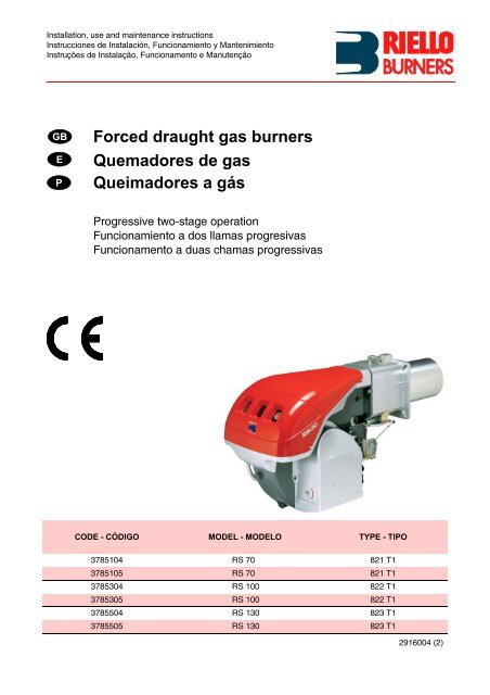
<strong>Forced</strong> <strong>draught</strong> <strong>gas</strong> <strong>burners</strong><br />
<strong>Quemadores</strong> <strong>de</strong> <strong>gas</strong><br />
Queimadores a gás<br />
Progressive two-stage operation<br />
Funcionamiento a dos llamas progresivas<br />
Funcionamento a duas chamas progressivas<br />
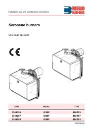
CODE - CÓDIGO MODEL - MODELO TYPE - TIPO<br />
3785104 RS 70 821 T1<br />
3785105 RS 70 821 T1<br />
3785304 RS 100 822 T1<br />
3785305 RS 100 822 T1<br />
3785504 RS 130 823 T1<br />
3785505 RS 130 823 T1<br />
2916004 (2)
GB<br />
CONTENTS<br />
TECHNICAL DATA . . . . . . . . . . . . . . . . . . . . . . . . . . . . . . page 2<br />
Variants . . . . . . . . . . . . . . . . . . . . . . . . . . . . . . . . . . . . . . . . . . . . 2<br />
Accessories . . . . . . . . . . . . . . . . . . . . . . . . . . . . . . . . . . . . . . . . . 2<br />
Burner <strong>de</strong>scription . . . . . . . . . . . . . . . . . . . . . . . . . . . . . . . . . . . . 3<br />
Packaging - Weight . . . . . . . . . . . . . . . . . . . . . . . . . . . . . . . . . . . 3<br />
Max. dimensions . . . . . . . . . . . . . . . . . . . . . . . . . . . . . . . . . . . . . 3<br />
Standard equipment . . . . . . . . . . . . . . . . . . . . . . . . . . . . . . . . . . . 3<br />
Firing rates . . . . . . . . . . . . . . . . . . . . . . . . . . . . . . . . . . . . . . . . . . 4<br />
Test boiler. . . . . . . . . . . . . . . . . . . . . . . . . . . . . . . . . . . . . . . . . . . 4<br />
Commercial boilers. . . . . . . . . . . . . . . . . . . . . . . . . . . . . . . . . . . . 4<br />
Gas pressure . . . . . . . . . . . . . . . . . . . . . . . . . . . . . . . . . . . . . . . . 5<br />
INSTALLATION . . . . . . . . . . . . . . . . . . . . . . . . . . . . . . . . . . . . . . 6<br />
Boiler plate . . . . . . . . . . . . . . . . . . . . . . . . . . . . . . . . . . . . . . . . . . 6<br />
Blast tube length . . . . . . . . . . . . . . . . . . . . . . . . . . . . . . . . . . . . . 6<br />
Securing the burner to the boiler . . . . . . . . . . . . . . . . . . . . . . . . . 6<br />
Setting the combustion head . . . . . . . . . . . . . . . . . . . . . . . . . . . . 7<br />
Gas line . . . . . . . . . . . . . . . . . . . . . . . . . . . . . . . . . . . . . . . . . . . . 8<br />
Electrical system . . . . . . . . . . . . . . . . . . . . . . . . . . . . . . . . . . . . . 9<br />
Adjustments before firing . . . . . . . . . . . . . . . . . . . . . . . . . . . . . . 12<br />
Servomotor. . . . . . . . . . . . . . . . . . . . . . . . . . . . . . . . . . . . . . . . . 12<br />
Burner starting . . . . . . . . . . . . . . . . . . . . . . . . . . . . . . . . . . . . . . 12<br />
Burner firing . . . . . . . . . . . . . . . . . . . . . . . . . . . . . . . . . . . . . . . . 12<br />
Burner calibration: . . . . . . . . . . . . . . . . . . . . . . . . . . . . . . . . . . . 13<br />
1 - Firing output . . . . . . . . . . . . . . . . . . . . . . . . . . . . . . . . . . . . . 13<br />
2 - 2nd stage output . . . . . . . . . . . . . . . . . . . . . . . . . . . . . . . . . . 13<br />
3 - 1st stage output. . . . . . . . . . . . . . . . . . . . . . . . . . . . . . . . . . . 14<br />
4 - Intermediates outputs . . . . . . . . . . . . . . . . . . . . . . . . . . . . . . 14<br />
5 - Air pressure switch . . . . . . . . . . . . . . . . . . . . . . . . . . . . . . . . 15<br />
6 - Minimum <strong>gas</strong> pressure switch. . . . . . . . . . . . . . . . . . . . . . . . 15<br />
Flame present check . . . . . . . . . . . . . . . . . . . . . . . . . . . . . . . . . 15<br />
Burner operation. . . . . . . . . . . . . . . . . . . . . . . . . . . . . . . . . . . . . 16<br />
Final checks . . . . . . . . . . . . . . . . . . . . . . . . . . . . . . . . . . . . . . . . 17<br />
Maintenance. . . . . . . . . . . . . . . . . . . . . . . . . . . . . . . . . . . . . . . . 17<br />
Burner start-up cycle diagnostics. . . . . . . . . . . . . . . . . . . . . . . 18<br />
Resetting the control box and using diagnostics. . . . . . . . . . . 18<br />
Fault - Probable cause - Suggested remedy . . . . . . . . . . . . . . . 19<br />
Status (optional) . . . . . . . . . . . . . . . . . . . . . . . . . . . . . . . . . . . . . 20<br />
N.B.<br />
Figures mentioned in the text are i<strong>de</strong>ntified as follows:<br />
1)(A) = part 1 of figure A, same page as text;<br />
1)(A)p.3 = part 1 of figure A, page number 3.<br />
1
TECHNICAL DATA<br />
10<br />
MODEL RS 70 RS 100 RS 130<br />
TYP 821 T1 822 T1 823 T1<br />
OUTPUT (1) 2nd stage kW 465 - 814<br />
698 - 1163<br />
930 - 1512<br />
Mcal/h 400 - 700<br />
600 - 1000<br />
800 - 1300<br />
min. 1st stage kW 192<br />
232<br />
372<br />
Mcal/h<br />
165<br />
200<br />
320<br />
FUEL<br />
NATURAL GAS: G20 - G21 - G22 - G23 - G25<br />
G20 G25 G20 G25 G20 G25<br />
- Net calorific value kWh/Nm 3<br />
8,6 10 8,6 10 8,6<br />
Mcal/Nm 3 8,6 7,4 8,6 7,4 8,6 7,4<br />
- Absolute <strong>de</strong>nsity kg/Nm 3 0,71 0,78 0,71 0,78 0,71 0,78<br />
- Max. <strong>de</strong>livery Nm 3 /h 81 94 116 135 151 175<br />
- Pressure at maximum <strong>de</strong>livery (2) mbar 10,3 15,2 9,3 13,7 8,6 12,7<br />
OPERATION<br />
• Intermittent (min. 1 stop in 24 hours).<br />
• Two-stage (high and low flame) and single-stage (all-nothing)<br />
STANDARD APPLICATIONS<br />
Boilers: water, steam, diathermic oil<br />
AMBIENT TEMPERATURE °C 0 - 40<br />
COMBUSTION AIR TEMPERATURE °C max 60<br />
ELECTRICAL SUPPLY<br />
V<br />
Hz<br />
230 - 400 with neutral ~ +/-10%<br />
50 - three-phase<br />
ELECTRIC MOTOR<br />
rpm<br />
W<br />
V<br />
A<br />
2800<br />
1100<br />
220/240 - 380/415<br />
4,8 - 2,8<br />
2800<br />
1500<br />
220/240 - 380/415<br />
5,9 - 3,4<br />
2800<br />
2200<br />
220/240 - 380/415<br />
8,8 - 5,1<br />
IGNITION TRANSFORMER<br />
V1 - V2<br />
I1 - I2<br />
230 V - 1 x 8 kV<br />
1 A - 20 mA<br />
ELECTRICAL POWER CONSUMPTION W max 1400 1800 2600<br />
ELECTRICAL PROTECTION IP 44<br />
IN CONFORMITY WITH EEC DIRECTIVES 90/396 - 89/336 - 73/23<br />
NOISE LEVELS (3) dBA 75 77 78,5<br />
APPROVAL CE 0085AP0944 0085AP0945 0085AP0946<br />
(1) Reference conditions: Ambient temperature 20°C - Barometric pressure 1000 mbar - Altitu<strong>de</strong> 100 m a.s.l.<br />
(2) Pressure at test point 16)(A)p.3, with zero pressure in the combustion chambre, with open <strong>gas</strong> ring 2)(B)p.7 an maximum burner output<br />
(3) Sound pressure measured in manufacturers combustion laboratory, with burner operating on test boiler and at maximum rated output.<br />
VARIANTS<br />
GAS CATEGORY<br />
Mo<strong>de</strong>l<br />
Electrical<br />
supply<br />
Blast tube<br />
length mm<br />
COUNTRY<br />
CATEGORY<br />
RS 70<br />
three-phase<br />
three-phase<br />
250<br />
385<br />
IT - AT - GR - DK - FI - SE<br />
ES - GB - IE - PT<br />
II 2H3B / P<br />
II 2H3P<br />
RS 100<br />
three-phase<br />
three-phase<br />
250<br />
385<br />
NL<br />
FR<br />
II 2L3B / P<br />
II 2Er3P<br />
RS 130<br />
three-phase<br />
three-phase<br />
280<br />
415<br />
DE<br />
BE<br />
II 2ELL3B /P<br />
I 2E(R)B, I 3P<br />
LU<br />
II 2E 3B/P<br />
ACCESSORIES (optional):<br />
• KIT FOR LPG OPERATION: The kit allows the RS 70-100-130 <strong>burners</strong> to operate on LPG.<br />
BURNER RS 70 RS 100 RS 130<br />
OUTPUT kW 242 … 814 349 … 1163 466 … 1512<br />
BLAST TUBE LENGTH mm 250 385 250 385 280 415<br />
CODE 3010097 3010098 3010099 3010100 3010101 3010102<br />
• VIBRATION REDUCTION KIT<br />
BURNER RS 70 RS 100 RS 130<br />
BLAST TUBE LENGTH mm 250 385 250 385 280 415<br />
CODE 3010201 3010202 3010373 3010374<br />
• STATUS (see page 20): co<strong>de</strong> 3010322<br />
• GAS TRAIN ACCORDING TO REGULATION EN 676 (with valves, pressure governor and filter): see page 8.<br />
Important:<br />
The installer is responsible for the addition of any safety <strong>de</strong>vice not forseen in the present manual.<br />
2
D3139<br />
D36<br />
mm A B C kg<br />
RS 70 1300 740 682 70<br />
RS 100 1300 740 682 73<br />
RS 130 1300 740 682 76<br />
(A)<br />
(B)<br />
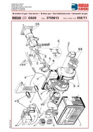
BURNER DESCRIPTION (A)<br />
1 Combustion head<br />
2 Ignition electro<strong>de</strong><br />
3 Screw for combustion head adjustment<br />
4 Sleeve<br />
5 Servomotor controlling the <strong>gas</strong> butterfly<br />
valve and of air gate valve (by means of a<br />
variable profile cam mechanism).<br />
When the burner is stopped the air gate<br />
valve will be completely closed to reduce<br />
heat loss due to the flue <strong>draught</strong>, which<br />
tends to draw air from the fan air inlet.<br />
6 Extension for sli<strong>de</strong> bars 15)<br />
7 Motor contactor and thermal cut-out reset<br />
button<br />
8 Plug-socket on ionisation probe cable<br />
9 Terminal strip<br />
10 Fairleads for electrical connections by installer<br />
11 Two switches:<br />
- one ≈burner off-on∆<br />
- one for ≈1st - 2nd stage operation∆<br />
12 Control box with lock-out pilot light and lockout<br />
reset button<br />
13 Flame inspection window<br />
14 Minimum air pressure switch<br />
(differential operating type)<br />
15 Sli<strong>de</strong> bars for opening the burner and<br />
inspecting the combustion head<br />
16 Gas pressure test point and head fixing screw<br />
17 Air pressure test point<br />
18 Flame sensor probe<br />
19 Air gate valve<br />
20 Air inlet to fan<br />
21 Screws securing fan to sleeve<br />
22 Gas input pipework<br />
23 Gas butterfly valve<br />
24 Boiler mounting flange<br />
25 Flame stability disk<br />
26 Socket for electrical connections<br />
Two types of burner failure may occur:<br />
• Control box lock-out: if the control box<br />
12)(A) pushbutton (red led) lights up, it indicates<br />
that the burner is in lock-out.<br />
To reset, hold the pushbutton down for<br />
between 1 and 3 seconds.<br />
• Motor trip: release by pressing the pushbutton<br />
on thermal cutout 7)(A).<br />
PACKAGING - WEIGHT (B)<br />
Approximate measurements<br />
• The burner stands on a woo<strong>de</strong>n base which<br />
can be lifted by fork-lifts.<br />
Outer dimensions of packaging are indicated<br />
in (B).<br />
• The weight of the burner complete with packaging<br />
is indicated in Table (B).<br />
D731<br />
mm A B C D E F (1) G H I (1) L M N O<br />
RS 70 511 296 215 555 840 250 - 385 179 430 1161-1296 214 134 221 2∆<br />
RS 100 527 312 215 555 840 250 - 385 179 430 1161-1296 214 134 221 2∆<br />
RS 130 553 338 215 555 840 280 - 415 189 430 1161-1296 214 134 221 2∆<br />
(1) Blast tube: short-lang<br />
(C)<br />
MAX. DIMENSIONS (C)<br />
Approximate measurements<br />
The maximum dimensions of the burner are<br />
given in (C).<br />
Bear in mind that inspection of the combustion<br />
head requires the burner to be opened by withdrawing<br />
the rear part on the sli<strong>de</strong> bars.<br />
The maximum dimension of the burner when<br />
open is give by measurement I.<br />
STANDARD EQUIPMENT<br />
1 - Gas train flange<br />
1 - Flange <strong>gas</strong>ket<br />
4 - Flange fixing screws M 10 x 35<br />
1 - Thermal insulation screen<br />
2 - Extensions 6)(A) for sli<strong>de</strong> bars 15)(A)<br />
(for mo<strong>de</strong>ls with 385-415 mm blast tube)<br />
4 - Screws to secure the burner flange to the<br />
boiler: M 12 x 35<br />
3 - Plugs for electrical connections<br />
1 - Instruction booklet<br />
1 - Spare parts list<br />
3
Combustion chamber<br />
RS 70<br />
RS 100<br />
RS 130<br />
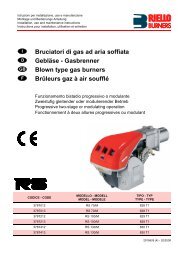
FIRING RATES (A)<br />
The RS 70-100-130 Mo<strong>de</strong>l <strong>burners</strong> can work in<br />
two ways: one-stage and two-stage<br />
MAXIMUM OUTPUT must be selected in area A.<br />
In or<strong>de</strong>r to utilize also area B (RS 130) it is necessary<br />
to perform the calibration of the combustion<br />
head as explained on page 6.<br />
MINIMUM OUTPUT must not be lower than the<br />
minimum limit shown in the diagram.<br />
RS 70 = 192 kW<br />
RS 100 = 232 kW<br />
RS 130 = 372 kW<br />
Important<br />
The FIRING RATE value range has been<br />
obtained consi<strong>de</strong>ring an ambient temperature of<br />
20 °C, and an atmospheric pressure of 1000<br />
mbar (approx. 100 m above sea level) and with<br />
the combustion head adjusted as shown on<br />
page 7.<br />
TEST BOILER (B)<br />
The firing rates were set in relation to special<br />
test boilers, according to EN 676 regulations.<br />
Figure (B) indicates the diameter and length of<br />
the test combustion chamber.<br />
Example:<br />
Output 756 kW:<br />
diameter = 60 cm; length = 2 m.<br />
COMMERCIAL BOILERS<br />
The burner/boiler combination does not pose<br />
any problems if the boiler is CE type-approved<br />
and its combustion chamber dimensions are<br />
similar to those indicated in diagram (B).<br />
If the burner must be combined with a commercial<br />
boiler that has not been CE type-approved<br />
and/or its combustion chamber dimensions are<br />
clearly smaller than those indicated in diagram<br />
(B), consult the manufacturer.<br />
(A)<br />
D950<br />
Combustion chamber<br />
length m<br />
Combustion chamber<br />
pressure mbar<br />
Combustion chamber<br />
pressure mbar<br />
pressure mbar<br />
(B)<br />
D715<br />
4
RS 70<br />
kW 1 2<br />
465<br />
515<br />
565<br />
615<br />
665<br />
715<br />
765<br />
814<br />
RS 100<br />
RS 130<br />
4,2<br />
4,8<br />
5,6<br />
6,4<br />
7,3<br />
8,3<br />
9,3<br />
10,3<br />
0,2<br />
0,2<br />
0,3<br />
0,3<br />
0,3<br />
0,4<br />
0,4<br />
0,4<br />
kW 1 2<br />
695<br />
760<br />
825<br />
890<br />
955<br />
1020<br />
1085<br />
1163<br />
3,7<br />
4,2<br />
5,0<br />
5,8<br />
6,5<br />
7,3<br />
8,3<br />
9,3<br />
0,4<br />
0,4<br />
0,5<br />
0,5<br />
0,6<br />
0,7<br />
0,8<br />
0,8<br />
kW 1 2<br />
930<br />
1010<br />
1090<br />
1170<br />
1250<br />
1330<br />
1410<br />
1512<br />
3,8<br />
4,5<br />
5,1<br />
5,8<br />
6,5<br />
7,2<br />
7,9<br />
8,6<br />
1,0<br />
1,1<br />
1,3<br />
1,5<br />
1,7<br />
1,8<br />
1,9<br />
2,0<br />
Æ 1∆ 1/2<br />
3970145<br />
11,6<br />
13,9<br />
16,3<br />
18,9<br />
21,7<br />
24,6<br />
27,7<br />
30,9<br />
Æ 1∆ 1/2<br />
3970145<br />
23,5<br />
27,4<br />
31,6<br />
36,1<br />
40,9<br />
45,9<br />
51,1<br />
57,7<br />
Æ 1∆ 1/2<br />
3970145<br />
39,0<br />
44,9<br />
51,5<br />
58,3<br />
65,4<br />
72,9<br />
80,7<br />
91,2<br />
Æ 1∆ 1/2<br />
3970180<br />
8,5<br />
10,0<br />
12,0<br />
13,5<br />
15,0<br />
17,2<br />
18,5<br />
20,0<br />
Æ 1∆ 1/2<br />
3970180<br />
17,0<br />
18,5<br />
20,5<br />
23,0<br />
26,0<br />
29,0<br />
33,0<br />
38,0<br />
Æ 1∆ 1/2<br />
3970180<br />
22,0<br />
28,0<br />
33,0<br />
37,0<br />
40,0<br />
43,0<br />
48,0<br />
53,0<br />
∆p (mbar)<br />
Æ 2∆<br />
3970146<br />
3970160<br />
4,8<br />
5,8<br />
6,8<br />
8,0<br />
9,2<br />
10,5<br />
11,3<br />
13,2<br />
∆p (mbar)<br />
Æ 2∆<br />
3970146<br />
3970160<br />
9,9<br />
11,7<br />
13,6<br />
15,6<br />
17,7<br />
19,9<br />
22,3<br />
25,3<br />
∆p (mbar)<br />
Æ 2∆<br />
3970146<br />
3970160<br />
16,9<br />
19,6<br />
22,5<br />
25,6<br />
28,8<br />
32,2<br />
35,8<br />
40,6<br />
3<br />
3<br />
3<br />
Æ 2∆<br />
3970181<br />
3970182<br />
5,2<br />
6,2<br />
7,2<br />
8,2<br />
9,5<br />
10,8<br />
11,5<br />
13,0<br />
Æ 2∆<br />
3970181<br />
3970182<br />
10,1<br />
11,5<br />
13,2<br />
14,0<br />
16,0<br />
18,0<br />
20,0<br />
22,0<br />
Æ 2∆<br />
3970181<br />
3970182<br />
15,0<br />
17,0<br />
20,0<br />
22,0<br />
25,0<br />
28,0<br />
31,0<br />
34,0<br />
DN 65<br />
3970147<br />
3970161<br />
-<br />
-<br />
-<br />
-<br />
-<br />
-<br />
4,4<br />
5,0<br />
DN 65<br />
3970147<br />
3970161<br />
-<br />
4,4<br />
5,1<br />
5,8<br />
6,6<br />
7,5<br />
8,4<br />
9,5<br />
DN 65<br />
3970147<br />
3970161<br />
6,3<br />
7,4<br />
8,5<br />
9,6<br />
10,8<br />
12,2<br />
13,6<br />
15,3<br />
DN80<br />
3970148<br />
3970162<br />
-<br />
-<br />
-<br />
-<br />
-<br />
-<br />
-<br />
-<br />
DN80<br />
3970148<br />
3970162<br />
-<br />
-<br />
-<br />
-<br />
-<br />
-<br />
4,5<br />
5,0<br />
DN80<br />
3970148<br />
3970162<br />
-<br />
-<br />
4,5<br />
5,1<br />
5,7<br />
6,4<br />
7,1<br />
8,0<br />
(A)<br />
GAS PRESSURE<br />
The adjacent tables show minimum pressure<br />
losses along the <strong>gas</strong> supply line <strong>de</strong>pending on<br />
the burner output in 2nd stage operation.<br />
Column 1<br />
Pressure loss at combustion head.<br />
Gas pressure measured at test point 1)(B), with:<br />
• Combustion chamber at 0 mbar<br />
• Burner operating in 2nd stage<br />
• Gas ring 2)(B)p. 7 adjusted as indicated in<br />
diagram (C)p. 7.<br />
Column 2<br />
Pressure loss at <strong>gas</strong> butterfly valve 2)(B) with<br />
maximum opening: 90°.<br />
Column 3<br />
Pressure loss of <strong>gas</strong> train 3)(B) inclu<strong>de</strong>s: adjustment<br />
valve VR, safety valve VS (both fully<br />
open), pressure governor R, filter F.<br />
The values shown in the various tables refer to:<br />
natural <strong>gas</strong> G20 PCI 10 kWh/Nm 3 (8.6 Mcal/Nm 3 ).<br />
With:<br />
natural <strong>gas</strong> G25 PCI 8.6 kWh/Nm 3 (7.4 Mcal/Nm 3 )<br />
multiply tabulated values by 1.3.<br />
Calculate the approximate 2nd stage output of<br />
the burner thus:<br />
- subtract the combustion chamber pressure<br />
from the <strong>gas</strong> pressure measured at test point<br />
1)(B).<br />
- Find the nearest pressure value to your result<br />
in column 1 of the table for the burner in question.<br />
- Read off the corresponding output on the left.<br />
Example - RS 100:<br />
• 2nd stage operation<br />
• Natural <strong>gas</strong> G20 PCI 10 kWh/Nm 3<br />
• Gas ring 2)(B)p. 7 adjusted as indicated in<br />
diagram (C)p. 7.<br />
• Gas pressure at test point 1)(B) = 8 mbar<br />
• Pressure in combustion chamber = 3 mbar<br />
8 - 3 = 5 mbar<br />
A 2nd stage output of 825 kW shown in Table<br />
RS 100 corresponds to 5 mbar pressure, column<br />
1.<br />
This value serves as a rough gui<strong>de</strong>, the effective<br />
<strong>de</strong>livery must be measured at the <strong>gas</strong> meter.<br />
To calculate the required <strong>gas</strong> pressure at test<br />
point 1)(B), set the output required from the<br />
burner in 2nd stage operation:<br />
- find the nearest output value in the table for<br />
the burner in question.<br />
- Read off the pressure at test point 1)(B) on<br />
the right in column 1.<br />
- Add this value to the estimated pressure in<br />
the combustion chamber.<br />
Example - RS 100:<br />
• Required burner output in 2nd stage operation:<br />
825 kW<br />
• Natural <strong>gas</strong> G20 PCI 10 kWh/Nm 3<br />
• Gas ring 2)(B)p.7 adjusted as diagram (C)p.7.<br />
• Gas pressure at burner output of 825 kW,<br />
taken from table RS 100, column 1 = 5 mbar<br />
• Pressure in combustion chamber = 3 mbar<br />
5 + 3 = 8 mbar<br />
pressure required at test point 1)(B).<br />
4 + 2 = 6 mbar<br />
pressure required at test point 1)(B).<br />
D963<br />
(B)<br />
5
INSTALLATION<br />
mm A B C<br />
RS 70 185 275 - 325 M 12<br />
RS 100 185 275 - 325 M 12<br />
RS 130 195 275 - 325 M 12<br />
D455<br />
(A)<br />
BOILER PLATE (A)<br />
Drill the combustion chamber locking plate as<br />
shown in (A). The position of the threa<strong>de</strong>d holes<br />
can be marked using the thermal screen supplied<br />
with the burner.<br />
BLAST TUBE LENGTH (B)<br />
The length of the blast tube must be selected<br />
according to the indications provi<strong>de</strong>d by the<br />
manufacturer of the boiler, and in any case it<br />
must be greater than the thickness of the boiler<br />
door complete with its fettling. The range of<br />
lengths available, L (mm), is as follows:<br />
Blast tube 12): RS 70 RS 100 RS 130<br />
• short 250 250 280<br />
• long 385 385 415<br />
For boilers with front flue passes 15) or flame<br />
inversion chambers, protective fettling in refractory<br />
material 13) must be inserted between the<br />
boiler fettling 14) and the blast tube 12).<br />
This protective fettling must not compromise the<br />
extraction of the blast tube.<br />
For boilers having a water-cooled front the<br />
refractory fettling 13)-14)(B) is not required<br />
unless it is expressly requested by the boiler<br />
manufacturer.<br />
PROBE<br />
ELECTRODE<br />
D3031<br />
(B)<br />
SECURING THE BURNER TO THE BOILER (B)<br />
Before securing the burner to the boiler, check<br />
through the blast tube opening to make sure<br />
that the flame sensor probe and the ignition<br />
electro<strong>de</strong> are correctly set in position, as shown<br />
in (C).<br />
Now <strong>de</strong>tach the combustion head from the<br />
burner, fig.(B):<br />
- loosen the 4 screws 3) and remove the cover 1)<br />
- Disengage the articulated coupling 7) from<br />
the graduated sector 8).<br />
- Remove the screws 2) from the sli<strong>de</strong> bars 5).<br />
- Remove the two screws 4) and pull the burner<br />
back on sli<strong>de</strong> bars 5) by about 100 mm.<br />
Disconnect the wires from the probe and the<br />
electro<strong>de</strong> and then pull the burner completely<br />
off the sli<strong>de</strong> bars.<br />
COMBUSTION HEAD CALIBRATION<br />
At this point check, for mo<strong>de</strong>l RS 130, whether<br />
the maximum <strong>de</strong>livery of the burner in 2nd stage<br />
operation is contained in area A or in area B of<br />
the firing rate. See page 8.<br />
If it is in area A then no operation is required.<br />
If, on the other hand, it is in area B:<br />
- unscrew the screws 1)(D) and disassemble<br />
the blast tube 2).<br />
- Move the fixing of the rod 3)(D) from position<br />
A to position B, thereby causing the shutter 4)<br />
to retract.<br />
- Now refit the blast tube 2)(D) and the screws 1).<br />
Once this operation has been carried out (if it was<br />
required), secure the flange 11)(B) to the boiler<br />
plate, interposing the thermal insulating screen<br />
9)(B) supplied with the burner. Use the 4 screws,<br />
also supplied with the unit, after first protecting<br />
the thread with an anti-locking product.<br />
The seal between burner and boiler must be airtight.<br />
If you noticed any irregularities in positions of<br />
the probe or ignition electro<strong>de</strong> during the check<br />
mentioned above, remove screw 1)(E), extract<br />
the internal part 2)(E) of the head and proceed<br />
to set up the two components correctly.<br />
Do not attempt to turn the probe. Leave it in the<br />
position shown in (C) since if it is located too<br />
close to the ignition electro<strong>de</strong> the control box<br />
amplifier may be damaged.<br />
D613<br />
D738<br />
(C)<br />
(D)<br />
D718<br />
(E)<br />
6
SETTING THE COMBUSTION HEAD<br />
Installation operations are now at the stage<br />
where the blast tube and sleeve are secured to<br />
the boiler as shown in fig. (A). It is now a very<br />
simple matter to set up the combustion head, as<br />
this <strong>de</strong>pends solely on the output <strong>de</strong>veloped by<br />
the burner in 2nd stage operation.<br />
It is therefore essential to establish this value<br />
before proceeding to set up the combustion<br />
head.<br />
There are two adjustments to make on the<br />
head:<br />
air and <strong>gas</strong> <strong>de</strong>liveries.<br />
In diagram (C) find the notch to use for adjusting<br />
the air and the <strong>gas</strong>, and then proceed as follows:<br />
Air adjustment (A)<br />
Turn screw 4)(A) until the notch i<strong>de</strong>ntified is<br />
aligned with the front surface 5)(A) of the flange.<br />
Gas adjustment (B)<br />
Loosen the 3 screws 1)(B) and turn ring 2) until<br />
the notch i<strong>de</strong>ntified is aligned with in<strong>de</strong>x 3).<br />
Tighten the 3 screws 1) fully down.<br />
Example RS 70:<br />
Burner output = 581 kW (500 Mcal/h).<br />
If we consult diagram (C) we find that for this<br />
output, air and <strong>gas</strong> must be adjusted using<br />
notch 3, as shown in figs.(A) and (B).<br />
Note<br />
Diagram (C) shows the i<strong>de</strong>al settings for the<br />
combustion head. If the <strong>gas</strong> mains pressure is<br />
too low to reach the 2nd stage operation pressure<br />
indicated on page 5, and if the ring 2)(B) is<br />
not fully open, it can be opened wi<strong>de</strong>r by 1 or 2<br />
notches.<br />
Continuing with the previous example, page 5<br />
indicates that for burner RS 70 with output of<br />
581 kW (500 Mcal/h) a pressure of approximately<br />
6 mbar is necessary at test point 6)(A). If<br />
this pressure cannot be reached, open the ring<br />
2)(B) to notch 4 or 5.<br />
Make sure that the combustion characteristics<br />
are satisfactory and free of pulsations.<br />
Once you have finished setting up the head, refit<br />
the burner to the sli<strong>de</strong> bars 3)(D) at approximately<br />
100 mm from the sleeve 4)(D) - burner<br />
positioned as shown in fig.(B)p.6 - insert the<br />
flame <strong>de</strong>tection probe cable and the ignition<br />
electro<strong>de</strong> cable and then sli<strong>de</strong> the burner up to<br />
the sleeve so that it is positioned as shown in<br />
fig.(D).<br />
Refit screws 2) on sli<strong>de</strong> bars 3).<br />
Secure the burner to the sleeve by tightening<br />
screw 1).<br />
Reconnect the articulation 7) to the graduated<br />
sector 6).<br />
Important<br />
When fitting the burner on the two sli<strong>de</strong> bars, it<br />
is advisable to gently draw out the high tension<br />
cable and flame <strong>de</strong>tection probe cable until they<br />
are slightly stretched.<br />
(A)<br />
Notches nr. (Air = Gas)<br />
D719<br />
(B)<br />
(C)<br />
Burner output in 2nd stage operation<br />
D720<br />
(D)<br />
D3032<br />
7
(A)<br />
(B)<br />
GAS BURNERS AND RELEVANT GAS TRAINS APPROVED ACCORDING TO EN 676<br />
(C)<br />
Gas train L Burner 13 14<br />
Æ C.T. Co<strong>de</strong> RS 70 RS 100 RS 130 Co<strong>de</strong> Co<strong>de</strong><br />
1∆1/2<br />
1∆1/2<br />
2∆<br />
2∆<br />
2∆<br />
2∆<br />
DN 65<br />
DN 65<br />
DN 80<br />
DN 80<br />
-<br />
-<br />
-<br />
♦<br />
-<br />
♦<br />
-<br />
♦<br />
−<br />
♦<br />
3970145<br />
3970180<br />
3970146<br />
3970160<br />
3970181<br />
3970182<br />
3970147<br />
3970161<br />
3970148<br />
3970162<br />
GAS TRAIN COMPONENTS<br />
Co<strong>de</strong><br />
Filter<br />
5<br />
•<br />
•<br />
•<br />
•<br />
•<br />
•<br />
•<br />
•<br />
-<br />
-<br />
•<br />
•<br />
•<br />
•<br />
•<br />
•<br />
•<br />
•<br />
-<br />
-<br />
Components<br />
Pressure governor<br />
6<br />
•<br />
•<br />
•<br />
•<br />
•<br />
•<br />
•<br />
•<br />
•<br />
•<br />
3010123<br />
3010123<br />
3010123<br />
-<br />
3010123<br />
-<br />
3010123<br />
-<br />
3010123<br />
-<br />
Solenoids<br />
8 - 9<br />
3970145 GF 515/1 FRS 515 DMV-DLE 512/11<br />
3970180 Multiblock MB DLE 415<br />
3970146<br />
3970160<br />
GF 520/1 FRS 520 DMV-DLE 520/11<br />
3970181<br />
3970182<br />
Multiblock MB DLE 420<br />
3970147<br />
3970161<br />
GF 40065/3 FRS 5065 DMV-DLE 5065/11<br />
3970148<br />
3970162<br />
GF 40080/3 FRS 5080 DMV-DLE 5080/11<br />
D722<br />
D953<br />
3000843<br />
3000843<br />
-<br />
-<br />
-<br />
-<br />
3000825<br />
3000825<br />
3000826<br />
3000826<br />
GAS LINE<br />
• The <strong>gas</strong> train must be connected to the <strong>gas</strong><br />
attachment 1)(A), using flange 2), <strong>gas</strong>ket 3)<br />
and screws 4) supplied with the burner.<br />
• The <strong>gas</strong> train can enter the burner from the<br />
right or left si<strong>de</strong>, <strong>de</strong>pending on which is the<br />
most convenient, see fig.(A).<br />
• Gas solenoids 8)-9)(B) must be as close as<br />
possible to the burner to ensure <strong>gas</strong> reaches<br />
the combustion head within the safety time<br />
range of 3 s.<br />
• Make sure that the pressure governor calibration<br />
range (colour of the spring) comprises the<br />
pressure required by the burner.<br />
GAS TRAIN (B)<br />
It is type-approved according to EN 676 Standards<br />
and is supplied separately from the burner<br />
with the co<strong>de</strong> indicated in Table (C).<br />
KEY (B)<br />
1 - Gas input pipe<br />
2 - Manual valve<br />
3 - Vibration damping joint<br />
4 - Pressure gauge with pushbutton cock<br />
5 - Filter<br />
6 - Pressure governor (vertical)<br />
7 - Minimum <strong>gas</strong> pressure switch<br />
8 - Safety solenoid VS (vertical)<br />
9 - Adjustment solenoid VR (vertical)<br />
Two adjustments:<br />
• ignition <strong>de</strong>livery (rapid opening)<br />
• maximum <strong>de</strong>livery (slow opening)<br />
10 - Standard issue burner <strong>gas</strong>ket with flange<br />
11 - Gas adjustment butterfly valve<br />
12 - Burner<br />
13 - Gas valve 8)-9) leak <strong>de</strong>tection control<br />
<strong>de</strong>vice.<br />
In accordance with EN 676 Standards, <strong>gas</strong><br />
valve leak <strong>de</strong>tection control <strong>de</strong>vices are<br />
compulsory for <strong>burners</strong> with maximum outputs<br />
of more than 1200 kW; therefore only<br />
for mo<strong>de</strong>l RS 130.<br />
14 - Gas train/burner adaptor.<br />
P1 - Pressure at combustion head<br />
P2 - Pressure down-line from the pressure governor<br />
P3 - Pressure up-line from the filter<br />
L - Gas train supplied separately with the co<strong>de</strong><br />
indicated in Table (C)<br />
L1 - The responsibility of the installer<br />
KEY TO TABLE (C)<br />
C.T.=Gas valves 8) - 9) leak <strong>de</strong>tection control<br />
<strong>de</strong>vices:<br />
- = Gas train without <strong>gas</strong> valve leak <strong>de</strong>tection<br />
control <strong>de</strong>vice; <strong>de</strong>vice that can be<br />
or<strong>de</strong>red separately and assembled subsequently<br />
(see Column 13).<br />
♦= Gas train with assembled VPS valve<br />
leak <strong>de</strong>tection control <strong>de</strong>vice.<br />
13 =VPS valve leak <strong>de</strong>tection control <strong>de</strong>vice.<br />
Supplied separately from <strong>gas</strong> train on<br />
request.<br />
14 =Gas train/burner adaptor.<br />
Supplied separately from <strong>gas</strong> train on<br />
request.<br />
Note<br />
See the accompanying instructions for the<br />
adjustment of the <strong>gas</strong> train.<br />
8
ELECTRICAL EQUIPMENT FACTORY-SET<br />
RS 70 - RS 100 - RS 130<br />
ELECTRICAL SYSTEM<br />
ELECTRICAL SYSTEM as set up by the manufacturer<br />
(A)<br />
D3140<br />
LAYOUT (A)<br />
<strong>Burners</strong> RS 70 - RS 100 - RS 130<br />
• Mo<strong>de</strong>ls RS 70 - RS 100 - RS 130 leave the<br />
factory preset for 400 V power supply.<br />
• If 230 V power supply is used, change the<br />
motor connection from star to <strong>de</strong>lta and<br />
change the setting of the thermal cut-out as<br />
well.<br />
Key to Layout (A)<br />
CMV - Motor contactor<br />
DA - Control box (Landis RMG)<br />
F1 - Protection against radio interference<br />
K1 - Relay<br />
I1 - Switch: burner off - on<br />
I2 - Switch: 1st - 2nd stage operation<br />
MB - Burner terminal strip<br />
MV - Fan motor<br />
PA - Air pressure switch<br />
RT - Thermal cut-out<br />
SM - Servomotor<br />
SO - Ionisation probe<br />
SP - Plug-socket<br />
TA - Ignition transformer<br />
TB - Burner ground<br />
XP4 - 4 pole socket<br />
XP6 - 6 pole socket<br />
XP7 - 7 pole socket<br />
XP1 - Connector for STATUS<br />
ATTENTION<br />
In the case of phase-phase feed, a bridge<br />
must be fitted on the control box terminal strip<br />
between terminal 6 and the earth terminal.<br />
9
(A)<br />
RS 70 - RS 100 - RS 130 without leak <strong>de</strong>tection control <strong>de</strong>vice<br />
(B)<br />
RS 70 - RS 100 - RS 130 with leak <strong>de</strong>tection control <strong>de</strong>vice VPS<br />
(C)<br />
RS 70 RS 100 RS 130<br />
230 V 400 V 230 V 400 V 230 V 400 V<br />
F A T10 T6 T16 T10 T16 T10<br />
L mm 2 1,5 1,5 1,5 1,5 1,5 1,5<br />
D955<br />
D3141<br />
D3142<br />
ELECTRICAL CONNECTIONS<br />
Use flexible cables according to EN 60 335-1<br />
Regulations:<br />
• if in PVC sheath, use at least H05 VV-F<br />
• if in rubber sheath, use at least H05 RR-F.<br />
All the wires to connect to the burner terminal<br />
strip 9)(A) must enter through the supplied fairleads.<br />
The fairleads and hole press-outs can be used<br />
in various ways; the following lists show one<br />
possible solution:<br />
1 - Pg 13,5 Three-phase power supply<br />
2 - Pg 11 Socket XP6 - <strong>gas</strong> valves<br />
3 - Pg 11 Socket XP7 - remote control <strong>de</strong>vice<br />
TL and single-phase power supply<br />
4 - Pg 9 Socket XP4 - remote control <strong>de</strong>vice<br />
TR<br />
5 - Pg 13,5 Not utilized<br />
6 - Pg 13,5 Gas pressure switch or <strong>gas</strong> valve<br />
leak <strong>de</strong>tection control <strong>de</strong>vice<br />
7 - Pg 11 Open the hole, if a pipe union is to<br />
be ad<strong>de</strong>d<br />
8 - Pg 9 Open the hole, if a pipe union is to<br />
be ad<strong>de</strong>d<br />
LAYOUT (B)<br />
Electrical connection RS 70 - 100 - 130<br />
<strong>burners</strong> without leak <strong>de</strong>tection control<br />
<strong>de</strong>vice.<br />
LAYOUT (C)<br />
Electrical connection RS 70 - 100 - 130<br />
<strong>burners</strong> with VPS leak <strong>de</strong>tection control<br />
<strong>de</strong>vice.<br />
Gas valve leak <strong>de</strong>tection control takes place<br />
immediately before every burner start-up.<br />
Fuses and cables cross-section layouts (B) and<br />
(C), see table (D).<br />
Cross-section when not indicated: 1,5 mm 2 .<br />
KEY TO LAYOUTS (B - C)<br />
h1 - 1st stage hourcounter<br />
h2 - 2nd stage hourcounter<br />
IN - Burner manual stop switch<br />
X4 - 4 pole plug<br />
X6 - 6 pole plug<br />
X7 - 7 pole plug<br />
XP- Plug for leak <strong>de</strong>tection control <strong>de</strong>vice<br />
MB- Burner terminal strip<br />
PG- Min. <strong>gas</strong> pressure switch<br />
S - Remote lock-out signal<br />
S1 - Remote lock-out signal of leak <strong>de</strong>tection<br />
control <strong>de</strong>vice<br />
TR- High-low mo<strong>de</strong> load remote control system:<br />
controls operating stages 1 and 2.<br />
If the burner is to be set up for single stage<br />
operation, replace of remote control <strong>de</strong>vice<br />
TR with a jumper.<br />
TL - Load limit remote control system:<br />
shuts down the burner when the boiler temperature<br />
or pressure reaches the preset<br />
value.<br />
TS - Safety load control system:<br />
operates when TL is faulty<br />
VR- Adjustment valve<br />
VS- Safety valve<br />
(D)<br />
10
CALIBRATION OF THERMAL RELAY<br />
(A)<br />
D867<br />
LAYOUT (A)<br />
Calibration of thermal cut-out 7)(A)p. 3<br />
This is required to avoid motor burn-out in the<br />
event of a significant increase in power absorption<br />
caused by a missing phase.<br />
• If the motor is star-powered, 400 V, the cursor<br />
should be positioned to "MIN".<br />
• If the motor is <strong>de</strong>lta-powered, 230 V, the cursor<br />
should be positioned to "MAX".<br />
Even if the scale of the thermal cut-out does not<br />
inclu<strong>de</strong> rated motor absorption at 400 V, protection<br />
is still ensured in any case.<br />
N.B.<br />
• The RS 70-100-130 <strong>burners</strong> leave the factory<br />
preset for 400 V power supply. If 230 V power<br />
supply is used, change the motor connection<br />
from star to <strong>de</strong>lta and change the setting of<br />
the thermal cut-out as well.<br />
• The RS 70-100-130 <strong>burners</strong> have been typeapproved<br />
for intermittent operation. This<br />
means they should compulsorily be stopped<br />
at least once every 24 hours to enable the<br />
control box to check its own efficiency at startup.<br />
Burner halts are normally provi<strong>de</strong>d for<br />
automatically by the boiler load control system.<br />
If this is not the case, a time switch should be<br />
fitted in series to IN to provi<strong>de</strong> for burner shutdown<br />
at least once every 24 hours.<br />
• The RS 70-100-130 <strong>burners</strong> are factory set<br />
for two-stage operation and must therefore be<br />
connected to control <strong>de</strong>vice TR.<br />
Alternatively, if single stage operation is<br />
required, instead of control <strong>de</strong>vice TR install a<br />
jumper lead between terminals 6 and 7 of the<br />
terminal strip.<br />
WARNING: Do not invert the neutral with<br />
the phase wire in the electricity supply<br />
line. Inverting the wires will make the<br />
burner go into lock-out because of firing<br />
failure.<br />
11
MIN GAS PRESSURE SWITCH<br />
(A)<br />
AIR PRESSURE SWITCH<br />
(B)<br />
D897<br />
ADJUSTMENTS BEFORE FIRST FIRING<br />
Adjustment of the combustion head, and air and<br />
<strong>gas</strong> <strong>de</strong>liveries has been illustrated on page 7.<br />
In addition, the following adjustments must also<br />
be ma<strong>de</strong>:<br />
- open manual valves up-line from the <strong>gas</strong><br />
train.<br />
- Adjust the minimum <strong>gas</strong> pressure switch to<br />
the start of the scale (A).<br />
- Adjust the air pressure switch to the zero<br />
position of the scale (B).<br />
- Purge the air from the <strong>gas</strong> line.<br />
Continue to purge the air (we recommend<br />
using a plastic tube routed outsi<strong>de</strong> the building)<br />
until <strong>gas</strong> is smelt.<br />
- Fit a U-type manometer (C) to the <strong>gas</strong> pressure<br />
test point on the sleeve.<br />
The manometer readings are used to calculate<br />
the 2nd stage operation burner power<br />
using the tables on page 5.<br />
- Connect two lamps or testers to the two <strong>gas</strong><br />
line solenoid valves VR and VS to check the<br />
exact moment at which voltage is supplied.<br />
This operation is unnecessary if each of the<br />
two solenoid valves is equipped with a pilot<br />
light that signals voltage passing through.<br />
Before starting up the burner it is good practice<br />
to adjust the <strong>gas</strong> train so that ignition takes<br />
place in conditions of maximum safety, i.e. with<br />
<strong>gas</strong> <strong>de</strong>livery at the minimum.<br />
(C)<br />
SERVOMOTOR<br />
BLACK LEVER<br />
RED LEVER<br />
ORANGE LEVER<br />
D3033<br />
SERVOMOTOR (D)<br />
The servomotor provi<strong>de</strong>s simultaneous adjustment<br />
of the air gate valve, by means of the variable<br />
profile cam, and the <strong>gas</strong> butterfly valve.<br />
The angle of rotation of the servomotor is equal<br />
to the angle on the graduated sector controlling<br />
the <strong>gas</strong> butterfly valve. The servomotor rotates<br />
through 90 <strong>de</strong>grees in 15 seconds.<br />
Do not alter the factory setting for the 4 levers;<br />
simply check that they are set as indicated<br />
below:<br />
RED LEVER : 90°<br />
Limits rotation toward maximum position. When<br />
the burner is in 2nd stage operation the <strong>gas</strong> butterfly<br />
valve must be fully open: 90°.<br />
BLUE LEVER : 0°<br />
Limits rotation toward the minimum position.<br />
When the burner is shut down the air gate valve<br />
and the <strong>gas</strong> butterfly valve must be closed: 0°.<br />
ORANGE LEVER : 15°<br />
Adjusts the ignition position and the output in 1st<br />
stage operation.<br />
BLACK LEVER : 85°<br />
Lights up the 2nd stage LED (STATUS).<br />
A graduated plate with 4 coloured sectors marks<br />
the lever operation point.<br />
(D)<br />
BLUE LEVER<br />
1 2<br />
D728<br />
BURNER STARTING<br />
Close the control <strong>de</strong>vices and set:<br />
• switch 1)(E) to "Burner ON" position;<br />
• switch 2)(E) to "1st STAGE" position.<br />
As soon as the burner starts check the direction<br />
of rotation of the fan bla<strong>de</strong>, looking through the<br />
flame inspection window 13)(A)p.3.<br />
Make sure that the lamps or testers connected<br />
to the solenoids, or pilot lights on the solenoids<br />
themselves, indicate that no voltage is present.<br />
If voltage is present, then immediately stop the<br />
burner and check electrical connections.<br />
(E)<br />
Burner off<br />
Burner on<br />
1st stage<br />
2nd stage<br />
D469<br />
BURNER FIRING<br />
Having completed the checks indicated in the<br />
previous heading, the burner should fire. If the<br />
motor starts but the flame does not appear and<br />
the control box goes into lock-out, reset and wait<br />
for a new firing attempt.<br />
If firing is still not achieved, it may be that <strong>gas</strong> is<br />
not reaching the combustion head within the<br />
safety time period of 3 seconds.<br />
In this case increase <strong>gas</strong> firing <strong>de</strong>livery.<br />
The arrival of <strong>gas</strong> at the sleeve is indicated by<br />
the U-type manometer (C).<br />
Once the burner has fired, now proceed with<br />
global calibration operations.<br />
12
BURNER CALIBRATION<br />
The optimum calibration of the burner requires<br />
an analysis of the flue <strong>gas</strong>es at the boiler outlet.<br />
Adjust successively:<br />
1 - First firing output<br />
2 - 2nd stage burner output<br />
3 - 1st stage burner output<br />
4 - Intermediate outputs between 1st and 2nd stage<br />
5 - Air pressure switch<br />
6 - Minimum <strong>gas</strong> pressure switch<br />
Burner off<br />
Burner on<br />
1 2<br />
1st stage<br />
2nd stage<br />
(A)<br />
D469<br />
1 - FIRING OUTPUT<br />
According to EN 676 Regulations:<br />
<strong>Burners</strong> with max. output up to 120 kW<br />
Firing can be performed at the maximum operation<br />
output level. Example:<br />
• Max. operation output : 120 kW<br />
• Max. firing output : 120 kW<br />
<strong>Burners</strong> with max. output above 120 kW<br />
Firing must be performed at a lower output than<br />
the max. operation output. If the firing output<br />
does not exceed 120 kW, no calculations are<br />
required. If firing output exceeds 120 kW, the<br />
regulations prescribe that the value be <strong>de</strong>fined<br />
according to the control box safety time "ts":<br />
• for "ts" = 2s, firing output must be equal to or<br />
lower than 1/2 of max. operation output.<br />
• For "ts" = 3s, firing output must be equal to or<br />
lower than 1/3 of max. operation output.<br />
Example: MAX operation output of 600 kW.<br />
Firing output must be equal to or lower than:<br />
• 300 kW with "ts" = 2s<br />
• 200 kW with "ts" = 3s<br />
In or<strong>de</strong>r to measure the firing output:<br />
- disconnect the plug-socket 8)(A)p.3 on the<br />
ionization probe cable (the burner will fire and<br />
then go into lock-out after the safety time has<br />
elapsed).<br />
- Perform 10 firings with consecutive lock-outs.<br />
- On the meter read the quantity of <strong>gas</strong> burned.<br />
This quantity must be equal to or lower than<br />
the quantity given by the formula, for ts = 3s:<br />
Nm 3 /h (max. burner <strong>de</strong>livery)<br />
360<br />
Example: for G 20 <strong>gas</strong> (10 kWh/Nm 3 ):<br />
Max. operation output: 600 kW corresponding to<br />
60 Nm 3 /h.<br />
After 10 firings with lock-outs, the <strong>de</strong>livery read<br />
on the meter must be equal to or lower than:<br />
60 : 360 = 0,166 Nm 3 .<br />
2 - 2ND STAGE OUTPUT<br />
2nd stage output of the burner must be set<br />
within the firing rate range shown on page 4.<br />
In the above instructions we left the burner running<br />
in 1st stage operation. Now set switch 2)(A)<br />
to the 2nd stage position: the servomotor will<br />
open, simultaneously, the air gate valve and the<br />
<strong>gas</strong> butterfly valve to 90°.<br />
Gas calibration<br />
Measure the <strong>gas</strong> <strong>de</strong>livery at the meter.<br />
A gui<strong>de</strong>line indication can be calculated from the<br />
tables on page 5, simply read off the <strong>gas</strong> pressure<br />
on the U-type manometer, see fig.(C) on<br />
page 12, and follow the instructions on page 5.<br />
- If <strong>de</strong>livery needs to be reduced, diminish outlet<br />
<strong>gas</strong> pressure and, if it is already very low,<br />
slightly close adjustment valve VR.<br />
- If <strong>de</strong>livery needs to be increased, increase<br />
outlet <strong>gas</strong> pressure.<br />
13
Adjusting air <strong>de</strong>livery<br />
Progressively adjust the end profile of cam 3)(A)<br />
by turning the screws 5).<br />
- Turn the screws clockwise to increase air<br />
<strong>de</strong>livery.<br />
- Turn the screws counter-clockwise to reduce<br />
air <strong>de</strong>livery.<br />
D729<br />
1 Servomotor<br />
2 Cam cover<br />
3 Adjustable profile cam<br />
4 Cam starting profile adjustment screws<br />
5 Cam end profile adjustment screws<br />
6 Graduated sector for <strong>gas</strong> butterfly valve<br />
7 In<strong>de</strong>x for graduated sector 6<br />
BLACK LEVER<br />
RED LEVER<br />
ORANGE LEVER<br />
BLUE LEVER<br />
(A)<br />
(B)<br />
3 - 1ST STAGE OUTPUT<br />
Burner power in 1st stage operation must be<br />
selected within the firing rate range shown on<br />
page 4.<br />
Set the switch 2)(A)p.13 to the 1st stage position:<br />
the servomotor 1)(A) will close the air gate<br />
valve and, at the same time, closes the <strong>gas</strong> butterfly<br />
valve down to 15°, i.e. down to the original<br />
factory setting.<br />
Adjusting <strong>gas</strong> <strong>de</strong>livery<br />
Measure the <strong>de</strong>livery of <strong>gas</strong> from the <strong>gas</strong> meter.<br />
- If this value is to be reduced, <strong>de</strong>crease the<br />
angle of the orange lever (B) slightly by proceeding<br />
a little at a time until the angle is<br />
changed from 15° to 13° or 11°....<br />
- If it is necessary to increase the mains pressure,<br />
move to 2nd stage operation by altering<br />
the setting of switch 2)(A)p.13 and increase<br />
the angle of the orange lever, proceeding a little<br />
at a time until the angle is changed from<br />
15° to 17° - 19°....<br />
At this point return to 1st stage operation and<br />
measure <strong>gas</strong> <strong>de</strong>livery.<br />
Note<br />
The servomotor follows the adjustment of the<br />
orange lever only when the angle is reduced.<br />
If, however the angle must be increased, switch<br />
to 2nd stage operation, increase the angle and<br />
then return to 1st stage operation to check the<br />
effect of the adjustment.<br />
Adjustment of air <strong>de</strong>livery<br />
Progressively adjust the starting profile of cam<br />
3)(A) by turning the screws 4). It is preferable<br />
not to turn the first screw since this is used to set<br />
the air gate valve to its fully-closed position.<br />
4 - INTERMEDIATE OUTPUTS<br />
Adjustment of <strong>gas</strong> <strong>de</strong>livery<br />
No adjustment of <strong>gas</strong> <strong>de</strong>livery is required.<br />
Adjustment of air <strong>de</strong>livery<br />
Switch off the burner using switch 1)(A)p.13 and<br />
turn the central screws of the cam so that the<br />
cam offers a progressive gradient.<br />
Do not alter the position of the screws at each<br />
end of the cam track, which have already been<br />
adjusted for 1st and 2nd stage air gate valve<br />
control.<br />
Note<br />
Once you have finished adjusting outputs 2ND<br />
STAGE - 1ST STAGE - INTERMEDIATE, check<br />
ignition once again: noise emission at this stage<br />
must be i<strong>de</strong>ntical to the following stage of operation.<br />
If you notice any sign of pulsations, reduce the<br />
ignition stage <strong>de</strong>livery.<br />
14
AIR PRESSURE SWITCH 14)(A)p. 3<br />
(A)<br />
MIN GAS PRESSURE SWITCH 7)(B)p. 8<br />
(B)<br />
(C)<br />
D521<br />
D896<br />
D3023<br />
5 - AIR PRESSURE SWITCH (A)<br />
Adjust the air pressure switch after having performed<br />
all other burner adjustments with the air<br />
pressure switch set to the start of the scale (A).<br />
With the burner operating in 1st stage, increase<br />
adjustment pressure by slowly turning the relative<br />
knob clockwise until the burner locks out.<br />
Then turn the knob anti-clockwise by about 20%<br />
of the set point and repeat burner starting to<br />
ensure it is correct.<br />
If the burner locks out again, turn the knob anticlockwise<br />
a little bit more.<br />
Attention<br />
As a rule, the air pressure switch must limit the<br />
CO in the fumes to less than 1% (10,000 ppm).<br />
To check this, insert a combustion analyser into<br />
the chimney, slowly close the fan suction inlet<br />
(for example with cardboard) and check that the<br />
burner locks out, before the CO in the fumes<br />
exceeds 1%.<br />
The air pressure switch may operate in "differential"<br />
operation in two pipe system. If a negative<br />
pressure in the combustion chamber during<br />
pre-purging prevents the air pressure switch<br />
from switching, switching may be obtained by fitting<br />
a second pipe between the air pressure<br />
switch and the suction inlet of the fan. In such a<br />
manner the air pressure switch operates as differenzial<br />
pressure switch.<br />
Warning<br />
The use of the air pressure switch with differential<br />
operation is allowed only in industrial applications<br />
and where rules enable the air pressure<br />
switch to control only fan operation without any<br />
reference to CO limit.<br />
6 - MINIMUM GAS PRESSURE SWITCH (B)<br />
Adjust the minimum <strong>gas</strong> pressure switch after<br />
having performed all the other burner adjustments<br />
with the pressure switch set at the start of<br />
the scale (B).<br />
With the burner operating in 2nd stage, increase<br />
adjustment pressure by slowly turning the relative<br />
knob clockwise until the burner locks out.<br />
Then turn the knob anti-clockwise by 2 mbar<br />
and repeat burner starting to ensure it is uniform.<br />
If the burner locks out again, turn the knob anticlockwise<br />
again by 1 mbar.<br />
FLAME PRESENT CHECK (C)<br />
The burner is fitted with an ionisation system<br />
which ensures that a flame is present. The minimum<br />
current for plant operation is 5 ±A.<br />
The burner provi<strong>de</strong>s a much higher current, so<br />
that controls are not normally required. However,<br />
if it is necessary to measure the ionisation<br />
current, disconnect the plug-socket 8)(A)p.3 on<br />
the ionisation probe cable and insert a direct<br />
current microamperometer with a base scale of<br />
100 ±A.<br />
Carefully check polarities!<br />
15
RMG<br />
LED *<br />
(A)<br />
(B)<br />
*<br />
RMG<br />
LED *<br />
*<br />
NORMAL FIRING<br />
(n° = seconds from instant 0)<br />
Off Yellow Green Red<br />
For further <strong>de</strong>tails see page 18.<br />
NO FIRING<br />
Off Yellow Red<br />
For further <strong>de</strong>tails see page 18.<br />
D3051<br />
D3052<br />
BURNER OPERATION<br />
BURNER STARTING (A)<br />
• : Control <strong>de</strong>vice TL closes.<br />
Servomotor starts: it rotates during<br />
opening up to the angle set on cam<br />
with orange lever.<br />
After about 3s:<br />
• 0 s : The control box starting cycle begins.<br />
• 2 s : Fan motor starts.<br />
• 3 s : Servomotor starts: it rotates during<br />
opening until contact is ma<strong>de</strong> on cam<br />
with red lever.<br />
The air gate valve is positioned to 2nd<br />
stage output.<br />
Pre-purge stage with air <strong>de</strong>livery at<br />
2nd stage output.<br />
Duration 25 seconds.<br />
• 28 s : Servomotor starts: it rotates during<br />
closing up to the angle set on cam<br />
with orange lever.<br />
• 43 s : The air gate valve and the <strong>gas</strong> butterfly<br />
are positioned to 1st stage output.<br />
Ignition electro<strong>de</strong> strikes a spark.<br />
Safety valve VS and adjustment valve<br />
VR (rapid opening) open. The flame<br />
is ignited at a low output level, point<br />
A. Output is then progressively<br />
increased, with the valve opening<br />
slowly up to 1st stage output, point B.<br />
• 45 s : The spark goes out.<br />
• 53 s : If remote control <strong>de</strong>vice TR is closed<br />
or if it has been replaced by a jumper,<br />
the servomotor will continue to turn<br />
until the cam with red lever come into<br />
operation, setting the air gate valve<br />
and the <strong>gas</strong> butterfly valve to the 2nd<br />
stage operation position, section C-D.<br />
The control box starting cycle ends.<br />
STEADY STATE OPERATION (A)<br />
System equipped with one control <strong>de</strong>vice TR.<br />
Once the starting cycle has come to an end,<br />
control of the servomotor passes on to the control<br />
<strong>de</strong>vice TR that controls boiler temperature or<br />
pressure, point D.<br />
(The control box will continue, however, to monitor<br />
flame presence and the correct position of<br />
the air pressure switch).<br />
• When the temperature or the pressure<br />
increases until the control <strong>de</strong>vice TR opens,<br />
the servomotor closes the <strong>gas</strong> butterfly valve<br />
and the air gate valve and the burner passes<br />
from the 2nd to the 1st stage of operation,<br />
section E-F.<br />
• When the temperature or pressure <strong>de</strong>creases<br />
until the control <strong>de</strong>vice TR closes, the servomotor<br />
opens the <strong>gas</strong> butterfly valve and the<br />
air gate valve and the burner passes from the<br />
1st to the 2nd stage of operation, and so on.<br />
• The burner stops when the <strong>de</strong>mand for heat<br />
is less than the amount of heat <strong>de</strong>livered by<br />
the burner in the 1st stage, section G-H. Control<br />
<strong>de</strong>vice TL now opens, the servomotor<br />
returns toward the 0° position, limited in this<br />
movement by cam with blue lever. The air<br />
gate valve closes completely to reduce heat<br />
losses to a minimum.<br />
Systems not equipped with control <strong>de</strong>vice TR<br />
(jumper wire installed)<br />
The burner is fired as <strong>de</strong>scribed in the case<br />
above. If the temperature or pressure increase<br />
until control <strong>de</strong>vice TL opens, the burner shuts<br />
down (Section A-A in the diagram).<br />
FIRING FAILURE (B)<br />
If the burner does not fire, it goes into lock-out<br />
within 3 s of the opening of the <strong>gas</strong> solenoid<br />
valve and 49 s after the closing of control<br />
<strong>de</strong>vice TL. The control box red pilot light will<br />
light up.<br />
BURNER FLAME GOES OUT DURING OPER-<br />
ATION<br />
If the flame should acci<strong>de</strong>ntally go out during<br />
operation, the burner will lock out within 1s.<br />
16
FLAME INSPECTION WINDOW<br />
(A)<br />
OPENING THE BURNER<br />
(B)<br />
D709<br />
D3034<br />
FINAL CHECKS (with burner running)<br />
• Disconnect one of the wires on the minimum<br />
<strong>gas</strong> pressure switch:<br />
• Open remote control <strong>de</strong>vice TL:<br />
• Open remote control <strong>de</strong>vice TS:<br />
the burner must stop<br />
• Disconnect the common wire P from the air<br />
pressure switch:<br />
• Disconnect the ionisation probe lead:<br />
the burner must lock out<br />
• Make sure that the mechanical locking systems<br />
on the various adjustment <strong>de</strong>vices are<br />
fully tightened.<br />
MAINTENANCE<br />
Combustion<br />
The optimum calibration of the burner requires<br />
an analysis of the flue <strong>gas</strong>es. Significant differences<br />
with respect to the previous measurements<br />
indicate the points where more care<br />
should be exercised during maintenance.<br />
Gas leaks<br />
Make sure that there are no <strong>gas</strong> leaks on the<br />
pipework between the <strong>gas</strong> meter and the burner.<br />
Gas filter<br />
Change the <strong>gas</strong> filter when it is dirty.<br />
Flame inspection window<br />
Clean the flame inspection window (A).<br />
Combustion head<br />
Open the burner and make sure that all components<br />
of the combustion head are in good condition,<br />
not <strong>de</strong>formed by the high temperatures,<br />
free of impurities from the surroundings and correctly<br />
positioned. If in doubt, disassemble the<br />
elbow fitting 5)(B).<br />
Burner<br />
Check for excess wear or loose screws in the<br />
mechanisms controlling the air gate valve and<br />
the <strong>gas</strong> butterfly valve. Also make sure that the<br />
screws securing the electrical leads in the<br />
burner terminal strip are fully tightened.<br />
Clean the outsi<strong>de</strong> of the burner, taking special<br />
care with the transmission joints and cam<br />
3)(A)p.14.<br />
Combustion<br />
Adjust the burner if the combustion values found<br />
at the beginning of the operation do not comply<br />
with the regulations in force, or at any rate, do<br />
not correspond to good combustion. Use the<br />
appropriate card to record the new combustion<br />
values; they will be useful for subsequent controls.<br />
TO OPEN THE BURNER (B):<br />
- switch off the electrical power.<br />
- Loosen screws 1) and withdraw cover 2).<br />
- Disengage the articulated coupling 7) from<br />
the graduated sector 8).<br />
- Fit the two standard supplied extensions onto<br />
the sli<strong>de</strong> bars 4) (mo<strong>de</strong>ls with 385-415 mm<br />
blast tube).<br />
- Remove screws 3), and pull the burner back<br />
by about 100 mm on the sli<strong>de</strong> bars 4). Disconnect<br />
the probe and electro<strong>de</strong> leads and then<br />
pull the burner fully back.<br />
Now extract the <strong>gas</strong> distributor 5) after having<br />
removed the screw 6).<br />
TO CLOSE THE BURNER (B):<br />
- push the burner until it is about 100 mm from<br />
the sleeve.<br />
- Re-connect the leads and sli<strong>de</strong> in the burner<br />
until it comes to a stop.<br />
- Refit screws 3), and pull the probe and electro<strong>de</strong><br />
leads gently out until they are slightly<br />
stretched.<br />
- Re-couple the articulated coupling 7) to the<br />
graduated sector 8).<br />
- Remove the two extensions from the sli<strong>de</strong><br />
bars 4).<br />
17
BURNER START-UP CYCLE DIAGNOSTICS<br />
During start-up, indication is according to the followin table:<br />
COLOUR CODE TABLE<br />
Sequences<br />
Colour co<strong>de</strong><br />
Pre-purging<br />
Ignition phase<br />
Operation, flame ok<br />
Operating with weak flame signal<br />
Electrical supply lower than ~ 170V<br />
Lock-out<br />
Extraneous light<br />
Legenda: Off Yellow Green Red<br />
RESETTING THE CONTROL BOX AND USING DIAGNOSTICS<br />
The control box features a diagnostics function through which any causes of malfunctioning are easily i<strong>de</strong>ntified (indicator: RED LED).<br />
To use this function, you must wait at least 10 seconds once it has entered the safety condition (lock-out), and then press the reset button.<br />
The control box generates a sequence of pulses (1 second apart), which is repeated at constant 3-second intervals.<br />
Once you have seen how many times the light pulses and i<strong>de</strong>ntified the possible cause, the system must be reset by holding the button<br />
down for between 1 and 3 seconds.<br />
RED LED on<br />
wait at least 10s<br />
Lock-out<br />
Press reset<br />
for > 3s<br />
Pulses<br />
Interval<br />
3s<br />
Pulses<br />
The methods that can be used to reset the control box and use diagnostics are given below.<br />
RESETTING THE CONTROL BOX<br />
To reset the control box, proceed as follows:<br />
- Hold the button down for between 1 and 3 seconds.<br />
The burner restarts after a 2-second pause once the button is released.<br />
If the burner does not restart, you must make sure the limit thermostat is closed.<br />
VISUAL DIAGNOSTICS<br />
Indicates the type of burner malfunction causing lock-out.<br />
To view diagnostics, proceed as follows:<br />
- Hold the button down for more than 3 seconds once the red LED (burner lock-out) remains steadily lit.<br />
A yellow light pulses to tell you the operation is done.<br />
Release the button once the light pulses. The number of times it pulses tells you the cause of the malfunction, according to the coding<br />
system indicated in the table on page 19.<br />
SOFTWARE DIAGNOSTICS<br />
Reports burner life by means of an optical link with the PC, indicating hours of operation, number and type of lock-outs, serial number of<br />
control box etc ...<br />
To view diagnostics, proceed as follows:<br />
- Hold the button down for more than 3 seconds once the red LED (burner lock-out) remains steadily lit.<br />
A yellow light pulses to tell you the operation is done.<br />
Release the button for 1 second and then press again for over 3 seconds until the yellow light pulses again.<br />
Once the button is released, the red LED will flash intermittently with a higher frequency: only now can the optical link be activated.<br />
Once the operations are done, the control box»s initial state must be restored using the resetting procedure <strong>de</strong>scribed above.<br />
BUTTON PRESSED FOR<br />
Between 1 and 3 seconds<br />
More than 3 seconds<br />
More than 3 seconds starting from the visual<br />
diagnostics condition<br />
CONTROL BOX STATUS<br />
Control box reset without viewing visual diagnostics.<br />
Visual diagnostics of lock-out condition:<br />
(LED pulses at 1-second intervals).<br />
Software diagnostics by means of optical interface and PC (hours of operation, malfunctions<br />
etc. can be viewed)<br />
The sequence of pulses issued by the control box i<strong>de</strong>ntifies the possible types of malfunction, which are listed in the table on page 19.<br />
18
SIGNAL FAULT PROBABLE CAUSE SUGGESTED REMEDY<br />
2 x blinks After pre-purge and<br />
safety time, the burner<br />
goes tolock-out and the<br />
flame does not appear<br />
3 x blinks The burner does not start<br />
and lock-out warning<br />
appears<br />
The burner starts and<br />
then locks out<br />
Lock-out during pre-purging<br />
4 x blinks The burner starts and<br />
then locks out<br />
Lock out when burner<br />
stops<br />
7 x blinks The burner goes to lockout<br />
right after flame<br />
appearance<br />
Burner locks out at transition<br />
between 1st and 2nd<br />
stage or between 2nd and<br />
1st stage<br />
During operation, the<br />
burner stops in lock out<br />
10 x blinks The burner does not start<br />
and lock-out warning<br />
appears<br />
1 - The solenoid VR allows little <strong>gas</strong> through . . . . . . . . . . . . . . Increase<br />
2 - Solenoid valves VR or VS fail to open . . . . . . . . . . . . . . . . Renew the coil or rectifier panel<br />
3 - Gas pressure too low . . . . . . . . . . . . . . . . . . . . . . . . . . . . . Increase pressure at governor<br />
4 - Ignition electro<strong>de</strong> wrongly adjusted. . . . . . . . . . . . . . . . . . . Adjust, see fig. (C)p. 6<br />
5 - Electro<strong>de</strong> groun<strong>de</strong>d due to brocken insulation . . . . . . . . . . Replace<br />
6 - High voltage cable <strong>de</strong>fective . . . . . . . . . . . . . . . . . . . . . . . . Replace<br />
7 - High voltage cable <strong>de</strong>formed by high temperature . . . . . . . Replace and protect<br />
8 - Ignition trasformer <strong>de</strong>fective . . . . . . . . . . . . . . . . . . . . . . . . Replace<br />
9 - Erroneous valve or trasformer electrical connections . . . . . Check<br />
10 - Control box <strong>de</strong>fective . . . . . . . . . . . . . . . . . . . . . . . . . . . . . Replace<br />
11 - A cock down-line of the <strong>gas</strong> train is closed . . . . . . . . . . . . . Open<br />
12 - Air in pipework. . . . . . . . . . . . . . . . . . . . . . . . . . . . . . . . . . . Bleed air<br />
13 - VS and VR <strong>gas</strong> valves unconnected or with interrupted coil . . Check connections or replace coil<br />
14 - Air pressure switch in operating position Adjust or replace<br />
Air pressure switch inoperative due to<br />
insufficient air pressure:<br />
15 - Air pressure switch adjusted badly . . . . . . . . . . . . . . . . . . . Adjust or replace<br />
16 - Pressure switch pressure point pipe blocked . . . . . . . . . . . Clean<br />
17 - Head wrongly adjusted . . . . . . . . . . . . . . . . . . . . . . . . . . . . Adjust<br />
18 - High negative draft in chamber . . . . . . . . . . . . . . . . . . . . . . . . . Connect air pressure switch to fan suction inlet<br />
19 - Defective motor remote control switch . . . . . . . . . . . . . . . . Replace<br />
20 - Defective electrical motor . . . . . . . . . . . . . . . . . . . . . . . . . . Replace<br />
21 - Motor protection tripped . . . . . . . . . . . . . . . . . . . . . . . . . . . Reset thermal cut-out when third phase<br />
is re-connected<br />
22 - Flame simulation . . . . . . . . . . . . . . . . . . . . . . . . . . . . . . . . . Replace control box<br />
23 - Flame remains in combustion head . . . . . . . . . . . . . . . . . . Eliminate persistence of flame<br />
or flame simulation<br />
or replace control box<br />
24 - The solenoid VR allows little <strong>gas</strong> through . . . . . . . . . . . . . . Increase<br />
25 - Ionisation probe wrongly adjusted. . . . . . . . . . . . . . . . . . . . Adjust, see fig. (C)p. 6<br />
26 - Insufficient ionisation (less than 5 µA). . . . . . . . . . . . . . . . . Check probe position<br />
27 - Probe groun<strong>de</strong>d . . . . . . . . . . . . . . . . . . . . . . . . . . . . . . . . . Withdraw or replace cable<br />
28 - Burner poorly groun<strong>de</strong>d . . . . . . . . . . . . . . . . . . . . . . . . . . . Check grounding<br />
29 - Phase and neutral wires inverted . . . . . . . . . . . . . . . . . . . . Correct by interventing<br />
30 - Defective control box. . . . . . . . . . . . . . . . . . . . . . . . . . . . . . Replace<br />
31 - Too much air or too little <strong>gas</strong>. . . . . . . . . . . . . . . . . . . . . . . . Adjust air and <strong>gas</strong><br />
32 - Probe or ionisation cable groun<strong>de</strong>d . . . . . . . . . . . . . . . . . . Replace worn parts<br />
33 - Fault on air pressure switch . . . . . . . . . . . . . . . . . . . . . . . . Replace<br />
34 - Erroneous electrical connections . . . . . . . . . . . . . . . . . . . . Check connections<br />
The burner goes to lockout<br />
35 - Control box <strong>de</strong>fective . . . . . . . . . . . . . . . . . . . . . . . . . . . . . Replace<br />
No blink The burner does not start 36 - No electrical power supply . . . . . . . . . . . . . . . . . . . . . . . . . Close all switches - Check connections<br />
37 - A limiter or safety control <strong>de</strong>vice is open. . . . . . . . . . . . . . . Adjust or replace<br />
38 - Control box fuses blown . . . . . . . . . . . . . . . . . . . . . . . . . . . Replace<br />
39 - Control box lock-out . . . . . . . . . . . . . . . . . . . . . . . . . . . . . . Reset control box<br />
40 - No <strong>gas</strong> supply. . . . . . . . . . . . . . . . . . . . . . . . . . . . . . . . . . . . . . . .Open the manual valves between meter and train<br />
41 - Mains <strong>gas</strong> pressure insufficient. . . . . . . . . . . . . . . . . . . . . . Contact your GAS COMPANY<br />
42 - Minimum <strong>gas</strong> pressure switch fails to close . . . . . . . . . . . . Adjust or replace<br />
The burner repeats the<br />
starting cycle without lock<br />
out<br />
43 - Mains <strong>gas</strong> pressure is near the value to which the . . . . . . . Reduce operating pressure<br />
min. <strong>gas</strong> pressure switch <strong>gas</strong> is adjusted. The<br />
of minimum <strong>gas</strong> pressure switch.<br />
repeated drop in pressure which follows valve<br />
Replace <strong>gas</strong> filter<br />
opening causes temporary opening of the pressure<br />
switch itself, the valve immediately closes and the<br />
burner comes to a halt. Pressure increases again, the<br />
pressure switch closes again and the firing cycle is<br />
repeated. The sequence repeats endlessly.<br />
Ignition with pulsation 44 - Poorly adjusted head . . . . . . . . . . . . . . . . . . . . . . . . . . . . . Adjust, see p. 7<br />
45 - Ignition electro<strong>de</strong> wrongly adjusted. . . . . . . . . . . . . . . . . . . Adjust, see fig. (C)p. 6<br />
46 - Poorly adjusted fan air gate: too much air. . . . . . . . . . . . . . Adjust<br />
47 - Output during ignition phase is too high . . . . . . . . . . . . . . . Reduce<br />
The burner does not pass<br />
to 2nd stage<br />
Burner stops with air gate<br />
valve open<br />
48 - Remote control <strong>de</strong>vice TR does not close . . . . . . . . . . . . . Adjust oe replace<br />
49 - Defective control box. . . . . . . . . . . . . . . . . . . . . . . . . . . . . . Replace<br />
50 - Servomotor faulty . . . . . . . . . . . . . . . . . . . . . . . . . . . . . . . . Replace<br />
51 - Sevomotor faulty . . . . . . . . . . . . . . . . . . . . . . . . . . . . . . . . . Replace<br />
19
STATUS (optional)<br />
Assembly<br />
STATUS<br />
Accessory available on request.<br />
See page 2.<br />
ASSEMBLY<br />
The <strong>burners</strong> are preset to accept the Status. To<br />
assemble, proceed as follows:<br />
- Connect Status 1) using connector 2) fitted on<br />
the bracket 3).<br />
- Fasten Status to the bracket using the screws<br />
4) supplied with the kit.<br />
The STATUS unit has three functions:<br />
1 - BURNER OPERATING HOURS AND THE<br />
NUMBER OF FIRINGS ARE SHOWN ON<br />
DISPLAY V<br />
Total operating hours<br />
Press button "h1".<br />
2nd stage operating hours<br />
Press button "h2".<br />
1st stage operating hours (calculated)<br />
Total hours - 2nd stage operating hours<br />
Number of firings<br />
Press button "count".<br />
Resetting operating hours and number of firings<br />
Press the three "reset" buttons simultaneously.<br />
Non-volatile memory<br />
The operating hours and the number of firings<br />
will remain in memory even in the case of electrical<br />
power failures.<br />
2 - INDICATES THE TIMES RELATIVE TO<br />
THE FIRING STAGE<br />
The leds illuminate in the following sequence, fig. A:<br />
WITH REMOTE CONTROL THERMOSTAT TR<br />
CLOSED:<br />
1 - Burner off, TL open<br />
2 - Control <strong>de</strong>vice TL closed<br />
3 - Motor start:<br />
seconds count starts on read-out V<br />
4 - Burner firing<br />
5 - Transition to 2nd stage<br />
seconds count stops on read-out V<br />
6 - 10 seconds after stage 5 the co<strong>de</strong> IIII will<br />
appear on the read-out: this indicates that<br />
the starting phase is terminated.<br />
WITH REMOTE CONTROL THERMOSTAT TR<br />
OPEN:<br />
1 - Burner off, TL open<br />
2 - Control <strong>de</strong>vice TL closed<br />
3 - Motor start:<br />
seconds count starts on read-out V<br />
4 - Burner firing<br />
7 - 30 seconds after stage 4:<br />
seconds count stops on read-out V<br />
8 - 10 seconds after stage 7 the co<strong>de</strong> IIII will<br />
appear on the read-out: this indicates that<br />
the starting phase is terminated.<br />
The times, in seconds, shown on read-out V,<br />
indicate the succession of the various starting<br />
stages <strong>de</strong>scribed on page 16.<br />
3 - IN THE CASE OF BURNER MALFUNC-<br />
TIONS, THE STATUS PANEL INDICATES<br />
THE EXACT TIME AT WHICH THE FAULT<br />
OCCURRED.<br />
There are 11 possible combinations of illuminated<br />
leds, see fig. (B).<br />
For the causes of the malfunction refer to the numbers<br />
shown between brackets; see the legend on<br />
page 19 for interpretation of the numbers.<br />
1 ................(23)<br />
2 ................(15 … 22)<br />
3 ................(21)<br />
4 ................(1 … 13, 31 … 33, 35)<br />
5 ................(21)<br />
6 ................(31)<br />
7 ................(21)<br />
8 ................(31 … 33)<br />
9 ................(31 … 33)<br />
10 ..............(21)<br />
11 ..............(21)<br />
4<br />
1<br />
2<br />
D3057<br />
3<br />
1 Status<br />
2 Connector<br />
3 Bracket of the burner<br />
4 Fixing screws<br />
Led flashing<br />
Led illuminated<br />
Time in seconds<br />
Burner start cycle terminated<br />
Key to symbols:<br />
= Power on<br />
= Fan motor blocked (red)<br />
= Burner lock-out (red)<br />
= 2nd stage operation<br />
= 1st stage operation<br />
= Load level reached (Stand-by),<br />
led: on<br />
D962<br />
D978<br />
20
E<br />
ÍNDICE<br />
CARACTERÍSTICAS TÉCNICAS . . . . . . . . . . . . . . . .página N≥ 2<br />
Versiones constructivas . . . . . . . . . . . . . . . . . . . . . . . . . . . . . . . . 2<br />
Accesorios . . . . . . . . . . . . . . . . . . . . . . . . . . . . . . . . . . . . . . . . . . 2<br />
Descripción <strong>de</strong>l quemador . . . . . . . . . . . . . . . . . . . . . . . . . . . . . . 3<br />
Embalaje - Peso . . . . . . . . . . . . . . . . . . . . . . . . . . . . . . . . . . . . . . 3<br />
Dimensiones. . . . . . . . . . . . . . . . . . . . . . . . . . . . . . . . . . . . . . . . . 3<br />
Forma <strong>de</strong> suministro. . . . . . . . . . . . . . . . . . . . . . . . . . . . . . . . . . . 3<br />
Gráficos Caudal, Potencia-Sobrepresión . . . . . . . . . . . . . . . . . . . 4<br />
Cal<strong>de</strong>ra <strong>de</strong> prueba . . . . . . . . . . . . . . . . . . . . . . . . . . . . . . . . . . . . 4<br />
Cal<strong>de</strong>ras comerciales. . . . . . . . . . . . . . . . . . . . . . . . . . . . . . . . . . 4<br />
Presión <strong>de</strong>l <strong>gas</strong>. . . . . . . . . . . . . . . . . . . . . . . . . . . . . . . . . . . . . . . 5<br />
INSTALACIÓN. . . . . . . . . . . . . . . . . . . . . . . . . . . . . . . . . . . . . . . 6<br />
Placa <strong>de</strong> cal<strong>de</strong>ra. . . . . . . . . . . . . . . . . . . . . . . . . . . . . . . . . . . . . . 6<br />
Longitud tubo llama . . . . . . . . . . . . . . . . . . . . . . . . . . . . . . . . . . . 6<br />
Fijación <strong>de</strong>l quemador a la cal<strong>de</strong>ra . . . . . . . . . . . . . . . . . . . . . . . 6<br />
Regulación <strong>de</strong>l cabezal <strong>de</strong> combustión . . . . . . . . . . . . . . . . . . . . 7<br />
Línea alimentación <strong>gas</strong> . . . . . . . . . . . . . . . . . . . . . . . . . . . . . . . . 8<br />
Instalación eléctrica . . . . . . . . . . . . . . . . . . . . . . . . . . . . . . . . . . . 9<br />
Regulación previa al encendido . . . . . . . . . . . . . . . . . . . . . . . . . 12<br />
Servomotor. . . . . . . . . . . . . . . . . . . . . . . . . . . . . . . . . . . . . . . . . 12<br />
Puesta en marcha <strong>de</strong>l quemador . . . . . . . . . . . . . . . . . . . . . . . . 12<br />
Encendido <strong>de</strong>l quemador . . . . . . . . . . . . . . . . . . . . . . . . . . . . . . 12<br />
Regulación <strong>de</strong>l quemador: . . . . . . . . . . . . . . . . . . . . . . . . . . . . . 13<br />
1 - Potencia <strong>de</strong> encendido . . . . . . . . . . . . . . . . . . . . . . . . . . . . . 13<br />
2 - Potencia en 2. a llama . . . . . . . . . . . . . . . . . . . . . . . . . . . . . . 13<br />
3 - Potencia en 1. a llama . . . . . . . . . . . . . . . . . . . . . . . . . . . . . . 14<br />
4 - Potencias intermedias. . . . . . . . . . . . . . . . . . . . . . . . . . . . . . 14<br />
5 - Presostato <strong>de</strong> aire . . . . . . . . . . . . . . . . . . . . . . . . . . . . . . . . . 15<br />
6 - Presostato <strong>gas</strong> <strong>de</strong> mínima . . . . . . . . . . . . . . . . . . . . . . . . . . 15<br />
Control presencia llama . . . . . . . . . . . . . . . . . . . . . . . . . . . . . . . 15<br />
Funcionamiento <strong>de</strong>l quemador. . . . . . . . . . . . . . . . . . . . . . . . . . 16<br />
Control final . . . . . . . . . . . . . . . . . . . . . . . . . . . . . . . . . . . . . . . . 17<br />
Mantenimiento . . . . . . . . . . . . . . . . . . . . . . . . . . . . . . . . . . . . . . 17<br />
Diagnóstico <strong>de</strong>l programa <strong>de</strong> puesta en marcha . . . . . . . . . . 18<br />
Desbloqueo <strong>de</strong> la caja <strong>de</strong> control y uso <strong>de</strong> la función<br />
<strong>de</strong> diagnóstico . . . . . . . . . . . . . . . . . . . . . . . . . . . . . . . . . . . . . . 18<br />
Anomalía - Causa Probable - Solución . . . . . . . . . . . . . . . . . . . 19<br />
Status (suministro bajo <strong>de</strong>manda) . . . . . . . . . . . . . . . . . . . . . . . 20<br />
Nota<br />
Las figuras que se mencionan en el texto se i<strong>de</strong>ntifican <strong>de</strong>l modo<br />
siguiente:<br />
1)(A) = Detalle 1 <strong>de</strong> la figura A, en la misma página que el texto;<br />
1)(A)p.3 = Detalle 1 <strong>de</strong> la figura A, página N° 3.<br />
1
CARACTERÍSTICAS TÉCNICAS<br />
10<br />
MODELO RS 70 RS 100 RS 130<br />
TIPO 821 T1 822 T1 823 T1<br />
POTÿNCIA (1) 2. a llama kW 465 - 814<br />
698 - 1163<br />
930 - 1512<br />
Mcal/h<br />
400 - 700<br />
600 - 1000<br />
800 - 1300<br />
min. 1 a llama<br />
kW<br />
Mcal/h<br />
192<br />
165<br />
232<br />
200<br />
372<br />
320<br />
COMBUSTIBLE<br />
GAS NATURAL: G20 - G21 - G22 - G23 - G25<br />
G20 G25 G20 G25 G20 G25<br />
- Po<strong>de</strong>r Calorífico Inferiorr kWh/Nm 3<br />
8,6 10 8,6 10 8,6<br />
Mcal/Nm 3 8,6 7,4 8,6 7,4 8,6 7,4<br />
- Densidad absoluta kg/Nm 3 0,71 0,78 0,71 0,78 0,71 0,78<br />
- Caudal máximo Nm 3 /h 81 94 116 135 151 175<br />
- Presión al máximo caudal (2) mbar 10,3 15,2 9,3 13,7 8,6 12,7<br />
FUNCIONAMIENTO<br />
• Intermitente (mín. 1 paro en 24 horas).<br />
• 2 llamas (2. a y 1. a ) o 1 llama (todo - nada)<br />
UTILIZACI‡N<br />
Cal<strong>de</strong>ras: <strong>de</strong> agua, a vapor y aceite térmico<br />
TEMPERATURA AMBIENTE °C 0 - 40<br />
TEMPERATURA AIRE COMBURENTE °C max 60<br />
ALIMENTACI‡N ELÉCTRICA<br />
V<br />
Hz<br />
230 - 400 com neutro ~ +/-10%<br />
50 - trifásica<br />
MOTOR ELÉCTRICO<br />
rpm<br />
W<br />
V<br />
A<br />
2800<br />
1100<br />
220/240 - 380/415<br />
4,8 - 2,8<br />
2800<br />
1500<br />
220/240 - 380/415<br />
5,9 - 3,4<br />
2800<br />
2200<br />
220/240 - 380/415<br />
8,8 - 5,1<br />
TRANSFORMADOR DE ENCENDIDO<br />
V1 - V2<br />
I1 - I2<br />
230 V - 1 x 8 kV<br />
1 A - 20 mA<br />
POTENCIA ELÉCTRICA ABSORBIDA W max 1400 1800 2600<br />
GRADO DE PROTECCI‡N IP 44<br />
CONFORMIDAD DIRECTIVAS CEE 90/396 - 89/336 - 73/23<br />
NIVEL SONORO (3) dBA 75 77 78,5<br />
HOMOLOGACI‡N CE 0085AP0944 0085AP0945 0085AP0946<br />
(1) Condiciones <strong>de</strong> referencia: Temperatura ambiente 20≥C - Presión barométrica 1000 mbar - Altitud sobre el nivel <strong>de</strong>l mar 100 metros.<br />
(2) Presión en la toma 16)(A)p.3, con presión cero en la cámara <strong>de</strong> combustión, con el disco <strong>de</strong>l <strong>gas</strong> 2)(B)p.7 abierto y a la potencia máxima <strong>de</strong>l quemador.<br />
(3) Presión acústica medida en el laboratorio <strong>de</strong> combustión <strong>de</strong>l constructor, con quemador funcionando en cal<strong>de</strong>ra <strong>de</strong> prueba a la máxima potencia.<br />
VERSIONES CONSTRUCTIVAS<br />
CATEGORÍA GAS<br />
Mo<strong>de</strong>lo<br />
Alimentación<br />
eléctrica<br />
Longitud tubo<br />
llama mm<br />
PAÍS<br />
CATEGORÍA<br />
RS 70<br />
trifásico<br />
trifásico<br />
250<br />
385<br />
IT - AT - GR - DK - FI - SE<br />
ES - GB - IE - PT<br />
II 2H3B / P<br />
II 2H3P<br />
RS 100<br />
trifásico<br />
trifásico<br />
250<br />
385<br />
NL<br />
FR<br />
II 2L3B / P<br />
II 2Er3P<br />
RS 130<br />
trifásico<br />
trifásico<br />
280<br />
415<br />
DE<br />
BE<br />
II 2ELL3B /P<br />
I 2E(R)B, I 3P<br />
LU<br />
II 2E 3B/P<br />
ACCESORIOS (suministro bajo <strong>de</strong>manda):<br />
• KIT PARA FUNCIONAMIENTO CON GLP: El kit permite que los quemadores RS 70 - 100 - 130 funcionen con GLP.<br />
QUEMADOR RS 70 RS 100 RS 130<br />
Potencia kW 242 … 814 349 … 1163 466 … 1512<br />
Longitud tubo llama mm 250 385 250 385 280 415<br />
Código 3010097 3010098 3010099 3010100 3010101 3010102<br />
• Kit reducción vibraciones<br />
QUEMADOR RS 70 RS 100 RS 130<br />
Longitud tubo llama mm 250 385 250 385 280 415<br />
Código 3010201 3010202 3010373 3010374<br />
• STATUS (ver página 20): cod. 3010322<br />
• RAMPA DE GAS SEGÚN NORMA EN 676 (completa, con válvulas, regulador <strong>de</strong> presión y filtro): ver página 8.<br />
Importante:<br />
El instalador es responsable <strong>de</strong> la eventual incorporación <strong>de</strong> dispositivos <strong>de</strong> seguridad no previstos en este manual.<br />
2
D3139<br />
D36<br />
mm A B C kg<br />
RS 70 1300 740 682 70<br />
RS 100 1300 740 682 73<br />
RS 130 1300 740 682 76<br />
(A)<br />
(B)<br />
DESCRIPCIÓN DEL QUEMADOR (A)<br />
1 Cabezal <strong>de</strong> combustión<br />
2 Electrodo <strong>de</strong> encendido<br />
3 Tornillo regulación cabezal <strong>de</strong> combustión<br />
4 Manguito unión grupo ventilador-cabezal <strong>de</strong><br />
combustión<br />
5 Servomotor, para el control <strong>de</strong> la válvula <strong>de</strong><br />
mariposa <strong>de</strong>l <strong>gas</strong> y, mediante una leva <strong>de</strong><br />
perfil variable, el registro <strong>de</strong>l aire.<br />
Cuando el quemador está parado, el registro<br />
<strong>de</strong>l aire está completamente cerrado para<br />
reducir al mínimo la dispersión térmica <strong>de</strong> la<br />
cal<strong>de</strong>ra <strong>de</strong>bido al tipo <strong>de</strong>l conducto <strong>de</strong><br />
humos que toma aire <strong>de</strong> la boca <strong>de</strong> aspiración<br />
<strong>de</strong>l ventilador.<br />
6 Prolongadores guías<br />
7 Contactor motor y relé térmico con botón <strong>de</strong><br />
rearme<br />
8 Conector cable sonda <strong>de</strong> ionización<br />
9 Regleta conexiones quemador<br />
10 Pasacables para el conexionado eléctrico, a<br />
efectuar por el instalador<br />
11 Dos interruptores:<br />
- uno <strong>de</strong> ≈marcha-paro∆<br />
- uno para ≈1. a llama - 2. a llama∆<br />
12 Caja <strong>de</strong> control con piloto luminoso <strong>de</strong> bloqueo<br />
y pulsador <strong>de</strong> <strong>de</strong>sbloqueo<br />
13 Visor llama<br />
14 Presostato <strong>de</strong> aire (tipo diferencial)<br />
15 Guías para abertura <strong>de</strong>l quemador e inspección<br />
<strong>de</strong>l cabezal <strong>de</strong> combustión<br />
16 Toma <strong>de</strong> presión <strong>de</strong> <strong>gas</strong> y tornillo fijación<br />
cabezal<br />
17 Toma <strong>de</strong> presión <strong>de</strong> aire<br />
18 Sonda <strong>de</strong> ionización<br />
19 Registro <strong>de</strong> aire<br />
20 Entrada aire <strong>de</strong>l ventilador<br />
21 Tornillo fijación <strong>de</strong>l ventilador al soporte quemador<br />
22 Conducto entrada <strong>gas</strong><br />
23 Válvula mariposa <strong>gas</strong><br />
24 Brida para fijación a la cal<strong>de</strong>ra<br />
25 Disco estabilizador <strong>de</strong> llama<br />
26 Conectores para la conexión eléctrica<br />
Hay dos posibilida<strong>de</strong>s <strong>de</strong> bloqueo <strong>de</strong>l quemador:<br />
• BLOQUEO CAJA DE CONTROL:<br />
La iluminación <strong>de</strong>l pulsador (led rojo) <strong>de</strong> la<br />
caja 12)(A) indica que el quemador está bloqueado.<br />
Para <strong>de</strong>sbloquear, oprimir el pulsador durante<br />
un tiempo comprendido entre 1 y 3 segundos.<br />
• BLOQUEO MOTOR:<br />
Para <strong>de</strong>sbloquear, oprimir el pulsador <strong>de</strong>l relé<br />
térmico 7)(A).<br />
EMBALAJE - PESO (B) - medidas aproximadas<br />
• El embalaje <strong>de</strong>l quemador se apoya en un<br />
soporte <strong>de</strong> ma<strong>de</strong>ra adaptado para una carretilla<br />
elevadora. Las dimensiones exteriores<br />
<strong>de</strong>l embalaje se indican en la tabla (B).<br />
• El peso <strong>de</strong>l quemador completo con embalaje<br />
se indica en la tabla (B).<br />
D731<br />
mm A B C D E F (1) G H I (1) L M N O<br />
RS 70 511 296 215 555 840 250 - 385 179 430 1161-1296 214 134 221 2∆<br />
RS 100 527 312 215 555 840 250 - 385 179 430 1161-1296 214 134 221 2∆<br />
RS 130 553 338 215 555 840 280 - 415 189 430 1161-1296 214 134 221 2∆<br />
(1) Tubo llama: Normal - Alargado<br />
(C)<br />
DIMENSIONES MÁXIMAS (C) - medidas<br />
aproximadas<br />
Las dimensiones máximas <strong>de</strong>l quemador se<br />
indican en (C).<br />
Tener en cuenta que para inspeccionar el cabezal<br />
<strong>de</strong> combustión, el quemador <strong>de</strong>be abrirse<br />
<strong>de</strong>splazando la parte posterior por las guías.<br />
La longitud máxima <strong>de</strong>l quemador abierto, sin<br />
envolvente, está indicada por la cota I.<br />
FORMA DE SUMINISTRO<br />
1 - Brida conexión rampa <strong>de</strong> <strong>gas</strong><br />
1 - Junta brida<br />
4 - Tornillos M10 x 35 fijación brida<br />
1 - Junta aislante<br />
2 - Prolongadores 6)(A) para guías 15)(A)<br />
(mo<strong>de</strong>los con tubo llama 385 - 415 mm)<br />
4 - Tornillos M12 x 35 para fijar la brida <strong>de</strong>l<br />
quemador a la cal<strong>de</strong>ra<br />
3 - Conectores para la conexión eléctrica<br />
1 - Instrucciones<br />
1 - Lista <strong>de</strong> recambios<br />
3
Sobrepresión cámara<br />
combustión mbar<br />
Sobrepresión cámara<br />
combustión mbar<br />
Sobrepresión cámara<br />
combustión mbar<br />
RS 70<br />
RS 100<br />
RS 130<br />
GRÁFICOS CAUDAL, POTENCIA-SOBRE-<br />
PRESIÓN (A)<br />
Los quemadores RS 70 - 100 - 130 pue<strong>de</strong>n funcionar<br />
en dos modos: Monollama y Billama.<br />
La POTENCIA MÁXIMA se sitúa en la zona A.<br />
Para utilizar también la zona B (RS 130) hay<br />
que preajustar el cabezal <strong>de</strong> combustión explicado<br />
en la pág. 6.<br />
La POTENCIA MÍNIMA no <strong>de</strong>be ser inferior al<br />
límite mínimo <strong>de</strong>l gráfico:<br />
RS 70 = 192 kW<br />
RS 100 = 232 kW<br />
RS 130 = 372 kW<br />
Atención<br />
El CAMPO DE TRABAJO se ha calculado consi<strong>de</strong>rando<br />
una temperatura ambiente <strong>de</strong> 20°C,<br />
una presión barométrica <strong>de</strong> 1000 mbar (aprox.<br />
100 metros sobre el nivel <strong>de</strong>l mar) y con el<br />
cabezal <strong>de</strong> combustión regulado como se indica<br />
en la página 7.<br />
CALDERA DE PRUEBA (B)<br />
Los gráficos se han obtenido con cal<strong>de</strong>ras <strong>de</strong><br />
prueba especiales, según la norma EN 676.<br />
En la figura (B) se indica el diámetro y longitud<br />
<strong>de</strong> la cámara <strong>de</strong> combustión <strong>de</strong> la cal<strong>de</strong>ra <strong>de</strong><br />
prueba.<br />
Ejemplo:<br />
Potencia 756 kW:<br />
diámetro 60 cm - longitud 2 m.<br />
CALDERAS COMERCIALES<br />
En el acoplamiento quemador-cal<strong>de</strong>ra no hay<br />
ningún problema si la cal<strong>de</strong>ra tiene la homologación<br />
CE y si las dimensiones <strong>de</strong> la cámara <strong>de</strong><br />
combustión se aproximan a las indicadas en el<br />
gráfico (B).<br />
Si por el contrario el quemador <strong>de</strong>be instalarse<br />
en una cal<strong>de</strong>ra comercial no homologada CE o<br />
con dimensiones <strong>de</strong> cámara <strong>de</strong> combustión<br />
mucho más pequeñas que las indicadas en el<br />
gráfico (B), se <strong>de</strong>be consultar al fabricante.<br />
(A)<br />
D950<br />
Longitud cámara<br />
combustión m<br />
(B)<br />
D715<br />
4
RS 70<br />
kW 1 2<br />
465<br />
515<br />
565<br />
615<br />
665<br />
715<br />
765<br />
814<br />
RS 100<br />
RS 130<br />
4,2<br />
4,8<br />
5,6<br />
6,4<br />
7,3<br />
8,3<br />
9,3<br />
10,3<br />
0,2<br />
0,2<br />
0,3<br />
0,3<br />
0,3<br />
0,4<br />
0,4<br />
0,4<br />
kW 1 2<br />
695<br />
760<br />
825<br />
890<br />
955<br />
1020<br />
1085<br />
1163<br />
3,7<br />
4,2<br />
5,0<br />
5,8<br />
6,5<br />
7,3<br />
8,3<br />
9,3<br />
0,4<br />
0,4<br />
0,5<br />
0,5<br />
0,6<br />
0,7<br />
0,8<br />
0,8<br />
kW 1 2<br />
930<br />
1010<br />
1090<br />
1170<br />
1250<br />
1330<br />
1410<br />
1512<br />
D963<br />
3,8<br />
4,5<br />
5,1<br />
5,8<br />
6,5<br />
7,2<br />
7,9<br />
8,6<br />
1,0<br />
1,1<br />
1,3<br />
1,5<br />
1,7<br />
1,8<br />
1,9<br />
2,0<br />
Æ 1∆ 1/2<br />
3970145<br />
11,6<br />
13,9<br />
16,3<br />
18,9<br />
21,7<br />
24,6<br />
27,7<br />
30,9<br />
Æ 1∆ 1/2<br />
3970145<br />
23,5<br />
27,4<br />
31,6<br />
36,1<br />
40,9<br />
45,9<br />
51,1<br />
57,7<br />
Æ 1∆ 1/2<br />
3970145<br />
39,0<br />
44,9<br />
51,5<br />
58,3<br />
65,4<br />
72,9<br />
80,7<br />
91,2<br />
Æ 1∆ 1/2<br />
3970180<br />
8,5<br />
10,0<br />
12,0<br />
13,5<br />
15,0<br />
17,2<br />
18,5<br />
20,0<br />
Æ 1∆ 1/2<br />
3970180<br />
17,0<br />
18,5<br />
20,5<br />
23,0<br />
26,0<br />
29,0<br />
33,0<br />
38,0<br />
Æ 1∆ 1/2<br />
3970180<br />
22,0<br />
28,0<br />
33,0<br />
37,0<br />
40,0<br />
43,0<br />
48,0<br />
53,0<br />
∆p (mbar)<br />
Æ 2∆<br />
3970146<br />
3970160<br />
4,8<br />
5,8<br />
6,8<br />
8,0<br />
9,2<br />
10,5<br />
11,3<br />
13,2<br />
∆p (mbar)<br />
Æ 2∆<br />
3970146<br />
3970160<br />
9,9<br />
11,7<br />
13,6<br />
15,6<br />
17,7<br />
19,9<br />
22,3<br />
25,3<br />
∆p (mbar)<br />
Æ 2∆<br />
3970146<br />
3970160<br />
16,9<br />
19,6<br />
22,5<br />
25,6<br />
28,8<br />
32,2<br />
35,8<br />
40,6<br />
3<br />
3<br />
3<br />
Æ 2∆<br />
3970181<br />
3970182<br />
5,2<br />
6,2<br />
7,2<br />
8,2<br />
9,5<br />
10,8<br />
11,5<br />
13,0<br />
Æ 2∆<br />
3970181<br />
3970182<br />
10,1<br />
11,5<br />
13,2<br />
14,0<br />
16,0<br />
18,0<br />
20,0<br />
22,0<br />
Æ 2∆<br />
3970181<br />
3970182<br />
15,0<br />
17,0<br />
20,0<br />
22,0<br />
25,0<br />
28,0<br />
31,0<br />
34,0<br />
DN 65<br />
3970147<br />
3970161<br />
-<br />
-<br />
-<br />
-<br />
-<br />
-<br />
4,4<br />
5,0<br />
DN 65<br />
3970147<br />
3970161<br />
-<br />
4,4<br />
5,1<br />
5,8<br />
6,6<br />
7,5<br />
8,4<br />
9,5<br />
DN 65<br />
3970147<br />
3970161<br />
6,3<br />
7,4<br />
8,5<br />
9,6<br />
10,8<br />
12,2<br />
13,6<br />
15,3<br />
DN80<br />
3970148<br />
3970162<br />
-<br />
-<br />
-<br />
-<br />
-<br />
-<br />
-<br />
-<br />
DN80<br />
3970148<br />
3970162<br />
-<br />
-<br />
-<br />
-<br />
-<br />
-<br />
4,5<br />
5,0<br />
DN80<br />
3970148<br />
3970162<br />
-<br />
-<br />
4,5<br />
5,1<br />
5,7<br />
6,4<br />
7,1<br />
8,0<br />
(A)<br />
(B)<br />
PRESIÓN DEL GAS<br />
Las tablas que hay al margen indican las pérdidas<br />
<strong>de</strong> carga mínimas <strong>de</strong> la línea <strong>de</strong> alimentación<br />
<strong>de</strong> <strong>gas</strong> en función <strong>de</strong> la potencia <strong>de</strong>l<br />
quemador en 2. a llama.<br />
Columna 1<br />
Pérdida <strong>de</strong> carga cabezal <strong>de</strong> combustión.<br />
Presión <strong>de</strong> <strong>gas</strong> en la toma 1)(B), con:<br />
• Cámara <strong>de</strong> combustión a 0 mbar<br />
• Quemador funcionando en 2. a llama<br />
• Disco <strong>de</strong>l <strong>gas</strong> 2)(B)p.7 regulado como se<br />
indica en el gráfico (C)p.7.<br />
Columna 2<br />
Pérdida <strong>de</strong> carga registro mariposa <strong>gas</strong> 2)(B)<br />
con abertura máxima: 90°.<br />
Columna 3<br />
Pérdida <strong>de</strong> carga rampa <strong>de</strong> <strong>gas</strong> 3)(B) compren<strong>de</strong>:<br />
válvula <strong>de</strong> regulación VR, válvula <strong>de</strong><br />
seguridad VS (ambas con la máxima abertura),<br />
regulador <strong>de</strong> presión R, filtro F.<br />
Los valores indicados en las tablas se refieren<br />
a:<br />
<strong>gas</strong> natural G 20 PCI 10 kWh/Nm 3 (8,6 Mcal/Nm 3 )<br />
Con:<br />
<strong>gas</strong> natural G 25 PCI 8,6 kWh/Nm 3 (7,4 Mcal/Nm 3 )<br />
multiplicar los valores <strong>de</strong> las tablas por 1,3.<br />
Para conocer la potencia aproximada a la que<br />
está funcionando el quemador en 2. a llama:<br />
- Restar a la presión <strong>de</strong>l <strong>gas</strong> en la toma 1)(B) la<br />
sobrepresión <strong>de</strong> la cámara <strong>de</strong> combustión.<br />
- Hallar en la tabla relativa al quemador que se<br />
consi<strong>de</strong>re, columna 1, el valor <strong>de</strong> presión<br />
más cercano al resultado obtenido en la<br />
resta.<br />
- Leer a la izquierda la potencia correspondiente.<br />
Ejemplo - RS 100:<br />
• Funcionamiento en 2. a llama<br />
• Gas natural G 20 PCI 10 kWh/Nm 3<br />
• Disco <strong>de</strong>l <strong>gas</strong> 2)(B)p.7 regulado como se<br />
indica en el gráfico (C)p.7<br />
• Presión <strong>de</strong> <strong>gas</strong> en la toma 1)(B) = 8 mbar<br />
• Presión en la cámara <strong>de</strong> combustión= 3 mbar<br />
8 - 3 = 5 mbar<br />
A la presión <strong>de</strong> 5 bar, columna 1, correspon<strong>de</strong><br />
en la tabla <strong>de</strong>l RS 100 una potencia en 2. a llama<br />
<strong>de</strong> 825 kW.<br />
Este valor sirve como primera aproximación; el<br />
real se <strong>de</strong>terminará a través <strong>de</strong>l contador.<br />
En cambio, para conocer la presión <strong>de</strong> <strong>gas</strong><br />
necesaria en la toma 1)(B), una vez fijada la<br />
potencia en 2. a llama a la que se <strong>de</strong>sea que funcione<br />
el quemador:<br />
- Hallar la potencia más cercana al valor<br />
<strong>de</strong>seado, en la tabla relativa al quemador que<br />
se consi<strong>de</strong>re.<br />
- Leer a la <strong>de</strong>recha, columna 1, la presión en la<br />
toma 1)(B).<br />
- Sumar a este valor la sobrepresión estimada<br />
<strong>de</strong> la cámara <strong>de</strong> combustión.<br />
Ejemplo - RS 100:<br />
• Potencia <strong>de</strong>seada en 2. a llama: 825 kW<br />
• Gas natural G 20 PCI 10 kWh/Nm 3<br />
• Disco <strong>de</strong>l <strong>gas</strong> 2)(B)p.7 regulado como se<br />
indica en el gráfico (C)p.7<br />
• Presión <strong>de</strong>l <strong>gas</strong> a la potencia <strong>de</strong> 825 kW, en<br />
la tabla <strong>de</strong>l RS 100, columna 1 = 5 mbar<br />
• Presión en la cámara <strong>de</strong> combustión= 3 mbar<br />
5 + 3 = 8 mbar<br />
presión necesaria en la toma 1)(B).<br />
5
INSTALACIÓN<br />
mm A B C<br />
RS 70 185 275 - 325 M 12<br />
RS 100 185 275 - 325 M 12<br />
RS 130 195 275 - 325 M 12<br />
D455<br />
(A)<br />
PLACA DE CALDERA (A)<br />
Taladrar la placa <strong>de</strong> cierre <strong>de</strong> la cámara <strong>de</strong><br />
combustión tal como se indica en (A). Pue<strong>de</strong><br />
marcarse la posición <strong>de</strong> los orificios roscados<br />
utilizando la junta aislante que se suministra con<br />
el quemador.<br />
LONGITUD TUBO LLAMA (B)<br />
La longitud <strong>de</strong>l tubo <strong>de</strong> llama <strong>de</strong>be seleccionarse<br />
<strong>de</strong> acuerdo con las indicaciones <strong>de</strong>l fabricante<br />
<strong>de</strong> la cal<strong>de</strong>ra y, en cualquier caso, <strong>de</strong>be<br />
ser mayor que el espesor <strong>de</strong> la puerta <strong>de</strong> la cal<strong>de</strong>ra<br />
completa, con el material refractario<br />
incluido. Las longitu<strong>de</strong>s, L (mm), disponibles<br />
son:<br />
Tubo llama 12): RS 70 RS 100 RS 130<br />
• corto 250 250 280<br />
• largo 385 385 415<br />
Para cal<strong>de</strong>ras con pasos <strong>de</strong> humos <strong>de</strong>lanteros 15)<br />
o con cámara <strong>de</strong> inversión <strong>de</strong> llama, colocar una<br />
protección <strong>de</strong> material refractario 13) entre el<br />
refractario <strong>de</strong> la cal<strong>de</strong>ra 14) y el tubo <strong>de</strong> llama 12).<br />
Esta protección <strong>de</strong>be permitir el <strong>de</strong>splazamiento<br />
<strong>de</strong>l tubo <strong>de</strong> llama.<br />
En cal<strong>de</strong>ras con frontal refrigerado por agua, no<br />
es necesario el revestimiento refractario 13)-<br />
14)(B), salvo que lo indique el fabricante <strong>de</strong> la<br />
cal<strong>de</strong>ra.<br />
SONDA<br />
ELECTRODO<br />
D3031<br />
(B)<br />
FIJACIÓN DEL QUEMADOR A LA CALDERA<br />
(B)<br />
Antes <strong>de</strong> fijar el quemador a la cal<strong>de</strong>ra, verificar<br />
(a través <strong>de</strong> la abertura <strong>de</strong>l tubo <strong>de</strong> llama) si la<br />
sonda y el electrodo <strong>de</strong> encendido están correctamente<br />
posicionados como se muestra en la<br />
figura (C).<br />
Luego separar el cabezal <strong>de</strong> combustión <strong>de</strong>l<br />
resto <strong>de</strong>l quemador, fig. (B):<br />
- Desenroscar los 4 tornillos 3) y extraer la<br />
envolvente 1);<br />
- Desenganchar la articulación 7) <strong>de</strong>l sector<br />
graduado 8);<br />
- Desenroscar los tornillos 2) <strong>de</strong> las dos guías<br />
5);<br />
- Desenroscar los 2 tornillos 4) y <strong>de</strong>splazar el<br />
quemador por las guías 5) unos 100 mm;<br />
- Desconectar los cables <strong>de</strong> la sonda y <strong>de</strong>l electrodo<br />
y a continuación extraer por completo el<br />
quemador <strong>de</strong> las guías.<br />
PREAJUSTE DEL CABEZAL DE COMBUS-<br />
TI‡N<br />
Ahora, para el mo<strong>de</strong>lo RS 130 controlar que el<br />
caudal máximo <strong>de</strong>l quemador en 2° llama esté<br />
comprendido <strong>de</strong>ntro <strong>de</strong> la zona A o <strong>de</strong>ntro <strong>de</strong> la<br />
B <strong>de</strong>l campo <strong>de</strong> trabajo. Véase pág. 4.<br />
Si está en la zona A, no hay que hacer ningún<br />
ajuste.<br />
Por el contrario, en la zona B:<br />
- Desenroscar los tornillos 1)(D) y <strong>de</strong>smontar<br />
el tubo llama 2).<br />
- Desplazar la fijación <strong>de</strong> la varilla 3)(D) <strong>de</strong>s<strong>de</strong><br />
la posición A a la B, así retrocediendo el<br />
obturador 4).<br />
- Volver a montar el tubo llama 2)(D) y los tornillos<br />
1).<br />
Una vez concluida la operación, fijar la brida<br />
11)(B) a la placa <strong>de</strong> la cal<strong>de</strong>ra, intercalando la<br />
junta 9)(B) que se suministra. Utilizar los 4 tornillos<br />
que se suministran, <strong>de</strong>spués <strong>de</strong> haber protegido<br />
la rosca con algún producto antibloqueo.<br />
El acoplamiento <strong>de</strong>l quemador con la cal<strong>de</strong>ra<br />
<strong>de</strong>be ser hermético.<br />
Si en la verificación anterior, la posición <strong>de</strong> la<br />
sonda o <strong>de</strong>l electrodo no era correcta, <strong>de</strong>senroscar<br />
el tornillo 1)(E), extraer la parte interior<br />
2)(E) <strong>de</strong>l cabezal y proce<strong>de</strong>r a su calibración.<br />
No hacer girar la sonda, sino <strong>de</strong>jarla como se<br />
indica en (C), ya que si se sitúa <strong>de</strong>masiado<br />
cerca <strong>de</strong>l electrodo <strong>de</strong> encendido podría dañar<br />
el amplificador <strong>de</strong> la caja <strong>de</strong> control.<br />
D613<br />
(C)<br />
D738<br />
(D)<br />
D718<br />
(E)<br />
6
REGULACIÓN DEL CABEZAL DE COMBUS-<br />
TIÓN<br />
En este punto <strong>de</strong> la instalación, el tubo <strong>de</strong> llama<br />
y el soporte quemador se fijan a la cal<strong>de</strong>ra<br />
como se indica en la Fig. (A). Así pues, resulta<br />
particularmente fácil efectuar el reglaje <strong>de</strong>l<br />
cabezal <strong>de</strong> combustión; esta regulación<br />
<strong>de</strong>pen<strong>de</strong> unicamente <strong>de</strong> la potencia que <strong>de</strong>sarollará<br />
el quemador en 2. a llama.<br />
Por tanto, antes <strong>de</strong> efectuar esta regulación se<br />
<strong>de</strong>be conocer este valor.<br />
En el cabezal se <strong>de</strong>ben efectuar dos regulaciones,<br />
la <strong>de</strong>l aire y la <strong>de</strong>l <strong>gas</strong>.<br />
Hallar en el gráfico (C) la posición a la cual<br />
regular el aire y el <strong>gas</strong>, <strong>de</strong>l modo siguiente:<br />
Regulación aire (A)<br />
Girar el tornillo 4)(A) hasta que coincida el<br />
número <strong>de</strong> posición hallada con el plano anterior<br />
5)(A) <strong>de</strong> la brida.<br />
Regulación <strong>gas</strong> (B)<br />
Aflojar los tres tornillos 1)(B) y girar el disco 2)<br />
hasta que coincida el número <strong>de</strong> posición<br />
hallada con el índice 3). Apretar bien los tres<br />
tornillos 1).<br />
Ejemplo:<br />
Quemador RS 70,<br />
potencia quemador = 581 kW (500 Mcal/h)<br />
En el grafico (C), para esta potencia el número<br />
<strong>de</strong> posición <strong>de</strong> regulación <strong>de</strong>l aire y <strong>de</strong>l <strong>gas</strong> es<br />
la 3, tal como está en los dibujos Fig.(A) y Fig.<br />
(B).<br />
NOTA<br />
El gráfico (C) indica la regulación óptima <strong>de</strong>l<br />
cabezal. Si la presión <strong>de</strong> la red <strong>de</strong> alimentación<br />
<strong>de</strong> <strong>gas</strong> es muy baja y no permite que se alcance<br />
la presión que se indica en la pág. 5 en 2. a<br />
llama, y si el disco 2)(B) está sólo parcialmente<br />
abierto, aún es posible abrir el disco 1 ó 2 posiciones.<br />
Siguiendo el ejemplo anterior, en la pág. 5 se ve<br />
que para un quemador RS 70 con una potencia<br />
<strong>de</strong> 581 kW (500 Mcal/h), se necesita una presión<br />
aproximada <strong>de</strong> 6 mbar en la toma 6)(A). Si<br />
no se dispone <strong>de</strong> dicha presión, abrir el disco<br />
2)(B) hasta la posición 4-5.<br />
Verificar que la combustión sea satisfactoria y<br />
sin pulsaciones.<br />
Finalizada la regulación <strong>de</strong>l cabezal, volver a<br />
montar el quemador en las guías 3)(D) a unos<br />
100 mm <strong>de</strong>l soporte quemador 4)(D) (quemador<br />
en la posición que muestra la Fig. (B) p.6);<br />
conectar los cables <strong>de</strong> la sonda y <strong>de</strong>l electrodo<br />
y a continuación <strong>de</strong>splazar el quemador hasta el<br />
soporte (quemador en la posición que muestra<br />
la Fig. (D).<br />
Volver a colocar los tornillos 2) en las guías 3).<br />
Fijar el quemador al soporte mediante los tornillos<br />
1).<br />
Montar la articulación 7) en el sector graduado 6).<br />
Atención<br />
En el momento <strong>de</strong> cerrar el quemador en las<br />
guías, es conveniente tirar suavemente hacia<br />
afuera <strong>de</strong>l cable <strong>de</strong> alta tensión y <strong>de</strong>l <strong>de</strong> la<br />
sonda <strong>de</strong> ionización hasta que estén ligeramente<br />
tensados.<br />
(A)<br />
D719<br />
(B)<br />
N° <strong>de</strong> posición (aire=<strong>gas</strong>)<br />
(C)<br />
Potencia <strong>de</strong>l quemador en 2. a llama<br />
D720<br />
(D)<br />
D3032<br />
7
(A)<br />
D722<br />
LÍNEA ALIMENTACIÓN DE GAS<br />
• La rampa <strong>de</strong> <strong>gas</strong> va acoplada a la conexión <strong>de</strong><br />
<strong>gas</strong> 1)(A), mediante la brida 2), la junta 3) y los<br />
tornillos 4, que se suministran con el quemador.<br />
• La rampa pue<strong>de</strong> llegar por la <strong>de</strong>recha o por la<br />
izquierda, según convenga. Ver Fig. (A).<br />
• Las electroválvulas 8)-9)(B) <strong>de</strong>l <strong>gas</strong> <strong>de</strong>ben<br />
estar lo más cerca posible <strong>de</strong>l quemador, para<br />
asegurar la llegada <strong>de</strong>l <strong>gas</strong> al cabezal <strong>de</strong> combustión<br />
en el tiempo <strong>de</strong> seguridad <strong>de</strong> 3 segundos.<br />
• Asegurarse <strong>de</strong> que el campo <strong>de</strong> tarado <strong>de</strong>l<br />
regulador <strong>de</strong> presión (color <strong>de</strong>l muelle) abarque<br />
la presión <strong>de</strong> <strong>gas</strong> que necesita el quemador.<br />
RAMPA DE GAS (B)<br />
Está homologada según la norma EN 676 y se<br />
suministra por separado, con el número <strong>de</strong> referencia<br />
que se indica en la tabla (C).<br />
(B)<br />
QUEMADORES Y RAMPAS DE GAS HOMOLOGADAS SEGÚN NORMA EN 676<br />
(C)<br />
Rampa <strong>de</strong> <strong>gas</strong> L Quemador 13 14<br />
Æ C.T. N≥ <strong>de</strong> Ref RS 70 RS 100 RS 130 N≥ <strong>de</strong> Ref N≥ <strong>de</strong> Ref<br />
1∆1/2<br />
1∆1/2<br />
2∆<br />
2∆<br />
2∆<br />
2∆<br />
DN 65<br />
DN 65<br />
DN 80<br />
DN 80<br />
-<br />
-<br />
-<br />
♦<br />
-<br />
♦<br />
-<br />
♦<br />
−<br />
♦<br />
3970145<br />
3970180<br />
3970146<br />
3970160<br />
3970181<br />
3970182<br />
3970147<br />
3970161<br />
3970148<br />
3970162<br />
COMPONENTES RAMPA DE GAS L<br />
Nº <strong>de</strong> Ref<br />
Filtro<br />
5<br />
•<br />
•<br />
•<br />
•<br />
•<br />
•<br />
•<br />
•<br />
-<br />
-<br />
•<br />
•<br />
•<br />
•<br />
•<br />
•<br />
•<br />
•<br />
-<br />
-<br />
Componentes<br />
Regulador <strong>de</strong> presión<br />
6<br />
•<br />
•<br />
•<br />
•<br />
•<br />
•<br />
•<br />
•<br />
•<br />
•<br />
3010123<br />
3010123<br />
3010123<br />
-<br />
3010123<br />
-<br />
3010123<br />
-<br />
3010123<br />
-<br />
Válvulas<br />
8 - 9<br />
3970145 GF 515/1 FRS 515 DMV-DLE 512/11<br />
3970180 Multiblock MB DLE 415<br />
3970146<br />
3970160<br />
GF 520/1 FRS 520 DMV-DLE 520/11<br />
3970181<br />
3970182<br />
Multiblock MB DLE 420<br />
3970147<br />
3970161<br />
GF 40065/3 FRS 5065 DMV-DLE 5065/11<br />
3970148<br />
3970162<br />
GF 40080/3 FRS 5080 DMV-DLE 5080/11<br />
D953<br />
3000843<br />
3000843<br />
-<br />
-<br />
-<br />
-<br />
3000825<br />
3000825<br />
3000826<br />
3000826<br />
LEYENDA (B)<br />
1 - Conducto llegada <strong>gas</strong><br />
2 - Válvula manual<br />
3 - Junta antivibratoria<br />
4 - Manómetro con válvula <strong>de</strong> pulsador<br />
5 - Filtro<br />
6 - Regulador <strong>de</strong> presión (vertical)<br />
7 - Presostato <strong>gas</strong> <strong>de</strong> mínima<br />
8 - Electroválvula seguridad VS (vertical)<br />
9 - Electroválvula regulación VR (vertical)<br />
Tiene dos regulaciones:<br />
• caudal <strong>de</strong> encendido (abertura rápida)<br />
• caudal máximo (abertura lenta)<br />
10 - Junta y brida, suministradas con el quemador<br />
11 - Registro mariposa <strong>de</strong> <strong>gas</strong><br />
12 - Quemador<br />
13 - Dispositivo para el control <strong>de</strong> estanqueidad<br />
<strong>de</strong> las electroválvulas 8)-9). Según la<br />
norma EN 676, el control <strong>de</strong> estanqueidad<br />
es obligatorio para quemadores con potencia<br />
máxima superior a 1200 kW.<br />
14 - Adaptador rampa <strong>de</strong> <strong>gas</strong>-quemador<br />
P1 - Presión en el cabezal <strong>de</strong> combustión<br />
P2 - Presión a la salida <strong>de</strong>l regulador<br />
P3 - Presión antes <strong>de</strong>l filtro<br />
L - Rampa <strong>de</strong> <strong>gas</strong> suministrada por separado,<br />
con el N≥ <strong>de</strong> Ref. que se indica en la tabla<br />
(C).<br />
L1 - A cargo <strong>de</strong>l instalador<br />
LEYENDA TABLA (C)<br />
C.T.= Dispositivo <strong>de</strong> control <strong>de</strong> estanqueidad<br />
válvulas <strong>gas</strong> 8) - 9):<br />
- = Rampa sin dispositivo <strong>de</strong> control <strong>de</strong><br />
estanqueidad; dispositivo que se<br />
pue<strong>de</strong> pedir por separado, véase<br />
columna 13, y ser montado sucesivamente.<br />
♦= Rampa con dispositivo <strong>de</strong> control <strong>de</strong><br />
estanqueidad VPS montado.<br />
13 = Dispositivo <strong>de</strong> control <strong>de</strong> estanqueidad<br />
válvula VPS.<br />
Se suministra aparte <strong>de</strong> la rampa <strong>de</strong> <strong>gas</strong>,<br />
sobre <strong>de</strong>manda.<br />
14 = Adaptador rampa-quemador.<br />
Se suministra aparte <strong>de</strong> la rampa <strong>de</strong> <strong>gas</strong>,<br />
sobre <strong>de</strong>manda.<br />
Nota<br />
Para la regulación <strong>de</strong> la rampa <strong>de</strong> <strong>gas</strong>, ver las<br />
instrucciones que acompañan a la misma.<br />
8
CONEXIONADO ELÉCTRICO DE FŸBRICA<br />
RS 70 - RS 100 - RS 130<br />
INSTALACIÓN ELÉCTRICA<br />
INSTALACIÓN ELÉCTRICA <strong>de</strong> fábrica<br />
(A)<br />
D3140<br />
ESQUEMA (C)<br />
Quemador RS 70 - RS 100 - RS 130<br />
• Los mo<strong>de</strong>los RS 70 - RS 100 - RS 130, salen<br />
<strong>de</strong> fábrica previstos para una alimentación<br />
eléctrica a 400 V.<br />
• Si la alimentación es a 230 V, cambiar el<br />
conexionado <strong>de</strong>l motor (<strong>de</strong> estrella a triángulo)<br />
y la regulación <strong>de</strong>l relé térmico.<br />
LEYENDA ESQUEMAS (A)<br />
CMV - Contactor motor<br />
DA - Caja <strong>de</strong> control (Landis RMG)<br />
F1 - Filtro contra radiointerferencias<br />
K1 - Relé<br />
I1 - Interruptor: marcha - paro<br />
I2 - Interruptor: 1. a - 2. a llama<br />
MB - Regleta quemador<br />
MV - Motor ventilador<br />
PA - Presostato aire<br />
RT - Relé térmico<br />
SM - Servomotor<br />
SO - Sonda <strong>de</strong> ionización<br />
SP - Conector<br />
TA - Transformador <strong>de</strong> encendido<br />
TB - Conexión a tierra quemador<br />
XP4 - Conector hembra <strong>de</strong> 4 contactos<br />
XP6 - Conector hembra <strong>de</strong> 6 contactos<br />
XP7 - Conector hembra <strong>de</strong> 7 contactos<br />
XP1 - Connettore per STATUS<br />
ATENCIÓN<br />
En caso <strong>de</strong> alimentación fase-fase es necesario<br />
efectuar un puente en la regleta <strong>de</strong><br />
conexiones <strong>de</strong> la caja <strong>de</strong> control entre el<br />
borne 6 y el borne <strong>de</strong> tierra.<br />
9
(A)<br />
RS 70 - RS 100 - RS 130 sin control <strong>de</strong> estanqueidad en las válvulas <strong>de</strong> <strong>gas</strong><br />
(B)<br />
RS 70 - RS 100 - RS 130 con control <strong>de</strong> estanqueidad en válvulas <strong>de</strong> <strong>gas</strong> VPS<br />
(C)<br />
RS 70 RS 100 RS 130<br />
230 V 400 V 230 V 400 V 230 V 400 V<br />
F A T10 T6 T16 T10 T16 T10<br />
L mm 2 1,5 1,5 1,5 1,5 1,5 1,5<br />
D955<br />
D3141<br />
D3142<br />
CONEXIONADO ELÉCTRICO<br />
Utilizar cables flexibles según norma EN 60<br />
335-1:<br />
• si revestidos <strong>de</strong> PVC, usar al menos H05 VV-<br />
F<br />
• si revestidos <strong>de</strong> goma, usar al menos H05 RR-F.<br />
Todos los cables que vayan conectados a la<br />
regleta 9)(A) <strong>de</strong>l quemador <strong>de</strong>ben canalizarse a<br />
través <strong>de</strong> los pasacables.<br />
Los pasacables y los orificios insinuados pue<strong>de</strong>n<br />
utilizarse <strong>de</strong> varias formas; a modo <strong>de</strong><br />
ejemplo, indicamos la forma siguiente:<br />
1- Pg 13,5 Alimentación trifásica<br />
2- Pg 11 Conector XP6 - válvulas <strong>de</strong> <strong>gas</strong><br />
3- Pg 11 Conector XP7 - Termostato TL y<br />
alimentación monofásica<br />
4- Pg 9 Conector XP4 - Termostato TR<br />
5- Pg 13,5 No se utiliza<br />
6- Pg 13,5 Presostato <strong>gas</strong> o dispositivo control<br />
<strong>de</strong> estanqueidad válvulas <strong>de</strong><br />
<strong>gas</strong><br />
7- Pg 11 Agujerear, si se <strong>de</strong>sea utilizar<br />
8- Pg 9 Agujerear, si se <strong>de</strong>sea utilizar<br />
SCHEMA (B)<br />
Conexionado eléctrico quemadores RS 70 -<br />
RS 100 - RS 130 sin control <strong>de</strong> estanqueidad<br />
en las válvulas <strong>de</strong> <strong>gas</strong><br />
SCHEMA (C)<br />
Conexionado eléctrico quemadores RS 70 -<br />
RS 100 - RS 130 con control <strong>de</strong> estanqueidad<br />
en válvulas <strong>de</strong> <strong>gas</strong> VPS<br />
El control <strong>de</strong> estanqueidad <strong>de</strong> las válvulas <strong>de</strong><br />
<strong>gas</strong> se efectúa justo antes <strong>de</strong> cada arranque <strong>de</strong>l<br />
quemador.<br />
Fusibles y sección cables esquemas (B - C), ver<br />
tabla (D).<br />
Sección <strong>de</strong> bable no indicada: 1,5 mm 2<br />
LEYENDA ESQUEMAS (B) - (C)<br />
h1 - Cuentahoras <strong>de</strong> 1° llama<br />
h2 - Cuentahoras <strong>de</strong> 2° llama<br />
IN - Interruptor paro manual quemador<br />
X4 - Conector macho <strong>de</strong> 4 contactos<br />
X6 - Conector macho <strong>de</strong> 6 contactos<br />
X7 - Conector macho <strong>de</strong> 7 contactos<br />
XP - Conector <strong>de</strong> control <strong>de</strong> estanqueidad<br />
MB - Regleta quemador<br />
PG - Presostato <strong>gas</strong> <strong>de</strong> mínima<br />
S - Señalización <strong>de</strong> bloqueo a distancia<br />
S1 - Señaliz. bloqueo control estanqueidad a<br />
distancia<br />
TR - Termostato <strong>de</strong> regulación:<br />
manda la 1≤ y 2≤ llama <strong>de</strong> funcionamiento.<br />
Si se <strong>de</strong>sea que el quemador tenga un<br />
funcionamiento <strong>de</strong> una sola llama, sustituir<br />
TR con un puente.<br />
TL - Termostato <strong>de</strong> regulación máxima:<br />
provoca el paro <strong>de</strong>l quemador cuando la<br />
temperatura o la presión en cal<strong>de</strong>ra<br />
alcanza el valor preestablecido.<br />
TS - Termostato <strong>de</strong> seguridad:<br />
actúa en caso <strong>de</strong> avería <strong>de</strong>l termostato<br />
TL.<br />
VR - Electroválvula <strong>de</strong> regulación<br />
VS - Electroválvula <strong>de</strong> seguridad<br />
(D)<br />
10
REGULACI‡N DEL RELÉ TÉRMICO<br />
(A)<br />
D867<br />
ESQUEMA (A)<br />
Regulación <strong>de</strong>l relé térmico 7)(A)p. 3<br />
Sirve para evitar que se queme el motor por un<br />
fuerte aumento <strong>de</strong>l consumo <strong>de</strong>bido a la ausencia<br />
<strong>de</strong> una fase.<br />
• Si el motor es alimentado en estrella, 400 V, el<br />
cursor <strong>de</strong>be situarse en "MIN".<br />
• Si el motor es alimentado a triángulo, 230 V, el<br />
cursor <strong>de</strong>be situarse en "MAX".<br />
Si la escala <strong>de</strong>l relé térmico no compren<strong>de</strong> el<br />
consumo nominal <strong>de</strong>l motor a 400 V, la protección<br />
está igualmente asegurada.<br />
NOTE<br />
• Los quemadores RS 70 - RS 100 - RS 130<br />
salen <strong>de</strong> fábrica preparados para una alimentación<br />
eléctrica a 400 V. Si la alimentación es a<br />
230 V, cambiar el conexionado <strong>de</strong>l motor (<strong>de</strong><br />
estrella a triángulo) y la regulación <strong>de</strong>l relé térmico.<br />
• Los quemadores RS 70 - RS 100 - RS 130 han<br />
sido homologados para funcionar <strong>de</strong> modo<br />
intermitente. Ello significa que <strong>de</strong>ben pararse<br />
≈por Norma∆ al menos una vez cada 24 horas<br />
para permitir que la caja <strong>de</strong> control efectúe una<br />
verificación <strong>de</strong> la eficacia al arranque. Normalmente,<br />
el paro <strong>de</strong>l quemador está asegurado<br />
por el termostato <strong>de</strong> la cal<strong>de</strong>ra.<br />
Si no fuese así, <strong>de</strong>bería colocarse en serie con<br />
el interruptor IN, un interruptor horario que<br />
parase el quemador al menos una vez cada 24<br />
horas.<br />
• Los quemadores RS 70 - RS 100 - RS 130<br />
salen <strong>de</strong> fábrica ajustados para el funcionamiento<br />
<strong>de</strong> dos llamas y, por consiguiente, se<br />
<strong>de</strong>be conectar el termostato TR.<br />
Se si <strong>de</strong>sea que estos quemadores tengan un<br />
funcionamiento monostadio (todo-nada), colocar<br />
un puente entre los bornes 6 y 7, en sustitución<br />
<strong>de</strong>l termostato TR.<br />
ATENCIÓN:<br />
No invertir Neutro con Fase en la línea <strong>de</strong><br />
alimentación eléctrica.<br />
La inversión provocaría una parada en<br />
bloqueo por falta <strong>de</strong> encendido.<br />
11
PRESOSTATO GAS DE M‹N.<br />
(A)<br />
PRESOSTATO AIRE<br />
(B)<br />
D897<br />
REGULACIÓN ANTES DEL PRIMER ENCEN-<br />
DIDO<br />
La regulación <strong>de</strong>l cabezal <strong>de</strong> combustión, aire y<br />
<strong>gas</strong>, ya se ha <strong>de</strong>scrito en la pág. 7.<br />
Efectuar, a<strong>de</strong>más, las siguientes regulaciones:<br />
- Abrir las válvulas manuales situadas antes <strong>de</strong><br />
la rampa <strong>de</strong> <strong>gas</strong>.<br />
- Regular el presostato <strong>gas</strong> <strong>de</strong> mínima al inicio<br />
<strong>de</strong> la escala (A).<br />
- Regular el presostato aire al inicio <strong>de</strong> la<br />
escala (B).<br />
- Purgar el aire <strong>de</strong> la línea <strong>de</strong> <strong>gas</strong>.<br />
Es aconsejable evacuar el aire purgado al<br />
exterior <strong>de</strong>l edificio (mediante un tubo <strong>de</strong><br />
plástico) hasta notar el olor característico <strong>de</strong>l<br />
<strong>gas</strong>.<br />
- Instalar un manómetro <strong>de</strong> tubo en ≈U∆ (C) en<br />
la toma <strong>de</strong> presión <strong>de</strong>l soporte quemador.<br />
Sirve para calcular, aproximadamente, la<br />
potencia <strong>de</strong>l quemador en 2. a llama mediante<br />
las tablas <strong>de</strong> la pág. 5.<br />
- Conectar en paralelo a las dos electroválvulas<br />
<strong>de</strong> <strong>gas</strong> VR y VS, dos lámparas o un tester<br />
para controlar el momento <strong>de</strong> la llegada <strong>de</strong><br />
tensión.<br />
Esta operación no es necesaria si cada una<br />
<strong>de</strong> las electroválvulas va equipada <strong>de</strong> una luz<br />
piloto que señale la presencia <strong>de</strong> tensión<br />
eléctrica.<br />
Antes <strong>de</strong> poner en marcha el quemador, es conveniente<br />
regular la rampa <strong>de</strong> <strong>gas</strong> <strong>de</strong> forma que<br />
el encendido se produzca en condiciones <strong>de</strong><br />
máxima seguridad, es <strong>de</strong>cir, con un pequeño<br />
caudal <strong>de</strong> <strong>gas</strong>.<br />
(C)<br />
SERVOMOTOR<br />
LEVA NEGRA<br />
LEVA ROJA<br />
LEVA NARANJA<br />
LEVA AZUL<br />
D3033<br />
SERVOMOTOR (D)<br />
El servomotor regula simultáneamente el registro<br />
<strong>de</strong>l aire por la leva <strong>de</strong> perfil variable y la válvula<br />
<strong>de</strong> mariposa <strong>de</strong>l <strong>gas</strong>.<br />
El ángulo <strong>de</strong> rotación <strong>de</strong>l servomotor es igual al<br />
ángulo <strong>de</strong>l sector graduado <strong>de</strong> la válvula <strong>de</strong><br />
mariposa <strong>de</strong>l <strong>gas</strong>. El servomotor gira 90° en 15<br />
segundos.<br />
No modificar la regulación efectuada en fábrica<br />
<strong>de</strong> las 4 levas con que va dotado; verificar simplemente<br />
que las levas estén reguladas <strong>de</strong>l<br />
siguiente modo:<br />
Leva roja : 90°<br />
Limita la rotación máxima. Con el quemador<br />
funcionando en 2. a llama, la válvula <strong>de</strong> mariposa<br />
<strong>de</strong>l <strong>gas</strong> <strong>de</strong>be estar completamente abierta:<br />
90°.<br />
Leva azul : 0°<br />
Limita la rotación mínima.<br />
Con el quemador parado, el registro <strong>de</strong> aire y la<br />
válvula <strong>de</strong> mariposa <strong>de</strong>l <strong>gas</strong> <strong>de</strong>ben estar cerrados:<br />
0°.<br />
Leva naranja : 15°<br />
Regula la posición <strong>de</strong> encendido y potencia en<br />
1. a llama.<br />
Leva negra : 85°<br />
Encien<strong>de</strong> el Led <strong>de</strong> 2. a llama (STATUS).<br />
Una tarjeta graduada con 4 sectores coloreados<br />
indica la leva que interviene.<br />
(D)<br />
(E)<br />
Paro quemador<br />
Quemador en marcha<br />
1 2<br />
1. a llama<br />
2. a llama<br />
D728<br />
D469<br />
PUESTA EN MARCHA DEL QUEMADOR<br />
Cerrar los termostatos y poner:<br />
• el interruptor 1)(E) en la posición ≈Quemador<br />
en marcha∆;<br />
• el interruptor 2)(E) en la posición ≈1 a llama∆.<br />
Tan pronto se pone en marcha el quemador,<br />
controlar el sentido <strong>de</strong> giro <strong>de</strong> la turbina <strong>de</strong>l ventilador<br />
a través <strong>de</strong>l visor <strong>de</strong> llama 13)(A)p.3.<br />
Verificar que las lámparas o el tester conectados<br />
a las electroválvulas, o las luces piloto <strong>de</strong><br />
las propias electroválvulas, indiquen ausencia<br />
<strong>de</strong> tensión. Si señalan que hay tensión, parar<br />
inmediatamente el quemador y comprobar el<br />
conexionado eléctrico.<br />
ENCENDIDO DEL QUEMADOR<br />
Después <strong>de</strong> haber efectuado las operaciones<br />
<strong>de</strong>scritas en el apartado anterior, el quemador<br />
<strong>de</strong>be <strong>de</strong> encen<strong>de</strong>rse. Si el motor arranca pero<br />
no aparece llama y la caja <strong>de</strong> control se bloquea,<br />
rearmarla y efectuar un nuevo intento <strong>de</strong><br />
puesta en marcha. Si el encendido sigue sin<br />
producirse, pue<strong>de</strong> ser <strong>de</strong>bido a que el <strong>gas</strong> no<br />
llega al cabezal <strong>de</strong> combustión en el tiempo <strong>de</strong><br />
seguridad <strong>de</strong> 3 segundos. En tal caso, aumentar<br />
el caudal <strong>de</strong> <strong>gas</strong> en el encendido.<br />
La llegada <strong>de</strong> <strong>gas</strong> al quemador pue<strong>de</strong> observarse<br />
en el manómetro <strong>de</strong> tubo en ≈U∆ (C).<br />
Una vez efectuado el encendido, se proce<strong>de</strong>rá<br />
a la regulación completa <strong>de</strong>l quemador.<br />
12
Paro quemador<br />
Quemador en marcha<br />
1 2<br />
1. a llama<br />
2. a llama<br />
REGULACIÓN DEL QUEMADOR<br />
Para lograr una regulación óptima <strong>de</strong>l quemador,<br />
es necesario efectuar un análisis <strong>de</strong> los<br />
<strong>gas</strong>es <strong>de</strong> combustión en la base <strong>de</strong> la chimenea.<br />
Hay que regular en secuencia:<br />
1 - Potencia <strong>de</strong> encendido<br />
2 - Potencia <strong>de</strong>l quemador en 2. a llama<br />
3 - Potencia <strong>de</strong>l quemador en 1. a llama<br />
4 - Potencia intermedia<br />
5 - Presostato aire<br />
6 - Presostato <strong>gas</strong> <strong>de</strong> mínima<br />
(A)<br />
D469<br />
1 - POTENCIA DE ENCENDIDO<br />
Según norma EN 676.<br />
<strong>Quemadores</strong> con potencia MŸX hasta 120 kW<br />
El encendido pue<strong>de</strong> efectuarse a la potencia<br />
máxima <strong>de</strong> funcionamiento. Ejemplo:<br />
• potencia máxima <strong>de</strong> funcionamiento : 120 kw<br />
• potencia máxima <strong>de</strong> encendido : 120 kW<br />
<strong>Quemadores</strong> con potencia MŸX superior a 120<br />
kW<br />
El encendido <strong>de</strong>be efectuarse a una potencia<br />
reducida respecto a la potencia máxima <strong>de</strong> funcionamiento.<br />
Si la potencia <strong>de</strong> encendido no supera los 120<br />
kW, no es necesario hacer ningún cálculo. En<br />
cambio, si la potencia supera los 120 kW, la<br />
norma establece que su valor sea <strong>de</strong>finido en<br />
función <strong>de</strong>l tiempo <strong>de</strong> seguridad ≈ts∆ <strong>de</strong> la caja<br />
<strong>de</strong> control:<br />
• para ≈ts∆ = 2s. La potencia <strong>de</strong> encendido <strong>de</strong>be<br />
ser igual o inferior a 1/2 <strong>de</strong> la potencia<br />
máxima <strong>de</strong> funcionamiento;<br />
• para ≈ts∆ = 3s. La potencia <strong>de</strong> encendido <strong>de</strong>be<br />
ser igual o inferior a 1/3 <strong>de</strong> la potencia<br />
máxima <strong>de</strong> funcionamiento.<br />
Ejemplo<br />
Potencia MŸX <strong>de</strong> funcionamiento 600 kW.<br />
La potencia <strong>de</strong> encendido <strong>de</strong>be ser igual o inferior<br />
a:<br />
• 300 kW con ts = 2 s<br />
• 200 kW con ts = 3 s<br />
Para medir la potencia <strong>de</strong> encendido:<br />
- Desconectar la conector 8)(A)p.3 <strong>de</strong>l cable <strong>de</strong><br />
la sonda <strong>de</strong> ionización (el quemador se<br />
encien<strong>de</strong> y se bloquea pasado el tiempo <strong>de</strong><br />
seguridad).<br />
- Efectuar 10 encendidos con bloqueos consecutivos.<br />
- Leer en el contador la cantidad <strong>de</strong> <strong>gas</strong> consumido.<br />
Esta cantidad <strong>de</strong>be ser igual o inferior a la que<br />
nos da la fórmula, para ts = 3 s:<br />
Nm 3 /h (caudal máx. quemador)<br />
360<br />
Ejemplo con <strong>gas</strong> natural G 20 (10 kWh/Nm 3 ):<br />
Potencia máxima <strong>de</strong> funcionamiento: 600 kW<br />
correspon<strong>de</strong> un consumo <strong>de</strong> 60 Nm 3 /h.<br />
Después <strong>de</strong> 10 encendidos con bloqueo, el caudal<br />
<strong>de</strong> <strong>gas</strong> medido en el contador <strong>de</strong>be ser igual<br />
o inferior a:<br />
60 : 360 = 0,166 Nm 3 .<br />
2 - POTENCIA EN 2. a LLAMA<br />
La potencia en 2. a llama se elige <strong>de</strong>ntro <strong>de</strong>l<br />
campo <strong>de</strong> trabajo que se indica en la pág. 4.<br />
En la <strong>de</strong>scripción anterior, el quemador estaba<br />
encendido en 1 a llama. Situar ahora el interruptor<br />
2)(A) en posición ≈2. a llama∆ y: el servomotor<br />
abrirá el registro <strong>de</strong>l aire y, al mismo tiempo, la<br />
válvula <strong>de</strong> mariposa <strong>de</strong>l <strong>gas</strong> a 90°.<br />
Regulación <strong>de</strong>l <strong>gas</strong><br />
Medir el caudal <strong>de</strong> <strong>gas</strong> en el contador.<br />
A título orientativo, pue<strong>de</strong> <strong>de</strong>terminarse<br />
mediante las tablas <strong>de</strong> la pág.5, mirando la presión<br />
<strong>de</strong>l <strong>gas</strong> en el manómetro <strong>de</strong> tubo en ≈U∆<br />
(ver Fig. (C)p.12, y siguiendo las indicaciones<br />
<strong>de</strong> la pág.5.<br />
- Si es necesario reducirlo, disminuir la presión<br />
<strong>de</strong>l <strong>gas</strong> a la salida y, si ya está al mínimo,<br />
cerrar un poco la electroválvula <strong>de</strong> regulación<br />
VR.<br />
- Si es necesario aumentarla, incrementar la<br />
presión <strong>de</strong> <strong>gas</strong> a la salida <strong>de</strong>l regulador.<br />
13
D729<br />
1 Servomotor<br />
2 Tapa levas<br />
3 Leva <strong>de</strong> perfil variable<br />
4 Tornillos regulación perfil inicial<br />
5 Tornillos regulación perfil final<br />
6 Sector graduado válvula <strong>de</strong> mariposa <strong>gas</strong><br />
7 ‹ndice <strong>de</strong>l sector graduado 6<br />
LEVA NEGRA<br />
LEVA ROJA<br />
LEVA NARANJA<br />
LEVA AZUL<br />
D728<br />
(A)<br />
(B)<br />
Regulación <strong>de</strong>l aire<br />
Variar progresivamente el perfil final <strong>de</strong> la leva<br />
3)(A), actuando sobre los tornillos 5).<br />
- Para aumentar el caudal <strong>de</strong> aire, enroscar los<br />
tornillos.<br />
- Para disminuir el caudal <strong>de</strong> aire, <strong>de</strong>senroscar<br />
los tornillos.<br />
3 - POTENCIA EN 1. a LLAMA<br />
La potencia en 1. a llama se elige <strong>de</strong>ntro <strong>de</strong>l<br />
campo <strong>de</strong> trabajo que se indica en la pág. 4.<br />
Pulsar el interruptor 2)(A)p.13 en posición ≈1. a<br />
llama∆: el servomotor cerrará el registro <strong>de</strong>l aire,<br />
y al mismo tiempo, el <strong>de</strong> mariposa situándolo a<br />
15≥, que es la regulación efectuada en fábrica.<br />
Regulación <strong>de</strong>l <strong>gas</strong><br />
Medir el caudal <strong>de</strong> <strong>gas</strong> en el contador.<br />
- Si se <strong>de</strong>sea disminuirlo, reducir un poco el<br />
ángulo <strong>de</strong> la leva naranja (B) mediante cortos<br />
<strong>de</strong>splazamientos sucesivos, es <strong>de</strong>cir,<br />
pasando <strong>de</strong>l ángulo <strong>de</strong> 15° a 13° - 11°....<br />
- Si se <strong>de</strong>sea aumentarlo, pasar a 2. a llama<br />
pulsando el interruptor 2)(A)p. 13 en posición<br />
≈2. a llama∆ y aumentar un poco el ángulo <strong>de</strong> la<br />
leva naranja (B) mediante cortos <strong>de</strong>splazamientos<br />
sucesivos, es <strong>de</strong>cir, pasando <strong>de</strong>l<br />
ángulo <strong>de</strong> 15° a 17° - 19°....<br />
Seguidamente retornar a 1. a llama y medir el<br />
caudal <strong>de</strong> <strong>gas</strong>.<br />
NOTA<br />
El servomotor sigue la regulación <strong>de</strong> la leva<br />
naranja sólo cuando se reduce el ángulo <strong>de</strong> la<br />
misma. Si se tiene que aumentar el ángulo <strong>de</strong> la<br />
leva, es necesario pasar a 2. a llama, aumentar<br />
el ángulo y retornar a 1. a llama para verificar el<br />
efecto <strong>de</strong> la regulación.<br />
Regulación <strong>de</strong>l aire<br />
Variar progresivamente el perfil inicial <strong>de</strong> la leva<br />
3)(A), actuando sobre los tornillos 4). Si es posible,<br />
no girar el primer tornillo, dado que es el<br />
que se utiliza para cerrar el registro <strong>de</strong>l aire<br />
completamente.<br />
4 - POTENCIAS INTERMEDIAS<br />
Regulación <strong>de</strong>l <strong>gas</strong><br />
No es necesaria ninguna regulación.<br />
Regulación <strong>de</strong>l aire<br />
Parar el quemador actuando sobre el interruptor<br />
1)(A)p. 13 y actuar sobre los tornillos intermedios<br />
<strong>de</strong> la guia <strong>de</strong> manera que la pendiente sea<br />
progresiva.<br />
No tocar los tornillos extremos que ya se han<br />
utilizado para regular el registro <strong>de</strong>l aire en 1. a y<br />
2. a llama.<br />
NOTA<br />
Una vez terminada la regulación <strong>de</strong> las potencias<br />
2. a llama - 1. a llama - intermedias, volver a<br />
verificar el encendido: <strong>de</strong>be producirse un ruido<br />
parecido al <strong>de</strong> funcionamiento sucesivo. Si se<br />
observan pulsaciones, reducir el caudal <strong>de</strong><br />
encendido.<br />
14
PRESOSTATO DE AIRE 14)(A)p. 3<br />
(A)<br />
PRESOSTATO GAS DE M‹NIMA 7)(B)p. 8<br />
(B)<br />
(C)<br />
D521<br />
D896<br />
D3023<br />
5 - PRESOSTATO DE AIRE (A)<br />
Efectuar la regulación <strong>de</strong>l presostato <strong>de</strong> aire,<br />
<strong>de</strong>spués <strong>de</strong> haber efectuado todas las <strong>de</strong>más<br />
regulaciones <strong>de</strong>l quemador, con el presostato<br />
<strong>de</strong> aire ajustado al inicio <strong>de</strong> la escala (A).<br />
Con el quemador funcionando en 1. a llama,<br />
aumentar la presión <strong>de</strong> regulación girando lentamente<br />
(en sentido horario) el botón que se<br />
facilita a tal efecto, hasta que se bloquee el quemador.<br />
A continuación girar dicho botón en sentido contrario<br />
a las agujas <strong>de</strong>l reloj, alre<strong>de</strong>dor <strong>de</strong> un 20%<br />
<strong>de</strong>l valor regulado y verificar seguidamente el<br />
correcto funcionamiento <strong>de</strong>l quemador.<br />
Si el quemador se bloquea <strong>de</strong> nuevo, girar el<br />
botón un poco más, en sentido contrario a las<br />
agujas <strong>de</strong>l reloj.<br />
Atención: por norma, el presostato <strong>de</strong> aire<br />
<strong>de</strong>be impedir que el CO en los humos sea superior<br />
al 1% (10.000 p.p.m.). Para comprobarlo,<br />
introducir un analizador <strong>de</strong> CO en la chimenea,<br />
cerrar lentamente la boca <strong>de</strong> aspiración <strong>de</strong>l ventilador<br />
(p.ej. con un cartón) y verificar que el<br />
quemador se bloquee antes <strong>de</strong> que el CO en los<br />
humos supere el 1%.<br />
El presostato <strong>de</strong>l aire es <strong>de</strong>l tipo diferencial. Si<br />
existe una gran <strong>de</strong>presión en la cámara <strong>de</strong> combustión<br />
en la fase <strong>de</strong> prebarrido, pue<strong>de</strong> ocurrir<br />
que el presostato no cierre su contacto; en este<br />
caso, colocar un tubito entre el presostato y la<br />
boca <strong>de</strong> aspiración <strong>de</strong>l ventilador.<br />
Atención: el uso <strong>de</strong>l presostato <strong>de</strong> aire con funcionamiento<br />
diferencial sólo se permite en aplicaciones<br />
industriales y don<strong>de</strong> las normas<br />
permitan que el presostato <strong>de</strong> aire controle sólo<br />
el funcionamiento <strong>de</strong>l ventilador, sin límite <strong>de</strong><br />
referencia por lo que respecta al CO.<br />
6 - PRESOSTATO GAS DE MÍNIMA (B)<br />
Efectuar la regulación <strong>de</strong>l presostato <strong>de</strong> <strong>gas</strong> <strong>de</strong><br />
mínima <strong>de</strong>spués <strong>de</strong> haber efectuado todas las<br />
regulaciones <strong>de</strong>l quemador, con el presostato<br />
ajustado al inicio <strong>de</strong> la escala (B).<br />
Con el quemador funcionando en 2. a llama,<br />
aumentar la presión <strong>de</strong> regulación girando lentamente<br />
(en sentido horario) el botón que se<br />
facilita a tal efecto, hasta que se pare el quemador.<br />
A continuación, girar dicho botón (en sentido<br />
contrario a las agujas <strong>de</strong>l reloj) 2 mbar y repetir<br />
el arranque <strong>de</strong>l quemador para verificar la regularidad<br />
<strong>de</strong> funcionamiento.<br />
Si el quemador se para <strong>de</strong> nuevo, girar el botón<br />
(en sentido contrario a las agujas <strong>de</strong>l reloj) 1<br />
mbar.<br />
CONTROL PRESENCIA LLAMA (C)<br />
El quemador está dotado <strong>de</strong> un sistema <strong>de</strong> ionización<br />
para controlar la presencia <strong>de</strong> la llama.<br />
La corriente mínima para el funcionamiento <strong>de</strong><br />
la caja <strong>de</strong> control es <strong>de</strong> 5 ±A. El quemador<br />
genera una corriente netamente superior, no<br />
precisando normalmente ningún control. Sin<br />
embargo, si se <strong>de</strong>sea medir la corriente <strong>de</strong> ionización,<br />
es preciso <strong>de</strong>senchufar el conector<br />
8)(A)p.3 <strong>de</strong>l cable <strong>de</strong> la sonda <strong>de</strong> ionización y<br />
conectar un microamperímetro <strong>de</strong> corriente continua<br />
<strong>de</strong> una baja escala <strong>de</strong> 100 ±A. Atención a<br />
la polaridad.<br />
15
LED<br />
RMG *<br />
*<br />
(A)<br />
LED<br />
RMG *<br />
*<br />
(B)<br />
ENCENDIDO NORMAL<br />
(n° = segundos a partir <strong>de</strong>l instante 0)<br />
Apagado Amarillo Ver<strong>de</strong> Rojo<br />
Para mayores informaciones, véase la pág. 18.<br />
FALTA DE ENCENDIDO<br />
Apagado Amarillo Rojo<br />
Para mayores informaciones, véase la pág. 18.<br />
16<br />
D3051<br />
D3052<br />
FUNCIONAMIENTO DEL QUEMADOR<br />
PUESTA EN MARCHA DEL QUEMADOR (A)<br />
Se cierra el termostato TL.<br />
Se pone en marcha el servomotor:<br />
gira hacia la <strong>de</strong>recha hasta llegar al<br />
ángulo escogido con la leva naranja.<br />
Después <strong>de</strong> alre<strong>de</strong>dor <strong>de</strong> 3 s:<br />
• 0 s : Inicia el programa la caja <strong>de</strong> control.<br />
• 2 s : Se pone en marcha el motor ventilador.<br />
• 3 s : Se pone en marcha el servomotor:<br />
gira hacia la <strong>de</strong>recha hasta llegar a la<br />
actuación <strong>de</strong> la leva roja.<br />
El registro <strong>de</strong>l aire se sitúa en la posición<br />
<strong>de</strong> potencia <strong>de</strong> 2. a llama.<br />
Fase <strong>de</strong> prebarrido, con el caudal <strong>de</strong><br />
aire <strong>de</strong> la potencia <strong>de</strong> 2. a llama.<br />
Duración: 25 segundos.<br />
• 28 s : Se pone en marcha el servomotor:<br />
gira hacia la izquierda hasta llegar al<br />
ángulo escogido con la leva naranja.<br />
• 43 s : El registro <strong>de</strong>l aire y la válvula <strong>de</strong><br />
mariposa <strong>de</strong>l <strong>gas</strong> se sitúan en la posición<br />
<strong>de</strong> potencia <strong>de</strong> 1. a llama.<br />
Se genera chispa en el electrodo <strong>de</strong><br />
encendido.<br />
Se abren las electroválvulas <strong>de</strong> seguridad<br />
VS y <strong>de</strong> regulación VR (abertura<br />
rápida). Se encien<strong>de</strong> la llama,<br />
con poca potencia, punto A. Sigue un<br />
progresivo aumento <strong>de</strong> la potencia,<br />
abertura lenta <strong>de</strong> la electroválvula<br />
VR, hasta llegar a la potencia <strong>de</strong> 1. a<br />
llama, punto B.<br />
• 45 s : Cesa la chispa.<br />
• 53 s : Si el termostato TR está cerrado o<br />
sustituido por un puente, el servomotor<br />
gira hasta llegar a la actuación <strong>de</strong><br />
la leva roja; colocando el registro <strong>de</strong>l<br />
aire y el <strong>de</strong> mariposa <strong>de</strong>l <strong>gas</strong> en posición<br />
<strong>de</strong> 2. a llama, trazo C-D.<br />
Finaliza el ciclo <strong>de</strong> puesta en marcha<br />
<strong>de</strong> la caja <strong>de</strong> control.<br />
FUNCIONAMIENTO A RÉGIMEN (A)<br />
Cal<strong>de</strong>ra con termostato TR<br />
Finalizado el ciclo <strong>de</strong> puesta en marcha, el<br />
mando <strong>de</strong>l servomotor pasa al termostato TR,<br />
que controla la presión o la temperatura <strong>de</strong> la<br />
cal<strong>de</strong>ra, punto D. (La caja <strong>de</strong> control sigue controlando<br />
la presencia <strong>de</strong> llama y la correcta<br />
posición <strong>de</strong>l presostato <strong>de</strong>l aire).<br />
• Cuando la temperatura aumenta hasta la<br />
abertura <strong>de</strong>l termostato TR, el servomotor<br />
cierra el registro mariposa <strong>de</strong>l <strong>gas</strong> y el <strong>de</strong>l aire<br />
pasando el quemador <strong>de</strong> 2. a a 1. a llama (trazo<br />
E-F).<br />
• Cuando la temperatura disminuye hasta el<br />
cierre <strong>de</strong>l termostato TR, el servomotor cierra<br />
el registro mariposa <strong>de</strong>l <strong>gas</strong> y el <strong>de</strong>l aire<br />
pasando el quemador <strong>de</strong> 1. a a 2. a llama. Y asi<br />
sucesivamente.<br />
• El paro <strong>de</strong>l quemador se produce cuando la<br />
<strong>de</strong>manda <strong>de</strong> calor es inferior a la generada<br />
por el quemador en 1. a llama (trazo G-H). El<br />
termostato TL se abre, el servomotor regresa<br />
al ángulo 0≥, limitado por el contacto <strong>de</strong> la<br />
leva azul. El registro se cierra completamente<br />
para reducir las pérdidas <strong>de</strong> calor al mínimo.<br />
Cal<strong>de</strong>ra sin termostato TR, sustitudo por un<br />
puente<br />
La puesta en marcha <strong>de</strong>l quemador es <strong>de</strong>l<br />
modo indicado con anterioridad. Sucesivamente,<br />
si la temperatura aumenta hasta la abertura<br />
<strong>de</strong>l termostato TL, el quemador se apaga<br />
(trazo A-A <strong>de</strong>l gráfico).<br />
FALTA DE ENCENDIDO(B)<br />
Si el quemador no se encien<strong>de</strong>, se produce el<br />
bloqueo <strong>de</strong>l mismo a los 3 segundos <strong>de</strong> la abertura<br />
<strong>de</strong> la válvula <strong>de</strong> <strong>gas</strong> y a los 49 segundos<br />
<strong>de</strong>l cierre <strong>de</strong>l termostato TL. El LED rojo <strong>de</strong>l<br />
aparato se encien<strong>de</strong>.<br />
EXTINCIÓN DE LA LLAMA DURANTE EL<br />
FUNCIONAMIENTO<br />
Si la llama se apaga durante el funcionamiento,<br />
el quemador se bloquea en 1 segundo.
VISOR LLAMA<br />
(A)<br />
APERTURA BRUCIATORE<br />
(B)<br />
D709<br />
D3034<br />
CONTROL FINAL (con el quemador funcionando)<br />
• Desconectar un hilo <strong>de</strong>l presostato <strong>gas</strong> <strong>de</strong><br />
mínima:<br />
• Abrir el termostato TL:<br />
• Abrir el termostato TS:<br />
El quemador <strong>de</strong>be pararse<br />
• Desconectar el hilo común P <strong>de</strong>l presostato<br />
<strong>de</strong> aire:<br />
• Desconectar el hilo <strong>de</strong> la sonda <strong>de</strong> ionización:<br />
El quemador <strong>de</strong>be bloquearse<br />
• Comprobar que los bloqueos mecánicos <strong>de</strong><br />
los dispositivos <strong>de</strong> regulación estén bien<br />
apretados.<br />
MANTENIMIENTO<br />
Combustión<br />
Efectuar el análisis <strong>de</strong> los <strong>gas</strong>es <strong>de</strong> combustión<br />
que salen <strong>de</strong> la cal<strong>de</strong>ra. Las diferencias significativas<br />
respecto al último análisis indicarán los<br />
puntos don<strong>de</strong> <strong>de</strong>berán centrarse las operaciones<br />
<strong>de</strong> mantenimiento.<br />
Fu<strong>gas</strong> <strong>de</strong> <strong>gas</strong><br />
Comprobar que no haya fu<strong>gas</strong> <strong>de</strong> <strong>gas</strong> en el conducto<br />
contador-quemador.<br />
Filtro <strong>de</strong> <strong>gas</strong><br />
Sustituir el cartucho filtrante cuando esté sucio.<br />
Visor llama<br />
Limpiar el cristal <strong>de</strong>l visor llama (A).<br />
Cabezal <strong>de</strong> combustión<br />
Abrir el quemador y verificar que todas las partes<br />
<strong>de</strong>l cabezal <strong>de</strong> combustión estén intactas,<br />
no estén <strong>de</strong>formadas por las altas temperaturas,<br />
no tengan suciedad proveniente <strong>de</strong>l<br />
ambiente y estén correctamente posicionadas.<br />
En caso <strong>de</strong> duda, <strong>de</strong>smontar el codo 5)(B).<br />
Quemador<br />
Verificar que no haya un <strong>de</strong>s<strong>gas</strong>te anormal o<br />
tornillos flojos en los mecanismos que controlan<br />
el registro <strong>de</strong>l aire y la válvula <strong>de</strong> mariposa <strong>de</strong>l<br />
<strong>gas</strong>. Igualmente, los tornillos que fijan los cables<br />
eléctricos en la regleta <strong>de</strong>l quemador <strong>de</strong>ben<br />
estar bien apretados.<br />
Limpiar exteriormente el quemador, en particular<br />
las rótulas y la leva 3)(A)p.14.<br />
Combustión<br />
Regular el quemador si los valores <strong>de</strong> la combustión<br />
obtenidos al inicio <strong>de</strong> la intervención no<br />
cumplen las normas en vigor o no correspon<strong>de</strong>n<br />
a una buena combustión.<br />
Anotar en una ficha <strong>de</strong> control los nuevos valores<br />
<strong>de</strong> la combustión; serán útiles para controles<br />
sucesivos.<br />
PARA ABRIR EL QUEMADOR (B):<br />
- Cortar la alimentación eléctrica.<br />
- Aflojar el tornillo 1) y extraer la cubierta 2).<br />
- Soltar la rótula 7) <strong>de</strong>l sector graduado 8).<br />
- En los mo<strong>de</strong>los con tubo <strong>de</strong> llama alargado<br />
(385-415 mm), montar los prolongadores en<br />
las guías 4)<br />
- Quitar el tornillo 3) y <strong>de</strong>splazar el quemador<br />
por las guías 4) unos 100 mm. Desconectar<br />
los cables <strong>de</strong> la sonda y <strong>de</strong>l electrodo y <strong>de</strong>splazar<br />
todo el quemador.<br />
En este punto es posible extraer el distribuidor<br />
<strong>de</strong> <strong>gas</strong> 5), <strong>de</strong>spués <strong>de</strong> haber <strong>de</strong>senroscado el<br />
tornillo 6).<br />
PARA CERRAR EL QUEMADOR (B):<br />
- Quitar el pasador 9) y empujar el quemador<br />
hasta que esté a unos 100 mm <strong>de</strong>l soporte<br />
quemador.<br />
- Volver a conectar los cables y <strong>de</strong>splazar el<br />
quemador hasta que haga tope.<br />
- Volver a colocar el tornillo 3) y, con cuidado,<br />
tirar <strong>de</strong> los cables <strong>de</strong> la sonda y <strong>de</strong>l electrodo<br />
hacia afuera, hasta someterlos a una ligera<br />
tensión.<br />
- Volver a enganchar la rótula 7) en el sector<br />
graduado 8).<br />
- Desmontar los dos prolongadores <strong>de</strong> guías<br />
4).<br />
17
DIAGNÓSTICO DEL PROGRAMA DE PUESTA EN MARCHA<br />
Durante el programa <strong>de</strong> puesta en marcha, en la siguiente tabla se indican las explicaciones:<br />
TABLA CÓDIGO COLOR<br />
Secuencias<br />
Código color<br />
Preventilación<br />
Etapa <strong>de</strong> encendido<br />
Funcionamiento con llama ok<br />
Funcionamiento con señal <strong>de</strong> llama débil<br />
Alimentación eléctrica inferior que ~ 170V<br />
Bloqueo<br />
Luz extraña<br />
Leyenda: Apagado Amarillo Ver<strong>de</strong> Rojo<br />
DESBLOQUEO DE LA CAJA DE CONTROL Y USO DE LA FUNCIÓN DE DIAGNÓSTICO<br />
La caja <strong>de</strong> control suministrada tiene una función <strong>de</strong> diagnóstico con la que es posible individuar fáci te las posibles causas <strong>de</strong> un problema<br />
<strong>de</strong> funcionamiento (señalización: LED ROJO).<br />
Para utilizar dicha función hay que esperar 10 segundos como mínimo <strong>de</strong>s<strong>de</strong> el momento <strong>de</strong> la puesta en condición <strong>de</strong> seguridad (bloqueo),<br />
y luego oprimir el botón <strong>de</strong> <strong>de</strong>sbloqueo.<br />
La caja <strong>de</strong> control genera una secuencia <strong>de</strong> impulsos (cada 1 segundo) que se repite a intervalos constantes <strong>de</strong> 3 segundos.<br />
Una vez visualizado el número <strong>de</strong> parpa<strong>de</strong>os e i<strong>de</strong>ntificada la posible causa, hay que restablecer el sistema, manteniendo apretado el<br />
botón durante un tiempo comprendido entre 1 y 3 segundos.<br />
LED ROJO encendido<br />
esperar por lo menos 10s<br />
Bloqueo<br />
Pulsar <strong>de</strong>sbloqueo<br />
por > 3s<br />
Impulsos<br />
Intervalo<br />
3s<br />
Impulsos<br />
A continuación se mencionan los métodos posibles para <strong>de</strong>sbloquear la caja <strong>de</strong> control y para usar l ción <strong>de</strong> diagnóstico.<br />
DESBLOQUEO DE LA CAJA DE CONTROL<br />
Para <strong>de</strong>sbloquear la caja <strong>de</strong> control, proceda <strong>de</strong> la siguiente manera:<br />
- Oprima el botón durante un tiempo comprendido entre 1 y 3 segundos.<br />
El quemador arranca <strong>de</strong>spués <strong>de</strong> 2 segundos <strong>de</strong> haber soltado el botón.<br />
Si el quemador no arranca, hay que controlar el cierre <strong>de</strong>l termostato límite.<br />
DIAGNÓSTICO VISUAL<br />
Indica el tipo <strong>de</strong> <strong>de</strong>sperfecto <strong>de</strong>l quemador que produce el bloqueo.<br />
Para ver el diagnóstico, proceda <strong>de</strong> la siguiente manera:<br />
- Mantenga apretado el botón durante más <strong>de</strong> 3 segundos <strong>de</strong>s<strong>de</strong> el momento en que el led rojo se encendió (bloqueo <strong>de</strong>l quemador).<br />
El final <strong>de</strong> la operación será indicado por un parpa<strong>de</strong>o amarillo.<br />
Suelte el botón cuando se produzca dicho parpa<strong>de</strong>o. El número <strong>de</strong> parpa<strong>de</strong>os indica la causa <strong>de</strong>l problema <strong>de</strong> funcionamiento, según el<br />
código que se indica en la tabla <strong>de</strong> la página 19.<br />
DIAGNÓSTICO SOFTWARE<br />
Suministra el análisis <strong>de</strong> la vida <strong>de</strong>l quemador mediante una conexión óptica al PC, indicando las horas <strong>de</strong> funcionamiento, número y tipos <strong>de</strong><br />
bloqueos, número <strong>de</strong> serie <strong>de</strong> la caja <strong>de</strong> control, etc.<br />
Para ver el diagnóstico, proceda <strong>de</strong> la siguiente manera:<br />
- Mantenga apretado el botón durante más <strong>de</strong> 3 segundos <strong>de</strong>s<strong>de</strong> el momento en que el led rojo se encendió (bloqueo <strong>de</strong>l quemador).<br />
El final <strong>de</strong> la operación será indicado por un parpa<strong>de</strong>o amarillo.<br />
Suelte el botón durante 1 segundo y luego oprímalo <strong>de</strong> nuevo durante más <strong>de</strong> 3 segundos hasta que se produzca otro parpa<strong>de</strong>o amarillo.<br />
Al soltar el botón, el led rojo parpa<strong>de</strong>ará intermitentemente con una frecuencia elevada: sólo en este momento se podrá conectar la<br />
conexión óptica.<br />
Al concluir la operación hay que restablecer las condiciones iniciales <strong>de</strong> la caja <strong>de</strong> control, siguiendo los pasos <strong>de</strong> <strong>de</strong>sbloqueo antedichos.<br />
PRESIÓN DEL BOTÓN<br />
De 1 a 3 segundos<br />
Más <strong>de</strong> 3 segundos<br />
Más <strong>de</strong> 3 segundos <strong>de</strong>s<strong>de</strong> la condición <strong>de</strong><br />
diagnóstico visual<br />
ESTADO DE LA CAJA DE CONTROL<br />
Desbloqueo <strong>de</strong> la caja <strong>de</strong> control sin visualización <strong>de</strong>l diagnóstico visual.<br />
Diagnóstico visual <strong>de</strong> la condición <strong>de</strong> bloqueo:<br />
(el led parpa<strong>de</strong>a cada 1 segundo).<br />
Diagnóstico software mediante la ayuda <strong>de</strong> la interfaz óptica y PC<br />
(posibilidad <strong>de</strong> visualizar las horas <strong>de</strong> funcionamiento, <strong>de</strong>sperfectos, etc.)<br />
La secuencia <strong>de</strong> los impulsos emitidos por la caja <strong>de</strong> control i<strong>de</strong>ntifica los posibles tipos <strong>de</strong> avería que se mencionan en la página 19.<br />
18
SEÑAL ANOMALÍA CAUSA PROBABLE SOLUCIÓN<br />
2 impulsos Superado el prebarrido y<br />
el tiempo <strong>de</strong> seguridad, el<br />
quemador se bloquea sin<br />
aparecer la llama<br />
3 impulsos El quemador no se pone<br />
en marcha y aparece el<br />
bloqueo<br />
El quemador se pone en<br />
marcha y luego se bloquea<br />
Bloqueo durante la ventilación<br />
previa<br />
4 impulsos El quemador se pone en<br />
marcha y luego se bloquea<br />
Bloqueo al pararse el<br />
quemador<br />
7 impulsos El quemador se bloquea<br />
al aparecer la llama<br />
Bloqueo <strong>de</strong>l quemador al<br />
pasar <strong>de</strong> 1. a e 2. a llama o<br />
<strong>de</strong> 2. a a 1. a llama<br />
En funcionamiento, el<br />
quemador se bloquea<br />
10 impulsos El quemador no se pone<br />
en marcha y aparece el<br />
bloqueo<br />
El quemador se bloquea<br />
1 - La electroválvula VR <strong>de</strong>ja pasar poco <strong>gas</strong> . . . . . . . . . . . . . Aumentarlo<br />
2 - La electroválvula VR o VS no se abre . . . . . . . . . . . . . . . . Sustituir bobina o panel rectificador<br />
3 - Presión <strong>de</strong> <strong>gas</strong> <strong>de</strong>masiado baja . . . . . . . . . . . . . . . . . . . . . Aumentarla en el regulador<br />
4 - Electrodo <strong>de</strong> encendido mal regulado. . . . . . . . . . . . . . . . . Regularlo; ver Fig. (C)p.6<br />
5 - Electrodo a masa por rotura aislamiento . . . . . . . . . . . . . . Sustituirlo<br />
6 - Cable <strong>de</strong> alta tensión <strong>de</strong>fectuoso . . . . . . . . . . . . . . . . . . . . Sustituirlo<br />
7 - Cable <strong>de</strong> alta tensión <strong>de</strong>formado por la alta temperatura . . Sustituirlo y protegerlo<br />
8 - Transformador <strong>de</strong> encendido <strong>de</strong>fectuoso . . . . . . . . . . . . . . Sustituirlo<br />
9 - Conexionado eléctrico válvulas o transformador . . . . . . . . Rehacer las conexiones<br />
<strong>de</strong> encendido incorrecto<br />
10 - Caja <strong>de</strong> control <strong>de</strong>fectuosa . . . . . . . . . . . . . . . . . . . . . . . . . Sustituirla<br />
11 - Una válvula antes <strong>de</strong> la rampa <strong>de</strong> <strong>gas</strong>, cerrada . . . . . . . . . Abrirla<br />
12 - Aire en las tuberías . . . . . . . . . . . . . . . . . . . . . . . . . . . . . . . Purgarlo<br />
13 - Electrovál. VS y VR no conexionadas o bobina cortad. . . . Verificar el conexionado o sostituir bobina<br />
14 - Presostato <strong>de</strong> aire en posición <strong>de</strong> funcionamiento . . . . . . . Regularlo o sustituirlo<br />
El presostato <strong>de</strong> aire no conmuta por presión <strong>de</strong> aire<br />
insuficiente:<br />
15 - Presostato <strong>de</strong> aire mal regulado . . . . . . . . . . . . . . . . . . . . . Regularlo o sustituirlo<br />
16 - Tubo toma presión aire <strong>de</strong>l presostato obstruido . . . . . . . . Limpiarlo<br />
17 - Cabezal mal regulado . . . . . . . . . . . . . . . . . . . . . . . . . . . . . Regularlo<br />
18 - Mucha <strong>de</strong>presión en cámera combustión . . . . . . . . . . . . . . Conectar presostato aire a la aspir. ventil.<br />
19 - Interruptor remoto mando motor <strong>de</strong>fectuoso. . . . . . . . . . . . Sustituirlo<br />
20 - Motor eléctrico <strong>de</strong>fectuoso . . . . . . . . . . . . . . . . . . . . . . . . . Sustituirlo<br />
21 - Bloqueo motor . . . . . . . . . . . . . . . . . . . . . . . . . . . . . . . . . . . . . . . .Desbloquear el relé térmico al retorno <strong>de</strong> las 3 fases<br />
22 - Simulación <strong>de</strong> llama . . . . . . . . . . . . . . . . . . . . . . . . . . . . . . Sustituir la caja <strong>de</strong> control<br />
23 - Hay llama en el cabezal <strong>de</strong> combustión . . . . . . . . . . . . . . . Eliminar la llama<br />
o simulación <strong>de</strong> llama . . . . . . . . . . . . . . . . . . . . . . . . . . . . . o sustituir la caja <strong>de</strong> control<br />
24 - La electroválvula VR <strong>de</strong>ja pasar poco <strong>gas</strong> . . . . . . . . . . . . . Aumentarlo<br />
25 - Sonda <strong>de</strong> ionización mal regulada . . . . . . . . . . . . . . . . . . . Regularla; ver Fig. (C)p.6<br />
26 - Ionización insuficiente (inferior a 5 ±A) . . . . . . . . . . . . . . . . Comprobar la posición <strong>de</strong> la sonda<br />
27 - Sonda a masa . . . . . . . . . . . . . . . . . . . . . . . . . . . . . . . . . . . Separarla o sustituir cable<br />
28 - Insuficiente puesta a tierra . . . . . . . . . . . . . . . . . . . . . . . . . Revisar la puesta a tierra<br />
29 - Inversión <strong>de</strong>l conexionado <strong>de</strong> fase y neutro . . . . . . . . . . . . Corregir<br />
30 - Caja <strong>de</strong> control <strong>de</strong>fectuosa . . . . . . . . . . . . . . . . . . . . . . . . . Sustituirla<br />
31 - Demasiado aire o poco <strong>gas</strong> . . . . . . . . . . . . . . . . . . . . . . . . Regular el aire y el <strong>gas</strong><br />
32 - Sonda o cable ionización a masa . . . . . . . . . . . . . . . . . . . Sustituir la(s) pieza(s) <strong>de</strong>teriorada(s)<br />
33 - Presostato <strong>de</strong> aire averiado . . . . . . . . . . . . . . . . . . . . . . . . Sustituirlo<br />
34 - Conexionado eléctrico incorrecto . . . . . . . . . . . . . . . . . . . . Comprobarlo<br />
35 - Caja <strong>de</strong> control <strong>de</strong>fectuosa . . . . . . . . . . . . . . . . . . . . . . . . . Sustituirla<br />
Ningún parpa<strong>de</strong>o<br />
El quemador no se pone<br />
en marcha<br />
El quemador repite el<br />
ciclo <strong>de</strong> puesta en marcha<br />
sin bloquearse<br />
Encendido con pulsaciones<br />
El quemador no pasa a<br />
2. a llama<br />
El quemador se <strong>de</strong>tiene<br />
con el registro vent.<br />
abierto<br />
36 - Falta tensión eléctrica . . . . . . . . . . . . . . . . . . . . . . . . . . . . . Cerrar interruptores; comprobar conexionado<br />
37 - Un termostato <strong>de</strong> regulación o <strong>de</strong> seguridad abierto . . . . . Regularlo o sustituirlo<br />
38 - Fusible <strong>de</strong> linea fundido . . . . . . . . . . . . . . . . . . . . . . . . . . . Sustituirlo (2)<br />
39 - Caja <strong>de</strong> control <strong>de</strong>fectuosa . . . . . . . . . . . . . . . . . . . . . . . . . Sustituirla<br />
40 - Falta <strong>de</strong> <strong>gas</strong> . . . . . . . . . . . . . . . . . . . . . . . . . . . . . . . . . . . . Abrir válvulas manuales entre contador y la<br />
rampa<br />
41 - Presión <strong>de</strong> <strong>gas</strong> en red insuficiente . . . . . . . . . . . . . . . . . . . Contacte con la COMPAÑ‹A DE GAS<br />
42 - El presostato <strong>gas</strong> <strong>de</strong> mínima no cierra . . . . . . . . . . . . . . . . Regularlo o sustituirlo<br />
43 - La presión <strong>de</strong> <strong>gas</strong> en la red está cercana al valor . . . . . . . Reducir la presión <strong>de</strong> actuación <strong>de</strong>l presostato<br />
que se ha regulado el presostato <strong>gas</strong> <strong>de</strong> mínima. <strong>de</strong> mínima<br />
La pérdida repentina <strong>de</strong> presión que se produce al Sustituir el cartucho <strong>de</strong>l filtro <strong>de</strong> <strong>gas</strong>.<br />
abrirse la electroválvula provoca la abertura temporal<br />
<strong>de</strong>l propio presostato, que hace que cierre la válvula<br />
rápidamente y se pare el quemador. La presión vuelve a<br />
aumentar, el presostato se cierra y hace que se repita el<br />
ciclo <strong>de</strong> puesta en marcha. Y así sucesivamente.<br />
44 - Cabezal mal regulado . . . . . . . . . . . . . . . . . . . . . . . . . . . . . Regularlo; ver pág.7<br />
45 - Electrodo <strong>de</strong> encendido mal regulado. . . . . . . . . . . . . . . . . Regularlo; ver Fig. (C)p. 6<br />
46 - Registro ventilador mal regulado; <strong>de</strong>masiado aire . . . . . . . Regularlo<br />
47 - Potencia <strong>de</strong> encendido <strong>de</strong>masiado elevada . . . . . . . Reducirla<br />
48 - Termostato TR no cierra . . . . . . . . . . . . . . . . . . . . . . . . . . . Regularlo o sustituirlo<br />
49 - Caja <strong>de</strong> control <strong>de</strong>fectuosa . . . . . . . . . . . . . . . . . . . . . . . . . Sustituirla<br />
50 - Servomotor <strong>de</strong>fectuoso . . . . . . . . . . . . . . . . . . . . . . . . . . . . Sostituirlo<br />
51 - Servomotor <strong>de</strong>fectuoso . . . . . . . . . . . . . . . . . . . . . . . . . . . . Sostituirlo<br />
19
STATUS (suministro bajo <strong>de</strong>manda)<br />
Montaje<br />
STATUS<br />
Accesorio suministro bajo <strong>de</strong>manda.<br />
Ver página 2.<br />
MONTAJE<br />
Los quemadores están preparados para montar<br />
el Status. Para el montaje, proceda <strong>de</strong> la<br />
siguiente manera:<br />
- Conecte el Status 1) mediante el conector 2)<br />
que se encuentra en la ménsula 3).<br />
- Fije el Status a la ménsula con los tornillos 4)<br />
entregados con el kit.<br />
4<br />
LED intermitente<br />
LED encendido<br />
Tiempo en segundos<br />
La etapa <strong>de</strong> arranque ha concluido<br />
1<br />
2<br />
D3057<br />
3<br />
1 Status<br />
2 Conector<br />
3 Ménsula <strong>de</strong>l quemador<br />
4 Tornillos <strong>de</strong> fijación<br />
STATUS cumple tres funciones:<br />
1 - INDICA EN EL VISOR V LAS HORAS DE<br />
FUNCIONAMIENTO Y LA CANTIDAD DE<br />
VECES QUE SE ENCIENDE EL QUEMA-<br />
DOR<br />
Horas <strong>de</strong> funcionamiento totales<br />
Oprimir el botón "h1".<br />
Horas <strong>de</strong> funcionamiento en 2° llama<br />
Oprimir el botón "h2".<br />
Horas <strong>de</strong> funcionamiento en 1° llama (calculadas)<br />
Horas totales - horas en 2° llama.<br />
Cantidad <strong>de</strong> encendidos<br />
Oprimir el botón "count"<br />
Puesta a cero <strong>de</strong> las horas <strong>de</strong> funcionamiento y<br />
n° <strong>de</strong> encendidos<br />
Oprimir simultáneamente los tres botones<br />
"reset"<br />
Memoria permanente<br />
Las horas <strong>de</strong> funcionamiento y el n° <strong>de</strong> encendidos<br />
quedan en la memoria incluso cuando se<br />
corta la energía eléctrica.<br />
2 - INDICA LOS TIEMPOS DE LA ETAPA DE<br />
PUESTA EN MARCHA<br />
El encendido <strong>de</strong> los leds se produce con la<br />
siguiente secuencia, véase fig. A:<br />
CON TERMOSTATO TR CERRADO:<br />
1 - Quemador apagado, termostato TL abierto<br />
2 - Cierre termostato TL<br />
3 - Arranque motor:<br />
Empieza la cuenta en seg. en el visor V<br />
4 - Encendido quemador<br />
5 - Paso a 2° llama<br />
finaliza la cuenta en seg. en el visor V<br />
6 - Después <strong>de</strong> 10 seg. <strong>de</strong> 5 aparece en el<br />
visor I I I I: la etapa <strong>de</strong> puesta en marcha ha<br />
concluido.<br />
CON TERMOSTATO TR ABIERTO:<br />
1 - Quemador apagado, termostato TL abierto<br />
2 - Cierre termostato TL<br />
3 - Arranque motor:<br />
Empieza la cuenta en seg. en el visor V<br />
4 - Encendido quemador<br />
7 - Después <strong>de</strong> 30 seg. <strong>de</strong> 4:<br />
finaliza la cuenta en seg. en el visor V<br />
8 - Después <strong>de</strong> 10 seg. <strong>de</strong> 7 aparece en el<br />
visor I I I I : la etapa <strong>de</strong> puesta en marcha ha<br />
concluido.<br />
Los tiempos en segundos que aparecen en el<br />
visor V indican la sucesión <strong>de</strong> las diferentes etapas<br />
<strong>de</strong> puesta en marcha indicadas en la pág.<br />
16.<br />
3 - EN CASO DE AVERÍA DEL QUEMADOR,<br />
INDICA EL MOMENTO EN QUE SE HA<br />
PRODUCIDO DICHA AVERÍA<br />
Pue<strong>de</strong> haber 11 combinaciones <strong>de</strong> leds encendidos,<br />
véase fig. (B).<br />
Para las causas <strong>de</strong> la avería, ver los números<br />
entre paréntesis y su significado en la pág. 19.<br />
1 ................(23)<br />
2 ................(15 … 22)<br />
3 ................(21)<br />
4 ................(1 … 13, 31 … 33, 35)<br />
5 ................(21)<br />
6 ................(31)<br />
7 ................(21)<br />
8 ................(31 … 33)<br />
9 ................(31 … 33)<br />
10 ..............(21)<br />
11 ..............(21)<br />
Significado <strong>de</strong> los símbolos:<br />
= Presencia <strong>de</strong> tensión<br />
= Bloqueo motor ventilador (rojo)<br />
= Bloqueo quemador (rojo)<br />
= Funcionamiento in 2. a llama<br />
= Funcionamiento in 1. a llama<br />
= Carga alcanzada (Stand-by), led:<br />
encendido<br />
D962<br />
D478<br />
20
P<br />
ÍNDICE<br />
CARACTERÍSTICAS TÉCNICAS . . . . . . . . . . . . . . . . . . página 2<br />
Versões Construtivas . . . . . . . . . . . . . . . . . . . . . . . . . . . . . . . . . . 2<br />
Acessórios . . . . . . . . . . . . . . . . . . . . . . . . . . . . . . . . . . . . . . . . . . 2<br />
Descrição do queimador . . . . . . . . . . . . . . . . . . . . . . . . . . . . . . . 3<br />
Embalagem - Peso. . . . . . . . . . . . . . . . . . . . . . . . . . . . . . . . . . . . 3<br />
Dimensões . . . . . . . . . . . . . . . . . . . . . . . . . . . . . . . . . . . . . . . . . . 3<br />
Forma <strong>de</strong> fornecimento . . . . . . . . . . . . . . . . . . . . . . . . . . . . . . . . 3<br />
Campos <strong>de</strong> trabalho . . . . . . . . . . . . . . . . . . . . . . . . . . . . . . . . . . . 4<br />
Cal<strong>de</strong>ira <strong>de</strong> ensaio . . . . . . . . . . . . . . . . . . . . . . . . . . . . . . . . . . . . 4<br />
Cal<strong>de</strong>iras comerciais . . . . . . . . . . . . . . . . . . . . . . . . . . . . . . . . . . 4<br />
Pressão do gás . . . . . . . . . . . . . . . . . . . . . . . . . . . . . . . . . . . . . . 5<br />
INSTALAÇÃO . . . . . . . . . . . . . . . . . . . . . . . . . . . . . . . . . . . . . . . 6<br />
Placa da cal<strong>de</strong>ira . . . . . . . . . . . . . . . . . . . . . . . . . . . . . . . . . . . . . 6<br />
Comprimento do tubo <strong>de</strong> fogo . . . . . . . . . . . . . . . . . . . . . . . . . . . 6<br />
Fixação do queimador à cal<strong>de</strong>ira . . . . . . . . . . . . . . . . . . . . . . . . . 6<br />
Regulação do cabeçal <strong>de</strong> combustão . . . . . . . . . . . . . . . . . . . . . 7<br />
Linha <strong>de</strong> alimentação gás . . . . . . . . . . . . . . . . . . . . . . . . . . . . . . 8<br />
Instalação eléctrica. . . . . . . . . . . . . . . . . . . . . . . . . . . . . . . . . . . . 9<br />
Regulação prévia ao acendimento. . . . . . . . . . . . . . . . . . . . . . . 12<br />
Servomotor. . . . . . . . . . . . . . . . . . . . . . . . . . . . . . . . . . . . . . . . . 12<br />
Arranque do queimador . . . . . . . . . . . . . . . . . . . . . . . . . . . . . . . 12<br />
Acendimento do queimador . . . . . . . . . . . . . . . . . . . . . . . . . . . . 12<br />
Regulação do queimador: . . . . . . . . . . . . . . . . . . . . . . . . . . . . . 13<br />
1 - Potência <strong>de</strong> acendimento . . . . . . . . . . . . . . . . . . . . . . . . . . . 13<br />
2 - Potência na 2 a chama . . . . . . . . . . . . . . . . . . . . . . . . . . . . . . 13<br />
3 - Potência na 1 a chama . . . . . . . . . . . . . . . . . . . . . . . . . . . . . . 14<br />
4 - Potências intermédias. . . . . . . . . . . . . . . . . . . . . . . . . . . . . . 14<br />
5 - Pressostato <strong>de</strong> ar . . . . . . . . . . . . . . . . . . . . . . . . . . . . . . . . . 15<br />
6 - Pressostato gás <strong>de</strong> mínima. . . . . . . . . . . . . . . . . . . . . . . . . . 15<br />
Controlo <strong>de</strong> presença <strong>de</strong> chama . . . . . . . . . . . . . . . . . . . . . . . . 15<br />
Funcionamento do queimador . . . . . . . . . . . . . . . . . . . . . . . . . . 16<br />
Controlo final . . . . . . . . . . . . . . . . . . . . . . . . . . . . . . . . . . . . . . . 17<br />
Manutenção . . . . . . . . . . . . . . . . . . . . . . . . . . . . . . . . . . . . . . . . 17<br />
Diagnóstico programa <strong>de</strong> arranque . . . . . . . . . . . . . . . . . . . . . . 18<br />
Desbloqueio do equipamento e utilização do diagnóstico . . . . . 18<br />
Anomalia - Causa Provável - Solução . . . . . . . . . . . . . . . . . . . . 19<br />
Status (por encomenda). . . . . . . . . . . . . . . . . . . . . . . . . . . . . . . 20<br />
Nota<br />
As figuras mencionadas no texto i<strong>de</strong>ntificam-se da seguinte forma:<br />
1)(A) = Pormenor 1 da figura A, na mesma página que o texto;<br />
1)(A)p.3 = Pormenor 1 da figura A, página N° 3.<br />
1
CARACTERÍSTICAS TÉCNICAS<br />
10<br />
MODELO RS 70 RS 100 RS 130<br />
TIPO 821 T1 822 T1 823 T1<br />
POTÿNCIA (1) 2 a chama kW 465 - 814<br />
698 - 1163<br />
930 - 1512<br />
Mcal/h<br />
400 - 700<br />
600 - 1000<br />
800 - 1300<br />
min. 1 a chama<br />
kW<br />
Mcal/h<br />
192<br />
165<br />
232<br />
200<br />
372<br />
320<br />
COMBUST‹VEL<br />
GAS NATURAL: G20 - G21 - G22 - G23 - G25<br />
G20 G25 G20 G25 G20 G25<br />
- Po<strong>de</strong>r Calorífico Inferior kWh/Nm 3<br />
8,6 10 8,6 10 8,6<br />
Mcal/Nm 3 8,6 7,4 8,6 7,4 8,6 7,4<br />
- Densida<strong>de</strong> absoluta kg/Nm 3 0,71 0,78 0,71 0,78 0,71 0,78<br />
- Caudal máximo Nm 3 /h 81 94 116 135 151 175<br />
- Pressão a máximo caudal (2) mbar 10,3 15,2 9,3 13,7 8,6 12,7<br />
FUNCIONAMENTO<br />
• Intermitente (mín. 1 paragem em 24 horas).<br />
• 2 chamas (2 a y 1 a ) ou 1 chama (tudo - nada)<br />
UTILIZAÇøO<br />
Cal<strong>de</strong>iras: <strong>de</strong> água, a vapor e óleo térmico<br />
TEMPERATURA AMBIENTE °C 0 - 40<br />
TEMPERATURA AR COMBURENTE °C max 60<br />
ALIMENTAÇøO ELÉCTRICA<br />
V<br />
Hz<br />
230 - 400 com neutro ~ +/-10%<br />
50 - trifásica<br />
MOTOR ELÉCTRICO<br />
rpm<br />
W<br />
V<br />
A<br />
2800<br />
1100<br />
220/240 - 380/415<br />
4,8 - 2,8<br />
2800<br />
1500<br />
220/240 - 380/415<br />
5,9 - 3,4<br />
2800<br />
2200<br />
220/240 - 380/415<br />
8,8 - 5,1<br />
TRANSFORMADOR DE ACENDIMENTO<br />
V1 - V2<br />
I1 - I2<br />
230 V - 1 x 8 kV<br />
1 A - 20 mA<br />
POTÿNCIA ELÉCTRICA ABSORVIDA W max 1400 1800 2600<br />
GRAU DE PROTECÇøO IP 44<br />
CONFORMIDADE COM DIRECTIVAS CEE 90/396 - 89/336 - 73/23<br />
N‹VEL SONORO (3) dBA 75 77 78,5<br />
HOMOLOGAÇøO CE 0085AP0944 0085AP0945 0085AP0946<br />
(1) Condições <strong>de</strong> referência: Temperatura ambiente 20≥C - Pressão barométrica 1000 mbar - Altitu<strong>de</strong> acima do nivel do mar 100 metros.<br />
(2) Pressão na tomada 16)(A)p.3 com pressão zero na câmara <strong>de</strong> combustão, com o disco do gás 2)(B)p.7 aberto e à potência máxima do queimador.<br />
(3) Pressão acústica medida em laboratório <strong>de</strong> combustão do construtor, com o queimador em funcionamento, em cal<strong>de</strong>ira <strong>de</strong> ensaio, à máxima potência.<br />
VERSÕES CONSTRUTIVAS<br />
CATEGORÍA GAS<br />
Mo<strong>de</strong>lo<br />
Alimentação eléctrica<br />
Comprimento do<br />
tubo <strong>de</strong> fogo mm<br />
PAÍS<br />
CATEGORÍA<br />
RS 70<br />
trifásico<br />
trifásico<br />
250<br />
385<br />
IT - AT - GR - DK - FI - SE<br />
ES - GB - IE - PT<br />
II 2H3B / P<br />
II 2H3P<br />
RS 100<br />
trifásico<br />
trifásico<br />
250<br />
385<br />
NL<br />
FR<br />
II 2L3B / P<br />
II 2Er3P<br />
RS 130<br />
trifásico<br />
trifásico<br />
280<br />
415<br />
DE<br />
BE<br />
II 2ELL3B /P<br />
I 2E(R)B, I 3P<br />
LU<br />
II 2E 3B/P<br />
ACESSÓRIOS (por encomenda):<br />
• KIT PARA FUNCIONAMENTO COM GPL: O kit permite que os queimadores RS 70 - 100 -130 funcionem com GPL.<br />
QUEIMADOR RS 70 RS 100 RS 130<br />
POTÿNCIA kW 242 … 814 349 … 1163 466 … 1512<br />
COMPRIMENTO DO TUBO DE FOGO mm 250 385 250 385 280 415<br />
C‡DIGO 3010097 3010098 3010099 3010100 3010101 3010102<br />
• KIT PARA REDUÇÃO DAS VIBRAÇÕES<br />
QUEIMADOR RS 70 RS 100 RS 130<br />
COMPRIMENTO DO TUBO DE FOGOmm 250 385 250 385 280 415<br />
C‡DIGO 3010201 3010202 3010373 3010374<br />
• STATUS (ver página 20): código 3010322<br />
• LINHA DE COMANDO DE GÁS CONFORME A NORMA EN 676 (completa, com válvulas, regulador <strong>de</strong> pressão e filtro): ver página 8.<br />
Importante:<br />
O instalador é responsável pela eventual incorporação <strong>de</strong> dispositivos <strong>de</strong> segurança não previstos neste manual.<br />
2
D3139<br />
D36<br />
mm A B C kg<br />
RS 70 1300 740 682 70<br />
RS 100 1300 740 682 73<br />
RS 130 1300 740 682 76<br />
(A)<br />
(B)<br />
DESCRIÇÃO DO QUEIMADOR (A)<br />
1 Cabeçal <strong>de</strong> combustão<br />
2 Eléctrodo <strong>de</strong> acendimento<br />
3 Parafuso <strong>de</strong> regulação do cabeçal <strong>de</strong> combustão<br />
4 Manguito <strong>de</strong> união do grupo ventilador ao<br />
cabeçal <strong>de</strong> combustão<br />
5 Servomotor, para o controlo da válvula borboleta<br />
do gás e, através <strong>de</strong> uma came <strong>de</strong><br />
perfil variável, o registo do ar.<br />
Quando o queimador está parado, o registo<br />
do ar está completamente fechado <strong>de</strong> forma<br />
a reduzir ao mínimo a dispersão térmica da<br />
cal<strong>de</strong>ira <strong>de</strong>vido ao tipo <strong>de</strong> conduta <strong>de</strong> fumos<br />
que toma o ar da boca <strong>de</strong> aspiração do ventilador.<br />
6 Prolongadores guias<br />
7 Contactor motor e relé térmico com botão <strong>de</strong><br />
rearme<br />
8 Ficha do cabo da sonda <strong>de</strong> ionização<br />
9 Régua <strong>de</strong> ligações<br />
10 Passacabos para as ligações eléctricas a<br />
cargo do instalador<br />
11 Dois interruptores:<br />
- um ≈paragem-arranque∆<br />
- um para ≈1 a chama - 2 a chama∆<br />
12 Caixa <strong>de</strong> controlo com piloto luminoso <strong>de</strong><br />
bloqueio e botão <strong>de</strong> <strong>de</strong>sbloqueio<br />
13 Visor chama<br />
14 Pressostato <strong>de</strong> ar (tipo diferencial)<br />
15 Guias para abertura do queimador e inspecção<br />
do cabeçal <strong>de</strong> combustão<br />
16 Tomada <strong>de</strong> pressão do gás e parafuso <strong>de</strong><br />
fixação do cabeçal<br />
17 Tomada <strong>de</strong> pressão do ar<br />
18 Sonda <strong>de</strong> ionização<br />
19 Registo <strong>de</strong> ar<br />
20 Entrada <strong>de</strong> ar do ventilador<br />
21 Parafuso <strong>de</strong> fixação do ventilador ao suporte<br />
do queimador<br />
22 Conduta <strong>de</strong> entrada <strong>de</strong> gás<br />
23 Válvula borboleta gás<br />
24 Flange para fixação à cal<strong>de</strong>ira<br />
25 Disco estabilizador da chama<br />
26 Tomadas para a ligação eléctrica<br />
Existem duas possibilida<strong>de</strong>s <strong>de</strong> bloqueio do<br />
queimador:<br />
• BLOQUEIO DA CAIXA DE CONTROLO:<br />
Ao ficar aceso (Led vermelho) o botão da<br />
caixa 12)(A) indica que o queimador está bloqueado.<br />
Para <strong>de</strong>sbloquear, premir o botão por um<br />
período <strong>de</strong> tempo compreendido entre 1 e 3<br />
segundos.<br />
• BLOQUEIO MOTOR:<br />
Para <strong>de</strong>sbloquear, premir o botão do relé térmico<br />
7)(A).<br />
EMBALAGEM - PESO (B) -medidas aproximadas<br />
• A embalagem do queimador apoia-se num<br />
suporte <strong>de</strong> ma<strong>de</strong>ira adaptado para um empilhador.<br />
As dimensões exteriores da embalagem<br />
indicam-se na tabela (B).<br />
• O peso do queimador completo com a embalagem<br />
é indicado na tabela (B).<br />
D731<br />
mm A B C D E F (1) G H I (1) L M N O<br />
RS 70 511 296 215 555 840 250 - 385 179 430 1161-1296 214 134 221 2∆<br />
RS 100 527 312 215 555 840 250 - 385 179 430 1161-1296 214 134 221 2∆<br />
RS 130 553 338 215 555 840 280 - 415 189 430 1161-1296 214 134 221 2∆<br />
(1) Tubo <strong>de</strong> fogo: curto-longo<br />
(C)<br />
DIMENSÕES MÁXIMAS (C) - medidas aproximadas<br />
As dimensões máximas do queimador são indicadas<br />
em (C).<br />
Ter em conta que para inspeccionar o cabeçal<br />
<strong>de</strong> combustão, o queimador <strong>de</strong>ve ser aberto<br />
<strong>de</strong>slocando a parte posterior pelas guias.<br />
O comprimento máximo do queimador aberto,<br />
sem envolvente, está indicado pela cota I.<br />
FORMA DE FORNECIMENTO<br />
1 - Flange <strong>de</strong> ligação à linha <strong>de</strong> gás<br />
1 - Junta da flange<br />
4 - Parafusos M10 x 35 <strong>de</strong> fixação da flange<br />
1 - Junta isolante<br />
2 - Prolongadores 6)(A) para guias 15)(A)<br />
(só em mo<strong>de</strong>los com cabeçal <strong>de</strong> 385 - 415<br />
mm)<br />
4 - Parafusos M12 x 35 para fixar a flange do<br />
queimador à cal<strong>de</strong>ira<br />
3 - Fichas para a ligação eléctrica<br />
1 - Instruções<br />
1 - Lista <strong>de</strong> peças <strong>de</strong> substituição<br />
3
Sobrepressão câmara<br />
<strong>de</strong> combustão mbar<br />
Sobrepressão câmara<br />
<strong>de</strong> combustão mbar<br />
Sobrepressão câmara<br />
<strong>de</strong> combustão mbar<br />
RS 70<br />
RS 100<br />
RS 130<br />
CAMPOS DE TRABALHO (A)<br />
Os queimadores RS 70 - 100 - 130 po<strong>de</strong>m funcionar<br />
<strong>de</strong> duas formas: uma chama ou duas<br />
chama.<br />
A POTÊNCIA MÁXIMA situa-se na zona A,<br />
Para po<strong>de</strong>r utilizar também a zona B (RS 130) é<br />
preciso efectuar a pré-taragem do cabeçal <strong>de</strong><br />
combustão conforme explicado na página 6.<br />
A POTÊNCIA MÍNIMA não <strong>de</strong>ve ser inferior ao<br />
limite mínimo do gráfico:<br />
RS 70 = 192 kW<br />
RS 100 = 232 kW<br />
RS 130 = 372 kW<br />
Atenção<br />
O CAMPO DE TRABALHO foi calculado consi<strong>de</strong>rando<br />
uma temperatura ambiente <strong>de</strong> 20≥C,<br />
uma pressão barométrica <strong>de</strong> 1000 mbar (aprox.<br />
100 metros acima do nível do mar) e com o<br />
cabeçal <strong>de</strong> combustão regulado conforme se<br />
indica na página 7.<br />
CALDEIRA DE ENSAIO (B)<br />
Os gráficos foram obtidos com cal<strong>de</strong>iras <strong>de</strong><br />
ensaio especiais, conforme a norma EN 676.<br />
Na figura (B) é indicado o diâmetro e o comprimento<br />
da câmara <strong>de</strong> combustão da cal<strong>de</strong>ira <strong>de</strong><br />
ensaio.<br />
Exemplo<br />
Potência 756 kW:<br />
diâmetro 60 cm - comprimento 2 m.<br />
CALDEIRAS COMERCIAIS<br />
Não existe problema algum no acoplamento<br />
queimador-cal<strong>de</strong>ira se esta tiver homologação<br />
CE e se as dimensões da câmara <strong>de</strong> combustão<br />
se aproximam das indicadas no gráfico (B).<br />
Se, pelo contrário, o queimador for instalado<br />
numa cal<strong>de</strong>ira comercial não homologada CE<br />
ou com as dimensões da câmara <strong>de</strong> combustão<br />
muito mais pequenas que as indicadas no gráfico<br />
(B), <strong>de</strong>ve-se consultar o fabricante.<br />
(A)<br />
D950<br />
câmara <strong>de</strong> combustão<br />
m<br />
(B)<br />
D715<br />
4
RS 70<br />
kW 1 2<br />
465<br />
515<br />
565<br />
615<br />
665<br />
715<br />
765<br />
814<br />
RS 100<br />
RS 130<br />
4,2<br />
4,8<br />
5,6<br />
6,4<br />
7,3<br />
8,3<br />
9,3<br />
10,3<br />
0,2<br />
0,2<br />
0,3<br />
0,3<br />
0,3<br />
0,4<br />
0,4<br />
0,4<br />
kW 1 2<br />
695<br />
760<br />
825<br />
890<br />
955<br />
1020<br />
1085<br />
1163<br />
3,7<br />
4,2<br />
5,0<br />
5,8<br />
6,5<br />
7,3<br />
8,3<br />
9,3<br />
0,4<br />
0,4<br />
0,5<br />
0,5<br />
0,6<br />
0,7<br />
0,8<br />
0,8<br />
kW 1 2<br />
930<br />
1010<br />
1090<br />
1170<br />
1250<br />
1330<br />
1410<br />
1512<br />
D963<br />
3,8<br />
4,5<br />
5,1<br />
5,8<br />
6,5<br />
7,2<br />
7,9<br />
8,6<br />
1,0<br />
1,1<br />
1,3<br />
1,5<br />
1,7<br />
1,8<br />
1,9<br />
2,0<br />
Æ 1∆ 1/2<br />
3970145<br />
11,6<br />
13,9<br />
16,3<br />
18,9<br />
21,7<br />
24,6<br />
27,7<br />
30,9<br />
Æ 1∆ 1/2<br />
3970145<br />
23,5<br />
27,4<br />
31,6<br />
36,1<br />
40,9<br />
45,9<br />
51,1<br />
57,7<br />
Æ 1∆ 1/2<br />
3970145<br />
39,0<br />
44,9<br />
51,5<br />
58,3<br />
65,4<br />
72,9<br />
80,7<br />
91,2<br />
Æ 1∆ 1/2<br />
3970180<br />
8,5<br />
10,0<br />
12,0<br />
13,5<br />
15,0<br />
17,2<br />
18,5<br />
20,0<br />
Æ 1∆ 1/2<br />
3970180<br />
17,0<br />
18,5<br />
20,5<br />
23,0<br />
26,0<br />
29,0<br />
33,0<br />
38,0<br />
Æ 1∆ 1/2<br />
3970180<br />
22,0<br />
28,0<br />
33,0<br />
37,0<br />
40,0<br />
43,0<br />
48,0<br />
53,0<br />
∆p (mbar)<br />
Æ 2∆<br />
3970146<br />
3970160<br />
4,8<br />
5,8<br />
6,8<br />
8,0<br />
9,2<br />
10,5<br />
11,3<br />
13,2<br />
∆p (mbar)<br />
Æ 2∆<br />
3970146<br />
3970160<br />
9,9<br />
11,7<br />
13,6<br />
15,6<br />
17,7<br />
19,9<br />
22,3<br />
25,3<br />
∆p (mbar)<br />
Æ 2∆<br />
3970146<br />
3970160<br />
16,9<br />
19,6<br />
22,5<br />
25,6<br />
28,8<br />
32,2<br />
35,8<br />
40,6<br />
3<br />
3<br />
3<br />
Æ 2∆<br />
3970181<br />
3970182<br />
5,2<br />
6,2<br />
7,2<br />
8,2<br />
9,5<br />
10,8<br />
11,5<br />
13,0<br />
Æ 2∆<br />
3970181<br />
3970182<br />
10,1<br />
11,5<br />
13,2<br />
14,0<br />
16,0<br />
18,0<br />
20,0<br />
22,0<br />
Æ 2∆<br />
3970181<br />
3970182<br />
15,0<br />
17,0<br />
20,0<br />
22,0<br />
25,0<br />
28,0<br />
31,0<br />
34,0<br />
DN 65<br />
3970147<br />
3970161<br />
-<br />
-<br />
-<br />
-<br />
-<br />
-<br />
4,4<br />
5,0<br />
DN 65<br />
3970147<br />
3970161<br />
-<br />
4,4<br />
5,1<br />
5,8<br />
6,6<br />
7,5<br />
8,4<br />
9,5<br />
DN 65<br />
3970147<br />
3970161<br />
6,3<br />
7,4<br />
8,5<br />
9,6<br />
10,8<br />
12,2<br />
13,6<br />
15,3<br />
DN80<br />
3970148<br />
3970162<br />
-<br />
-<br />
-<br />
-<br />
-<br />
-<br />
-<br />
-<br />
DN80<br />
3970148<br />
3970162<br />
-<br />
-<br />
-<br />
-<br />
-<br />
-<br />
4,5<br />
5,0<br />
DN80<br />
3970148<br />
3970162<br />
-<br />
-<br />
4,5<br />
5,1<br />
5,7<br />
6,4<br />
7,1<br />
8,0<br />
(A)<br />
(B)<br />
PRESSÃO DO GÁS<br />
As tabelas existentes na margem indicam as<br />
perdas <strong>de</strong> carga mínimas da linha <strong>de</strong> alimentação<br />
<strong>de</strong> gás em função da potência do queimador<br />
na 2 a chama.<br />
Coluna 1<br />
Perda <strong>de</strong> carga cabeçal <strong>de</strong> combustão.<br />
Pressão do gás na tomada 1)(B), com:<br />
• Câmara <strong>de</strong> combustão a 0 mbar<br />
• Queimador funcionando na 2 a chama<br />
• Disco do gás 2)(B)p.7 regulado como é indicado<br />
no gráfico (C)p.7.<br />
Coluna 2<br />
Perda <strong>de</strong> carga registo borboleta gás 2)(B) com<br />
abertura máxima: 90°.<br />
Coluna 3<br />
Perda <strong>de</strong> carga rampa <strong>de</strong> gás 3)(B) compreen<strong>de</strong>:<br />
válvula <strong>de</strong> regulação VR, válvula <strong>de</strong> segurança<br />
VS (ambas com a máxima abertura),<br />
regulador <strong>de</strong> pressão R, filtro F.<br />
Os valores indicados nas tabelas referem-se a:<br />
gás natural G 20 PCI 10 kWh/Nm 3 (8,6 Mcal/Nm 3 )<br />
Com:<br />
gás natural G 25 PCI 8,6 kWh/Nm 3 (7,4 Mcal/Nm 3 )<br />
multiplicar os valores das tabelas por 1,3.<br />
Para conhecer a potência aproximada à que<br />
está a funcionar o queimador na 2 a chama:<br />
- Subtrair à pressão do gás na tomada 1)(B) a<br />
sobrepressão da câmara <strong>de</strong> combustão.<br />
- Procurar na tabela relativa ao queimador consi<strong>de</strong>rado,<br />
coluna 1, o valor da pressão mais<br />
próxima ao resultado obtido na subtracção.<br />
- Ler à esquerda a potência correspon<strong>de</strong>nte.<br />
Exemplo - RS 100:<br />
• Funcionamento em 2 a chama<br />
• Gás natural G 20 PCI 10 kWh/Nm 3<br />
• Disco do gás 2)(B)p.8 regulado como é indicado<br />
no gráfico (C)p.8<br />
• Pressão do gás na tomada 1)(B) = 8 mbar<br />
• Pressão na câmara <strong>de</strong> combustão = 3 mbar<br />
8 - 3 = 5 mbar<br />
æ pressão <strong>de</strong> 5 mbar, coluna 1, correspon<strong>de</strong> na<br />
tabela do RS 100 uma potência na 2 a chama <strong>de</strong><br />
825 kW.<br />
Este valor serve como primeira aproximação; o<br />
real <strong>de</strong>terminar-se-á através do contador.<br />
Pelo contrário, para conhecer a pressão do gás<br />
necessária na tomada 1)(B), uma vez fixada a<br />
potência à qual se <strong>de</strong>seja que o queimador funcione<br />
em 2 a chama:<br />
- Procurar a potência mais próxima ao valor<br />
<strong>de</strong>sejado, na tabela relativa ao queimador<br />
que se consi<strong>de</strong>re.<br />
- Ler à direita, coluna 1, a pressão na tomada<br />
1)(B).<br />
Somar a este valor a sobrepressão estimada na<br />
câmara <strong>de</strong> combustão.<br />
Exemplo - RS 100:<br />
• Potência <strong>de</strong>sejada em 2 a chama: 825 kW<br />
• Gás natural G 20 PCI 10 kWh/Nm 3<br />
• Disco do gás 2)(B)p.7 regulado como é indicado<br />
no gráfico (C)p. 7<br />
• Pressão do gás à potência <strong>de</strong> 825 kW, na<br />
tabela do RS 100, coluna 1 = 5 mbar<br />
• Pressão na câmara <strong>de</strong> combustão = 3 mbar<br />
5 + 3 = 8 mbar<br />
pressão necessária na tomada 1)(B).<br />
5
INSTALAÇÃO<br />
mm A B C<br />
RS 70 185 275 - 325 M 12<br />
RS 100 185 275 - 325 M 12<br />
RS 130 195 275 - 325 M 12<br />
D455<br />
(A)<br />
PLACA DA CALDEIRA (A)<br />
Furar a placa <strong>de</strong> fecho da câmara <strong>de</strong> combustão<br />
tal como é indicado em (A). Po<strong>de</strong> marcar-se<br />
a posição dos orifícios roscados utilizando a<br />
junta isolante que é fornecida com o queimador.<br />
COMPRIMENTO DO TUBO DE FOGO (B)<br />
O comprimento do tubo <strong>de</strong> fogo <strong>de</strong>ve ser seleccionado<br />
<strong>de</strong> acordo com as indicações do fabricante<br />
da cal<strong>de</strong>ira e, em qualquer caso, <strong>de</strong>ve ser<br />
maior que a espessura da porta da cal<strong>de</strong>ira<br />
completa, com o material refractário incluído.<br />
Os comprimentos, L (mm), disponíveis são<br />
Tubo chama 12): RS 70 RS 100 RS 130<br />
• curto 250 250 280<br />
• longo 385 385 415<br />
Para cal<strong>de</strong>iras com passagens <strong>de</strong> fumos dianteiras<br />
15) ou com câmara <strong>de</strong> inversão <strong>de</strong><br />
chama, colocar uma protecção em material<br />
refractário 13) entre o refractário da cal<strong>de</strong>ira 14)<br />
e o tubo <strong>de</strong> fogo 12).<br />
Esta protecção <strong>de</strong>ve permitir o <strong>de</strong>slocamento<br />
do tubo <strong>de</strong> fogo.<br />
Nas cal<strong>de</strong>iras com frontal refrigerado por água,<br />
não é necessário o revestimento refractário 13)-<br />
14)(B), salvo se este for indicado pelo fabricante<br />
da cal<strong>de</strong>ira.<br />
SONDA<br />
ELÉCTRODO<br />
D3031<br />
(B)<br />
FIXAÇÃO DO QUEIMADOR À CALDEIRA (B)<br />
Antes <strong>de</strong> fixar o queimador à cal<strong>de</strong>ira, verificar<br />
(através da abertura do tubo <strong>de</strong> fogo) se a<br />
sonda e o eléctrodo <strong>de</strong> acendimento estão correctamente<br />
posicionados como indica a figura<br />
(C).<br />
Seguidamente separar o cabeçal <strong>de</strong> combustão<br />
do resto do queimador, fig. (B):<br />
- Desenroscar os 4 parafusos 3) e retirar a<br />
envolvente 1);<br />
- Despren<strong>de</strong>r a articulação 7) do sector graduado<br />
8);<br />
- Desenroscar os parafusos 2) das duas guias<br />
5);<br />
- Desenroscar os 2 parafusos 4) e <strong>de</strong>slocar o<br />
queimador pelas guias 5) cerca <strong>de</strong> 100 mm;<br />
- Desligar os cabos da sonda e do eléctrodo e<br />
seguidamente retirar por completo o queimador<br />
das guias.<br />
PRÉ-TARAGEM DO CABEÇAL DE COMBUS-<br />
TøO<br />
Para o mo<strong>de</strong>lo RS 130 verificar, a este ponto,<br />
se o caudal máximo do queimador em 2a<br />
chama está compreendido na zona A ou B do<br />
campo <strong>de</strong> trabalho. Ver página 4.<br />
Se estiver na zona A não é necessário alguma<br />
intervenção.<br />
Se pelo contrário, não estiver na zona B:<br />
- Desenroscar os parafusos 1 (D) e <strong>de</strong>smontar<br />
o tubo <strong>de</strong> fogo 2).<br />
- Deslocar a fixação da haste 3(D) da posição<br />
A para a posição B, fazendo <strong>de</strong>sta maneira<br />
retrocer o obturador 4).<br />
- Remontar o tubo <strong>de</strong> fogo 2)(D) e os parafusos<br />
1).<br />
Uma vez efectuada esta eventual operação,<br />
fixar a flange 11)(B) à placa da cal<strong>de</strong>ira, intercalando<br />
a junta 9)(B) fornecida. Utilizar os 4 parafusos<br />
fornecidos, <strong>de</strong>pois <strong>de</strong> ter protegido a<br />
rosca com um produto antibloqueio.<br />
O acoplamento do queimador à cal<strong>de</strong>ira <strong>de</strong>ve<br />
ser hermético.<br />
Se na verificação anterior, a posição da sonda<br />
ou do eléctrodo não era correcta, <strong>de</strong>senroscar o<br />
parafuso 1)(E), retirar a parte interior 2)(E) do<br />
cabeçal e proce<strong>de</strong>r à sua calibragem.<br />
Não rodar a sonda, mas sim, <strong>de</strong>ixá-la conforme<br />
o indicado em (C), aproximar <strong>de</strong>masiado do<br />
eléctrodo <strong>de</strong> acendimento po<strong>de</strong>rá danificar o<br />
amplificador da caixa <strong>de</strong> controlo.<br />
D613<br />
D738<br />
(C)<br />
(D)<br />
D718<br />
(E)<br />
6
REGULAÇÃO DO CABEÇAL DE COMBUS-<br />
TÃO<br />
Neste ponto da instalação, o tubo <strong>de</strong> fogo e o<br />
suporte queimador fixam-se à cal<strong>de</strong>ira como é<br />
indicado na Fig. (A). Assim, resulta particularmente<br />
fácil fazer a regulação do cabeçal <strong>de</strong><br />
combustão; esta regulação <strong>de</strong>pen<strong>de</strong> unicamente<br />
da potência <strong>de</strong>senvolvida pelo queimador<br />
na 2 a chama.<br />
Portanto, antes <strong>de</strong> regular o cabeçal <strong>de</strong> combustão,<br />
é preciso fixar este valor.<br />
São previstas duas regulações do cabeçal, a do<br />
ar e a do gás.<br />
Procurar no gráfico (C) a posição à qual regular<br />
o ar e o gás, da seguinte forma:<br />
Regulação do ar (A)<br />
Rodar o parafuso 4)(A) até que coincida o<br />
número <strong>de</strong> posição calculada com o plano anterior<br />
5)(A) da flange.<br />
Regulação do gás (B)<br />
Aliviar os 3 parafusos 1)(B) e rodar o disco 2)<br />
até que coincida o número <strong>de</strong> posição calculada<br />
com o índice 3). Apertar bem os 3 parafusos 1).<br />
Exemplo:<br />
Queimador RS 70<br />
Potência queimador = 581 kW (500 Mcal/h)<br />
No gráfico (C), para esta potência o número <strong>de</strong><br />
posição <strong>de</strong> regulação <strong>de</strong> ar e gás é a 3, tal<br />
como está nos <strong>de</strong>senhos Fig. (A) e Fig. (B).<br />
NOTA<br />
O gráfico (C) indica a regulação óptima do<br />
cabeçal. Se a pressão da re<strong>de</strong> <strong>de</strong> alimentação<br />
<strong>de</strong> gás é muito baixa e não permite que seja<br />
alcançada a pressão indicada na pág. 5 na 2 a<br />
chama, e se o disco 2)(B) só está parcialmente<br />
aberto, ainda é possível abrir o disco 1 ou 2<br />
posições<br />
Seguindo o exemplo anterior, na pág. 6 po<strong>de</strong>-se<br />
observar que para um queimador RS 70 com<br />
uma potência <strong>de</strong> 581 kW (500 Mcal/h), é necessária<br />
uma pressão aproximada <strong>de</strong> 6 mbar na<br />
tomada 6)(A). Se não se dispõe da referida<br />
pressão, abrir o disco 2)(B) até à posição 4-5.<br />
Verificar que a combustão é satisfatória e sem<br />
pulsações.<br />
Finalizada a regulação do cabeçal, voltar a<br />
montar o queimador nas guias 3)(D) a cerca <strong>de</strong><br />
100 mm do suporte queimador 4)(D) (queimador<br />
na posição indicada na Fig. (B)p.6 - ligar os<br />
cabos da sonda e do eléctrodo e seguidamente<br />
<strong>de</strong>slocar o queimador até ao suporte (queimador<br />
na posição indicada na Fig. (D).<br />
Voltar a colocar os parafusos 2) nas guias 3).<br />
Fixar o queimador ao suporte através dos parafusos<br />
1).<br />
Montar a articulação 7) no sector graduado 6).<br />
Atenção<br />
No momento <strong>de</strong> fechar o queimador nas guias,<br />
é conveniente puxar suavemente para fora o<br />
cabo <strong>de</strong> alta tensão e da sonda <strong>de</strong> ionização até<br />
que estejam ligeiramente esticados.<br />
(A)<br />
D719<br />
(B)<br />
N° <strong>de</strong> posição (ar=gás)<br />
(C)<br />
Potência do queimador na 2 a chama<br />
D720<br />
(D)<br />
D3032<br />
7
(A)<br />
(B)<br />
QUEIMADORES E LINHAS DE GÁS HOMOLOGADAS CONFORME NORMA EN 676<br />
(C)<br />
Linha <strong>de</strong> gás L Queimador 13 14<br />
Æ C.T. Código RS 70 RS 100 RS 130 Código Código<br />
1∆1/2<br />
1∆1/2<br />
2∆<br />
2∆<br />
2∆<br />
2∆<br />
DN 65<br />
DN 65<br />
DN 80<br />
DN 80<br />
-<br />
-<br />
-<br />
♦<br />
-<br />
♦<br />
-<br />
♦<br />
−<br />
♦<br />
3970145<br />
3970180<br />
3970146<br />
3970160<br />
3970181<br />
3970182<br />
3970147<br />
3970161<br />
3970148<br />
3970162<br />
COMPONENTES LINHA DE GÁS L<br />
Código<br />
Filtro<br />
5<br />
•<br />
•<br />
•<br />
•<br />
•<br />
•<br />
•<br />
•<br />
-<br />
-<br />
•<br />
•<br />
•<br />
•<br />
•<br />
•<br />
•<br />
•<br />
-<br />
-<br />
Componentes<br />
Regulador <strong>de</strong> pressão<br />
6<br />
•<br />
•<br />
•<br />
•<br />
•<br />
•<br />
•<br />
•<br />
•<br />
•<br />
3010123<br />
3010123<br />
3010123<br />
-<br />
3010123<br />
-<br />
3010123<br />
-<br />
3010123<br />
-<br />
Válvulas<br />
8 - 9<br />
3970145 GF 515/1 FRS 515 DMV-DLE 512/11<br />
3970180 Multiblock MB DLE 415<br />
3970146<br />
3970160<br />
GF 520/1 FRS 520 DMV-DLE 520/11<br />
3970181<br />
3970182<br />
Multiblock MB DLE 420<br />
3970147<br />
3970161<br />
GF 40065/3 FRS 5065 DMV-DLE 5065/11<br />
3970148<br />
3970162<br />
GF 40080/3 FRS 5080 DMV-DLE 5080/11<br />
D722<br />
D953<br />
3000843<br />
3000843<br />
-<br />
-<br />
-<br />
-<br />
3000825<br />
3000825<br />
3000826<br />
3000826<br />
LINHA ALIMENTAÇÃO DE GÁS<br />
• A linha <strong>de</strong> gás está unida à ligação 1)(A), através<br />
da flange 2), a junta 3) e os parafusos 4,<br />
fornecidos com o queimador.<br />
• A linha po<strong>de</strong> chegar pela direita ou pela<br />
esquerda, conforme convenha. Ver Fig. (A).<br />
• As electroválvulas 8)-9)(B) <strong>de</strong> gás <strong>de</strong>vem<br />
estar o mais perto possível do queimador,<br />
para assegurar a chegada do gás ao cabeçal<br />
<strong>de</strong> combustão no tempo <strong>de</strong> segurança <strong>de</strong> 3<br />
segundos.<br />
• Certificar-se <strong>de</strong> que o campo <strong>de</strong> taragem do<br />
regulador <strong>de</strong> pressão (cor da mola) abarca a<br />
pressão <strong>de</strong> gás <strong>de</strong> que necessita o queimador.<br />
LINHA DE GÁS (B)<br />
Está homologada conforme a norma EN 676 e é<br />
fornecida em separado, com o número <strong>de</strong> referência<br />
que é indicado na tabela (C).<br />
LEGENDA (B)<br />
1 - Conduta <strong>de</strong> chegada do gás<br />
2 - Válvula manual<br />
3 - Junta anti-vibratória<br />
4 - Manómetro com válvula <strong>de</strong> botão<br />
5 - Filtro<br />
6 - Regulador <strong>de</strong> pressão (vertical)<br />
7 - Pressostato gás <strong>de</strong> mínima<br />
8 - Electroválvula <strong>de</strong> segurança VS (vertical)<br />
9 - Electroválvula <strong>de</strong> regulação VR (vertical)<br />
Tem duas regulações:<br />
• caudal <strong>de</strong> acendimento (abertura rápida)<br />
• caudal máximo (abertura lenta)<br />
10 - Junta e flange, fornecidas com o queimador<br />
11 - Registo borboleta <strong>de</strong> gás<br />
12 - Queimador<br />
13 - Dispositivo para o controlo da estanquecida<strong>de</strong><br />
das electroválvulas 8)-9).<br />
Conforme a norma EN 676, o controlo <strong>de</strong><br />
estanquecida<strong>de</strong> é obrigatório para queimadores<br />
com potência máxima superior a<br />
1200 kW.<br />
14 - Adaptador linha <strong>de</strong> gás-queimador<br />
P1 - Pressão no cabeçal <strong>de</strong> combustão<br />
P2 - Pressão à saída do regulador<br />
P3 - Pressão antes do filtro<br />
L - Linha <strong>de</strong> gás fornecida em separado, com<br />
o N° <strong>de</strong> Ref. que é indicado na tabela (C).<br />
L1 - A cargo do instalador<br />
LEGENDA TABELA (C)<br />
C.T.= Dispositivo <strong>de</strong> controlo <strong>de</strong> estanquecida<strong>de</strong><br />
válvulas gás 8) - 9):<br />
- = Linha <strong>de</strong> gás sem dispositivo para o<br />
controlo <strong>de</strong> estanquicida<strong>de</strong>; dispositivo<br />
que po<strong>de</strong> ser encomendado à<br />
parte, ver coluna 13, e montado<br />
sucessivamente.<br />
♦= Linha <strong>de</strong> gás com o dispositivo para o<br />
controlo <strong>de</strong> estaquicida<strong>de</strong> VPS montado.<br />
13 = Dispositivo <strong>de</strong> controlo <strong>de</strong> estanquecida<strong>de</strong><br />
válvula VPS.<br />
É fornecido à parte da linha <strong>de</strong> gás, por<br />
encomenda.<br />
14 = Adaptador linha <strong>de</strong> gás-queimador.<br />
É fornecido à parte da linha <strong>de</strong> gás, por<br />
encomenda.<br />
Nota<br />
Para a regulação da linha <strong>de</strong> gás, ver as instruções<br />
que acompanham a mesma.<br />
8
LIGAÇøO ELÉCTRICA DE FŸBRICA<br />
RS 70 - RS 100 - RS 130<br />
INSTALAÇÃO ELÉCTRICA<br />
INSTALAÇÃO ELÉCTRICA <strong>de</strong> fábrica<br />
(A)<br />
D3140<br />
ESQUEMA (C)<br />
Queimador RS 70 - RS 100 - RS 130<br />
• Os mo<strong>de</strong>los RS 70 - RS 100 - RS 130, saem<br />
<strong>de</strong> fábrica previstos para uma corrente eléctrica<br />
a 400 V.<br />
• Se a alimentação for <strong>de</strong> 230 V, alterar a ligação<br />
do motor (<strong>de</strong> estrela a triângulo) e a regulação<br />
do relé térmico.<br />
Legenda schema (A)<br />
CMV - Contactor motor<br />
DA - Caixa <strong>de</strong> controlo (Landis RMG)<br />
F1 - Filtro contra radio-interferências<br />
K1 - Relé<br />
I1 - Interruptor arranque - paragem<br />
I2 - Interruptor 1 a - 2 a chama<br />
MMI 813 - Caixa <strong>de</strong> controlo<br />
MB - Régua queimador<br />
MV - Motor ventilador<br />
PA - Pressostato ar<br />
RT - Relé térmico<br />
SM - Servomotor<br />
SO - Sonda <strong>de</strong> ionização<br />
SP - Ficha-Tomada<br />
TA - Transformador <strong>de</strong> acendimento<br />
TB - Ligação à terra do queimador<br />
XP4 - Tomada <strong>de</strong> 4 pólos<br />
XP6 - Tomada <strong>de</strong> 6 pólos<br />
XP7 - Tomada <strong>de</strong> 7 pólos<br />
XP1 - Conector para STATUS<br />
ATENÇÃO<br />
Em caso <strong>de</strong> alimentação fase/fase, é necessário<br />
efectuar uma ponte na régua do equipamento<br />
entre o terminal 6 e o terminal <strong>de</strong><br />
terra.<br />
9
(A)<br />
RS 70 - RS 100 - RS 130 sem controlo <strong>de</strong> estanquecida<strong>de</strong> das válvulas <strong>de</strong> gás<br />
D955<br />
LIGAÇÃO ELÉCTRICA<br />
Utilizar cabos flexíveis conforme a norma EN 60<br />
335-1:<br />
• se revestidos <strong>de</strong> PVC, utilizar pelo menos H05<br />
VV-F<br />
• se revestidos <strong>de</strong> borracha, utilizar pelo menos<br />
H05 RR-F.<br />
Todos os cabos que estão ligados à régua <strong>de</strong><br />
ligações 7)(A) do queimador, <strong>de</strong>vem ser instalados<br />
através dos passacabos.<br />
Os passacabos e os orifícios marcados po<strong>de</strong>m<br />
ser utilizados <strong>de</strong> várias formas; como exemplo,<br />
indicamos a seguinte forma:<br />
1- Pg 13,5 Alimentação trifásica<br />
2- Pg 11 Tomada XP6 - válvulas <strong>de</strong> gás<br />
3- Pg 11 Tomada XP7 - termostato TL e alimentação<br />
monofásica<br />
4- Pg 9 Tomada XP4 - termostato TR<br />
5- Pg 13,5 Não se utiliza<br />
6- Pg 13,5 Pressostato <strong>de</strong> gás ou dispositivo<br />
<strong>de</strong> controlo <strong>de</strong> estanquecida<strong>de</strong><br />
das válvulas <strong>de</strong> gás<br />
7- Pg 11 Perfurar, caso se pretenda utilizar<br />
8- Pg 9 Perfurar, caso se pretenda utilizar<br />
ESQUEMA (B)<br />
Ligação eléctrica do queimador RS 70 - RS<br />
100 - RS 130 sem controlo <strong>de</strong> estanquecida<strong>de</strong><br />
dnas válvulas <strong>de</strong> gás<br />
(B)<br />
RS 70 - RS 100 - RS 130 sem controlo <strong>de</strong> estanquecida<strong>de</strong> das válvulas <strong>de</strong> gás VPS<br />
(C)<br />
RS 70 RS 100 RS 130<br />
230 V 400 V 230 V 400 V 230 V 400 V<br />
F A T10 T6 T16 T10 T16 T10<br />
L mm 2 1,5 1,5 1,5 1,5 1,5 1,5<br />
D3141<br />
D3142<br />
ESQUEMA (C)<br />
Ligação eléctrica do queimador RS 70 - RS<br />
100 - RS 130 com controlo <strong>de</strong> estanquecida<strong>de</strong><br />
das válvulas <strong>de</strong> gás VPS<br />
O controlo <strong>de</strong> estanquecida<strong>de</strong> das válvulas <strong>de</strong><br />
gás faz- -se justamente antes <strong>de</strong> cada arranque<br />
do queimador.<br />
Fusíveis e secção dos cabos dos esquemas (B -<br />
C), ver tabela (D).<br />
Secção cabos não indicada é <strong>de</strong> 1,5 mm 2<br />
LEGENDA ESQUEMAS (B) - (C)<br />
h1 - Contador <strong>de</strong> horas na 1a chama<br />
h2 - Contador <strong>de</strong> horas na 2a chama<br />
IN<br />
- Interruptor <strong>de</strong> paragem manual do queimador<br />
X4 - Ficha <strong>de</strong> 4 pólos<br />
X6 - Ficha <strong>de</strong> 6 pólos<br />
X7 - Ficha <strong>de</strong> 7 pólos<br />
XP - Ficha <strong>de</strong> controlo <strong>de</strong> estanquecida<strong>de</strong><br />
MB - Régua queimador<br />
PG - Pressostato gás <strong>de</strong> mínima<br />
S - Sinalização <strong>de</strong> bloqueio à distância<br />
S1 - Sinalização bloqueio controlo estanquecida<strong>de</strong><br />
à distância<br />
TR - Termostato <strong>de</strong> regulação: comanda a 1≤ e<br />
2≤ chamas <strong>de</strong> funcionamento.<br />
Se <strong>de</strong>sejar que o queimador tenha só a 1a<br />
chama <strong>de</strong> funcionamento, substituir TR<br />
com uma ponte.<br />
TL - Termostato <strong>de</strong> regulação máxima:<br />
provoca a paragem do queimador quando<br />
a temperatura ou a pressão na cal<strong>de</strong>ira<br />
atinge o valor pré-estabelecido.<br />
TS - Termostato <strong>de</strong> segurança: actua em caso<br />
<strong>de</strong> avaria do termostato TL.<br />
VR - Electroválvula <strong>de</strong> regulação<br />
VS - Electroválvula <strong>de</strong> segurança<br />
(D)<br />
10
REGULAÇøO DO RELÉ TÉRMICO<br />
(A)<br />
D867<br />
ESQUEMA (A)<br />
Regulação do relé térmico 7)(A)p. 3<br />
Serve para evitar que o motor se queime por um<br />
forte aumento do consumo <strong>de</strong>vido à ausência<br />
<strong>de</strong> uma fase.<br />
• Se motor é alimentado em estrela, 400 V, o<br />
cursor <strong>de</strong>ve situar-se em ≈M‹N∆.<br />
• Se motor é alimentado a triângulo, 230 V, o<br />
cursor <strong>de</strong>ve situar-se em ≈MŸX∆.<br />
Se a escala do relé térmico não compreen<strong>de</strong> o<br />
consumo nominal do motor a 400 V, a protecção<br />
está igualmente assegurada.<br />
NOTE<br />
• Os queimadores RS 70 - RS 100 - RS 130<br />
saem <strong>de</strong> fábrica preparados para uma corrente<br />
eléctrica a 400 V. Se a corrente for a 230 V,<br />
mudar a ligação do motor (<strong>de</strong> estrela a triângulo)<br />
e a regulação do relé térmico.<br />
• Os queimadores RS 70 - RS 100 - RS 130<br />
foram homologados para funcionar <strong>de</strong> modo<br />
intermitente. Isto significa que <strong>de</strong>vem parar ≈por<br />
Norma∆ pelo menos uma vez cada 24 horas<br />
para permitir que a caixa <strong>de</strong> controlo faça uma<br />
verificação da eficácia ao arranque. Normalmente,<br />
a paragem do queimador está assegurada<br />
pelo termostato da cal<strong>de</strong>ira.<br />
Se assim não for, <strong>de</strong>verá colocar em série com<br />
o interruptor IN, um interruptor horário que pare<br />
o queimador pelo menos uma vez cada 24<br />
horas.<br />
• Os queimadores RS 70 - RS 100 - RS 130<br />
saem da fábrica preparados para funcionar com<br />
1a e 2a chamas e portanto <strong>de</strong>ve ser ligado ao<br />
termostato TR.<br />
Se si <strong>de</strong>seja que estes queimadores tenham um<br />
funcionamento <strong>de</strong> um escalão (tudo-nada),<br />
colocar um shunt entre os bornes 6 e 7, em<br />
substituição do termostato TR.<br />
Atenção:<br />
Não inverter o Neutro com a Fase na<br />
linha <strong>de</strong> alimentação eléctrica.<br />
A eventual inversão po<strong>de</strong>ria <strong>de</strong>terminar<br />
uma paragem em bloqueio por falta <strong>de</strong><br />
acendimento.<br />
11
PRESSOSTATO GŸS DE M‹N.<br />
(A)<br />
PRESSOSTATO AR<br />
(B)<br />
D897<br />
REGULAÇÃO ANTES DO PRIMEIRO ACEN-<br />
DIMENTO<br />
A regulação do cabeçal <strong>de</strong> combustão, ar e gás,<br />
já foi <strong>de</strong>scrita na pág. 7.<br />
Efectuar, ainda, as seguintes regulações:<br />
- Abrir as válvulas manuais localizadas antes<br />
da linha <strong>de</strong> gás.<br />
- Regular o pressostato gás <strong>de</strong> mínima ao início<br />
da escala (A).<br />
- Regular o pressostato ar ao início da escala<br />
(B).<br />
- Purgar o ar da linha <strong>de</strong> gás.<br />
É aconselhável evacuar o ar purgado ao<br />
exterior do edifício (através <strong>de</strong> um tubo <strong>de</strong><br />
plástico) até notar o odor característico do<br />
gás.<br />
- Instalar um manómetro <strong>de</strong> tubo em ≈U∆ (C) na<br />
tomada <strong>de</strong> pressão do suporte queimador.<br />
Serve para calcular, aproximadamente, a<br />
potência do queimador em 2 a chama através<br />
das tabelas da pág. 5.<br />
- Ligar em paralelo às duas electroválvulas <strong>de</strong><br />
gás VR e VS, duas lâmpadas ou um tester<br />
para controlar o momento da chegada <strong>de</strong> corrente.<br />
Esta operação não é necessária se cada uma<br />
das electroválvulas estiver equipada com<br />
uma luz piloto que assinale a presença <strong>de</strong><br />
corrente eléctrica.<br />
Antes <strong>de</strong> colocar em funcionamento o queimador,<br />
é conveniente regular a linha <strong>de</strong> gás <strong>de</strong><br />
forma que o acendimento se faça em condições<br />
<strong>de</strong> máxima segurança, isto é, com um pequeno<br />
caudal <strong>de</strong> gás.<br />
(C)<br />
SERVOMOTOR<br />
CAME PRETA<br />
CAME VERMELHA<br />
CAME LARANJA<br />
CAME AZUL<br />
D3033<br />
SERVOMOTOR (D)<br />
O servomotor regula em simultâneo o registo do<br />
ar pela came <strong>de</strong> perfil variável e a válvula borboleta<br />
do gás.<br />
O ângulo <strong>de</strong> rotação do servomotor é igual ao<br />
ângulo do sector graduado da válvula borboleta<br />
do gás. O servomotor roda 90≥ em 15 segundos.<br />
Não modificar a regulação feita <strong>de</strong> fábrica das 4<br />
cames com que está dotado; verificar simplesmente<br />
que as cames estão reguladas da<br />
seguinte forma:<br />
Came vermelha : 90°<br />
Limita a rotação máxima. Com o queimador funcionando<br />
em 2 a chama, a válvula <strong>de</strong> borboleta<br />
do gás <strong>de</strong>ve estar completamente aberta: 90°.<br />
Came azul : 0°<br />
Limita a rotação mínima.<br />
Com o queimador parado, o registo <strong>de</strong> ar e a válvula<br />
borboleta do gás <strong>de</strong>vem estar fechados: 0°.<br />
Came laranja : 15°<br />
Regula a posição <strong>de</strong> acendimento e da potência<br />
em 1 a chama.<br />
Came preta : 85°<br />
Acen<strong>de</strong> o Led da 2 a chama (STATUS).<br />
Uma etiqueta graduata com os 4 sectores coloridos<br />
indica a came que intervém.<br />
(D)<br />
Paragem do queimador<br />
Queimador em funcionamiento<br />
(E)<br />
1 2<br />
D728<br />
1 a chama<br />
2 a chama<br />
D469<br />
ARRANQUE DO QUEIMADOR<br />
Fechar os termostatos e premir:<br />
• o interruptor 1)(E) para a posição ≈Queimador<br />
em funcionamento∆;<br />
• o interruptor 2)(E) para a posição ≈1 a<br />
chama∆.<br />
Assim que o queimador entre em funcionamento,<br />
controlar o sentido <strong>de</strong> giro da turbina do<br />
ventilador através do visor <strong>de</strong> chama 13)(A)p.3.<br />
Verificar que as lâmpadas ou o tester ligados às<br />
electroválvulas, ou às luzes piloto das próprias<br />
electroválvulas, indicam ausência <strong>de</strong> corrente.<br />
Se assinalam que existe corrente, parar imediatamente<br />
o queimador e verificar a ligação<br />
eléctrica.<br />
ACENDIMENTO DO QUEIMADOR<br />
Depois <strong>de</strong> ter efectuado as operações <strong>de</strong>scritas<br />
no parágrafo anterior, o queimador <strong>de</strong>ve acen<strong>de</strong>r-se.<br />
Se o motor arranca mas não aparece<br />
chama e a caixa <strong>de</strong> controlo se bloqueia, rearmar<br />
esta e fazer uma nova tentativa <strong>de</strong> arranque.<br />
Se o acendimento continua sem efeito,<br />
po<strong>de</strong> ser <strong>de</strong>vido a que o gás não chega ao<br />
cabeçal <strong>de</strong> combustão no tempo <strong>de</strong> segurança<br />
<strong>de</strong> 3 segundos. Em tal caso, aumentar o caudal<br />
<strong>de</strong> gás no acendimento.<br />
A chegada <strong>de</strong> gás ao queimador po<strong>de</strong> observarse<br />
no manómetro do tubo em ≈U∆ (C).<br />
Uma vez efectuado o acendimento, proce<strong>de</strong>rse-á<br />
à regulação completa do queimador.<br />
12
Paragem do queimador<br />
Queimador em funcionamiento<br />
1 2<br />
1 a chama<br />
2 a chama<br />
REGULAÇÃO DO QUEIMADOR<br />
Para conseguir uma óptima regulação do queimador,<br />
é necessário fazer uma análise dos<br />
<strong>gas</strong>es <strong>de</strong> combustão na base da chaminé.<br />
Terá que se regular consecutivamente:<br />
1 - Potência <strong>de</strong> acendimento<br />
2 - Potência do queimador na 2 a chama<br />
3 - Potência do queimador na 1 a chama<br />
4 - Potência intermédia<br />
5 - Pressostato ar<br />
6 - Pressostato gás <strong>de</strong> mínima<br />
(A)<br />
D469<br />
1 - POTÊNCIA DE ACENDIMENTO<br />
Conforme a norma EN 676.<br />
Queimadores com potência MŸX até 120 kW<br />
O acendimento po<strong>de</strong> ser feito à máxima potência<br />
<strong>de</strong> funcionamento. Exemplo:<br />
• potência máxima <strong>de</strong> funcionamento : 120 kw<br />
• potência máxima <strong>de</strong> acendimento : 120 kW<br />
Queimadores com potência MŸX superior a 120<br />
kW<br />
O acendimento <strong>de</strong>ve ser feito a uma potência<br />
reduzida em relação à potência máxima <strong>de</strong> funcionamento.<br />
Se a potência <strong>de</strong> acendimento não ultrapassa<br />
os 120 kW, não é necessário fazer cálculo<br />
algum. Pelo contrário, se a potência supera os<br />
120 kW, a norma estabelece que o seu valor<br />
seja <strong>de</strong>finido em função do tempo <strong>de</strong> segurança<br />
≈ts∆ da caixa <strong>de</strong> controlo:<br />
• para ≈ts∆ = 2s. A potência <strong>de</strong> acendimento<br />
<strong>de</strong>ve ser igual ou inferior a 1/2 da potência<br />
máxima <strong>de</strong> funcionamento;<br />
• para ≈ts∆ = 3s. A potência <strong>de</strong> acendimento<br />
<strong>de</strong>ve ser igual ou inferior a 1/3 da potência<br />
máxima <strong>de</strong> funcionamento.<br />
Exemplo<br />
Potência MŸX <strong>de</strong> funcionamento 600 kW.<br />
A potência <strong>de</strong> acendimento <strong>de</strong>ve ser igual ou<br />
inferior a:<br />
• 300 kW com ts = 2 s<br />
• 200 kW com ts = 3 s<br />
Para medir a potência <strong>de</strong> acendimento:<br />
- Desligar a ficha-tomada 8)(A)p.3 do cabo da<br />
sonda <strong>de</strong> ionização (o queimador acen<strong>de</strong>-se e<br />
bloqueia-se passado o tempo <strong>de</strong> segurança).<br />
- Efectuar 10 acendimentos com bloqueios consecutivos.<br />
- Ler no contador o gás consumido.<br />
Esta quantida<strong>de</strong> <strong>de</strong>ve ser igual ou inferior à<br />
que nos dá a fórmula:<br />
Nm 3 /h (caudal máx. queimador)<br />
360<br />
Exemplo: com gás natural G 20 (10 kWh/Nm 3 ):<br />
Potência máxima <strong>de</strong> funcionamento: 600 kW<br />
correspon<strong>de</strong> a um consumo <strong>de</strong> 60 Nm 3 /h.<br />
Depois <strong>de</strong> 10 acendimentos com bloqueio, o<br />
caudal <strong>de</strong> gás medido no contador <strong>de</strong>ve ser<br />
igual ou inferior a:<br />
60 : 360 = 0,166 Nm 3 .<br />
2 - POTÊNCIA NA 2 a CHAMA<br />
A potência na 2 a chama é escolhida <strong>de</strong>ntro do<br />
campo <strong>de</strong> trabalho indicado na pág. 4.<br />
Na <strong>de</strong>scrição anterior, o queimador estava em<br />
funcionamento na 1 a chama. Situar agora o<br />
interruptor 2)(A) na posição ≈2 a chama∆: o servomotor<br />
abrirá o registo <strong>de</strong> ar e ao mesmo<br />
tempo a válvula borboleta do gás a 90°.<br />
Regulação do gás<br />
Medir o caudal <strong>de</strong> gás no contador.<br />
A título <strong>de</strong> orientação, po<strong>de</strong> <strong>de</strong>terminar-se através<br />
das tabelas da pág. 6, observando a pressão<br />
do gás no manómetro do tubo em ≈U∆ (ver<br />
Fig. (C)p.12 e seguindo as indicações da pág.5.<br />
- Se for necessário reduzi-lo, diminuir a pressão<br />
do gás à saída e, se já está no mínimo,<br />
fechar um pouco a electroválvula <strong>de</strong> regulação<br />
VR.<br />
- Se for necessário aumentá-la, aumentar a<br />
pressão <strong>de</strong> gás à saída do regulador.<br />
13
1 Servomotor<br />
2 Tampa cames<br />
3 Came <strong>de</strong> perfil variável<br />
4 Parafusos regulação perfil inicial<br />
5 Parafusos regulação perfil final<br />
6 Sector graduado válvula borboleta <strong>de</strong> gás<br />
7 ‹ndice do sector graduado 6<br />
CAME PRETA<br />
CAME VERMELHA<br />
D729<br />
(A)<br />
Regulação do ar<br />
Variar progressivamente o perfil final da came<br />
3)(A) actuando sobre os parafusos 5).<br />
- Para aumentar o caudal <strong>de</strong> ar, roscar os<br />
parafusos.<br />
- Para diminuir o caudal <strong>de</strong> ar, <strong>de</strong>senroscar os<br />
parafusos.<br />
3 - POTÊNCIA NA 1 a CHAMA<br />
A potência na 1 a chama é escolhida <strong>de</strong>ntro do<br />
campo <strong>de</strong> trabalho indicado na pág. 4.<br />
Pressionar o interruptor 2)(A)p.13 para posição<br />
≈1 a chama∆: o servomotor fechará o registo <strong>de</strong><br />
ar, e ao mesmo tempo, o da válvula borboleta<br />
do gás situando-lo a 15≥, que é a regulação<br />
efectuada em fábrica.<br />
Regulação do gás<br />
Medir o caudal <strong>de</strong> gás no contador.<br />
- Se <strong>de</strong>seja diminui-lo, reduzir um pouco o<br />
ângulo da came laranja (B) através <strong>de</strong> curtos<br />
e sucessivos <strong>de</strong>slocamentos, isto é, passando<br />
do ângulo <strong>de</strong> 15° a 13° - 11°....<br />
- Se <strong>de</strong>seja aumentá-lo, passar à 2 a chama<br />
pressionando o interruptor 2)(A)p. 13 para a<br />
posição ≈2 a chama∆ e aumentar um pouco o<br />
ângulo da came laranja através <strong>de</strong> curtos e<br />
sucessivos <strong>de</strong>slocamentos, isto é, passando<br />
do ângulo <strong>de</strong> 15° a 17° - 19°....<br />
Seguidamente retornar à 1 a chama e medir o<br />
caudal <strong>de</strong> gás.<br />
NOTA<br />
O servomotor segue a regulação da came<br />
laranja só quando se reduz o ângulo da mesma.<br />
Se se tem que aumentar o ângulo, é necessário<br />
passar à 2 a chama, aumentar o ângulo e retornar<br />
à 1 a chama para verificar o efeito da regulação.<br />
Regulação do ar<br />
Variar progressivamente o perfil inicial da came<br />
3)(A), actuando sobre os parafusos 4). Se possível,<br />
não rodar o primeiro parafuso, dado que é<br />
o utilizado para fechar o registo do ar completamente.<br />
CAME LARANJA<br />
CAME AZUL<br />
D728<br />
(B)<br />
4 - POTÊNCIAS INTERMÉDIAS<br />
Regulação do gás<br />
Não é necessário regulação alguma.<br />
Regulação do ar<br />
Para e o queimador actuando sobre o interruptor<br />
1)(A)p. 13 e actuar sobre os parafusos intermédios<br />
da guia <strong>de</strong> maneira que a pen<strong>de</strong>nte seja<br />
progressiva.<br />
Não actuar os parafusos das extremida<strong>de</strong>s que<br />
já foram utilizados para regular o registo do ar<br />
na 1 a e 2 a chamas.<br />
NOTA<br />
Uma vez terminada a regulação das potências<br />
2 a chama - 1 a chama - INTERMÉDIAS, voltar a<br />
verificar o acendimento: <strong>de</strong>ve produzir-se um<br />
ruído parecido ao do funcionamento sucessivo.<br />
Se forem observadas pulsações, reduzir o caudal<br />
do acendimento.<br />
14
PRESSOSTATO DE AR 14)(A)p. 3<br />
(A)<br />
PRESSOSTATO GAS DE M‹NIMA 7)(B)p. 8<br />
(B)<br />
(C)<br />
D521<br />
D896<br />
D3023<br />
5 - PRESSOSTATO DE AR (A)<br />
Efectuar a regulação do pressostato <strong>de</strong> ar,<br />
<strong>de</strong>pois <strong>de</strong> ter feito todas as restantes regulações<br />
do queimador, com o pressostato <strong>de</strong> ar<br />
ajustado ao início da escala (A).<br />
Com o queimador a funcionar na 1 a chama,<br />
aumentar a pressão <strong>de</strong> regulação rodando lentamente<br />
(no sentido horário) o botão fornecido<br />
para tal efeito, até que o queimador se bloqueie.<br />
Seguidamente rodar o referido botão no sentido<br />
contrário ao dos ponteiros do relógio, cerca <strong>de</strong><br />
20% do valor regulado e verificar <strong>de</strong> seguida o<br />
correcto funcionamento do queimador.<br />
Se o queimador se bloqueia <strong>de</strong> novo, rodar o<br />
botão um pouco mais, no sentido contrário ao<br />
dos ponteiros do relógio.<br />
Atenção: normalmente, o pressostato <strong>de</strong> ar<br />
<strong>de</strong>ve impedir que o CO nos fumos seja superior<br />
a 1% (10.000 p.p.m.). Para o comprovar, introduzir<br />
um analisador <strong>de</strong> CO na chaminé, fechar<br />
lentamente a boca <strong>de</strong> aspiração do ventilador<br />
(p.ex. com um cartão) e verificar que o queimador<br />
se bloqueia antes que o CO nos fumos<br />
ultrapasse 1%.<br />
O pressostato <strong>de</strong> ar instalado po<strong>de</strong> funcionar <strong>de</strong><br />
maneira ≈diferencial∆, se for ligado a dois tubos.<br />
Se existe uma gran<strong>de</strong> <strong>de</strong>pressão na câmara <strong>de</strong><br />
combustão na fase varrimento po<strong>de</strong> ocorrer que<br />
o pressostato não feche o seu contacto, neste<br />
caso, colocar um tubinho entre o pressostato e<br />
a boca <strong>de</strong> aspiração do ventilador.<br />
Deste modo o pressostato funcionará como<br />
pressostato diferencial.<br />
Atenção: o uso do pressostato <strong>de</strong> ar com funcionamento<br />
diferencial só é permitido em aplicações<br />
industriais e on<strong>de</strong> as normas permitam<br />
que o pressostato <strong>de</strong> ar controle só o funcionamento<br />
do ventilador, sem limite <strong>de</strong> referência no<br />
que respeita ao CO.<br />
6 - PRESSOSTATO GÁS DE MÍNIMA (B)<br />
Efectuar a regulação do pressostato <strong>de</strong> gás <strong>de</strong><br />
mínima <strong>de</strong>pois <strong>de</strong> ter feito todas as regulações<br />
do queimador, com o pressostato ajustado ao<br />
início da escala (B).<br />
Com o queimador funcionando à potência MŸX,<br />
aumentar a pressão <strong>de</strong> regulação rodando lentamente<br />
(no sentido horário) o botão fornecido<br />
para tal efeito, até que o queimador pare.<br />
Seguidamente, rodar o referido botão (no sentido<br />
contrário ao dos ponteiros do relógio) 2<br />
mbar e repetir o arranque do queimador para<br />
verificar a regularida<strong>de</strong> <strong>de</strong> funcionamento.<br />
Se o queimador parar <strong>de</strong> novo, rodar o botão<br />
(no sentido contrário ao dos ponteiros do relógio)<br />
1 mbar.<br />
CONTROLO DE PRESENÇA DE CHAMA (C)<br />
O queimador está dotado <strong>de</strong> um sistema <strong>de</strong><br />
ionização para controlar a presença da chama.<br />
A corrente mínima para o funcionamento da<br />
caixa <strong>de</strong> controlo é <strong>de</strong> 5 ±A. O queimador gera<br />
uma corrente nitidamente superior, não precisando<br />
normalmente <strong>de</strong> nenhum controlo. No<br />
entanto, se <strong>de</strong>sejar medir a corrente <strong>de</strong> ionização,<br />
é necessário <strong>de</strong>sligar a ficha-tomada<br />
8)(A)p.3 do cabo da sonda <strong>de</strong> ionização e ligar<br />
um microamperímetro <strong>de</strong> corrente contínua <strong>de</strong><br />
escala baixa <strong>de</strong> 100 ±A.<br />
Atenção à polarida<strong>de</strong><br />
15
LED<br />
RMG *<br />
*<br />
(A)<br />
LED<br />
RMG *<br />
*<br />
(B)<br />
ACENDIMENTO NORMAL<br />
(n° = segundos a partir do instante 0)<br />
Apagado Amarelo Ver<strong>de</strong> Vermelho<br />
Para ulteriores informações ver pág. 18.<br />
FALTA DE ACENDIMENTO<br />
Apagado Amarelo Vermelho<br />
Para ulteriores informações ver pág. 18.<br />
D3051<br />
D3052<br />
FUNCIONAMENTO DO QUEIMADOR<br />
ARRANQUE DO QUEIMADOR (A)<br />
Fecha-se o termostato TL.<br />
Entra em funcionamento o servomotor:<br />
roda em abertura até atingir o<br />
ângulo escolhido com a came laranja.<br />
Passados cerca <strong>de</strong> 3s:<br />
• 0 s : Inicia o programa da caixa <strong>de</strong> controle.<br />
• 2 s : Entra em funcionamento o motor ventilador.<br />
• 3 s : Entra em funcionamento o servomotor:<br />
roda em abertura até atingir a<br />
actuação <strong>de</strong> came vermelha.<br />
O registo do ar coloca-se na posição<br />
<strong>de</strong> potência 2 a chama.<br />
Fase <strong>de</strong> pré-varrimento, com o caudal<br />
<strong>de</strong> ar da potência da 2 a chama.<br />
Duração: 25 segundos.<br />
• 28 s : Entra em funcionamento o servomotor:<br />
roda em fechamento até atingir o<br />
ângulo escolhido pela came laranja.<br />
• 43 s : O registo do ar e a válvula <strong>de</strong> borboleta<br />
do gás estão na posição <strong>de</strong><br />
potência <strong>de</strong> 1 a chama.<br />
Gera-se faísca no eléctrodo <strong>de</strong> acendimento.<br />
Abrem-se as electroválvulas <strong>de</strong> segurança<br />
VS e <strong>de</strong> regulação VR (abertura<br />
rápida). Acen<strong>de</strong>-se a chama,<br />
com pouca potência, ponto A. Continua<br />
um progressivo aumento da<br />
potência, abertura lenta da electroválvula<br />
VR, até chegar à potência da<br />
1 a chama, ponto B.<br />
• 45 s : A faísca apaga-se.<br />
• 53 s : Se o termostato TR está fechado ou<br />
substituido por um shunt, o servomotor<br />
roda até atingir a actuação da<br />
came vermelha colocando o registo<br />
<strong>de</strong> ar e o <strong>de</strong> borboleta <strong>de</strong> gás na posição<br />
<strong>de</strong> 2 a chama, intervalo C-D.<br />
Finaliza o ciclo <strong>de</strong> arranque da caixa<br />
<strong>de</strong> controlo.<br />
FUNCIONAMENTO A REGIME (A)<br />
Cal<strong>de</strong>ira com termostato TR<br />
Finalizado o ciclo <strong>de</strong> arranque, o comando do<br />
servomotor passa ao termostato TR, que controla<br />
a pressão ou a temperatura da cal<strong>de</strong>ira,<br />
ponto D. (A caixa <strong>de</strong> controlo continua a controlar<br />
a presença <strong>de</strong> chama e a correcta posição<br />
do pressostato <strong>de</strong> ar).<br />
• Quando a temperatura ou a pressão<br />
aumenta até à abertura do termostato TR, o<br />
servomotor fecha o registo <strong>de</strong> ar e <strong>de</strong> borboleta<br />
do gás passando o queimador da 2 a à 1 a<br />
chama, intervalo E-F).<br />
• Quando a temperatura ou a pressão diminui<br />
até ao fecho do termostato TR, o servomotor<br />
abre o registo <strong>de</strong> ar e o <strong>de</strong> borboleta do gás<br />
passando o queimador da 1 a à 2 a chama. E<br />
assim sucessivamente.<br />
• A paragem do queimador faz-se quando a<br />
procura <strong>de</strong> calor é inferior à gerada pelo queimador<br />
na 1 a chama (intervalo G-H). O termostato<br />
TL abre-se, o servomotor regressa<br />
ao ângulo 0≥, limitado pelo contacto da came<br />
azul. O registo fecha-se completamente para<br />
reduzir as perdas <strong>de</strong> calor ao mínimo.<br />
Cal<strong>de</strong>ira sem termostato TR, substituído por<br />
um shunt<br />
A entrada em funcionamento do queimador é da<br />
forma indicada anteriormente. Sucessivamente<br />
se a temperatura ou a pressão aumenta até à<br />
abertura do termostato TL, o queimador apa<strong>gas</strong>e<br />
(intervalo A-A do gráfico).<br />
FALTA DE ACENDIMENTO (B)<br />
Se o queimador não se acen<strong>de</strong>, produz-se o<br />
bloqueio do mesmo ao fim <strong>de</strong> 3 segundos da<br />
abertura da válvula <strong>de</strong> gás e aos 49 segundos<br />
do fecho do termostato TL. Acen<strong>de</strong>-se o led vermelho<br />
do equipamento.<br />
EXTINÇÃO DA CHAMA DURANTE O FUNCI-<br />
ONAMENTO<br />
Se a chama se apagar durante o funcionamento,<br />
o queimador bloqueia-se em 1 segundo.<br />
16
VISOR CHAMA<br />
(A)<br />
ABERTURA DO QUEIMADOR<br />
(B)<br />
D709<br />
D3034<br />
CONTROLO FINAL (com o queimador em funcionamento)<br />
• Desligar um fio do pressostato gás <strong>de</strong><br />
mínima:<br />
• Abrir o termostato TL:<br />
• Abrir o termostato TS:<br />
O queimador <strong>de</strong>ve parar<br />
• Desligar o fio comum P do pressostato <strong>de</strong> ar:<br />
• Desligar o fio da sonda <strong>de</strong> ionização:<br />
O queimador <strong>de</strong>ve bloquear-se<br />
• Comprovar que os bloqueios mecânicos dos<br />
dispositivos <strong>de</strong> regulação estão bem apertados.<br />
MANUTENÇÃO<br />
Combustão<br />
Fazer a análise dos <strong>gas</strong>es <strong>de</strong> combustão que<br />
saem da cal<strong>de</strong>ira. As diferenças significativas<br />
em relação à última análise indicarão os pontos<br />
on<strong>de</strong> <strong>de</strong>verão centrar-se as operações <strong>de</strong><br />
manutenção.<br />
Fu<strong>gas</strong> <strong>de</strong> gás<br />
Comprovar que não existem fu<strong>gas</strong> <strong>de</strong> gás na<br />
conduta contador-queimador.<br />
Filtro <strong>de</strong> gás<br />
Substituir o cartucho filtrante quando estiver<br />
sujo.<br />
Visor chama<br />
Limpar o vidro do visor chama (A).<br />
Cabeçal <strong>de</strong> combustão<br />
Abrir o queimador e verificar que todas as partes<br />
do cabeçal <strong>de</strong> combustão estão intactas e<br />
não <strong>de</strong>formadas pelas altas temperaturas, não<br />
têm sujida<strong>de</strong> proveniente do ambiente e que<br />
estão correctamente posicionadas. No caso <strong>de</strong><br />
duvida, <strong>de</strong>smontar a curva 5)(B).<br />
Queimador<br />
Verificar que não há um <strong>de</strong>s<strong>gas</strong>te anormal ou<br />
parafusos frouxos nos mecanismos que controlam<br />
o registo do ar e a válvula <strong>de</strong> borboleta do<br />
gás. De igual modo, os parafusos que fixam os<br />
cabos eléctricos na régua do queimador <strong>de</strong>vem<br />
estar bem apertados.<br />
Limpar exteriormente o queimador, em particular<br />
as rótulas e a came 3)(A)p.14.<br />
Combustão<br />
Regular o queimador se os valores da combustão<br />
obtidos no início da intervenção não cumprem<br />
as normas em vigor ou não correspon<strong>de</strong>m<br />
a uma boa combustão.<br />
Anotar numa ficha <strong>de</strong> controlo os novos valores<br />
da combustão; serão úteis para controlos<br />
sucessivos.<br />
PARA ABRIR O QUEIMADOR (B):<br />
- Cortar a corrente eléctrica.<br />
- Extrair o parafuso 1) e extrair a cobertura 2).<br />
- Soltar a rótula 7) do sector graduado 8).<br />
- Nos mo<strong>de</strong>los com tubo <strong>de</strong> chama prolongado<br />
(385-415 mm), montar os prolongadores nas<br />
guias 4).<br />
- Tirar o parafuso 3) e <strong>de</strong>slocar o queimador<br />
pelas guias 4) uns 100 mm.<br />
- Desligar os cabos da sonda e do eléctrodo e<br />
<strong>de</strong>slocar todo o queimador.<br />
Neste ponto é possível extrair o distribuidor <strong>de</strong><br />
gás 5), <strong>de</strong>pois <strong>de</strong> se ter <strong>de</strong>senroscado o parafuso<br />
6).<br />
PARA FECHAR O QUEIMADOR (B):<br />
- Tirar o passador 9) e empurrar o queimador<br />
até que esteja a uns 100 mm do suporte do<br />
queimador.<br />
- Voltar a ligar os cabos e <strong>de</strong>slocar o queimador<br />
até ao fim.<br />
- Voltar a colocar o parafuso 3) e, com cuidado,<br />
puxar os dois cabos da sonda e do<br />
eléctrodo para fora, até que fiquem sujeitos a<br />
uma ligeira tensão.<br />
- Voltar a enganchar a rótula 7) no sector graduado<br />
8).<br />
- Desmontar os dois prolongadores das guias<br />
4).<br />
17
DIAGNÓSTICO PROGRAMA DE ARRANQUE<br />
As indicações que aparecem durante o programa <strong>de</strong> arranque, estão explicadas na seguinte tabela:<br />
TABELA CÓDIGO COR<br />
Sequências<br />
Código cor<br />
Pré-varrimento<br />
Fase <strong>de</strong> ligação<br />
Funcionamento com chama ok<br />
Funcionamento com sinal <strong>de</strong> chama fraca<br />
Alimentação eléctrica inferior a ~ 170V<br />
Bloqueio<br />
Luz estranha<br />
Legenda: Apagado Amarelo Ver<strong>de</strong> Vermelho<br />
DESBLOQUEIO DO EQUIPAMENTO E UTILIZAÇÃO DO DIAGNÓSTICO<br />
O equipamento fornecido <strong>de</strong> série possui uma sua função <strong>de</strong> diagnóstico, por meio da qual é possível localizar facilmente as eventuais causas<br />
<strong>de</strong> mau funcionamento (sinalização: LED VERMELHO).<br />
Para utilizar tal função, é necessário aguardar pelo menos 10 segundos após a colocação da segurança (bloqueio) e, em seguida, pressionar o<br />
botão <strong>de</strong> <strong>de</strong>sbloqueio.<br />
O equipamento cria uma sequência <strong>de</strong> impulsos (à distância <strong>de</strong> 1 segundo) que se repete a intervalos constantes <strong>de</strong> 3 segundos.<br />
Visualizado o número <strong>de</strong> sinais intermitentes e i<strong>de</strong>ntificada a provável causa, é necessário reiniciar o sistema, mantendo o botão pressionado<br />
por um período <strong>de</strong> tempo compreendido entre 1 e 3 segundos.<br />
LED VERMELHO aceso<br />
aguardar pelo menos 10s<br />
Bloqueio<br />
Premir <strong>de</strong>sbloqueio<br />
por > 3s<br />
Impulsos<br />
Intervalo<br />
3s<br />
Impulsos<br />
A seguir, estão ilustrados os métodos possíveis para efectuar o <strong>de</strong>sbloqueio do equipamento e para a utilização do diagnóstico.<br />
DESBLOQUEIO DO EQUIPAMENTO<br />
Para efectuar o <strong>de</strong>sbloqueio do equipamento, agir como segue:<br />
- Premir o botão por um período <strong>de</strong> tempo compreendido entre 1 e 3 segundos.<br />
O queimador arranca após uma pausa <strong>de</strong> 2 segundos <strong>de</strong>pois <strong>de</strong> se ter largado o botão.<br />
No caso em que o queimador não arranque é necessário verificar o fechamento do termostato limite.<br />
DIAGNÓSTICO VISUAL<br />
Indica o tipo <strong>de</strong> <strong>de</strong>feito do queimador que <strong>de</strong>termina o bloqueio do mesmo.<br />
Para visualizar o diagnóstico, agir como segue:<br />
- Com o led vermelho fixo (bloqueio do queimador), manter premido o botão por mais <strong>de</strong> 3 segundos.<br />
O fim da operação será indicado pelo acen<strong>de</strong>r <strong>de</strong> um led amarelo intermitente.<br />
Soltar o botão após o piscar do led. O número <strong>de</strong> sinais intermitentes evi<strong>de</strong>ncia a causa do mau funcionamento <strong>de</strong> acordo com a codificação<br />
indicada na tabela <strong>de</strong> pag. 19.<br />
DIAGNÓSTICO SOFTWARE<br />
Fornece a análise da vida vida do queimador por meio da conexão óptica ao PC, indicado as relativas horas <strong>de</strong> funcionamento, número e tipos<br />
<strong>de</strong> bloqueios, número <strong>de</strong> série do equipamento etcº<br />
Para visualizar o diagnóstico, agir como segue:<br />
- Com o led vermelho fixo (bloqueio do queimador), manter premido o botão por mais <strong>de</strong> 3 segundos.<br />
O fim da operação será indicado pelo acen<strong>de</strong>r <strong>de</strong> um led amarelo intermitente.<br />
Soltar o botão por 1 segundo e em seguida, voltar a premi-lo por mais <strong>de</strong> 3 segundos até à visualização <strong>de</strong> um ulterior piscar amarelo.<br />
Quando se solta o botão, o led vermelho irá piscar em modo intermitente com frequência elevada: só nessa altura será possível inserir a<br />
conexão óptica.<br />
Uma vez executadas as operações, é necessário restabelecer o estado inicial do equipamento por meio do procedimento <strong>de</strong> <strong>de</strong>sbloqueio acima<br />
<strong>de</strong>scrito.<br />
PRESSÃO NO BOTÃO<br />
De 1 a 3 segundos<br />
Mais <strong>de</strong> 3 segundos<br />
Mais <strong>de</strong> 3 segundos a partir da condição <strong>de</strong><br />
diagnóstico visual<br />
ESTADO DO EQUIPAMENTO<br />
Desbloqueio do equipamento sem visualização do diagnóstico visual.<br />
Diagnóstico visual da condição <strong>de</strong> bloqueio:<br />
(piscar do led com intermitência <strong>de</strong> 1 segundo).<br />
Diagnóstico software com auxílio <strong>de</strong> interface óptica e PC<br />
(possibilida<strong>de</strong> <strong>de</strong> visualização das horas <strong>de</strong> funcionamento, das anomalias, etc..)<br />
A sequência dos impulsos emitidos pelo equipamento i<strong>de</strong>ntifica os possíveis tipos <strong>de</strong> avaria que são ilustrados na tabela <strong>de</strong> pag. 19.<br />
18
SINAL ANOMALIA CAUSA PROVÁVEL SOLUÇÃO<br />
2 sinais intermitentes Superado o pré-varrimento<br />
1 - A electroválvula VR <strong>de</strong>ixa passar pouco gás . . . . . . . . . . . Aumentá-lo<br />
e o tempo <strong>de</strong> segu-<br />
2 - A electroválvula VR ou VS não se abre . . . . . . . . . . . . . . . Substituir bobina ou painel rectificador<br />
rança, o queimador 3 - Pressão <strong>de</strong> gás <strong>de</strong>masiado baixa . . . . . . . . . . . . . . . . . . . . Aumentá-la no regulador<br />
bloqueia-se sem aparecer 4 - Eléctrodo <strong>de</strong> acendimento mal regulado. . . . . . . . . . . . . . . Regulá-lo; ver Fig. (C)p.6<br />
a chama<br />
5 - Eléctrodo à massa por rotura do isolamento . . . . . . . . . . . Substituí-lo<br />
6 - Cabo <strong>de</strong> alta tensão <strong>de</strong>feituoso . . . . . . . . . . . . . . . . . . . . . Substituí-lo<br />
7 - Cabo <strong>de</strong> alta tensão <strong>de</strong>formado pela alta temperatura. . . . Substituí-lo e protegê-lo<br />
8 - Transformador <strong>de</strong> acendimento <strong>de</strong>feituoso . . . . . . . . . . . . Substituí-lo<br />
9 - Ligação eléctrica das válvulas ou do transformador . . . . . . Refazer as ligações<br />
<strong>de</strong> acendimento incorrecta<br />
10 - Caixa <strong>de</strong> controlo <strong>de</strong>feituosa. . . . . . . . . . . . . . . . . . . . . . . . Substituí-la<br />
11 - Uma válvula antes da linha <strong>de</strong> gás, fechada . . . . . . . . . . . Abri-la<br />
12 - Ar nas tubagens . . . . . . . . . . . . . . . . . . . . . . . . . . . . . . . . . Purgá-lo<br />
13 - Electrov. VS e VR não ligadas ou bobina interrompida . . . Verificar ligação ou substituir bobina<br />
3 sinais intermitentes O queimador não arranca<br />
e acontece o bloqueio<br />
14 - Pressostato <strong>de</strong> ar em posicão <strong>de</strong> funcionamento. . . . . . . . . . Regulá-lo ou substituí-lo<br />
O queimador arranca mas<br />
bloqueia-se <strong>de</strong> imediato<br />
Bloqueio durante o prévarrimento<br />
4 sinais intermitentes O queimador arranca mas<br />
bloqueia-se <strong>de</strong> imediato<br />
Bloqueio ao parar o queimador<br />
7 sinais intermitentes O queimador bloqueia-se<br />
ao aparecer a chama<br />
Bloqueio do queimador ao<br />
passar da 1 a à 2 a chama<br />
ou da 2 a à 1 a chama<br />
Em funcionamento, o<br />
queimador bloqueia-se<br />
10 sinais intermitentes O queimador não arranca<br />
e acontece o bloqueio<br />
O queimador bloqueia-se<br />
O pressostato <strong>de</strong> ar não comuta por pressão <strong>de</strong> ar insuficiente:<br />
15 - Pressostato <strong>de</strong> ar mal regulado . . . . . . . . . . . . . . . . . . . . . Regulá-lo ou substituí-lo<br />
16 - Tubo tomada pressão ar do pressostato obstruído . . . . . . Limpá-lo<br />
17 - Cabeçal mal regulado . . . . . . . . . . . . . . . . . . . . . . . . . . . . . Regulá-lo<br />
18 - Depressão excessiva na câmara <strong>de</strong> combustão . . . . . . . . Ligar pressostato <strong>de</strong> ar à aspiração<br />
19 - Interruptor remoto comando motor <strong>de</strong>feituoso . . . . . . . . . . Substituí-lo<br />
20 - Motor eléctrico <strong>de</strong>feituoso . . . . . . . . . . . . . . . . . . . . . . . . . . Substituí-lo<br />
21 - Bloqueio motor . . . . . . . . . . . . . . . . . . . . . . . . . . . . . . . . . . . . . .Desbloquear o relé térmico ao retorno das 3 fases<br />
22 - Simulação <strong>de</strong> chama . . . . . . . . . . . . . . . . . . . . . . . . . . . . . Substituir a caixa <strong>de</strong> controlo<br />
23 - Há chama no cabeçal <strong>de</strong> combustão . . . . . . . . . . . . . . . . . Eliminar a chama ou substituir<br />
ou simulação <strong>de</strong> chama . . . . . . . . . . . . . . . . . . . . . . . . . . . a caixa <strong>de</strong> controlo<br />
24 - A electroválvula VR <strong>de</strong>ixa passar pouco gás . . . . . . . . . . . Aumentá-lo<br />
25 - Sonda <strong>de</strong> ionização mal regulada. . . . . . . . . . . . . . . . . . . . Regulá-la; ver Fig. (C)p.6<br />
26 - Ionização insuficiente (inferior a 5 ±A) . . . . . . . . . . . . . . . . Verificar a posição da sonda<br />
27 - Sonda à massa . . . . . . . . . . . . . . . . . . . . . . . . . . . . . . . . . . Separá-la ou substituir o cabo<br />
28 - Terra <strong>de</strong>feituosa . . . . . . . . . . . . . . . . . . . . . . . . . . . . . . . . . Rever tomada <strong>de</strong> terra<br />
29 - inversão <strong>de</strong> ligação fase-neutro . . . . . . . . . . . . . . . . . . . . . Corrigir<br />
30 - Caixa <strong>de</strong> controlo <strong>de</strong>feituosa. . . . . . . . . . . . . . . . . . . . . . . . Substituí-la<br />
31 - Demasíado ar ou pouco gás . . . . . . . . . . . . . . . . . . . . . . . . Regular o ar e o gás<br />
32 - Sonda ou cabo <strong>de</strong> ionização à massa . . . . . . . . . . . . . . . . Substituir a(s) peça(s) <strong>de</strong>teriorada(s)<br />
33 - Pressostato <strong>de</strong> ar avariado . . . . . . . . . . . . . . . . . . . . . . . . . Substituí-lo<br />
34 - Ligações eléctricas incorrectas . . . . . . . . . . . . . . . . . . . . . . Comprová-lo<br />
35 - Caixa <strong>de</strong> controlo <strong>de</strong>feituosa. . . . . . . . . . . . . . . . . . . . . . . . Substituí-la<br />
Nenhum<br />
sinal intermitente<br />
O queimador não arranca<br />
O queimador repete o<br />
ciclo <strong>de</strong> arranque sem se<br />
bloquear<br />
Acendimento com pulsações<br />
O queimador não passa à<br />
2 a chama<br />
O queimador fica com o<br />
registo do ventilador<br />
aberto<br />
36 - Falta corrente eléctrica . . . . . . . . . . . . . . . . . . . . . . . . . . . . Fechar interruptores; controlar ligações eléctricas<br />
37 - Um termostato <strong>de</strong> regulação ou <strong>de</strong> segurança aberto . . . . Regulá-lo ou substituí-lo<br />
38 - Fusível <strong>de</strong> linha <strong>de</strong> controlo fundido . . . . . . . . . . . . . . . . . . Substituí-lo (2)<br />
39 - Caixa <strong>de</strong> controlo <strong>de</strong>feituosa. . . . . . . . . . . . . . . . . . . . . . . . Substituí-la<br />
40 - Falta <strong>de</strong> gás . . . . . . . . . . . . . . . . . . . . . . . . . . . . . . . . . . . . Abrir válvulas manuais entre o contador e a<br />
linha<br />
41 - Pressão <strong>de</strong> gás na re<strong>de</strong> insuficiente . . . . . . . . . . . . . . . . . . Contacte a COMPANHIA DO GŸS<br />
42 - O pressostato <strong>de</strong> gás <strong>de</strong> mínima não fecha . . . . . . . . . . . . Regulá-lo ou substituí-lo<br />
43 - A pressão <strong>de</strong> gás na re<strong>de</strong> está perto do valor . . . . . . . . . . Reduzir a pressão <strong>de</strong> actuação<br />
que se regulou no pressostato <strong>de</strong> gás <strong>de</strong> mínima. A do pressostato <strong>de</strong> mínima<br />
perda repentina <strong>de</strong> pressão que se produz ao<br />
Substituir o cartucho do filtro <strong>de</strong> gás.<br />
abrir-se a electroválvula provoca a abertura temporária<br />
do próprio pressostato, que faz com que a válvula feche<br />
rapidamente e o queimador pare. A pressão volta a<br />
aumentar, o pressostato fecha e faz com que<br />
o ciclo <strong>de</strong> arranque se repita. E assim sucessivamente.<br />
44 - Cabeçal mal regulado . . . . . . . . . . . . . . . . . . . . . . . . . . . . . Regulá-lo; ver pág. 7<br />
45 - Eléctrodo <strong>de</strong> acendimento mal regulado. . . . . . . . . . . . . . . Regulá-lo; ver Fig. (C)p.6<br />
46 - Registo ventilador mal regulado; <strong>de</strong>masiado ar . . . . . . . . . Regulá-lo<br />
47 - Potência <strong>de</strong> acendimento <strong>de</strong>masiado elevada . . . . . . . . . . Reduzi-la<br />
48 - Termostato TR não fecha . . . . . . . . . . . . . . . . . . . . . . . . . . Regulá-lo ou substituí-lo<br />
49 - Caixa <strong>de</strong> controlo <strong>de</strong>feituosa. . . . . . . . . . . . . . . . . . . . . . . . Substituí-la<br />
50 - Servomotor <strong>de</strong>feituoso . . . . . . . . . . . . . . . . . . . . . . . . . . . . Substituí-lo<br />
51 - Servomotor <strong>de</strong>feituoso . . . . . . . . . . . . . . . . . . . . . . . . . . . . Substituí-lo<br />
19
STATUS (por encomenda)<br />
Montagem<br />
STATUS<br />
Acessório disponível por encomenda.<br />
ver página 2.<br />
MONTAGEM<br />
Os queimadores já estão preparados para receber<br />
o Status. Para a montagem agir como<br />
segue:<br />
- Ligar o Status 1) por meio do conector 2) presente<br />
no suporte 3).<br />
- Fixar o Status ao suporte utilizando os parafusos<br />
4) que são fornecidos junto com o kit.<br />
4<br />
LED intermitente<br />
LED aceso<br />
Tempo em segundos<br />
Fase <strong>de</strong> arranque terminada<br />
1<br />
2<br />
D3057<br />
3<br />
1 Status<br />
2 Conector<br />
3 Suporte do queimador<br />
4 Parafusos <strong>de</strong> fixação<br />
STATUS <strong>de</strong>sempenha três funções:<br />
1 - INDICA NO VISOR V AS HORAS DE FUN-<br />
CIONAMENTO E O NÚMERO DE ACEN-<br />
DIMENTOS DO QUEIMADOR<br />
Horas <strong>de</strong> funcionamento totais<br />
Pressionar o botão ≈h1∆.<br />
Horas <strong>de</strong> funcionamento na 2° chama<br />
Pressionar o botão ≈h2∆.<br />
Horas <strong>de</strong> funcionamento na 1° chama (calculadas)<br />
Horas totais √ Horas na 2° chama.<br />
Número <strong>de</strong> acendimentos<br />
Pressionar o botão ≈count∆<br />
Reposição horas <strong>de</strong> funcionamento e n° <strong>de</strong><br />
acendimentos<br />
Pressionar ao mesmo tempo os três botões<br />
≈reset∆<br />
Memória permanente<br />
As horas <strong>de</strong> funcionamento e o n° <strong>de</strong> acendimentos<br />
permanecem na memória mesmo no<br />
caso <strong>de</strong> interrupção da corrente eléctrica.<br />
2 - INDICA OS TEMPOS DA FASE DE<br />
ARRANQUE<br />
O acendimento dos leds acontece com a<br />
seguinte sucessão; ver fig. A:<br />
COM TERMOSTATO TR FECHADO:<br />
1 - Queimador <strong>de</strong>sligado, termostato TL aberto<br />
2 - Fechamento termostato TL<br />
3 - Arranque motor:<br />
inicia a contagem em seg. no visor V<br />
4 - Acendimento queimador<br />
5 - Passagem à 2° chama<br />
termina a contagem em seg. no visor V<br />
6 - Passados 10 seg. <strong>de</strong> 5, no visor aparece<br />
IIII: A fase <strong>de</strong> arranque é terminada.<br />
COM TERMOSTATO TR ABERTO:<br />
1 - Queimador <strong>de</strong>sligado, termostato TL aberto<br />
2 - Fechamento termostato TL<br />
3 - Arranque motor:<br />
inicia a contagem em seg. no visor V<br />
4 - Acendimento queimador<br />
7 - Passados 30 seg. <strong>de</strong> 4:<br />
termina a contagem em seg. no visor V<br />
8 - Passados 10 seg. <strong>de</strong> 5, no visor aparece I I<br />
I I: A fase <strong>de</strong> arranque é terminada.<br />
Os tempos em segundos que aparecem no<br />
visor V indicam a sucessão das várias fases <strong>de</strong><br />
arranque indicadas na pág. 16.<br />
3 - EM CASO DE AVARIA DO QUEIMADOR,<br />
INDICA O MOMENTO EM QUE ESSA SE<br />
VERIFICOU<br />
São possíveis 11 combinações <strong>de</strong> led acesos,<br />
ver fig. (B).<br />
Para as prováveis causas da avaria, ver os<br />
números entre parênteses e, na pág. 19, o respectivo<br />
significado.<br />
1 ................(23)<br />
2 ................(15 … 22)<br />
3 ................(21)<br />
4 ................(1 … 13, 31 … 33, 35)<br />
5 ................(21)<br />
6 ................(31)<br />
7 ................(21)<br />
8 ................(31 … 33)<br />
9 ................(31 … 33)<br />
10 ..............(21)<br />
11 ..............(21)<br />
Significado dos símbolos:<br />
= Presença <strong>de</strong> tensão<br />
= Bloqueio motor ventilador (vermelho)<br />
= Bloqueio ventilador (vermelho)<br />
= Funcionamento 2 a chama<br />
= Funcionamento 1 a chama<br />
= Carga alcançada (Stand-by),<br />
led aceso<br />
D962<br />
D478<br />
20
RIELLO S.p.A.<br />
Via <strong>de</strong>gli Alpini 1<br />
I - 37045 Legnago (VR)<br />
Tel.: +39.0442.630111 Fax: +39.0442.630375<br />
http:// www.riello<strong>burners</strong>.com<br />
Subject to modifications - Sujeto a modificaciones - Sujeito a modificações