ensayes ante cargas laterales cÃclicas reversibles de un edificio ...
ensayes ante cargas laterales cÃclicas reversibles de un edificio ...
ensayes ante cargas laterales cÃclicas reversibles de un edificio ...

You also want an ePaper? Increase the reach of your titles
YUMPU automatically turns print PDFs into web optimized ePapers that Google loves.
Ensayes <strong>ante</strong> Cargas Laterales Cíclicas Reversibles <strong>de</strong> <strong>un</strong> Edificio Prefabricado <strong>de</strong> Concreto Reforzado...Parte I...<br />
Procedimiento <strong>de</strong> ensaye <strong>ante</strong> <strong>cargas</strong> <strong>laterales</strong> cíclicas <strong>reversibles</strong><br />
Descripción <strong>de</strong>l ensaye y marco <strong>de</strong> carga<br />
El espécimen fue sometido a <strong>cargas</strong> <strong>laterales</strong> cíclicas <strong>reversibles</strong> en la dirección longitudinal <strong>de</strong><br />
éste (sentido <strong>de</strong> ejes con número, fig. 2). Este tipo <strong>de</strong> <strong>cargas</strong> pretendían simular acciones <strong>de</strong>l tipo<br />
sísmico. Se aplicaron <strong>cargas</strong> <strong>laterales</strong> en cada nivel <strong>de</strong>l espécimen (fig. 2), F 1 y F 2<br />
correspondientes a los niveles 1 y 2 respectivamente <strong>de</strong>l espécimen. La relación F 2 /F 1 se mantuvo<br />
const<strong>ante</strong> en todo el ensaye y tuvo <strong>un</strong> valor <strong>de</strong> 2. Esta relación representa <strong>un</strong>a distribución<br />
triangular <strong>de</strong> <strong>cargas</strong>, la cual es congruente con las hipótesis que emplean diversos reglamentos <strong>de</strong>l<br />
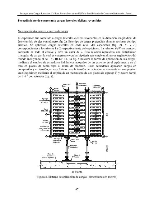
m<strong>un</strong>do incluyendo el <strong>de</strong>l DF, RCDF 93. La fig. 8 muestra la forma <strong>de</strong> aplicación <strong>de</strong> las <strong>cargas</strong>,<br />
medi<strong>ante</strong> el empleo <strong>de</strong> actuadores hidráulicos apoyados <strong>de</strong> <strong>un</strong> extremo en el espécimen y en el<br />
otro en placas <strong>de</strong> acero fijas al muro <strong>de</strong> reacción. Estos actuadores aplicaban <strong>cargas</strong> en<br />
compresión y en tensión, en este último caso la tensión <strong>de</strong>l actuador se convertía en compresión<br />
en el espécimen medi<strong>ante</strong> el empleo <strong>de</strong> <strong>un</strong> mecanismo <strong>de</strong> dos placas <strong>de</strong> espesor 2” y cuatro barras<br />
<strong>de</strong> 1 ¼ ” por actuador (fig. 8).<br />
A<br />
1<br />
Bor<strong>de</strong><br />
<strong>de</strong> losa<br />
Placa e=2"<br />
fija<br />
Dirección<br />
<strong>de</strong>l ensaye Columna<br />
2<br />
0.25x0.25<br />
3<br />
Articulación<br />
Eje viga<br />
longitudinal<br />
0.13x0.23<br />
Muro<br />
0.70x0.10<br />
B<br />
5.00<br />
Bor<strong>de</strong><br />
<strong>de</strong> losa<br />
Lingotes <strong>de</strong><br />
acero para la<br />
sobrecarga<br />
C<br />
eje viga<br />
port<strong>ante</strong><br />
0.15x0.28<br />
Placa e=2"<br />
móvil<br />
Actuador<br />
hidráulico<br />
Varilla<br />
Ø1 1/4"<br />
2.75±0.15<br />
Muro <strong>de</strong><br />
reacción<br />
0.85 <strong>de</strong> espesor<br />
Placa <strong>de</strong><br />
fijación<br />
2.30<br />
a) Planta<br />
Figura 8. Sistema <strong>de</strong> aplicación <strong>de</strong> <strong>cargas</strong> (dimensiones en metros)<br />
67