Pittway Tecnologica S.p.A., Via Caboto 19/3, 34147 ... - Cerber.pro
Pittway Tecnologica S.p.A., Via Caboto 19/3, 34147 ... - Cerber.pro
Pittway Tecnologica S.p.A., Via Caboto 19/3, 34147 ... - Cerber.pro

You also want an ePaper? Increase the reach of your titles
YUMPU automatically turns print PDFs into web optimized ePapers that Google loves.
INSTALLATION INSTRUCTIONS FOR PACKAGED ISOLATOR MODEL ISO524-1<br />
ISTRUZIONI PER L'INSTALLAZIONE DEL MODULO ISOLATORE, MODELLO ISO524-1<br />
GENERAL DESCRIPTION<br />
Before installing detectors, please thoroughly read the system wiring and installation manuals and review the ap<strong>pro</strong>priate national and local standards<br />
and codes of practice for the planning and installation of fire alarm systems.<br />
The System Sensor ISO524-1 short circuit isolator is designed for use with all 200, 500 and 700 series of analogue addressable detectors and modules.<br />
They prevent an entire communications loop from being disabled when a short circuit occurs. They accomplish this by isolating that part of the loop<br />
containing the short from the remainder of the circuit. These isolators also automatically restore the entire loop when the cause of the short circuit is<br />
corrected. The isolator has been designed such that if the short circuit occurs between adjacent ISO524-1 and / or B524IEFTx units, and no other<br />
<strong>pro</strong>ducts are connected between, the operation of the entire loop will remain intact in the event of this one short circuit, dependent on control panel<br />
operation.<br />
SPECIFICATIONS<br />
Length<br />
90mm max.<br />
Width<br />
35mm max.<br />
Height<br />
10mm max.<br />
Flying Lead Length<br />
120mm<br />
Flying Lead Cable<br />
Multi-strand 0.75mm²<br />
Operating Temperature Range -30°C to 70°C<br />
Operating Humidity Range<br />
0% to 95% Relative Humidity (Non-condensing)<br />
Operating Voltage<br />
15 to 28.5 VDC<br />
Standby Ratings<br />
100µA @ 24 VDC<br />
8µA @6VDC<br />
Isolation Current<br />
15mA at 24VDC<br />
Line impedance per base<br />
0.2 ohms max. @ 24 VDC<br />
WARNING Do not use high voltage continuity tester units, such as meggers, with Isolator modules connected.<br />
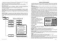
Figure 2. Typical Wiring Diagram<br />
( + )<br />
Compatible<br />
Device<br />
Control Device<br />
Panel<br />
Black<br />
( - ) ( - )<br />
MOUNTING<br />
Red<br />
The ISO524-1 Isolator may be installed in various convenient locations, such as junction boxes, behind sensor bases, within callpoint back-boxes, or<br />
within SMB500 module boxes.<br />
INSTALLATION GUIDELINES<br />
ISO524-1<br />
Red<br />
( A ) Note: Yellow<br />
wire not used<br />
( + )<br />
All wiring must be installed in compliance with all applicable local codes and any special requirements of the local authority having jurisdiction, using the<br />
<strong>pro</strong>per wire sizes. The conductors used to connect smoke detectors to control panels and accessory devices should be colour-coded to reduce the<br />
likelihood of wiring errors. Im<strong>pro</strong>per connections can prevent a system from responding <strong>pro</strong>perly in the event of a fire.<br />
For signal wiring (the wiring between interconnected detectors), it is recommended that the wire be no smaller than 0.5 mm 2 . However, wire sizes up<br />
to 2.5 mm 2 can be used with the isolator, using suitable cable connectors. The use of twisted pair wiring or shielded cable for the power (+ and -) loop is<br />
recommended to minimize the effects of electrical interference.<br />
If shielded cable is used, the shield connection to and from the isolator must be continuous by using wire nuts, crimping, or soldering, as ap<strong>pro</strong>priate, for<br />
a reliable connection.<br />
Alarm system control panels have specifications for allowable loop resistance. Consult the control panel specifications for the total loop resistance<br />
allowed before wiring the detector loops.<br />
1. Using suitable cable connectors, connect the incoming and outgoing loop positive cables to each of the two available red ISO524-1 cables.<br />
2. Connect the Yellow cable to Device +ve, in order to maintain device +ve irrespective of the position of the short circuit ( B ), otherwise do not<br />
connect ( A ).<br />
3. Connect the incoming, outgoing loop negative cables to the single black ISO524-1 cable and Device +ve.<br />
4. Check the entire loop wiring before applying power. This includes checking the wiring for continuity, correct polarity and ground fault testing.<br />
5. Once all loop cabling has been checked, power may be applied to the system and functional tests carried out.<br />
( - )<br />
Compatible<br />
Control<br />
Panel<br />
( + )<br />
Device<br />
( B ) Note: Yellow<br />
wire used<br />
Figure 1. Layout<br />
Black<br />
Red<br />
ISO524-1<br />
Device<br />
Yellow<br />
To Next Devices<br />
Red<br />
( - )<br />
( + )<br />
DESCRIZIONE GENERALE<br />
Prima di eseguire l’installazione dei rilevatori, leggere attentamente i manuali per l’installazione e il cablaggio del sistema e revisionare gli standard<br />
locali e nazionali e i codici relativi alla pianificazione e all’installazione di sistemi antincendio.<br />
L’isolatore di cortocircuito System Sensor ISO524-1 è <strong>pro</strong>gettato per l’uso con le serie 200, 500 e 700 di rilevatori e moduli analogici indirizzabili. Essi<br />
impediscono che il verificarsi di un cortocircuito <strong>pro</strong>vochi la disattivazione dell’intero cablaggio. La loro funzione consiste nell’isolare, dal resto del<br />
circuito, la parte del loop contenente il cortocircuito. Gli isolatori ripristinano inoltre automaticamente l’intero circuito, una volta che la causa del<br />
cortocircuito sia stata rimossa. L’isolatore è <strong>pro</strong>gettato in modo che, qualora il cortocircuito si verifichi tra le unità adiacenti ISO524-1 e/o B524IEFTx, e<br />
nessun altro <strong>pro</strong>dotto sia collegato tra i due, il funzionamento dell’intero loop resti intatto, a seconda del funzionamento del pannello di controllo.<br />
SPECIFICHE TECNICHE<br />
Lunghezza<br />
90mm max.<br />
Larghezza<br />
35mm max.<br />
Altezza<br />
10mm max.<br />
Lunghezza cavi<br />
120mm<br />
Tipo e sezione cavo multi-filo 0,75mm²<br />
Gamma di temperatura operativa da -30°C a 70°C<br />
Gamma di umidità operativa<br />
umidità relativa da 0% a 95% (priva di condensa)<br />
Gamma di tensione operativa<br />
da 15 a 28,5VCC<br />
Valori nominali della modalità di attesa<br />
100µA a 24VCC<br />
8µA a 6VCC<br />
Corrente di isolamento<br />
15mA a 24VCC<br />
Impedenza di linea per modulo<br />
0,2 Ohm max. a 24VCC<br />
AVVISO: Non utilizzare unità tester di continuità ad alta tensione, come megaohmetri, con moduli isolatori collegati.<br />
Figura 2. Tipico Schema di Cablaggio<br />
Figura .1 Layout<br />
( - )<br />
Rosso<br />
Rosso<br />
( + )<br />
( + ) Pannello<br />
Pannello<br />
ISO524-1<br />
di<br />
di<br />
Dispositivo Dispositivo Controllo Dispositivo Dispositivo<br />
Controllo<br />
Compatibile<br />
Compatibile<br />
Nero<br />
( - ) ( - ) ( + )<br />
( A ) Nota: Filo<br />
Giallo non utilizzato<br />
( B ) Nota: Filo Giallo<br />
utilizzato<br />
Rosso<br />
Rosso<br />
MONTAGGIO<br />
L’isolatore ISO524-1 può essere installato in vari siti idonei, ad esempio in scatole di giunzione, dietro a basi di sensori, all’interno di scatole per<br />
pulsanti di chiamata o all’interno di scatole del modulo SMB500.<br />
GUIDA PER L’INSTALLAZIONE<br />
È necessario che l’intero cablaggio venga installato in maniera conforme ai codici locali applicabili e agli specifici requisiti della giurisdizione locale,<br />
utilizzando un cablaggio di ap<strong>pro</strong>priate dimensioni. È opportuno che i conduttori utilizzati per collegare i rilevatori di fumo ai pannelli di controllo siano<br />
codificati a colori per ridurre la <strong>pro</strong>babilità di errori di cablaggio. Collegamenti im<strong>pro</strong>pri possono com<strong>pro</strong>mettere l’ap<strong>pro</strong>priata risposta del sistema in<br />
caso di incendio.<br />
Per il cablaggio del segnale (il cablaggio tra rilevatori interconnessi), si consiglia di non utilizzare dimensioni di cablaggio inferiori a 0,5 mm 2 . Tuttavia,<br />
è possibile utilizzare con l’isolatore dimensioni di cavi fino a 2,5 mm 2 , servendosi di ap<strong>pro</strong>priati connettori di cavi. Si consiglia l’uso di un cablaggio<br />
con cordone elettrico bipolare o cavo schermato per loop (+ e -), per minimizzare gli effetti dell’interferenza elettrica. Se si utilizza un cavo<br />
schermato, è necessario che la connessione alla schermatura, dal/all’isolatore, sia continua, utilizzando a questo scopo dadi, graffette o saldature, a<br />
seconda del caso, per garantire una connessione affidabile.<br />
I pannelli di controllo del sistema di allarme hanno specifiche tecniche per la resistenza ammissibile del loop. Fare riferimento alle specifiche tecniche<br />
del pannello di controllo per informarsi sulla resistenza totale consentita , prima di <strong>pro</strong>cedere al cablaggio dei rilevatori.<br />
1. Utilizzando connettori adeguati, collegare i cavi della linea positiva, sia quello in arrivo che quello in uscita, ad uno e all'altro dei due cavi<br />
rossi dell'ISO524-1.<br />
2. Collegare il cavo giallo a Device +ve per mantenere +ve non legata alla posizione del corto circuito, altrimenti non collegare.<br />
3. Collegare entrambe i cavi della linea negativi al cavo nero dell'ISO524-1 ed a Device -ve.<br />
4. Prima di applicare l’alimentazione, controllare l’intero cablaggio del loop. Tale operazione comprende la verifica del cablaggio per la<br />
continuità, della corretta polarità e della dispersione a terra.<br />
5. Dopo aver controllato tutti i cavi del loop, è possibile applicare l’alimentazione al sistema ed effettuare le verifiche del funzionamento vero e<br />
<strong>pro</strong>prio.<br />
<strong>Pittway</strong> <strong>Tecnologica</strong> S.p.A., <strong>Via</strong> <strong>Caboto</strong> <strong>19</strong>/3, <strong>34147</strong> Trieste, Italy 1 © System Sensor 2002 <strong>Pittway</strong> <strong>Tecnologica</strong> S.p.A., <strong>Via</strong> <strong>Caboto</strong> <strong>19</strong>/3, <strong>34147</strong> Trieste, Italy 2<br />
© System Sensor 2002<br />
D550-31-10 I56-1642-011 D550-31-10 I56-1642-011<br />
Nero<br />
ISO524-1<br />
Giallo<br />
( - )<br />
Ai<br />
Dispositivi<br />
Successivi<br />
( + )
DESCRIPCIÓN GENERAL<br />
INSTRUCCIONES DE INSTALACIÓN DEL AISLADOR COMPACTO MODELO ISO524-1<br />
Antes de instalar los detectores, lea atentamente los manuales de instalación y cableado del sistema y repase las normas nacionales y locales relativas<br />
a las prácticas de planificación e instalación de sistemas de alarma de incendios.<br />
El aislador de cortocircuitos ISO524-1 de System Sensor ha sido diseñado para utilizarse con todas las series 200, 500 y 700 de detectores analógicos<br />
direccionables y módulos. Éstos evitan la desactivación de todo el bucle de comunicaciones a causa de un cortocircuito. Esto se logra aislando la parte<br />
del bucle que contiene el cortocircuito del resto del circuito. Los aisladores también restablecen la parte correspondiente del bucle una vez corregido el<br />
cortocircuito. El aislador ha sido diseñado de tal manera que si se <strong>pro</strong>duce un cortocircuito entre dos aisladores ISO524-1 y/o B524IEFTx sin elementos<br />
conectados entre ambos, el funcionamiento del resto del bucle permanecerá inalterado en caso de cortocircuito en bucle cerrado, dependiendo del<br />
funcionamiento del panel de control.<br />
ESPECIFICACIONES<br />
Longitud:<br />
90mm máx.<br />
Ancho:<br />
35mm máx.<br />
Alto:<br />
10mm máx.<br />
Longitud de Cable de conexión:<br />
120mm<br />
Sección de Cable de conexión:<br />
Multifilamento 0,75mm²<br />
Margen de Temperatura de Funcionamiento: –30°C a 70°C<br />
Margen de Humedad en Funcionamiento: 0% a 95% de Humedad Relativa (sin condensación)<br />
Tensión de Funcionamiento:<br />
15 a 28,5 Vcc<br />
Figura 1. Aspecto<br />
Corriente en Reposo:<br />
100µA a 24 Vcc<br />
8µA a 6 Vcc<br />
Corriente en Aislamiento:<br />
15mA a 24Vcc<br />
Impedancia de la línea por aislador:<br />
0,2 ohms. máx. a 24 Vcc<br />
ATENCIÓN No utilice unidades de prueba de continuidad de alta tensión, tales como megóhmetros, con los aisladores conectados.<br />
Figura 2. Diagrama Normal de Cableado<br />
ALLGEMEINE BESCHREIBUNG<br />
ANLEITUNG FÜR DEN EINBAU VON KOMPAKTEN ISOLATOREN, MODELL ISO524-1<br />
Lesen Sie bitte vor dem Einbau von Meldern sorgfältig die Handbücher für die Verdrahtung und den Einbau, und sehen Sie die in Frage kommenden<br />
nationalen und lokalen Bestimmungen und Ausführungsvorschriften für die Planung und die Installation von Brandmeldesystemen durch.<br />
Der Kurzschluß-Isolator ISO524-1 von System Sensor ist für den Einsatz bei allen Meldern und Modulen der Serien 200, 500 und 700 geeignet. Er<br />
verhindert, daß ein kompletter Loop beim Auftreten eines Kurzschlusses ausfällt. Dies wird erreicht, indem der Teil des Loops, in dem der<br />
Kurzschluß auftritt, vom Rest des Loops abgetrennt wird. Diese Isolatoren stellen darüber hinaus die Gesamtfunktion des Loops wieder her, wenn die<br />
Ursache des Kurzschlusses beseitigt ist. Der Isolator ist so gestaltet, daß im Falle des Auftretens eines Kurzschlusses zwischen benachbarten<br />
ISO524-1 und/oder B524IEFTx (wobei keinerlei weitere Produkte dazwischen geschaltet sind) die Funktion der Gesamtschleife bei diesem einzelnen<br />
Kurzschluß in Abhängigkeit von der Betriebsweise der Brandmelderzentrale voll erhalten bleibt.<br />
Nachsatz: Sind zwischen den betroffenen Isolatoren weitere Elemente an den Loop angeschlossen, können diese nicht mit der Brandmelderzentrale<br />
kommunizieren, solange der Kurzschluss besteht.<br />
SPEZIFIKATIONEN<br />
Länge:<br />
90mm max.<br />
Breite:<br />
35mm max.<br />
Höhe:<br />
10mm max.<br />
Länge der losen Anschlußdrähte:<br />
120mm<br />
Querschnitt der losen Anschlußdrähte (Litze): 0,75mm²<br />
Betriebstemperaturbereich: –30°C bis 70°C<br />
Feuchtigkeitsbereich im Betrieb:<br />
0% bis 95% relative Feuchte (nichtkondensierend)<br />
Betriebsspannungsbereich:<br />
15 bis 28,5 VDC<br />
Abbildung 1. Aussehen<br />
Strom im Bereitschaftsmodus:<br />
100µA bei 24 VDC<br />
8µA bei 6 VDC<br />
Trennstrom:<br />
15mA bei 24 VDC<br />
Leitungsimpedanz <strong>pro</strong> Sockel:<br />
0,2 Ohm max. bei 24 VDC<br />
WARNUNG Verwenden Sie keine Isolationsprüfgeräte, wenn Isolatormodule angeschlossen sind.<br />
Abbildung 2. Schaltbild einer typischen Anordnung<br />
Rojo<br />
( + )<br />
Rojo ( + )<br />
Panel<br />
ISO524-1<br />
de Equipo<br />
Equipo<br />
Control<br />
Compatible<br />
Negro<br />
( - ) ( - )<br />
( A ) Nota: Cable<br />
Amarillo no utilizado<br />
( - )<br />
Pannello<br />
di<br />
Controllo<br />
Compatibile<br />
( + )<br />
Equipo<br />
( B ) Nota: Cable<br />
Amarillo utilizado<br />
Negro<br />
Equipo<br />
ISO524-1<br />
Amarillo<br />
( - )<br />
Al<br />
Siguiente<br />
Dispositivo<br />
( + )<br />
( + )<br />
Rot<br />
Rot<br />
( + )<br />
Kompatible<br />
ISO524-1<br />
Brandmelderzentrale<br />
Melder<br />
Melder<br />
( - )<br />
Schwarz<br />
( - )<br />
( A ) Zur Beachtung: Gelb draht<br />
nicht angeschlossen<br />
Rojo<br />
Rojo<br />
EINBAU<br />
Die Isolatoren ISO524-1 können an den unterschiedlichsten Stellen eingebaut werden, die sich dafür eignen, z.B. in Verbindungsdosen, hinter<br />
MONTAJE<br />
Meldersockeln, in Druckknopfmeldergehäusen oder in Modulboxen SMB500.<br />
El aislador ISO524-1, gracias a su reducido tamaño, se puede instalar en el interior de cajas de conexiones, debajo de las bases de los sensores, dentro EINBAUANLEITUNG<br />
de las cajas de pulsadores, o bien dentro de las cajas de módulos SMB500.<br />
Die Verkabelung muß in Übereinstimmung mit den jeweiligen lokalen Bestimmungen und gesetzlichen Vorschriften erfolgen; auf die Verwendung der<br />
NORMAS DE INSTALACIÓN<br />
richtigen Drahtquerschnitte ist zu achten. Für die Leitungen, die zur Verbindung von Rauchmeldern mit der Brandmelderzentrale und den<br />
Todo el cableado ha de instalarse de acuerdo con todas las normativas locales aplicables, y requerimientos especiales que determinen las autoridades Zubehöreinheiten verwendet werden, sollte zur Vermeidung von Verdrahtungsfehlern eine farbliche Codierung eingeführt werden. Bei einer<br />
locales con jurisdicción, respecto a la sección correcta de los conductores. Los hilos que se utilicen para conectar los dispositivos al panel de control y fehlerhaften Verdrahtung besteht die Gefahr, daß das System in Falle eines Brandes falsch reagiert.<br />
a los equipos accesorios han de estar codificados con colores para reducir la <strong>pro</strong>babilidad de errores en el cableado. Un conexionado incorrecto puede Der Drahtquerschnitt der Signalleitungen (die Leitungen zur Verbindung der Melder untereinander) sollte möglichst nicht geringer als 0,5 mm² sein.<br />
impedir que el sistema responda adecuadamente en caso de incendio.<br />
An das Isolatormodul können Drähte mit einem Querschnitt bis zu 2,5 mm² angeschlossen werden; verwenden Sie passende<br />
Para el cableado del bucle (el cableado entre detectores y dispositivos conectados al panel), se recomienda una sección no inferior de 0,5 mm 2 . En<br />
Kabelanschlußelemente. Für die Stromversorgung ist die Verwendung einer verdrillten oder abgeschirmten (+ und -) Doppelleitung empfehlenswert,<br />
cualquier caso, con el aislador se pueden utilizar secciones de cable de hasta 2,5 mm 2 , utilizando los conectores adecuados al cable. Se recomienda el<br />
um die Auswirkungen von elektrischen Störungen auf ein Mindestmaß zu begrenzen. Wenn ein abgeschirmtes Kabel verwendet wird, muß die<br />
Abschirmung zum und vom Isolatormodul elektrisch durchgeschleift werden; stellen Sie die Verbindung durch Schraubelemente, durch Crimpen oder<br />
uso de cable apantallado o de par trenzado para el lazo de alimentación (+ y -) para minimizar los efectos de interferencias eléctricas. Si se utiliza cable<br />
Löten her, je nachdem was sich für einen sicheren Kontakt als die geeignetste Lösung erweist.<br />
apantallado, la conexión de la malla (Independiente) y del bucle al aislador ha de ser continua utilizando regletas, conectores de presión o soldadura,<br />
Für Brandmelderzentralen gelten maximal zulässige Schleifenwiderstände. Vor der Verkabelung der Melder sollten Sie daher die Spezifikationen der<br />
según <strong>pro</strong>ceda, con el fin de obtener una conexión fiable.<br />
Brandmelderzentrale durchsehen, um sich über den zulässigen Gesamtschleifenwiderstand zu informieren.<br />
Los paneles de control de sistemas de alarma poseen especificaciones de resistencia máxima permisible en el bucle. Consulte las especificaciones del 1. Schliessen Sie die ein- und ausgehenden Plusleitungen der Schleife mit geeigneten Kabelanschlusselementen jeweils an einen roten Draht<br />
panel de control relativas a la resistencia total máxima permisible del bucle antes de conectar los bucles de los dispositivos.<br />
des ISO524-1 an.<br />
1. Utilice los conectores de cable adecuados y conecte los cables positivos del lazo de entrada y salida a los dos cables rojos ISO524-1<br />
2. Schliessen Sie den gelb Draht an den +ve Anschluß des Elements in der Kommunikationsschleife an, um die Funktion des Elements<br />
disponibles.<br />
unabhängig von der Lage eines auftretenden Kurzschlusses aufrecht zu erhalten. Wird der gelb Draht nicht angeschlossen ( Abb. A ), kann je<br />
2. Conecte el cable amarillo al positivo ( + ) del equipo para mantener el positivo del equipo con independencia de la posición de cortocircuito. De<br />
nach Lage eines auftretenden Kurzschlusses die Kommunikation mit dem Element der Schleife verloren gehen .<br />
lo contrario, no lo conecte.<br />
3. Schliessen Sie die ein- und ausgehende Minusleitung der Schleife an den einzelnen schwarzen Draht des ISO524-1 und an den -ve Anschluß<br />
des Elements in der Kommunikationsschleife an.<br />
3. Conecte los cables negativos del lazo de entrada y salida al cable negro ISO524-1 y al negativo ( - ) del equipo.<br />
4. Überprüfen Sie noch einmal die Verdrahtung des gesamten Loops, bevor Sie die Spannungsversorgung anschließen. Dazu gehört auch die<br />
4. Compruebe la totalidad del cableado del bucle antes de conectar la alimentación eléctrica. Esto incluye la com<strong>pro</strong>bación de los conductores<br />
Überprüfung auf elektrische Durchgängigkeit und richtige Polarität sowie ein Test auf Erd- bzw. Masseschluss.<br />
respecto a la continuidad, la polaridad adecuada y las pruebas de derivación a tierra.<br />
5. Nach Überprüfung der gesamten Verkabelung kann die Stromversorgung angeschlossen werden, und es können Funktionstests durchgeführt<br />
5. Una vez com<strong>pro</strong>bado el cableado del bucle se puede aplicar tensión eléctrica al sistema y ejecutar las pruebas de funcionalidad.<br />
werden.<br />
<strong>Pittway</strong> <strong>Tecnologica</strong> S.p.A., <strong>Via</strong> <strong>Caboto</strong> <strong>19</strong>/3, <strong>34147</strong> Trieste, Italy 3 © System Sensor 2002 <strong>Pittway</strong> <strong>Tecnologica</strong> S.p.A., <strong>Via</strong> <strong>Caboto</strong> <strong>19</strong>/3, <strong>34147</strong> Trieste, Italy 4<br />
© System Sensor 2002<br />
D550-31-10 I56-1642-011 D550-31-10 I56-1642-011<br />
( - )<br />
( + )<br />
Melder<br />
( B ) Zur Beachtung: Gelb<br />
draht angeschlossen<br />
Schwarz<br />
Rot<br />
ISO524-1<br />
Melder<br />
Gelb<br />
Rot<br />
( - )<br />
Zu<br />
den<br />
nchsten<br />
Einheiten<br />
( + )