Create successful ePaper yourself
Turn your PDF publications into a flip-book with our unique Google optimized e-Paper software.
- In the case of breakdown or modification of the apparatus<br />
of the system (such as power supplier...) please<br />
contact a specialized maintenance service.<br />
D<br />
BEDIENUNGS- UND<br />
INSTALLATIONSANLEITUNG<br />
2<br />
A<br />
1<br />
2<br />
4<br />
5<br />
6<br />
7<br />
Personal door-bell button<br />
The monitor fits a landing call input with a two-tone<br />
call, fig. 11.<br />
Connecting YPL unit<br />
When the YPL unit is installed in the receiver, wire jumper<br />
BP1 must be cut (fig. 10).<br />
<strong>YKP</strong>/<strong>200+YV</strong>C COLOR MONITOR WITH HANDSET<br />
Features similar to <strong>YKP</strong>/<strong>200+YV</strong>, it has a colour saturation<br />
control instead of the contrast control (fig. 1).<br />
<strong>YKP</strong>/200+YP3+YV (<strong>YVC</strong>) INTERCOM MONITOR<br />
WITH HANDSET<br />
Used to manage up to 6 intercom units with 6 call buttons<br />
(two YP3).<br />
The monitor permits to identify the source of a call: a<br />
continuous call tone identifies calls from other intercom<br />
units and a two-tone call identifies calls from the external<br />
entry panel (or from the landing). A call from the<br />
entry panel during an internal conversation between<br />
two intercom units is indicated by the activation of the<br />
monitor and the emission of a low acoustic signal. In<br />
this case, communication with the entry panel (and<br />
hence the possibility of activating both the door release<br />
control and the stairs light relay) may be established by<br />
hanging the handset of the intercom unit currently in<br />
use and lifting the handset of the one signalling a call.<br />
SW1 switch<br />
This switch (fig. 10), normally set to STD (standard<br />
mode), must be switched to INT when wanting to use<br />
the receiver as an intercom unit.<br />
Entry panel selection in systems<br />
with several entrances<br />
The VSI/200 selector allows you to select the external<br />
entry panel or camera from the monitor in sequential<br />
mode. To operate the selector: press the entry panel<br />
activation button to turn-on the monitor; and then press<br />
the auxiliary button (•) to select the entry panels.<br />
NOTE. In the event a call is made from the entry panel,<br />
the selection in progress is interrupted.<br />
If the external call is addressed to the monitor making the<br />
selection, the monitor displays the image filmed at the<br />
external entry from where the call is addressed to another<br />
monitor, the image disappears from the monitor.<br />
Function of each terminal (fig. 10)<br />
Terminal block M1<br />
3 video signal<br />
coaxial cable<br />
4 video signal shield<br />
If the video line ends at this monitor, connect a 75Ω (violetgreen-black-gold)<br />
resistor between terminals 3 and 4.<br />
3 pos. video signal<br />
twisted pair<br />
4 neg. video signal<br />
If the video line ends at this monitor, connect a 56Ω (greenblue-black-gold)<br />
resistor between terminals 3-5 and 4-5.<br />
5 – 14÷17,5V<br />
6 + supply voltage to monitor<br />
7 call input from entry panel<br />
8 audio to monitor<br />
9 audio to entry panel<br />
10 Aux - auxiliary services<br />
11 (24V 1A)<br />
12 call input from intercom receiver<br />
18 stairs light<br />
19 auto-switch on<br />
20 call input from landing<br />
Terminal block M2 (accessories)<br />
connection for<br />
YAL loudspeaker<br />
7A connection for YPL module<br />
Technical features <strong>YKP</strong>/200<br />
• Supply voltage: 14÷17,5VDC.<br />
• Current demand: max. 10 mA quiescent.<br />
• Bandwidth response at -3dB: 5MHz.<br />
• Video input: 1Vpp from coaxial line; + video signal<br />
0,6Vpp, - video signal 0,6Vpp from differential line<br />
(twisted pair).<br />
• Video input impedance: ≥22kΩ<br />
• Call signal: two-tone call signal from the entry panel or<br />
from the landing and continuous tone call signal from<br />
intercom calls.<br />
• Audio secrecy to entry panel.<br />
• Working temperature range: from 0 °C to +35 °C.<br />
• Dimensions: 205x215x63mm.<br />
The monitor is protected by the slow blow fuse F1 - T<br />
630mA - located on monitor’s printed card, fig.10.<br />
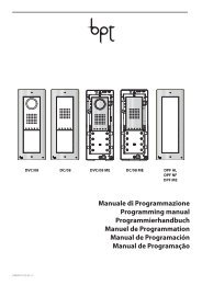
INSTALLATION<br />
WARNING. It is recommended to install the monitor<br />
in a dry place.<br />
The wall mounting can be installed following the<br />
instructions in figures 2-5. Fit the monitor module on the<br />
wall mounting as illustrated in figures 6-8. To remove<br />
the monitor module, prise it off by inserting a screwdriver<br />
in the slot in the housing (fig. 9). To remove the <strong>YKP</strong><br />
cover, use a screwdriver inserted in the slot (fig. 4).<br />
WANDHALTER MIT HÖRER <strong>YKP</strong>/200<br />
Diese Halterung ist für den Einsatz des<br />
Bildschirmmoduls YV oder <strong>YVC</strong> sowie der Einheiten<br />
YP3 und YPL in den Anlagen des Systems 200 voreingestellt.<br />
Falls eine Ruftonverstärkung erforderlich sein sollte,<br />
ist auch der Einsatz des Lautsprechers YAL möglich.<br />
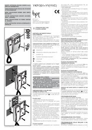
VIDEOSPRECHGARNITUR MIT HÖRER <strong>YKP</strong>/200+ YV<br />
Monitor Mitseh- und Mithörgesperrt für den Videosignalempfang<br />
über Koaxial- oder Telefonkabel.<br />
Mit folgenden Schaltelementen (Abb. 1):<br />
Türöffnertaste ( 1 )<br />
Außenstationeneinschaltung ( 2 )<br />
• Zusatz-Zentralsteuerung (Treppenlicht,<br />
Kamerawahltaste) ( 1 )<br />
• Zusatzsteuerung<br />
Helligkeit<br />
Kontrast<br />
( 1 ) Schaltelementen sind nur bei eingeschaltetem<br />
Monitor steuerbar.<br />
( 2 ) Die Einschaltung des Gerätes und der anschließende<br />
Anschluß an die Außenstation sind nur<br />
möglich, wenn die Anlage nicht besetzt ist.<br />
HINWEISE FÜR DEN NUTZER<br />
- Bitte Gerät nicht öffnen oder aufbrechen (hohe<br />
Spannung!).<br />
- Zur Vermeidung eines Bildröhrenbruchs, Stösse<br />
und Schläge unterlassen.<br />
- Bei Störungen, Änderungen oder Reparaturen an<br />
den Geräten (Netzgerät, usw.) nur an Spezialisten<br />
wenden.<br />
Etagenanruf<br />
Das Gerät verfügt über einen Eingang für die<br />
Etagenanruf mit Zweiklangton (Abb. 11).<br />
Anschluss der Einheit YPL<br />
Beim Einbau der Einheit YPL in die Sprechgarnitur ist<br />
der bündige Verteilerschaltdraht BP1 abzunehmen<br />
(Abb. 10).<br />
FARBVIDEOSPRECHGARNITUR MIT HöRER<br />
<strong>YKP</strong>/<strong>200+YV</strong>C<br />
Dem Modell <strong>YKP</strong>/<strong>200+YV</strong> ähnlich; anstelle der<br />
Kontrasteinstellung mit Farbsättigungsregelung<br />
ausgestattet (Abb. 1).<br />
INTERCOM-VIDEOSPRECHGARNITUR MIT<br />
HÖRER <strong>YKP</strong>/200+YP3+YV (<strong>YVC</strong>)<br />
Steuert über 6 Ruftasten (2 YP3) bis zu 6<br />
Nebenstellenanschlüssen.<br />
Das Gerät macht die Herkunft des Anrufes erkennbar<br />
durch Dauerton für Anrufe von anderen Intercom-<br />
Stellen und Zweiklangton für Anrufe von der<br />
Außenstation (oder von der Etage).<br />
Ein Anruf von der Außenstation während eines<br />
Gespräches zwischen Innensprechstellen wird durch<br />
die Einschaltung des Monitors sowie eines schwachen<br />
Tonsignals im Hörer angezeigt.<br />
In diesem Fall kann das Gespräch mit der<br />
Außenstation (und damit die Betätigung des Türöffners<br />
und des Treppenlichtes) durch Auflegen der Hörer<br />
und Abheben des Hörers an der angerufenen<br />
Innensprechstelle aufgenommen werden.<br />
Umschalter SW1<br />
Falls die Innensprechstelle für den Intercom-Betrieb<br />
voreingestellt wurde, ist dieser gewöhnlich auf STD<br />
(Standardbetrieb) positionierte Umschalter (Abb. 10)<br />
auf INT zu setzen.<br />
Auswahl der Außenstation bei<br />
Anlagen mit mehreren Eingängen<br />
Der Wahlschalter VSI/200 ermöglicht die Auswahl der<br />
Außenstation oder des Aufnahmegeräts über den<br />
Bildschirm auf sequentielle Weise.<br />
Um diese Betriebsart einzuschalten, die Taste<br />
Außenstation Einschalten zu betätigen, um den<br />
Monitor einzuschalten, und danach die Zusatztaste<br />
(•) zwecks Auswahl der Außenstationen.<br />
HINWEIS. Ein eventuell von der Außenstation kommender<br />
Ruf unterbricht den Auswahlvorgang und, falls<br />
der Ruf für die gleiche interne Nebenstelle bestimmt<br />
ist, erscheint auf dem Bildschirm das Bild, das an der<br />
Außenstation aufgenommen wurde, von der aus der<br />
Ruf erfolgt ist.<br />
Sollte der Ruf dagegen für eine andere interne<br />
Nebenstelle bestimmt sein, so verschwindet das Bild<br />
vom Bildschirm.<br />
Belegung der Klemmleiste (Abb. 10)<br />
Klemmleiste M1<br />
3 Videosignal<br />
Koaxial-Kabel<br />
4 Videosignalabsch.