The Torto⢠Ceiling Fan - Fanimation
The Torto⢠Ceiling Fan - Fanimation
The Torto⢠Ceiling Fan - Fanimation

You also want an ePaper? Increase the reach of your titles
YUMPU automatically turns print PDFs into web optimized ePapers that Google loves.
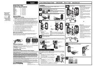
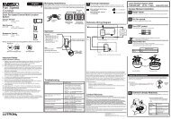
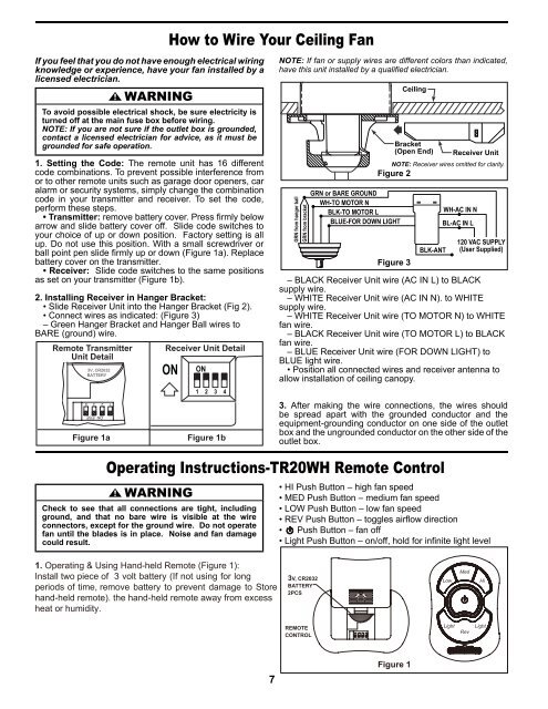
If you feel that you do not have enough electrical wiringknowledge or experience, have your fan installed by alicensed electrician.▲WARNINGTo avoid possible electrical shock, be sure electricity isturned off at the main fuse box before wiring.NOTE: If you are not sure if the outlet box is grounded,contact a licensed electrician for advice, as it must begrounded for safe operation.1. Setting the Code: <strong>The</strong> remote unit has 16 differentcode combinations. To prevent possible interference fromor to other remote units such as garage door openers, caralarm or security systems, simply change the combinationcode in your transmitter and receiver. To set the code,perform these steps.• Transmitter: remove battery cover. Press firmly belowarrow and slide battery cover off. Slide code switches toyour choice of up or down position. Factory setting is allup. Do not use this position. With a small screwdriver orball point pen slide firmly up or down (Figure 1a). Replacebattery cover on the transmitter.• Receiver: Slide code switches to the same positionsas set on your transmitter (Figure 1b).2. Installing Receiver in Hanger Bracket:• Slide Receiver Unit into the Hanger Bracket (Fig 2).• Connect wires as indicated: (Figure 3)– Green Hanger Bracket and Hanger Ball wires toBARE (ground) wire.Remote Transmitter Receiver Unit DetailUnit DetailHow to Wire Your <strong>Ceiling</strong> <strong>Fan</strong>NOTE: If fan or supply wires are different colors than indicated,have this unit installed by a qualified electrician.GRN from hanger ballGRN from bracketGRN or BARE GROUNDWH-TO MOTOR NBLK-TO MOTOR LBLUE-FOR DOWN LIGHTBracket(Open End) Receiver UnitNOTE: Receiver wires omitted for clarity.Figure 2Figure 3<strong>Ceiling</strong>BLK-ANTWH-AC IN NBL-AC IN L120 VAC SUPPLY(User Supplied)– BLACK Receiver Unit wire (AC IN L) to BLACKsupply wire.– WHITE Receiver Unit wire (AC IN N). to WHITEsupply wire.– WHITE Receiver Unit wire (TO MOTOR N) to WHITEfan wire.– BLACK Receiver Unit wire (TO MOTOR L) to BLACKfan wire.– BLUE Receiver Unit wire (FOR DOWN LIGHT) toBLUE light wire.• Position all connected wires and receiver antenna toallow installation of ceiling canopy.Figure 1aFigure 1b3. After making the wire connections, the wires shouldbe spread apart with the grounded conductor and theequipment-grounding conductor on one side of the outletbox and the ungrounded conductor on the other side of theoutlet box.Operating Instructions-TR20WH Remote Control▲WARNINGCheck to see that all connections are tight, includingground, and that no bare wire is visible at the wireconnectors, except for the ground wire. Do not operatefan until the blades is in place. Noise and fan damagecould result.• HI Push Button – high fan speed• MED Push Button – medium fan speed• LOW Push Button – low fan speed• REV Push Button – toggles airflow direction• Push Button – fan off• Light Push Button – on/off, hold for infinite light level1. Operating & Using Hand-held Remote (Figure 1):Install two piece of 3 volt battery (If not using for longperiods of time, remove battery to prevent damage to Storehand-held remote). the hand-held remote away from excessheat or humidity.3V, CR2032BATTERY2PCSREMOTECONTROL7Figure 1