Product Manual - Del Mar Fans and Lighting
Product Manual - Del Mar Fans and Lighting
Product Manual - Del Mar Fans and Lighting

Create successful ePaper yourself
Turn your PDF publications into a flip-book with our unique Google optimized e-Paper software.
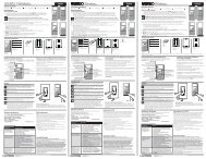
Bloom Ceiling Fan<br />
BL52<br />
Installation Instructions<br />
Instrucciones de instalación<br />
Instructions d’installation
1<br />
Read <strong>and</strong> Save These Safety Precautions<br />
1. Turn off electricity at main switch before wiring or servicing fan in order to avoid<br />
possible electrical shock.<br />
2. All wiring must be in accordance with the National Electric Code (ANSI/NFPA70-1999) <strong>and</strong> local<br />
electrical codes. Electrical installation should be performed by a qualified licensed electrician.<br />
3. After making the wire connections, the wires should be spread apart with the grounded<br />
conductor <strong>and</strong> the equipment-grounding conductor on the one side of the outlet box<br />
<strong>and</strong> the ungrounded conductor on the other side of the outlet box.<br />
4. The splices after being made should be turned upward <strong>and</strong> pushed carefully up into the outlet box.<br />
5. Conductor of a fan identified as grounded conductor to be connected to grounded conductor of power<br />
supply, conductor of a fan identified as ungrounded conductor to be connected to an ungrounded<br />
conductor of power supply, conductor of fan identified for equipment grounding to be connected<br />
to an equipment-grounding conductor.<br />
6. Fan should not be mounted in an area where it might get wet.<br />
7. To reduce the risk of fire, electric shock or personal injury, mount to outlet box marked<br />
"Acceptable for Fan Support" <strong>and</strong> use mounting screws provide with the outlet box.<br />
The outlet box <strong>and</strong> its support must be able to support the moving weight of the fan (at least 35lbs).<br />
8. For safety <strong>and</strong> best operating results, we recommend that you have a qualified<br />
electrician assemble <strong>and</strong> install your fan.<br />
9. WARNING: To reduce the risk of fire or electric shock, use the fan only with solid state speed control<br />
device provided.<br />
10. To reduce the risk of personal injury, do not bend the blade brackets when installing the brackets,<br />
balancing the blades or cleaning the fan. Do not insert foreign objects in between rotating fan blades.<br />
11. Net Weight: The weight of the complete fan, including assembly hardware is 30.64 lbs.<br />
Trouble Shooting<br />
Problem A: Fan Will not Start<br />
Remedies:<br />
1. Check fuse or circuit breaker <strong>and</strong> replace if necessary<br />
2. Turn off electrical power <strong>and</strong> check all wire connectors.<br />
3. Check on/off TCS <strong>and</strong> wall control selector switch. See operation instructions.<br />
Problem B: Fan is Excessively Noisy<br />
Remedies:<br />
1. Check that all screws in fan assembly are tight <strong>and</strong> properly seated.<br />
2. Check to make sure mounting bracket is installed properly.<br />
3. Check to make sure light kit <strong>and</strong> glass are installed properly <strong>and</strong> tight.<br />
4. If wall control is used, insure the wall control is not a transformer or a variable speed type.<br />
Problem C: Fan Wobbles<br />
Remedies:<br />
1. Check that all blades are screwed firmly into blade holders.<br />
2. Check that all blade holders are screwed firmly into motor.<br />
3. Check the weight of blades. All our blades are weighed on electronic scales. The weight is<br />
marked on the reverse side of the fan blade near the motor end. All of the blades should be<br />
the same weight to prevent fan from wobbling.<br />
4. A balancing kit is enclosed if needed.
2<br />
Before Assembly<br />
1. Make sure that the fan voltage (120) is compatible with your own electrical<br />
system.<br />
2. Check to make sure that your carton contains all the parts mentioned in the<br />
parts list.<br />
NOTE: The box can be used as a work space to prevent any damage on the<br />
ornamental surface.<br />
CAUTION: Before installing, choose a location for mounting the fan where the<br />
blades have at least 7 feet of clearance from all objects <strong>and</strong> floor. Mount an<br />
outlet box to the ceiling or use an existing box<br />
CAUTION: Do not mount fan to sheet rock or drywall type materials. To<br />
insure proper support, use the two #1 wood screws to secure mounting bracket<br />
to joist or beam. If the location you choose does not have a suitable support<br />
beam, install a 2”x 4” brace between ceiling joists to support.<br />
Screw Package<br />
S1. Wood Screws & Washers<br />
S2. Screws (for Canopy)<br />
S3. Bracket Screws & Washers<br />
S4. Blade Screws<br />
S5. Wire Connectors<br />
S6. Safety Bolt & Nut<br />
S7. "J" Hook<br />
S8. Zip Tie<br />
Quantity<br />
2<br />
3<br />
2<br />
3<br />
1<br />
1<br />
1<br />
Hardware<br />
Inventory<br />
S4<br />
S3<br />
S2<br />
S1<br />
S5<br />
S7<br />
S6<br />
Tools you Need<br />
1. Phillips Screwdriver<br />
3. Adjustable Wrench<br />
What You Have<br />
Parts<br />
1. Mounting Bracket<br />
2. Down Rod Assembly<br />
4" Rod Supplied<br />
3. Canopy<br />
4. Flange Cover<br />
5. Fan Housing & Motor<br />
6. Light Kit Glass<br />
7. Small Pedal Blades<br />
8. Large Pedal Blades<br />
9. TCS H<strong>and</strong> Held Control<br />
Quantity<br />
1<br />
1<br />
1<br />
1<br />
1<br />
1<br />
4<br />
4<br />
1<br />
1<br />
3<br />
5<br />
2<br />
4<br />
6<br />
2. Flat Screwdriver<br />
8<br />
7 9<br />
4.Wire Strippers
3<br />
Turn off circuit breakers <strong>and</strong> wall switch to the fan supply line leads.<br />
Preparation<br />
Important: When using an existing outlet box, be sure the box is<br />
securely attached to the building structure <strong>and</strong> can support the full<br />
weight of the fan. Failure to do so can result in serious injury or death.<br />
<br />
<br />
b.) Angle Mount<br />
<br />
IMPORTANT: If using the angle mount method, check to make sure the ceiling angle is<br />
not steeper than 35º. Angles greater than 35º will require a 45º angle adapter.<br />
30”<br />
84”
4<br />
Installing Mounting Bracket<br />
Support Beam<br />
Ceiling<br />
“J” Hook (S8)<br />
OUTLET BOX<br />
Outlet Box (A)<br />
Bracket Screws<br />
& Washers (S3)<br />
Mounting Bracket (1)<br />
Wood Screws (S1)<br />
Canopy Screws (S2)<br />
Wood Screws (S1)<br />
NOTE: Do not mount directly to sheet rock or ceiling tile.<br />
Prior to securing mounting bracket, screw "J" hook (S8) into ceiling outlet box<br />
as a secondary support means. Secure mounting bracket (#1) to the outlet box<br />
(A) by tightening bracket screws & washers (S3) as shown. If not mounting to<br />
an outlet box, use wood screws (S1) <strong>and</strong> washers (S3) <strong>and</strong> mount securely to<br />
ceiling beam. Be sure at this point to insert canopy screws (S2) in bracket.
5<br />
Unscrew <strong>and</strong> remove motor housing washer <strong>and</strong> motor housing top plate.<br />
Attach Large Pedal Blades from Top of Motor Housing.
6<br />
Reattach the Motor housing Plate <strong>and</strong> Motor Housing Washer as shown.<br />
Make sure the antenna wire is threaded through hole on top of motor housing.<br />
Downrod Assembly<br />
Locate downrod assembly (#2). Loosen ball screw on black hanging ball to<br />
free lock pin. Black hanging ball will slide down. Remove ground screw <strong>and</strong><br />
green ground wire. Remove hanging ball from downrod <strong>and</strong> save all parts.
7<br />
Insert fan wires through downrod.<br />
Thread the downrod onto the motor housing<br />
making sure the wires don’t get twisted.<br />
Insert safety bolt (S7) through flange & downrod<br />
<strong>and</strong> attach nut. Tighten firmly.<br />
Tighten set screw (A) against downrod.
8<br />
Place flange cover (4) over downrod assembly.<br />
Attach antenna wire to flange cover.<br />
Place canopy screw cover over downrod.<br />
Place canopy (3) over downrod (2).<br />
WARNING: Failure to completely tighten downrod as described in<br />
steps above could result in the fan loosening <strong>and</strong> possibly falling.<br />
Replace hanging ball, insert hanging pin through downrod <strong>and</strong> tighten set<br />
screw "C" in hanging ball into downrod.
9<br />
Lift fan onto the mounting bracket (#1). Turn housing until hanging ball seats<br />
itself into ball socket (listen for click).<br />
For added security, attach safety cable from fan unit to "J" hook (S8) in outlet<br />
box. Secure by looping zip tie (S9) through safety cable <strong>and</strong> "J" hook. Tighten<br />
zip tie securely.<br />
WARNING: To reduce the risk of fire, electric shock or personal injury,<br />
mount so outlet box marked "acceptable for fan support" <strong>and</strong> use mounting<br />
screws provided with the outlet box. Most outlet boxes commonly used for<br />
the support of lighting fixtures are not acceptable for fan support <strong>and</strong> may<br />
need to be replaced. Consult a qualified electrician if in doubt.
10<br />
Ground<br />
White (Neutral)<br />
Black<br />
(Power)<br />
White<br />
Black<br />
Blue<br />
Wire<br />
Connectors<br />
(S6)<br />
Ground<br />
(Green)<br />
Outlet Box<br />
Ground (Green)<br />
Downrod<br />
Ground<br />
(Green)<br />
Mounting Bracket<br />
Ground (Green)<br />
1. Connect fan wires to ceiling<br />
wires: white fan wire to white<br />
outlet wire, black to black <strong>and</strong><br />
green to green. Wire connectors<br />
(S6) are provided for your convenience.<br />
If an additional blue wire is<br />
present then also connect the blue<br />
wire to the black wire. (Optional<br />
light kit may be wired to individual<br />
wall switches, if desired.)<br />
2. After connections are made with<br />
wire connectors, turn splices<br />
upward <strong>and</strong> push carefully into<br />
outlet box. Separate blue <strong>and</strong> black<br />
wires on one side of the box, <strong>and</strong><br />
white <strong>and</strong> green wires on the other<br />
side.<br />
There are up to four wires coming from the<br />
top of the motor (including ground wire).
11<br />
Attach canopy (3) to the mounting bracket<br />
by placing screws (S2) into slot in canopy.<br />
Twist clockwise to lock into place.<br />
Tighten screws firmly.<br />
Seat the canopy screw cover into slots<br />
<strong>and</strong> twist to lock.
12<br />
Slide the small pedal blades into place, support <strong>and</strong><br />
attach with screws. (S4)<br />
Screw in c<strong>and</strong>elabra light bulbs. (not included)<br />
Place light kit glass over bulbs twist to<br />
lock into place.
Remote Control Operation Instructions<br />
ON/OFF<br />
HIGH<br />
MEDIUM<br />
LOW<br />
REVERSE<br />
FAN OFF<br />
For emergency shut off.<br />
Controls fan motor speed. To select desired speed, press<br />
button once <strong>and</strong> release.<br />
Controls direction of fan blades. To reverse fan blades, press<br />
once <strong>and</strong> release.<br />
Turns fan motor speed off. Press once to turn off. To start<br />
motor speed again, hit one of the motor speed buttons.<br />
L-1 Controls no function on this fan.<br />
L-2 Controls the on/off <strong>and</strong> intensity for optional light kit. Push<br />
<strong>and</strong> release for on/off function. Hold down for full range light<br />
dimming.<br />
NOTE:<br />
The “High”, “Medium” or “Low” buttons may be used to start<br />
the fan motor. The speed of the fan may be changed at anytime.