TA-3 REV 3.pmd - Air Systems International
TA-3 REV 3.pmd - Air Systems International
TA-3 REV 3.pmd - Air Systems International
- No tags were found...

You also want an ePaper? Increase the reach of your titles
YUMPU automatically turns print PDFs into web optimized ePapers that Google loves.
<strong>TA</strong>BLE OF CONTENTSOverview..........................................................................................................................................3Setup Procedure for Model <strong>TA</strong>-3...................................................................................................3Setup Procedure for Model <strong>TA</strong>-3EA..............................................................................................4Shutdown..........................................................................................................................................4Oil Change Procedure.....................................................................................................................5Sight Glass & Oil Cooler Information............................................................................................5Removal of <strong>Air</strong> Intake Filter..........................................................................................................6Replacing Oil Separator Element...................................................................................................6Replacing <strong>Air</strong> Intake Filter.............................................................................................................6Service Schedule.............................................................................................................................7Ordering Information......................................................................................................................7Parts Identification..........................................................................................................................7Warranty Disclaimer.....................................................................................................................18CONTIENDODescripción General.......................................................................................................................8Procedimento de Preparacion--Modelo <strong>TA</strong>-3................................................................................8Procedimento de Preparación--Modelo <strong>TA</strong>-3EA...........................................................................9Parada..............................................................................................................................................9Procedimiento de Cambio de Aceite............................................................................................10Información del Vidrio de Nivel y Enfriador de Aceite...............................................................10Remonción del Filtro de Admisión de <strong>Air</strong>e..................................................................................11Cómo Retirar el Elemento Separador de Aceite.........................................................................11Sustitución del Filtro de Admisión de <strong>Air</strong>e...................................................................................11Programa de Servicio....................................................................................................................12Información Para Ordenar............................................................................................................12Ensemble Completo de <strong>TA</strong>-3 y <strong>TA</strong>-3EA.......................................................................................12Denegación de la Garantía...........................................................................................................18<strong>TA</strong>BLE DES MATIERESVue d’Ensemble.............................................................................................................................13Procedure d’Installation--Modèle <strong>TA</strong>-3.......................................................................................13Procedure d’Installation--Modèle <strong>TA</strong>-3EA..................................................................................14Arret...............................................................................................................................................14Procédure de Vindage d’Huile......................................................................................................15Fenêtre d’Indication et Refroidisseir d’Huile..............................................................................15Retrait du Filtre d’Admission d’<strong>Air</strong>..............................................................................................16Remplacement de l’Element Separateur d’Huile........................................................................16Remplacement du Filtre d’Admission de l’<strong>Air</strong>...........................................................................16Programme d’Entretien................................................................................................................17Informations Relatives aux Commandes.....................................................................................17Montage Complet de <strong>TA</strong>-3 et <strong>TA</strong>-3EA........................................................................................17Limitations de la Garantie............................................................................................................18Revision 2 January 2001Page 2
BEFORE INITIAL S<strong>TA</strong>RT-UP ENSURE THAT THE COMPRESSOR OIL CHAMBER IS FILLED TO THECORRECT LEVEL WITH AIR SYSTEMS APPROVED OIL.OVERVIEWThe <strong>TA</strong>-3 is a portable, 3-man breathing air compressor designed exclusively for use with pressure demandrespirators. This system operates on standard 115 volt/60hz/20 amp electrical service. The system producespressure up to 110psi (7.5 bar) that is monitored by a built in pressure gauge. Note: The <strong>TA</strong>-3 must have a Grade-Dfiltration unit attached to the compressor to make a complete breathing air package. Any 30 or 60 minute aircylinder can be slid into the <strong>TA</strong>-3 frame and with the addition of a pressure reducing regulator and an Auto-<strong>Air</strong>Breather Box, you now have a 3-man compressor with full automatic backup air for IDLH operation (Model COMP-3EA). The compressor should be connected to the filtration unit with a minimum 0.5 inch I.D. breathing air hose.CONS<strong>TA</strong>NT FLOW RESPIRATORS CANNOT BE USED WITH THIS SYSTEM!Note: Always run, store, or ship the compressor in the horizontal position. Never stand the unit upright asoil will drain from the sump and cause damage to the compressor. Check compressor oil level before each usage.A 7/8" wrench is required to loosen the nut on the oil sump. Oil should be level with the bottom of the internalthreads. DO NOT OVERFILL. If oil level is low, add only <strong>Air</strong> <strong>Systems</strong>' approved oil. Order part number HP-268USDA synthetic lubricant.SETUP PROCEDURE - MODEL <strong>TA</strong>-3ENVIROWarning: Always locate compressor in a fresh air environment away from toxic dusts, vapors, and fumes.STEP 5)Adjust the regulator on the Grade-D filtration unit to the requiredoutput pressure (psi) of the pressure demand respirator. Reviewmanual on the Grade-D filtration unit and carbon monoxide monitorfor details on operation, service, and calibration before commencingwork. Attach and don respirator.STEP 1)Compressor must be attached to a Grade-D filtration unit. A minimum 1/2” I.D. hoseis to be used between the compressor andthe Grade-D filtration unit.STEP 4)Attach respirator supply hose to outlet fittingson Grade-D filtration unit. Never leave an open(unused) respirator attached to the system asoutput pressure will not be maintained.STEP 2)Plug compressor into a 115 voltreceptacle with a dedicated 20 ampservice. Note: If an extensioncord is going to be used, the cordmust be rated for a minimum 20amp service (12/3 gauge).STEP 3)Turn on the compressor and note the gaugepressure reading on the compressor. Allowtwin receiver tanks to fill to systempressure 110psi (7.5 bar) output.Note: Do not replace the coupling supplied on the compressortank outlet except with a checked style coupling of at least 1/2”I.D. Do not use a Chicago style coupling on this type of compressor.Page 3 Revision 2 January 2001
STEP 7)Adjust the regulator on the Grade-D filtration unit to the required outputpressure (psi) of the pressure demand respirator. Review manual on theGrade-D filtration unit and carbon monoxide monitor for details on operation,service, and calibration before commencing work. Attach and don respirator.STEP 1)Compressor must be attached to a Grade-Dfiltration unit. A minimum of 1/2” I.D. hoseis to be used between the compressor andthe Grade-D filtration unit.STEP 2)Connect reserve air hose to the reserveair regulator and the back-up air inletfitting on the Auto-<strong>Air</strong> Grad-D filtrationunit. A 1/4” industrial interchangefitting is supplied on the reserve air regulatorand Auto-<strong>Air</strong> filter unit.STEP 3)Open Cylinder valve and adjust theregulator on the reserve air cylinderto the desired output pressure of therespirator.STEP 6)Attach respirator supply hose to outlet fittingson Grade-D filtration unit. Never leave an open(unused) respirator attached to the system asoutput pressure will be maintained.STEP 5)Turn on the compressor and note thegauge pressure reading on the compressor.Allow twin reciever tanks to fillto system pressure 110 (7.5 bar)output.STEP 4)Plug compressor into a 115 volt receptaclewith a dedicated 20 amp service.Note: If an extension cord is going tobe used, the cord must be rated for aminimum 20 amp service (12/3 gauge)Note: Do not replace the coupling supplied on the compressor tank outletexcept with a checked style coupling of at least 1/2” I.D. Do not use a Chicagostyle coupling on this type of compressor.SHUTDOWN (<strong>TA</strong>-3 & <strong>TA</strong>-3EA)1. Turn the compressor off after workers have left the hazardous work area.2. allow the pressure to bleed down before trying to disconnect the compressor hose to the filtration system.3. Disconnect all hoses and install safety dust caps on couplings.4. The system is now ready for storage. Do Not store or transport vertically.5. Model <strong>TA</strong>-3EA: Close cylinder valve(s) and replace storage caps.6. Refill air cylinders for next usage.Revision 2 January 2001Page 4
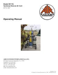
Your compressor is fitted with a sight-glasswhich allows you to check the oil level at anytime. When the compressor is running theoil level will fall but should not be lower thanhalf full in the sight-glass. If oil is low, stopthe compressor and fill to correct level.ABCDOIL CHANGE PROCEDURE1. Ensure there is no pressure in compressor body or receiver, gauges must be at zero.2. Remove filler plug/dipstick (A) and gasket, replace if necessary (B).3. Carefully remove drain plug (D) and gasket, replace if necessary (C).4. Drain oil (.8 liter) into suitable container positioned under compressor. Note: Any waste oil collected must bedisposed of in an approved manner.5. Refit drain plug (D) with gasket (C). Tighten to 20 Nm (14.75 ft/lbs).6. Fill compressor with only factory approved oil - part no. HP-268 (approximately .8 liters).7. Oil should just reach the bottom of the threads when the filler plug/dipstick (A) and the gasket (B) are fitted.8. Refit filler plug (A) using the gasket. (8). Tighten to 25 Nm (18.5 ft/lbs).9. Run compressor for 10 seconds then recheck oil level.10. Top off oil level, if necessary, following the above procedure. DO NOT OVERFILL COMPRESSOR!OIL COOLERBlow dust off oil cooler periodically.Page 5 Revision 2 January 2001
REMOVAL OF AIR IN<strong>TA</strong>KE FILTERThe air filter is located beneath the filter cover (A). Disconnect pipe (B).WARNING: IF ANY AIR ESCAPES BEFORE OUTLET PIPE IS FULLY REMOVED, STOP! DO NOT REMOVEUNTIL ALL PRESSURE IS LOST.1. Firmly pull cowl (A) to remove from air end.2. Unclip air filter (D) from the retaining clip (F) and discard air filter.Note: <strong>Air</strong> filter may contain traces of oil and must be disposed of in an approved manner.3. Unclip air filter support (E) and clean separator casing and inside of cowl.REPLACING THE OIL SEPARATOR ELEMENT1. Remove cap head screws (G).2. Gently tap the end cover (H) until it is clear of the separator casing.3. Unscrew the oil separator element (J) and discard4. Fit a new separator element (Model COMPA022). Ensure that the “O” ring (K) is in place. Do not overtighten.5. Refit end cover (H). Ensure cover is positioned correctly and bolt holes are in line. Be careful not to damage“O” ring (L) when refitting.6. Refit cap head screws (G). Tighten between 4 - 6.8 Nm (3 - 5 ft/lbs).REPLACEMENT OF AIR IN<strong>TA</strong>KE FILTER1. Reinstall air filter support (E). Fit a new air filter (D) and secure both ends using the retaining clip (F).2. Refit cowl (A).3. Reconnect pipe (B) and tighten securely.<strong>Air</strong> Filter LocationSeparator Element LocationRevision 2 January 2001Page 6
SERVICE SCHEDULEDaily1. Check Oil Level2. Drain <strong>Air</strong> Receiver Tank, If UsedEvery 50 Hours1. Check Oil Level2. Clean Or Replace <strong>Air</strong> Intake Filer3. Clean Oil CoolerEvery 500 Hours1. Clean Oil Cooler2. Change Oil3. Change <strong>Air</strong> Intake filter4. Change Oil SeparatorORDERING INFORMATIONItem NumberHP-268-1HP-268-5COMPA022COMPA028COMPA023COMPA021COMPA041COMPA 043DescriptionUSDA Approved Oil-1 gallonUSDA Approved Oil-5 gallonOil Separator"O" Ring Oil Separator (front)"O" Ring Oil Separator (rear)Intake <strong>Air</strong> FilterOil Fill Plug GasketOil Drain Plug Gasket<strong>TA</strong>-3 & <strong>TA</strong>-3EA COMPLETEASSEMBLYREGULATORY ASSEMBLY(Included with <strong>TA</strong>-3EA ONLY!)ITEM # DESCRIPTION PART #1 OUTLET FITTING QDH5SL8M2 RELIEF VALVE, 150 PSI VR4150BR3 ON/OFF SWITCH ELSW0214 PNEUMATIC TIRE ELCB0085 POWER CORD, 12-3 HDW R1086 RESERVE AIR CONNECTION QDH3SL4MDC7 BOTTLE PRESSURE GAUGE GA2075KB8 REGULATOR REG0079 CGA-347 STEM HPBR04910 CGA-347 NUT HPBR05011 RELIEF VALVE, 125 PSI VR4125BR12 OUTLET PRESSURE GAUGE GA20160BUNPage 7 Revision 2 January 2001
ANTES DE LA PUES<strong>TA</strong> EN MARCHA INICIAL, ASEGURARSE QUE LA CÁMARA DE ACEITE DEL COMPRESORESTÉ LLENA AL NIVEL CORRECTO CON ACEITE APROBADO PARASISTEMAS SE AIRE.Descripción GeneralEl <strong>TA</strong>-3 es un compresor de aire para respirar de 3 hombres portÜtil diseñado exclusivamente para usarse conrespiadores que demandan presión hasta 110 lbs/plug (75 bar) que se supervisa por un manómetro integral. Nota:El <strong>TA</strong>-3 tiene que tener una unidad de filtración de Grado D conectada al compresor para así tener un paquetede respiración de aire completo. Cualquier cilindro de aire de 30 ó 60 minutos puede deslizarse en el armazón del<strong>TA</strong>-3 e incluyendo un regulador reductor de presión y un Auto-<strong>Air</strong> Breather Box , ahora tiene un compresor de 3hombres con respaldo de aire totalmente automÜtico para una operación IDLH (Modelo COMP-3EA). El compresordebería estar conectado a la unidad de filtración con una manguera de aire de respirar con un diÜmetro interiormínimo de 0.5 de pulgada. ¡ LOS RESPIRADORES DE FLUJO CONS<strong>TA</strong>NTE NO PUEDEN USARSE CON ESTESISTEMA!Nota: Simpre operar, almacenar or embarcar el compresor en su posición horizontal.Nunca colocar la unidad verticalmente, ya que el aceite se evacua delsumidero y Causa daños al compresor. Verificar el nivel de aceite delcompresor antes de de cada uso. Se requiere una llave de 7/8" para aflojar lajuerca del sumidero aceite. El aceite debería estar parejo con el de las roscasinternas. NO SOBRELLENAR. Si el nival de aciete estÜ bajo, añadir aceiteaprobado por <strong>Air</strong> <strong>Systems</strong> solamente. Ordenar lubricante sintético No. DeParte HP-268.Procedimento De PreparaciónModelo <strong>TA</strong>-3 (Sistema COMP-3)Advertencia: Siempre colocar el compresor en un ambiente de aire fresco aparte de polvos, vapores yhumos tóxicos.PASO 5)Ajustar el regulador en la unidad de filtració de Grado-Da la presión de salida requerida (psi) del respirador de demandade presión. Estudiar el manual de la unidad de filtración Grado-Dy del monitor de monóxido de carbono para obtener detalles de laoperación, servicio, y calibración antes de comenzar el trabajo.Conectar y poner el respirado.PASO 1)El compresor debe estarconectado a una unidad defiltració de Grado-D. Unamanguera con un díametrointerior mínimo de ½” tieneque usarse entre elcompresor y la unidad defiltración Grado-D.PASO 4)Conectar la manguera de abastecimientode respirador a accesorios de salida en launidad de filtración de Grado-D. Nuncadejar un respirador abierto (sin usar)conectado al sistema, ya que la presiónde salida no se mantendrÜ.PASO 3)Activar el compresor ynotar la lectura demanómetro en elcompresor. Permitir que sellenen los receptoresgamelos de aire a lapresión del sistema de unasalida de 110psi (75 bar.)PASO 2)Enchufar el compresor en un tomacorriente de 115 voltios con unservicio didicado de 20 amperios. Nota: Si se usa un cordón eléctrico deentensión, dicho cordón debe estar diseñado para un servicio míminode 20 amperios (calibre 12/3).Nota: No sustitir elacomplamiento proporcionadoen la salida del tanque delcompresor, excepto con unacomplamiento estilo tope deun mínimo de diÜmetro interiorde ½”. No usar uncomplamiento estilo Chicagoen este tipo de compresor.Revision 2 January 2001Page 8
Su compresor estÜ equipado con un vidriode nivel, el cual le permite verificar elnivel de aceite en cualquier momento.Cuando el compresor estÜ operando, elnivel de aceite bajarÜ, pero no deberíaestar por debajo de la mitad en el vidrio denivel. Si el aceite estÜ bajo, parar elcompresor y llenarlo al nivel correcto.PROCEDIMIENTO DE CAMBIO DE ACEITE1. Asegurarse que no hay presión en el cuerpo o recipiente del compresor, los manómetros tienen que leercero.2. Retirar tapón de llenado/varilla de nivel (A) y desechar sello pegado (B)3. Retirar cuidadocamente el tapón de dreaje (D) y desechar sello pagado (C).4. Drenar el aceite (.8 litro) en un recipiente adecuado colocado debajo del compresor. Nota: Cualquier aceitede desecho acummulado se tiene que desechar de una manera aprobado.5. Colocar nuevamente el tapón de drenajo (D) con un nuevo sello pegado (C). Apretar a un torque de 20 Nm(14.75 pies/lbs).6. Llenar el compresor de aceite aprobado por la fÜbrica solamentenúmero de parte HP-268 (aproximadamente.8 litro).7. El aceite debería llegar hasta el fondo de las roscas cuando el tapón de llenado/varilla de nivel (A) y el sello(B) estÜn instalados.8. Instalar nuevamente el tapón de llenado (A) usando un nuevo sello pegado (B). Apretar a un torque de25Nm (18.5 pies/lbs).9. Operar el compresor por 10 segundos, entonces verificar nuevamente el nivel de aceite.10. Rematar el nivel de aceite, si es necesario, siguiendo el procedimiento anterior. ¡ NO SOBRELLENAR ELCOMPRESOR!ENFRIADOR DE ACEITESoplar el polvo del enfriadorde aceite periodicamente.Revision 2 January 2001Page 10
REMONCIÓN DEL FILTRO DE ADMISIÓN DE AIREEl filtro de aire estÜ situado detrÜs de la cubierta del filtro (A). Desconectar la tubería (B).ADVERTENCIA: SI CUALQUIER AIRE SE FUGA ANTES QUE LA TUBERÍA DE SALIDA ESTÉTO<strong>TA</strong>LMENTE RETIRADA, ¡ PARADA ! NO RETIRAR HAS<strong>TA</strong> QUE SE CAIGA TODA LA PRESIÓN.1. Tirar de la capucha (A) firmemente para retirarla del extremo del aire.2. Desconectar el filtro de aire (D) de la grapa de retención (F) y desechar el filtro de aire.Nota: Es posible que cualquier filtro de aire contenga trazas de aceite y se deben eliminar deuna manera aprobada.3. Desconectar el soporte del filtro de aire (E) y limpiar la carcasa del separador y la parte interior de la capucha.CÓMO RETIRAR EL ELEMENTO SEPARADOR DE ACEITE1. Retirar los tornillos de mÜquina (G).2. Golpear suavemente la cubierta de extremo (H) hasta que esté fuera de la carcasa del separador.3. Desenroscar el elemento sparador de aceite (J) y desecharlo.4. Colocar un elemento separador nuevo (Modelo COMPA022). Asegurarse que el anillo “O” (K) estÜ en selugar. No apretar demasiado.5. Colocar nuevamente la cubierta de extremo (H). Asegugar que la cubierta estÜ colocada correctamente ylos agujeros de los tornillos estén alineados. Tener cuidado no dañar los anillos “O” (L) cuando se estéinstalado nuevamente.6. Colocar nuevamente los tornillos de mÜquina (G). Apretar a un torque entre 4-6.8 Nm (3-5 pies/lbs.).SUSTITUCIÓN DEL FILTRO DE ADMISIÓN DE AIRE1. Instalar nuevamente el soporte del filtro de aire (E). Colocar un filtro de aire nuevo (D) y asegurar ambosextremos usando la grapa de retención (F).2. Colocar nuevamente la capucha (A).3. Conectar nuevamente la tubería (B) y apretar firmemente.Emplacement du filtre á airEmplacement de lélément séparateurPage 11 Revision 2 January 2001
PROGRAMA DE SERVICIODIARIO1. Verificar el nivel de aceite2. Drenar el receptor de aire, si se usaCADA 50 HORAS1. Verificar el nivel aceite2. Limpiar o sustituir el filtro de admisión de aire3. Limpiar el enfriador de aceite.CADA 500 HORAS1. Limpiar el enfriador aceite2. Cambiar el aceite3. Cambiar el filtro de admisión de aire4. Cambiar el separador de aceiteINFORMACIÓN PARA ORDENARNúmero de ítemHP-268-1HP-268-5COMPA022COMPA028COMPA023COMPA021COMPA041COMPA043Descripcíon1 galón de aceite aprobado por USDA5 galones aceite aprobado por USDASeparador de aceiteAnillo de “O” de separador de aceite (Frontal)Anillo de “O” de separador de aceite (Posterior)Filtro de admisión de aireEmpaquetadura de tapón de llenado de aceiteEmpaquetadura de tapón de drenaje de aceiteENSEMBLE COMPLETO DE <strong>TA</strong>-3 Y <strong>TA</strong>-3EA¡Ensamble de regulador includiocon <strong>TA</strong>-3EA solamente!ARTÍCULO Nº DESCRIPCIÓN Nº DE PARTE1 ACCESSORIO DE SALIDA QDH5SL8M2 VÁLVULA DE ALIVIO, 125 lbs/plug² VR4125BR3INTERRUPTOR DE ON/OFF(ACTIVADO/DESACTIVADO)ELSW0214 RUEDA NEUMÁTICA HDWR1085 CORDÓN ELÉCTRICA, 12-3 ELCB0026 CONEXIÓN DE AIRE DE RESERVA QDH3SL4MDC7 MANÓMETRO DE RECIPIENTE GA2075KB8 REGULADOR REG0079 VÁS<strong>TA</strong>GO CGA-347 HPBR04910 TUERCA CGA-347 HPBR05011 VÁLVULA DE ALIVIO, 125 lbs/plug² VR4125BR12 MANÓMETRO DE SALIDA GA201060BUNRevision 2 January 2001Page 12
RETRAIT du FILTRE DADMISSION DAIRLe filtre à air se situe en dessous du cache-filtre (A). Dégagez la conduite (B).ADVERTISSEMENT : SI DE LAIR SECHAPPE AVANT DE RETIRER COMPLETEMENT LA CONDUITE DESORTIE, ARRETEZ TOUTE ACTIVITE ! NE LA RETIREZ-PAS <strong>TA</strong>NT QUE TOUT LA PRESSION NEST PASEVACUEE COMPLETEMENT.1. Retirez fermement le capor protection (A) pour le dégager de lextrémité du tuyau dair.2. Détachez le filtre à air (D) du crochet de fixation (F) et retirez le filtre à air.Remarque : Le filtre à air risque de contenir des traces dhuile et doit être éliminée conformément auxnormes de sécurité.3. Détachez le support de filtre à air (E) et nettoyez le boîtier du séparateur et lintérieur du capot de protection.REMPLACEMENT de LELEMENT SEPARATEUR DHUILE1. Retirez les vis à tête (G).2. Donnez des petits coups sur couvercle du fond (H) jusqu à ce quil se sépare du boîtier du séparateur.3. Dévissez l élément séparateur dhuile (J) et retirez-le.4. Montez un nouvel élément séparateur (Modèle COMPA022). Vérifiez que le joint torique (K) est fixéfermement. Attention à lexcés de serrage.5. Remettez le couvercle du fond (H). Assurez-vous que le couvercle est mis en place correctement et que lestrous des boulons sont alignés. Veillez à ne pas endommager le joint torique (L) lorsque de la fixation.6. Revissez les vis à tête (G). Serrez selon une tension comprise entre 4 et 6,8 nm (3 et 5 pieds/livres).REMPLACEMENT du FILTRE DADMISSION de LAIR1. Remontez le support de filtre à air (E). Emboîtez un nouveau filtre à air (D) en attachez les deux extrémitiés àlaide du crochet de fixation (F).2. Remontez le capor de protection (A).3. Reconnectez la conduite (B) et serrez-la fermement.Emplacement du Filtre à airEmplacement de lélément séparateurRevision 2 January 2001Page 16
PROGRAMME DENTRETIENJournalier1. Vérification du niveau dhuile2. Vindage du réservoir de récupération de lair, si utiliséToutes les 50 heures1. Vérification de niveau dhuile2. Nettoyage ou remplacement du filtre dadmission dair3. Nettoyage du refroidisseur dhuileToutes les 500 heures1. Nettoyage de refroidisseur dhuile2. Vindage dhuile3. Remplacement du filtre dadmission dair4. Remplacement du séparateur dhuleINFORMATIONS RELATIVES AUC COMMANDESNuméro darticleHP-268-1HP-268-5COMPA022COMPA023COMPA021COMPA041COMPA043DescriptionHuile approuvée par lUSDA1gallonHuile approuvée par lUSDA5 gallonsSéparateur dhuileJoint torque du séparateur dhuile (devant)Filtre dadmission dairJoint détanchéité du bouchon du remplissage dhuileJoing détanchéité du bouchon du vindage dhuileMON<strong>TA</strong>GE COMPLET de <strong>TA</strong>-3 ET <strong>TA</strong>-3EAMontage du régulateur inclusavec <strong>TA</strong>-3EA uniquement !ITEM # DESCRIPTION PART #1 RACCORD DE SORTIE QDH5SL8M2SOUPAPE DE DÉCHARGE125PSIVR4125BR3 ON/OFF SWITCH ELSW0214 PNEU PNEUMATIQUE HDWR1085CORDON D’ALIMEN<strong>TA</strong>TION12-3ELCB0026RACCORDEMENT D’AIR DERÉSERVEQDH3SL4MDC7MANOMÉTRE DUCYLINDREGA2075KB8 RÉGULATEUR REG0079 TIGE CGA-347 HPBR04910 ÉCROU CGA-347 HPBR05011SOUPAPE DE DÉCHARGE,125 PSIVR4125BR12 MANOMÉTRE DE SORTIE GA20160BUNPage 17 Revision 2 January 2001
Warranty Disclaimer<strong>Air</strong> <strong>Systems</strong> manufactured equipment is warranted to the original user against defects in workmanship or materials undernormal use for one year after date of purchase. Any part of which is determined by <strong>Air</strong> <strong>Systems</strong> to be defective in material orworkmanship will be, as the exclusive remedy, repaired or replaced at <strong>Air</strong> <strong>Systems</strong> option. This warranty does not apply toelectrical systems or electronic components. Electrical parts are warranted, to the original user, for 90 days from the date ofsale. During the warranty period, electrical components will be repaired or replaced at <strong>Air</strong> <strong>Systems</strong> option.NO OTHER WARRANTY, EXPRESSED OR IMPLIED, AS TO DESCRIPTION, QUALITY, MERCHANT ABILITY,FITNESS FOR A PARTICULAR PURPOSE, OR ANY OTHER MATTER IS GIVEN BY AIR SYSTEMS IN CONNEC-TION HEREWITH. UNNDER NO CIRCUMS<strong>TA</strong>NCED SHALL THE SELLER BE LIABLE FOR LOSS OF PROFITS,AND OTHER DIRECT OR INDIRECT COSTS, EXPENSES, LOSSES OR DAMAGES, ARISING OUT OF DEFECTSIN, OR FAILURE OF THE PRODUCT OR ANY PART THEROF.The purchaser shall be solely responsible for compliance with all applicable Federal, State, and Local OSHA and/or MSHArequirements. Although <strong>Air</strong> <strong>Systems</strong> <strong>International</strong> believes that its products, if operated and maintained as shipped from thefactory and in accordance with our “operations manual”, conform to OSHA and/or MSHA requirements, there are no impliedor expressed warranties of such compliance extending beyond the limited warranty described herein. Product designs andspecifications are subject to change without notice. Rev 2 12/98Denegación de la garantíaEl equipo fabricado por <strong>Air</strong> <strong>Systems</strong> extiende garantía al usuario original contra defectos de mano de obra o demateriales durante el uso normal por un año después de la fecha de compra. <strong>Air</strong> <strong>Systems</strong> repara o reemplazacualquier parte que determine <strong>Air</strong> <strong>Systems</strong> que sura de defectos en cuanto a materials o a mano de obra, del modo queellos seleccionen como el remedio exclusivo. Esta grantía no aplica a sistems eléctricos o a componenteselectrónics. Se ofrece una garantía, <strong>Air</strong> <strong>Systems</strong> reparará los componentes electrónicos a su discreción.AIR SYSTEMS NO DA NINGUNA OTRA GARANTåA, EXPRESA O IMPLåCI<strong>TA</strong>, EN CUANTO A LADESCRIPCIÓN, CALIDAD, COMERCIABILIDAD, APLICACIÓN CORREC<strong>TA</strong> PARA UN MOTIVOESPECåFICO, O CUALQUIER OTRO TEMA EN CONEXIÓN CON ESTE DOCUMENTO. BAJO NINGUNACIRCUNS<strong>TA</strong>NCIA SERÁ RESPONSABLE EL VENDEDOR EN CUANTO A PÉRDIDA DE INGRESOS,CUALQUIER OTRO COSTO, GASTO, PÉRIDIDA O DAÑO DIRECTO O INDIRECTO QUE OCURRACOMO RESUL<strong>TA</strong>DO DE DEFECTOS EN EL PRODUCTO O EN EL FALLO DEL PRODUCTO OCUALQUIER PARTE DEL MISMO.El comprador será unicamente responsable por cumplir con todos los requisitos vigentes federales, estatales o localesde OSHA y/ o de MSHA. Aunque <strong>Air</strong> <strong>Systems</strong> <strong>International</strong> cree que sus productos cumplen con los requisitos deOSHA y/o MSHA, si se operan y se mantienen como fueron embarcados de la fábrica según nuestro “manual deoperación”, no extendemos garantías implícitas o expresadas de dicho cumplimiento fuera de la garantía limitadadescrita en este documento. Los diseños y las especificaciones de los productoes están sujetos a cambios sinnotificación previa. Revisión 2 12/98Limitations de la garantieLes produits manufacturés par <strong>Air</strong> <strong>Systems</strong> comportent, pour le premier acheteur, une garantie contre tout vice defabrication ou défaut de matériau, à condition d’être utilisés comme prévu, et ce pour une durée d’un an à compter dela date d’achat. Si <strong>Air</strong> <strong>Systems</strong> estime qu’un composant présente un vice de fabrication ou un défaut de matériau, cecomposant sera réparé ou remplacé à sa discrDenegación de la garantíaétion, et cela constituera le seul recours possible. Cette garantie ne s’applique pas aux ensembles électriques ni auxéléments électroniques. Les pièces électriques sont couvertes par une garantie de 90 jours à compter de la dated’achat, et ce uniquement pour le premier acheteur. Durant la période de garantie, les composants électriques serontréparés ou remplacés à la discrétion d’<strong>Air</strong> <strong>Systems</strong>.AIR SYSTEMS N’OFFRE AUCUNE AUTRE GARANTIE, EXPRESSE OU <strong>TA</strong>CITE, QUANT À LA DESCRIP-TION, LA QUALITÉ, LA VALEUR MARCHANDE, LA CONVENANCE À UN USAGE PARTICULIER, OUTOUTE AUTRE FONCTION LIÉE AU PRODUIT CI-JOINT. LE VENDEUR NE POURRA EN AUCUN CASÉTRE TENU RESPONSABLE DES PERTES DE <strong>REV</strong>ENUS NI DES AUTRES COUTS DIRECTS OU INDIRECTS,NI ENCORE DES DÉPENSES, PERTES OU DOMMAGES ENCOURUS EN RAISON DU VICE DE FABRICA-TION DU PRODUIT OU DE LA DÉFAILLANCE MÉCANIQUE DE CE DERNIER, OU ENCORE DE TOUTEPIÈCE DONT IL EST CONSTITUÉ.Il incombe entièrement à l’acheteur de se conformer aux directives des organismes réglementaires en vigueur auniveau fédéral, provincial ou municipal. <strong>Air</strong> <strong>Systems</strong> <strong>International</strong> estime que ses produits respectent les normes del’OSHA et de MSHA dans la mesure où ses produits sont utilisés et entretenus selon l’état dans lequel ils se trouvaient àleur sortie d’usine, et en conformité avec le manuel d’utilisation. Aucune garantie tacite ou expresse n’est exprimée, sice n’est celle qui est contenue dans les présentes. Les modèles ou données techniques peuvent être modifiés sanspréavis. Révision 2 12/98Revision 2 January 2001Page 18