CO91-14LAC REV 3 - Air Systems International
CO91-14LAC REV 3 - Air Systems International
CO91-14LAC REV 3 - Air Systems International

Create successful ePaper yourself
Turn your PDF publications into a flip-book with our unique Google optimized e-Paper software.
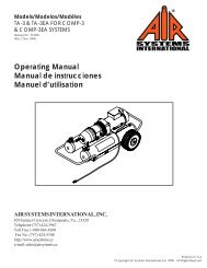
Manual No. MON006<br />
Rev. 5 April 2013<br />
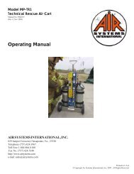
OPERATING MANUAL<br />
MODEL: <strong>CO91</strong>-<strong>14LAC</strong><br />
<strong>Air</strong> <strong>Systems</strong> <strong>International</strong>, Inc.<br />
829 Juniper Crescent, Chesapeake, Va, 23320<br />
Telephone (757) 424-3967<br />
Toll Free 1-800-866-8100<br />
Fax No. (757) 424-5348<br />
http://www.airsystems.com<br />
e-mail: sales@airsystems.com
2<br />
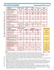
cArBon monoXiDe monitor oVerVieW<br />
The monitor will analyze the air sample and display the CO concentration in parts per million (ppm). The<br />
system’s green “NORMAL” operation light will illuminate and the red “HIGH CO” light will flicker approximately<br />
every second when the CO level is below 10ppm (5ppm Canadian). If the CO concentration level exceeds the<br />
alarm set point, the green “NORMAL” light will turn off, the red “HIGH CO” light will illuminate, the audible<br />
alarm will sound, and the remote alarm connections will energize. Once the CO concentration levels drop below<br />
the alarm set point, all alarm indicators will deactivate and the unit will return to “NORMAL” operation.<br />
MONITOR SPECIFICATIONS<br />
Size<br />
2.75”H X 6.57”L X 5.1”W<br />
Test Circuit<br />
Manually activated<br />
Weight<br />
Case<br />
Voltage<br />
Shielding<br />
Fuse<br />
Operating<br />
Temperature<br />
2.8 lBS. (1.27kg.)<br />
Extruded Aluminum - anodized black<br />
115 VAC and/or 9-16 VDC<br />
Internal RFI/EMI filters<br />
115 VAC/1 amp fast acting<br />
4° to 113° Fahrenheit<br />
(-15.5° to 45° Celcius)<br />
Sensor Type<br />
Accuracy<br />
Response<br />
Detectable<br />
Range<br />
Calibration<br />
Sealed electrochemical sensor for<br />
Carbon Monoxide<br />
+/-1% full scale<br />
90% in 10-15 seconds<br />
0-200 ppm CO<br />
Manual CO zero and span adjustments<br />
Humidity<br />
Range<br />
Flow<br />
Requirement<br />
Display<br />
10% to 90% relative humidity<br />
50 - 100 cc/min<br />
3 digit LCD<br />
CO concentration<br />
Alarm Setting<br />
Warning<br />
Signals<br />
Warranty<br />
10 ppm CO (5 ppm - Canadian)<br />
Normal operation - Green Light<br />
High CO - Red Light<br />
High CO - Audible Alarm<br />
Low Battery - Amber Light<br />
2 years from original date of purchase<br />
REPLACEMENT PARTS<br />
ITEM # DESCRIPTION PART #<br />
1 CARBON MONOXIDE MONITOR CO-91<br />
2 AUDIBLE ALARM ELLS004<br />
3 RED LED MONC004<br />
4 CLEAR LENS ELDS013<br />
5 REMOTE ALARM JACK ELJP004<br />
6 REMOTE ALARM JACK COVER ELJP005<br />
7 GREEN LED MONC005<br />
8 PLUG MONC002<br />
9 HOSE CLAMP HOS056<br />
10 AIR SAMPLE HOSE (PER FOOT) HOS004<br />
11 HANSEN 3000 SERIES PLUG QDH3PL2M<br />
12 AIR SAMPLE SOCKET QDCSL4M<br />
13 1/4” STREET TEE BR4TS<br />
14 120 VAC RECESSED PLUG ELJP006<br />
15 AIR SAMPLE INLET QDCSL4M<br />
16 FLOWMETER WL033NS<br />
17 PRESSURE GAUGE GA1560S<br />
18 PRESSURE REGULATOR WL013A<br />
19 RELIEF VALVE VR2125BR
3<br />
setup/operation<br />
Step 1)<br />
Secure a low pressure Grade-D air source, under 150 PSI.<br />
Step 2)<br />
Attach sample hose to the air sample inlet located on the right side of the<br />
case and to the air source, 125 PSI max.<br />
Note: A sample hose is provided with two fittings so that a set up for<br />
a standard 1/4” fitting or a retrofit for an ambient air pump can be<br />
achieved. For an air pump set up, remove the pressure gauge and install a<br />
street tee in to the gauge port. Screw the socket into the street tee; this is<br />
the connection port for the monitor. Install the quick connect plug on the<br />
sample hose and secure with the clamp provided.<br />
See page 4.<br />
AIR SAMPLE INLET<br />
LOCATED ON RIGHT<br />
SIDE OF CASE<br />
1/4” INDUSTRIAL<br />
INTERCHANGE PLUG<br />
RETRO-FIT KIT FOR<br />
AMBIENT AIR PUMP<br />
Step 3)<br />
Adjust the regulator pressure to a maximum reading of 20 PSI.<br />
Step 4)<br />
Adjust the flowmeter so the ball hovers between 50 and 100 cc/min.<br />
Step 5)<br />
Place the “ON/OFF/TEST” switch to the “ON” position. Allow 30 seconds<br />
for the readout to stabilize. If a reading other than “ZERO” is displayed,<br />
calibration of the monitor may be necessary. If the CO concentration level<br />
exceeds the alarm set point, the green “NORMAL” light will turn off, the<br />
red “HIGH CO” light will illuminate, the audible alarm will sound, and the<br />
remote alarm connections will energize. Once the CO concentration level<br />
drops below the alarm set point, all alarm indicators will deactivate and<br />
the unit will return to “NORMAL” operation.
4<br />
UNIVERSAL AIR PUMP ADAPTER KIT FOR <strong>CO91</strong>-<strong>14LAC</strong><br />
STEP 1<br />
Remove existing gauge from bushing.<br />
STEP 2<br />
Install street tee in bushing. Install colder socket and<br />
gauge in street tee as shown.<br />
STEP 3<br />
Slide hose clamp over end of hose. Slide colder plug<br />
onto hose and crimp hose clamp over colder plug.<br />
ADAPTER HOSE FROM L.P. AIR SOURCE TO <strong>CO91</strong>-<strong>14LAC</strong><br />
STEP 1<br />
Slide hose clamp over end of hose. Slide<br />
1/2” plug onto hose and crimp hose clamp over hose<br />
barb.<br />
STEP 2<br />
Install 1/4” plug on Breather Box TM or other air source<br />
to be tested. Maximum pressure 125 PSI.
cAUtion: Always depressurize the 5 system before performing service.<br />
Filter Housing/Bowls: Periodic cleaning of the polycarbonate bowls may become necessary. Remove the auto<br />
drains and clean the bowls with a mild soapy solution. The auto drains may also be cleaned with a mild soapy<br />
solution at this time. Dry and reinstall into the filter housing.<br />
Filter Change: The filtration system consists of filter change indicators which will gradually change from green to<br />
orange when filter life is spent.<br />
Note: <strong>Air</strong> must be flowing through the filters before the filter change indicators will function.<br />
With system pressurized, close inlet ond outlet ball valves. Release the filter trio pressure by pressing the manual<br />
drain assembly to the side. Remove the SYSTEM bowl assemblies MAINTENANCE<br />
by releasing the lock ring.<br />
Calibration: Monitor calibration should be done monthly or whenever the reading may be questionable. A calibration<br />
date sticker should be affixed for future reference. To obtain an accurate calibration, we recommend the<br />
use of <strong>Air</strong> <strong>Systems</strong> calibration kits.<br />
Part Number:<br />
BBK-10 Canadian calibration kit for CO monitor; 10ppm CO, zero air, regulator and case - 17 liter size.<br />
BBK-20<br />
Calibration kit for CO monitor; 20ppm CO, zero air, regulator and case - 17 liter size.<br />
BBK-20103 Calibration kit for CO monitor; 20ppm CO, zero air, regulator and case - 103 liter size.<br />
DECAL085 Calibration decal, sold in sheet of 14.<br />
To assure sensor accuracy, calibration of monitor is required. If you cannot obtain an accurate calibration, sensor<br />
replacement may be necessary. Consult Repair Service Department before ordering.<br />
Part Number:<br />
CO-91NS Replacement CO sensor<br />
monitor BAttery rePlAcement<br />
These batteries provide the required continuous bias voltage to the CO sensor and power the monitor in the<br />
event of AC power loss. If AC and DC power are removed for a period of 2 hours or more, a 1 hour restabilization<br />
period is required on the sensor as eratic readings may occur.<br />
Battery Replacement: Replace 9 volt batteries when the amber “Low Battery” light illuminates. If the monitor<br />
is not used for 90 days, check the 9 volt batteries and replace if necessary.
6<br />
CO MONITOR PARTS BREAKDOWN
7<br />
CO MONITOR PARTS BREAKDOWN<br />
ITEM # DESCRIPTION PART #<br />
1 LCD Display MONC703<br />
2 Span Potentiometer MONC702A<br />
3 Alarm Set Point Potentiometer MONC702A<br />
4 Zero Potentiometer MONC702<br />
5 <strong>Air</strong> Sample Inlet Socket MONC001<br />
6 <strong>Air</strong> Sample Plug MONC002<br />
7 <strong>Air</strong> Exhaust Port MONC003<br />
8 On/Off/Test Switch MONC007<br />
9 Recessed Plug With Fuse Holder MONC020<br />
10 1 Amp Fast Acting Fuse, 5 X 20Mm ELF001<br />
11 15 Pin Socket MONC520<br />
12 Faceplate/Endplate Screw MONC023<br />
13 Main Circuit Board Assembly CO-91PCB<br />
14 Power Supply Board CO-91PSB<br />
15 Sensor Connector (Soldered To PCB) MONC509<br />
16 Battery Box MONC006<br />
17 9 Volt Battery ELB9V<br />
18 Calibration Tool MONC028<br />
19 End Plate CO-91BEP<br />
20 Aluminum Housing CO-91HOU<br />
21 Led Socket MONC009LA<br />
22 Yellow Led MONC008NS<br />
23 Led Socket And Yellow Led CO-91LED<br />
24 PPM/Serial No. Sticker MONC031<br />
25 Battery Box Connector (Soldered To PCB) MONC516<br />
26 Led Connector (Soldered To PCB) MONC511<br />
27 12 VDC Power Socket MONC522<br />
28 12 Volt Power Plug (Optional) ELJP018<br />
29 12 Volt Cable (Order By The Foot) ELCB035<br />
30 CO Sensor CO-91NS<br />
31 CO Sensor Holder MONC810<br />
32 CO Sensor Electrical Leads CO-91SL<br />
33 90° Hose Barb MONC811
SenSor rePlAcement<br />
Replacement sensors are shipped with a metal spring installed between the electrodes. Do not remove the<br />
clip until the sensor is to be installed into the monitor.<br />
8<br />
SteP 1)<br />
Disconnect all external connections.<br />
Remove CO monitor from the unit.<br />
SteP 2)<br />
Remove the four screws from the<br />
monitor’s left endplate.<br />
SteP 3)<br />
Remove endplate to gain access to<br />
the sensor cup.<br />
UNUSED<br />
CONTROL<br />
(BLACK)<br />
SENSING<br />
(RED)<br />
REFERENCE<br />
(BLUE)<br />
SteP 4)<br />
Remove sensor from sensor cup and remove leads. Take the<br />
new sensor and remove the metal spring. Reattach leads to<br />
the proper colored terminals on the new sensor. Install new<br />
sensor into sensor cup.<br />
SteP 5)<br />
Reassemble monitor and reinstall in<br />
unit. Connect all cables and air sample<br />
hose. Allow monitor to stabilize<br />
30 minutes to 1 hour and recalibrate.
9<br />
cAliBrAtion ProceDUre<br />
Do not use inert gases to zero the monitor. This will cause premature failure of the sensor.<br />
CO Monitor Zero Adjustment<br />
To zero the monitor, follow the steps below. Zero calibration gas should be used to properly “zero” the<br />
monitor and assure that a valid calibration is achieved. If zero adjustment cannot be made as indicated, sensor<br />
replacement may be necessary. After each monitor adjustment outlined in the steps, allow time for the<br />
changes to stabilize.<br />
SteP 1)<br />
Place the “ON/OFF/TEST” switch in the “ON” position.<br />
SteP 2)<br />
Allow 30 seconds for the readout to stabilize. The<br />
green indicator will illuminate.<br />
SteP 6)<br />
Turn the knob on the regulator counterclockwise to<br />
allow the flow of gas thru the hose. Verify flow of<br />
gas thru the hose via touch or sound.<br />
SteP 3)<br />
Hold the “ON/OFF/TEST” switch in the “TEST” position.<br />
The following will occur:<br />
Audible alarm will sound<br />
Green LED will flash<br />
Amber Low Battery indicator on monitor will<br />
illuminate<br />
Red LED will be on<br />
This test ensures the circuitry is operable and continuity<br />
to the sensor is proper. Release the switch.<br />
SteP 7)<br />
Attach the clear tubing with the male plug to the air<br />
sample inlet on the monitor.<br />
SteP 4)<br />
Remove the air sample inlet tube.<br />
SteP 8)<br />
Allow digital readout to stabilize approximately 15-<br />
30 seconds.<br />
SteP 5)<br />
Install regulator on the zero air cylinder reference<br />
gas.<br />
SteP 9)<br />
Adjust the “zero” adjustment screw (clockwise to<br />
increase or counterclockwise to decrease) until a<br />
reading of “00” is obtained.<br />
SteP 10)<br />
Turn the regulator off and disconnect the regulatorfrom<br />
the zero gas cylinder.
10<br />
cAliBrAtion ProceDUre<br />
CO Monitor Span Adjustment<br />
Use only 10-20ppm CO gas for calibration. Using a higher concentration may decrease accuracy at<br />
lower scale readings. Note: 10ppm gas must be used to satisfy Canadian calibration requirements.<br />
SteP 1)<br />
Install regulator on the CO calibration gas cylinder.<br />
SteP 4)<br />
Allow digital readout to stabilize 15-30 seconds.<br />
SteP 5)<br />
Adjust the “span” adjustment screw (clockwise to<br />
increase or counterclockwise to decrease) until the<br />
digital readout reads the same as the concentration<br />
(ppm) as printed on the calibration gas cylinder.<br />
SteP 2)<br />
Turn the knob on the regulator counterclockwise to<br />
allow the flow of gas thru the hose. Verify flow of<br />
gas thru the hose via touch or sound.<br />
SteP 6)<br />
Turn the regulator off and repeat the “zero” adjustment<br />
procedure. The digital readout should return<br />
to a “00” reading.<br />
SteP 3)<br />
Connect the plug to the air sample inlet on the<br />
monitor.<br />
The monitor is now calibrated and should be<br />
recalibrated monthly or if accuracy is questionable.<br />
Check local requirements and recalibrate as<br />
required.
11<br />
WArrAnty DiSclAimer<br />
<strong>Air</strong> <strong>Systems</strong>’ manufactured equipment is warranted to the original user against defects in workmanship or materials<br />
under normal use for one year from the date of purchase. Any part which is determined by <strong>Air</strong> <strong>Systems</strong><br />
to be defective in material or workmanship will be, as the exclusive remedy, repaired or replaced at <strong>Air</strong> <strong>Systems</strong>’<br />
option. This warranty does not apply to electrical systems or electronic components. Electrical parts are<br />
warranted, to the original user, for 90 days from the date of sale. During the warranty period, electrical components<br />
will be repaired or replaced at <strong>Air</strong> <strong>Systems</strong>’ option.<br />
no otHer WArrAnty, eXPreSSeD or imPlieD, AS to DeScriPtion, QUAlity, mercHAntABility, FitneSS<br />
For A PArticUlAr PUrPoSe, or Any otHer mAtter iS GiVen By <strong>Air</strong> SyStemS in connection Here-<br />
WitH. UnDer no circUmStAnceS SHAll tHe Seller Be liABle For loSS oF ProFitS, Any otHer Direct<br />
or inDirect coStS, eXPenSeS, loSSeS, or DAmAGeS AriSinG oUt oF DeFectS in, or FAilUre oF tHe<br />
ProDUct or Any PArt tHereoF.<br />
The purchaser shall be solely responsible for compliance with all applicable Federal, State and Local OSHA and/<br />
or MSHA requirements. Although <strong>Air</strong> <strong>Systems</strong> <strong>International</strong> believes that its<br />
products, if operated and maintained as shipped from the factory and in accordance with our “operations<br />
manual”, conform to OSHA and/or MSHA requirements, there are no implied or expressed warranties of such<br />
compliance extending beyond the limited warranty described herein. Product designs and specifications are<br />
subject to change without notice. Rev. 2, 12/98<br />
<strong>Air</strong> leaks are not covered under warranty except when they result from a defective system component, i.e. an<br />
on/off valve or regulator or upon initial delivery due to poor workmanship. <strong>Air</strong> leaks due to poor delivery or<br />
damage will be covered under delivery claims. Minor air leaks are part of routine service and maintenance and<br />
are the responsibility of the customer just as are filters and oil changes.
<strong>Air</strong> SyStemS internAtionAl, inc.<br />
829 Juniper Crescent, Chesapeake, Va, 23320<br />
Telephone (757) 424-3967<br />
Toll Free 1-800-866-8100<br />
Fax No. (757) 424-5348<br />
http://www.airsystems.com<br />
e-mail: sales@airsystems.com<br />
Printed in the U.S.A. ©Copyright <strong>Air</strong> <strong>Systems</strong> <strong>International</strong>, Inc. 2012 All Rights Reserved