
Create successful ePaper yourself
Turn your PDF publications into a flip-book with our unique Google optimized e-Paper software.
02/2011
Este catálogo substitui todas as edições anteriores que perdem<br />
assim sua validade.<br />
Os dados técnicos contidos neste catálogo referem-se aos atualmente<br />
usados pela VULKAN DRIVE TECH.<br />
As alterações com base em avanços tecnológicos são reservadas.<br />
Em caso de dúvidas ou para obter esclarecimentos, consulte a VULKAN.<br />
Edição 02/2011<br />
Todos os direitos de cópia, reimpressão e traduções são reservados.<br />
Alterações dimensionais e construtivas são reservadas sem prévio aviso.<br />
02<br />
This catalogue replaces all prior issues which become thus invalid.<br />
The technical data contained in such catalogue refer to those<br />
currently used by VULKAN DRIVE TECH.<br />
Changes based on technological advances are reserved. In case of<br />
doubt or further clarifications please contact VULKAN.<br />
Issue 2011/02<br />
All rights of duplication, reprinting and translation are reserved.<br />
We reserve the right to modify dimensions and constructions<br />
without prior notice.
Índice<br />
Index<br />
Generalidades / Generalities.............................................................................................................................<br />
06<br />
Seleção Detalhada / Selection Procedure..................................,,...................................................................... 07<br />
Formas / Designs.............................................................................................................................................. 08<br />
Forma GE / Design GE....................................................................................................................................... 10<br />
Forma GG / Design GG....................................................................................................................................... 11<br />
Forma GH / Design GH....................................................................................................................................... 12<br />
Forma GLE / Design GLE.................................................................................................................................... 13<br />
Forma GLG / Design GLG.................................................................................................................................... 14<br />
Forma GLV / Design GLV..................................................................................................................................... 15<br />
Forma GEB / Design GEB................................................................................................................................... 16<br />
Forma GGB / Design GGB................................................................................................................................... 17<br />
Forma GETW / Design GETW.............................................................................................................................. 18<br />
Forma GETB / Design GETB............................................................................................................................... 19<br />
Desalinhamentos Admissíveis / Admissibles Misalignments............................................................................... 20<br />
.<br />
Troca de Elemento Elástico / Replacing the Elastic Element............................................................................... 21<br />
Tabela de Conversão de Unidades / Unit Conversion Tables............................................................................... 22<br />
03
Flexomax - G - 02/2011<br />
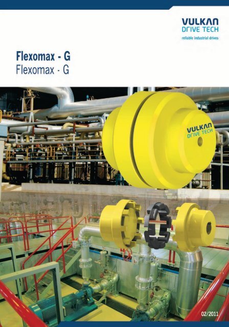
FLEXOMAX G<br />
Generalidades / Generalities<br />
O FLEXOMAX G é um acoplamento flexível e torcionalmente<br />
elástico. Sua flexibilidade permite juntar duas faces do eixo e<br />
acomodar desalinhamentos radiais, axiais e angulares que ocorrem<br />
em cada montagem. Devido as suas características elásticas este tipo<br />
de acoplamento absorve choques e vibrações provenientes da<br />
máquina acionada ou acionadora. Tem elemento elástico produzido<br />
com uma borracha especial, resistente à poeira, água, e óleo.<br />
Por sua construção simplificada, o FLEXOMAX G permite<br />
montagem rápida dispensando lubrificação e minimizando o<br />
tempo de manutenção. Em função de suas garras, este acoplamento<br />
é à prova de deslizamento rotativo.<br />
O FLEXOMAX G está disponível em 18 tamanhos e várias formas,<br />
com capacidade de torque máximo de 97.200 Nm e eixos de até 250<br />
mm de diâmetro.<br />
06<br />
Reservamo-nos o direito de alterações sem prévio aviso.<br />
The FLEXOMAX G is a flexible and torsionally elastic coupling. Its<br />
flexibility allows to join two shaft ends and accommodate axial,<br />
angular and radial misalignment that occur in every assembly. Due to<br />
the elastic characteristics this kind of coupling is able to absorb shocks<br />
and vibrations of the machine, either from the driving or driven side.<br />
The elastic element is made of a special rubber, resistant to dust, water<br />
and oil.<br />
As the FLEXOMAX G has a smart design, it allows a quickly mounting<br />
and does not need any lubrication, what minimizes the maintenance<br />
time. Due to its claws this coupling is considered as anti-rotative<br />
slipping.<br />
The FLEXOMAX G is available in 18 sizes, has several designs, a<br />
maximum torque capacity of 97.200 Nm and admits shaft diameters<br />
up to 250 mm.<br />
We reserve the right of technical alterations without previous notice.
FLEXOMAX G<br />
Seleção Detalhada / Selection Procedure<br />
Na seleção de um acoplamento é imprescindível considerar o To select the correct coupling it is necessary to take into account the<br />
torque da máquina acionadora e o grau de irregularidade do torque of the driving machine and the irregularity degree of the<br />
sistema, como também a magnitude das massas a serem aceleradas. system, as well as the magnitude of the masses to be accelerated. To<br />
Para a determinação do tamanho apropriado é necessário determine the appropriate size it is necessary to multiply the service<br />
considerar os fatores de serviço descritos abaixo, os quais<br />
multiplicados pelo torque nominal da máquina acionadora,<br />
determinarão o torque equivalente ( Meq). O torque nominal<br />
( Tkn) do acoplamento escolhido deverá ser maior ou igual ao<br />
torque equivalente.<br />
factors below by the nominal torque of the driving machine, which will<br />
appoint the equivalent torque (M eq). The nominal torque (T kn)<br />
of<br />
the selected coupling shall be higher or equal to the<br />
equivalent torque.<br />
C x N x Fs<br />
M eq =<br />
n<br />
M eq<br />
N<br />
n<br />
Fs<br />
= torque equivalente (Nm) / equivalent torque (Nm)<br />
= potência da máquina acionadora (kW/ HP) / driving machine (kW/ HP)<br />
= rotação de trabalho do acoplamento (rpm) / coupling working rotation (rpm)<br />
= F1 x F2 x F3 x F4 = fator de serviço / F1 x F2 x F3 x F4 = service factor<br />
T kn = torque nominal do acoplamento (Nm) / coupling nominal torque (Nm)<br />
C = Constante / Constant:<br />
9550 para potência em / for power in kW<br />
7030 para potência em / for power in HP<br />
Condição para selecionar acoplamento / For Selecting a Coupling:<br />
T kn Meq<br />
Máquina Acionada:/<br />
Driven Machine:<br />
a) Com serviço regular e reduzidas massas a acelerar:<br />
- Bombas centrífugas para líquidos, geradores elétricos, ventiladores com N/n ≤<br />
0,05, redutores de velocidade, eixos.<br />
g) Outros equipamentos<br />
Funcionamento<br />
Diário (horas)/<br />
Daily Service<br />
Life (hours)<br />
Fator - “F2”<br />
Factor - “F2”<br />
Temperatura<br />
Ambiente (ºc)/<br />
Ambient<br />
Temperature (ºc)<br />
Fator - “F3”<br />
Factor - “F3”<br />
Máquinas Acionadas / Driven Machines<br />
b) Com serviço regular e massas menores a acelerar:<br />
- Máquinas de curvar chapas, elevadores, exaustores, correias transportadoras para<br />
materiais a granel, agitadores para líquidos, máquinas têxteis, turbosopradores e<br />
compressores, ventiladores com N/n = 0,05 a 0,1, ferramentas de máquina com<br />
movimento rotativo.<br />
c) Com serviço irregular e médias massas a acelerar:<br />
- P lainas, sopradores de êmbolo rotativo, fornos giratórios, máquinas i mpressoras<br />
e secadoras, correias transportadoras para materiais brutos, tambores de tração,<br />
geradores, bobinadores, máquinas para madeira, bombas rotativas para semilíquidos,<br />
tambores de resfriamento, elevadores de carga, misturadores, picadores,<br />
desempenadeiras de capas, agitadores para semi-líquidos, moendas, peneiras<br />
vibratórias, ventiladores com N/n ≥ 0,1, guinchos.<br />
d) Com serviço irregular e médias massas a acelerar, com carga de impacto adicional:<br />
- Betoneiras, debulhadoras, martelos-pilão, ventiladores de minas, plainas para<br />
metal, ‘‘hollanders’’, transportadores de correntes, trituradoras, bomba-pistão e<br />
compressores com grau de irregularidade de 1:100 a 1:200, guindastes, moinhos<br />
de bolas, eixos de fresadoras, moinhos, elevadores, transportadores de chapas de<br />
aço, bombas de pressão, bombas de fluxo axial, laminador de tubos, tambores de<br />
limpeza, mesas transportadoras de roletes leves, eixos de barcos, moinhos<br />
centrífugos, guinchos de cabo, tambores e fornos de secagem, moinhos de<br />
cilindro, lavadoras, teares, máquinas centrífugas .<br />
e) Com serviço irregular e grandes massas a acelerar, com forte carga de impacto<br />
adicional:<br />
- Escavadoras, usinas de laminação, trefiladores de arames, máquinas de rolos de borracha,<br />
moinhos de martelo, martelos, prensas de polpa, calandras, bomba-pistão com<br />
volante, fresas estreitas axial, prensas, engrenagens de sonda rotativa, sacudidores,<br />
cortadores, prensas de forja, perfuradoras , moendas.<br />
f) Com serviço irregular e massas muito grandes a acelerar, cargas de impacto<br />
adicionais muito fortes:<br />
- Arcos de serra horizontais, compressores e bomba-pistão sem volante, mesas<br />
transportadoras de roletes pesadas, geradores de solda, britadeiras, arcos de serra<br />
de múltiplas lâminas, usina de laminação de metais, prensas de moldar tijolo.<br />
mais de<br />
até<br />
over<br />
till<br />
mais de<br />
até<br />
over<br />
till<br />
-<br />
8<br />
1,0<br />
-<br />
75<br />
1,0<br />
8<br />
16<br />
1,07<br />
75<br />
85<br />
1,2<br />
* Previa consulta/* Upon inquiry<br />
Reservamo-nos o direito de alterações sem prévio aviso.<br />
Motor de combustão com 1 a 3 cilindros/Combustion engines with 1 - 3 cylinders<br />
Motor de combustão com 4 ou mais cilindros/Combustion engines with 4 or more cylinders<br />
Motor elétrico ou turbina a vapor/Eletric motor or steam turbines<br />
16<br />
24<br />
1,10<br />
85<br />
-<br />
*<br />
a) Regular operation and small masses that have to be accelerated:<br />
- Centrifugal pumps for liquid goods, generators, fans N/n 0,05, gear reducer<br />
units, shafting.<br />
b) Regular operation and smaller masses that have to be accelerated:<br />
- Plate bending machines, elevators, exhausters, belt conveyors for bulk materials,<br />
stirrers, liquid goods, light textile machines, turboblowers and compressors, fans<br />
N/n = 0,05 to 0,1, machine tools with rotating motion.<br />
c) Irregular operation and medium masses that have to be accelerated:<br />
- Surface planing and thickening machines, rotaty piston blowers, rotary furnaces,<br />
printing and drying machines, belt conveyors for piece goods, hauling drums,<br />
generators, coilers, wood working machines, centrifugal pumps for semi-liquid<br />
goods, cooling drums, freight elevators, mixers, shredders, ring straightening<br />
machines, stirrers for semi-liquid goods, grinding machines, shaking screens, fans,<br />
N/n 0,1, winches.<br />
d) Irregular operation and medium masses that have to be accelerated and additional<br />
impact loads:<br />
- Concrete mixers, threshing machines, drop hammers, mine fans, planing machines<br />
for metal, hollanders, endless chain transporters, kneading machines, reciprocating<br />
pumps and compressors with degree of irregularity 1:100 to 1:200, cranes, ball mills,<br />
milling courses, mills, passenger elevators, steel plate conveyors, press pumps, axialflow<br />
pumps, pipe mills, tumbling barrels, light roller tables, shafts for ships,<br />
centrifugal mills, cable winches, drying drums and drying kilns, cylinder mills,<br />
washing machines, looms, centrifugal machines.<br />
e) Irregular operation and large masses that have to be accelerated and especially<br />
strong additional impact loads:<br />
- Excavators, lead rolling mills, wire pulls, rubber rolling machines, swing-hammer<br />
mills, hammers, pulp grinders, calendars, reciprocating pumps with light flywheel,<br />
edge mills, presses, rotary-drilling gears, jolters, shears, forging presses, punch<br />
machines, sugarcane breakers.<br />
f) Irregular operation and very large masses that have to be accelerated and<br />
especially strong additional impact loads:<br />
- Horizontal saw frames, piston compressors and reciprocating pumps without<br />
flywheel, heavy roller tables, welding generators, stone breakers, multiple blade<br />
frame saws, rolling mills for metal, brick molding presses.<br />
g) Other equipments<br />
Partidas/Hora/<br />
Startings<br />
Per Hour<br />
Modo de<br />
Operação<br />
de acordo com<br />
a Tabela para<br />
Fatores F1/<br />
Mode Of<br />
Operation<br />
Acc. To<br />
Table For<br />
Factors F1<br />
a)<br />
b)<br />
c)<br />
d)<br />
e)<br />
f)<br />
g)<br />
01<br />
10<br />
11<br />
20<br />
21<br />
40<br />
41<br />
80<br />
Fator - “F4”/ Factor - “F4”<br />
Fator de Serviço - “F1”/<br />
Service Factor- “F1”<br />
1,5 1,8 2,1<br />
1,6 2,0 2,3<br />
1,7 2,2 2,5<br />
1,9 2,5 2,8<br />
2,1 2,8 3,1<br />
2,4 3,0 3,5<br />
Sob Consulta / Upon inquiry<br />
81<br />
160<br />
sobre<br />
over<br />
160<br />
02/2011 - G - Flexomax<br />
1 1,10 1,20 1,25 1,40 1,50<br />
1 1,10 1,15 1,20 1,35 1,40<br />
1 1,07 1,15 1,20 1,30 1,40<br />
1 1,07 1,12 1,15 1,20 1,30<br />
1 1,05 1,12 1,15 1,20 1,30<br />
1 1,05 1,10 1,12 1,12<br />
Previa consulta/Upon inquiry<br />
1,12<br />
07<br />
03<br />
We reserve the right of technical alterations without previous notice.
Flexomax - G - 02/2011<br />
FLEXOMAX G<br />
Formas / Designs<br />
08<br />
FORMA GE<br />
DESIGN GE<br />
FORMA GG<br />
DESIGN GG<br />
FORMA GH<br />
DESIGN GH<br />
FORMA GLE<br />
DESIGN GLE<br />
FORMA GLG<br />
DESIGN GLG<br />
FORMA GLV<br />
DESIGN GLV<br />
Pág. 10<br />
Pág. 11<br />
Pág. 12<br />
Pág. 13<br />
Pág. 14<br />
Pág. 15<br />
Reservamo-nos o direito de alterações sem prévio aviso.<br />
Acoplamento básico. Para substituir o elemento elástico é necessário deslocar<br />
axialmente uma das máquinas acopladas.<br />
Basic design. It is necessary to displace axially one of the coupled machines to replace the<br />
elastic element.<br />
Acoplamento com capa de deslocamento axial, o que permite o acionamento<br />
independente da máquina acionada ou acionadora. O afastamento da capa permite<br />
inspecionar ou substituir o elemento elástico sem o deslocamento das máquinas<br />
acopladas.<br />
Coupling equipped with an axial sliding claw ring, what enables to turn either the driven or<br />
driving machine separately. Sliding claw ring allows inspection or replacement of the elastic<br />
element without displacing the coupled machines.<br />
Acoplamento com espaçador removível radialmente, o que permite o acionamento<br />
independente da máquina acionada ou acionadora e maior facilidade para manutenção<br />
das bombas tipo “back-pull-out”. A remoção do espaçador permite substituir o<br />
elemento elástico sem o deslocamento das máquinas acopladas.<br />
Coupling equipped with radially removable spacer what enables to turn either the driven or<br />
driving machine separately and makes easier the maintenance of “back-pull-out” pumps.<br />
Removable spacer allows replacement of the elastic element without displacing the coupled<br />
machines.<br />
Acoplamento flange/eixo. Para substituir o elemento elástico é necessário deslocar<br />
axialmente uma das máquinas acopladas.<br />
Flange/shaft coupling. It is necessary to displace axially one of the coupled machines to<br />
replace the elastic element.<br />
Acoplamento flange/eixo com capa de deslocamento axial, o que permite o<br />
acionamento independente da máquina acionada ou acionadora. O afastamento da<br />
capa permite substituir o elemento elástico sem o deslocamento das máquinas<br />
acopladas.<br />
Flange/shaft coupling equipped with an axial sliding claw ring what enables to turn either<br />
the driven or driving machine separately. Sliding claw ring allows replacement of the elastic<br />
element without displacing the coupled machines.<br />
Acoplamento flange/eixo, com cubo invertido, possibilitando montagens compactas.<br />
Para substituir o elemento elástico é necessário deslocar axialmente uma das máquinas<br />
acopladas.<br />
Flange/shaft coupling equipped with inverted hub providing compact installations. It is<br />
necessary to displace axially one of the coupled machines to replace the elastic element.<br />
We reserve the right of technical alterations without previous notice.
FLEXOMAX G<br />
Formas / Designs<br />
FORMA GEB<br />
DESIGN GEB<br />
FORMA GGB<br />
DESIGN GGB<br />
FORMA GETW<br />
DESIGN GETW<br />
FORMA GGTW<br />
DESIGN GGTW<br />
FORMA GETB<br />
DESIGN GETB<br />
FORMA GGTB<br />
DESIGN GGTB<br />
Pág. 16<br />
Pág. 17<br />
Pág. 18<br />
Pág. 18<br />
Pág. 19<br />
Pág. 19<br />
Reservamo-nos o direito de alterações sem prévio aviso.<br />
Acoplamento com polia de freio. Para substituir o elemento elástico é necessário<br />
deslocar axialmente uma das máquinas acopladas.<br />
Coupling equipped with brake drum. It is necessary to displace axially one of the coupled<br />
machines to replace the elastic element.<br />
Acoplamento com polia de freio e capa de deslocamento axial o que permite o<br />
acionamento independente da máquina acionada ou acionadora. Essa capa permite a<br />
troca do elemento elástico sem o deslocamento das máquinas acopladas.<br />
Coupling equipped with brake drum and an axial sliding claw ring what enables to turn<br />
either the driven or driving machine separately. Sliding claw ring allows replacement of the<br />
elastic element without displacing the coupled machines.<br />
Acoplamento com disco de freio. Para substituir o elemento elástico é necessário<br />
deslocar axialmente uma das máquinas acopladas.<br />
Coupling equipped with brake disc. It is necessary to displace axially one of the coupled<br />
machines to replace the elastic element.<br />
Acoplamento com um disco de freio e uma capa de deslocamento axial, o que permite o<br />
acionamento independente da máquina acionada ou acionadora. Essa capa permite a<br />
troca do elemento elástico sem o deslocamento das máquinas acopladas.<br />
Coupling equipped with a brake disc and an axial sliding claw ring what enables to turn<br />
either the driven or driving machine separately. Sliding claw ring allows replacement of the<br />
elastic element without displacing the coupled machines.<br />
Acoplamento com disco de freio liso. Para substituir o elemento elástico é necessário<br />
deslocar axialmente uma das máquinas acopladas.<br />
Coupling equipped with straight brake disc. It is necessary to displace axially one of the<br />
coupled machines to replace the elastic element.<br />
Acoplamento com disco de freio liso e capa com deslocamento axial, o que permite o<br />
acionamento independente da máquina acionada ou acionadora. Essa capa permite a<br />
troca do elemento elástico sem o deslocamento das máquinas acopladas.<br />
Coupling equipped with straight brake disc and an axial sliding claw ring what enables to<br />
turn either the driven or driving machine separately. Sliding claw ring allows replacement<br />
of the elastic element without displacing the coupled machines.<br />
We reserve the right of technical alterations without previous notice.<br />
02/2011 - G -<br />
09 03<br />
Flexomax
Flexomax - G - 02/2011<br />
FLEXOMAX G<br />
Forma GE / Design GE<br />
50<br />
67<br />
82<br />
97<br />
112<br />
128<br />
148<br />
168<br />
194<br />
214<br />
240<br />
265<br />
295<br />
330<br />
370<br />
415<br />
480<br />
575<br />
Onde não indicado, considerar unidades em mm.<br />
1) Nota:<br />
a) Interferência admissível para furo máximo:<br />
Tamanho 50 - H7/j6<br />
Tamanho 67 a 97 - H7/k6<br />
Tamanho 112 a 214 - H7/m6<br />
Tamanho ≥ 240 - H7/n6<br />
b) Tolerância admissível no rasgo de chaveta para furo máximo: JS9<br />
c) dmáx considerado para chaveta conforme DIN 6885/1. Para<br />
chavetas conforme AGMA, consulte a <strong>Vulkan</strong> para saber dmax.<br />
Material:<br />
Item10: Elemento elástico de borracha<br />
Item11:Cubo de ferro fundido cinzento<br />
Atenção:<br />
A rotação máxima indicada deve ser considerada como limite de<br />
trabalho. Para velocidades periféricas maiores que 25 m/s,<br />
recomendamos no mínimo balanceamento dinâmico conforme<br />
VDI 2060,Q= 6,3.<br />
10<br />
12500<br />
10000<br />
8000<br />
7000<br />
6000<br />
5000<br />
4500<br />
4000<br />
3500<br />
3000<br />
2750<br />
2500<br />
2250<br />
2000<br />
1750<br />
1500<br />
1400<br />
1200<br />
ØD1<br />
Reservamo-nos o direito de alterações sem prévio aviso.<br />
-<br />
-<br />
-<br />
-<br />
-<br />
-<br />
-<br />
-<br />
-<br />
-<br />
-<br />
44<br />
50<br />
56<br />
63<br />
69<br />
103<br />
116<br />
Ød<br />
22<br />
32<br />
38<br />
48<br />
55<br />
65<br />
80<br />
90<br />
105<br />
115<br />
125<br />
130<br />
140<br />
170<br />
195<br />
215<br />
230<br />
250<br />
11 10<br />
11<br />
50<br />
67<br />
82<br />
97<br />
112<br />
128<br />
148<br />
168<br />
194<br />
214<br />
240<br />
265<br />
295<br />
330<br />
370<br />
415<br />
480<br />
575<br />
l l<br />
Torque Torque<br />
1)<br />
Tam. Nom. Máx.<br />
d<br />
Size Tkn Tkmax Nmax D D1 L<br />
l<br />
S1<br />
J<br />
(Nm) (Nm)<br />
2<br />
mín máx<br />
(kgm )<br />
20,5<br />
38<br />
81<br />
170<br />
270<br />
432,5<br />
675<br />
1125<br />
1800<br />
2700<br />
4320<br />
6750<br />
90000<br />
11700<br />
16380<br />
24300<br />
32400<br />
48600<br />
41<br />
72<br />
162<br />
340<br />
540<br />
865<br />
1350<br />
2250<br />
3600<br />
5400<br />
8640<br />
13500<br />
18000<br />
23400<br />
32760<br />
48600<br />
64800<br />
97200<br />
L<br />
33<br />
46<br />
53<br />
67<br />
79<br />
90<br />
107<br />
124<br />
140<br />
157<br />
179<br />
198<br />
214<br />
248<br />
278<br />
315<br />
350<br />
380<br />
S1<br />
Where not indicated, consider units in mm.<br />
1) Note:<br />
52,0<br />
62,5<br />
83,0<br />
103,0<br />
123,5<br />
143,5<br />
163,5<br />
183,5<br />
203,5<br />
224,0<br />
244,0<br />
285,5<br />
308,0<br />
328,0<br />
368,0<br />
408,0<br />
448,0<br />
488,0<br />
ØD<br />
25<br />
30<br />
40<br />
50<br />
60<br />
70<br />
80<br />
90<br />
100<br />
110<br />
120<br />
140<br />
150<br />
160<br />
180<br />
200<br />
220<br />
240<br />
2,0 ± 0,5<br />
2,5 ± 0,5<br />
3,0 ± 1,0<br />
3,0 ± 1,0<br />
3,5 ± 1,0<br />
3,5 ± 1,0<br />
3,5 ± 1,0<br />
3,5 ± 1,5<br />
3,5 ± 1,5<br />
4,0 ± 2,0<br />
4,0 ± 2,0<br />
5,5 ± 2,5<br />
8,0 ± 2,5<br />
8,0 ± 2,5<br />
8,0 ± 2,5<br />
8,0 ± 2,5<br />
8,0 ± 2,5<br />
8,0 ± 2,5<br />
0,0002<br />
0,0004<br />
0,0012<br />
0,0028<br />
0,0052<br />
0,0112<br />
0,0190<br />
0,0460<br />
0,0894<br />
0,1506<br />
0,2506<br />
0,4306<br />
0,6856<br />
1,2606<br />
2,2200<br />
3,8600<br />
6,0500<br />
13,2000<br />
a) Allowable interference for maximum bore:<br />
Size 50 - H7/j6<br />
Size 67 to 97 - H7/k6<br />
Size 112 to 214 - H7/m6<br />
Size ³ 240 - H7/n6<br />
b) Allowable tolerance for keyway for maximum bore: JS9<br />
c)dmax considers keyways in accordance to DIN 6885/1. For keys in<br />
accordance to AGMA standard, please consult us for dmax.<br />
Material:<br />
Item 10: Elastic element, rubber<br />
Item 11: Hub, gray cast iron<br />
Attention:<br />
The maximal speed on the table should be considered as maximal<br />
working limit. If the circumferential speed of the coupling is higher<br />
than 25 m/s, we recommend dynamic balancing according to VDI<br />
2060, Q = 6,3.<br />
We reserve the right of technical alterations without previous notice.<br />
Peso<br />
Weight<br />
(kg)<br />
0,45<br />
0,93<br />
1,80<br />
3,50<br />
5,00<br />
7,90<br />
12,30<br />
18,40<br />
26,30<br />
35,70<br />
46,70<br />
66,30<br />
84,80<br />
121,00<br />
169,00<br />
237,00<br />
308,00<br />
430,00
FLEXOMAX G<br />
Forma GG / Design GG<br />
82<br />
97<br />
112<br />
128<br />
148<br />
168<br />
194<br />
214<br />
240<br />
265<br />
295<br />
330<br />
370<br />
415<br />
480<br />
575<br />
Onde não indicado, considerar unidades em mm.<br />
1) Nota:<br />
81<br />
170<br />
270<br />
432,5<br />
675<br />
1125<br />
1800<br />
2700<br />
4320<br />
6750<br />
9000<br />
11700<br />
16380<br />
24300<br />
32400<br />
48600<br />
a) Interferência admissível para furo máximo:<br />
Tamanho 82 a 97 - H7/k6<br />
Tamanho 112 a 214 - H7/m6<br />
Tamanho ≥ 240 - H7/n6<br />
b) Tolerância admissível no rasgo de chaveta para furo máximo: JS9<br />
c) dmáx e d1máx considerado para chaveta conforme DIN 6885/1.<br />
Para chavetas conforme AGMA, consulte a <strong>Vulkan</strong> para saber<br />
dmax e d1max. 162<br />
340<br />
540<br />
865<br />
1350<br />
2250<br />
3600<br />
5400<br />
8640<br />
13500<br />
18000<br />
23400<br />
32760<br />
48600<br />
64800<br />
97200<br />
8000<br />
7000<br />
6000<br />
5000<br />
4500<br />
4000<br />
3500<br />
3000<br />
2750<br />
2500<br />
2250<br />
2000<br />
1750<br />
1500<br />
1400<br />
1200<br />
Material:<br />
Item10: Elemento elástico de borracha<br />
Item11:Cubo de ferro fundido cinzento<br />
Item12:Capa de ferro fundido cinzento<br />
Item 13:Cubo de ferro fundido cinzento<br />
Atenção:<br />
A rotação máxima indicada deve ser considerada como limite de<br />
trabalho. Para velocidades periféricas maiores que 25 m/s,<br />
recomendamos no mínimo balanceamento dinâmico conforme<br />
VDI 2060,Q= 6,3.<br />
ØD<br />
ØD1<br />
Reservamo-nos o direito de alterações sem prévio aviso.<br />
-<br />
-<br />
-<br />
-<br />
-<br />
-<br />
-<br />
-<br />
-<br />
44<br />
50<br />
56<br />
63<br />
69<br />
103<br />
116<br />
38<br />
48<br />
55<br />
65<br />
80<br />
90<br />
105<br />
115<br />
125<br />
130<br />
140<br />
170<br />
195<br />
215<br />
230<br />
250<br />
Ød<br />
28<br />
35<br />
42<br />
48<br />
60<br />
65<br />
75<br />
85<br />
95<br />
105<br />
115<br />
130<br />
150<br />
170<br />
200<br />
230<br />
11 10 12 14<br />
82<br />
97<br />
112<br />
128<br />
148<br />
168<br />
194<br />
214<br />
240<br />
265<br />
295<br />
330<br />
370<br />
415<br />
480<br />
575<br />
S2<br />
l l<br />
53<br />
68<br />
79<br />
90<br />
107<br />
124<br />
140<br />
157<br />
179<br />
198<br />
214<br />
248<br />
278<br />
315<br />
350<br />
380<br />
Where not indicated, consider units in mm.<br />
1) Note:<br />
44,5<br />
54,5<br />
64,5<br />
74,5<br />
92,5<br />
104,5<br />
121,5<br />
135,5<br />
146,0<br />
164,0<br />
181,0<br />
208,0<br />
241,0<br />
275,0<br />
324,0<br />
379,0<br />
Ød1<br />
ØD2<br />
Torque Torque<br />
1) 1)<br />
Tam. Nom. Máx.<br />
d d1 d d1 D D1<br />
l S2 l<br />
Size T<br />
D2<br />
kn Tkmax Nmax l J<br />
2<br />
(Nm) (Nm)<br />
(kgm )<br />
mín máx máx<br />
12 ± 1,0<br />
13 ± 1,0<br />
13 ± 1,0<br />
14 ± 1,0<br />
16 ± 1,0<br />
18 ± 1,5<br />
21 ± 1,5<br />
23 ± 2,0<br />
27 ± 2,0<br />
30 ± 2,5<br />
34 ± 2,5<br />
36 ± 2,5<br />
39 ± 2,5<br />
41 ± 2,5<br />
45 ± 2,5<br />
45 ± 2,5<br />
a) Allowable interference for maximum bore:<br />
Size 82 to 97 - H7/k6<br />
Size 112 to 214 -H7/m6<br />
Size ³ 240 -H7/n6<br />
b)Allowable tolerance for keyway for maximum bore: JS9<br />
c)dmax and d1max considers keyways in accordance to DIN 6885/1.<br />
For keys in accordance to AGMA standard, please consult us for<br />
dmax and d1max. Material:<br />
Item 10:Elastic element, rubber<br />
Item 11:Hub, gray cast iron<br />
Item 12:Claw ring, gray cast iron<br />
Item 13:Hub, gray cast iron<br />
Attention:<br />
The maximal speed on the table should be considered as maximal<br />
working limit. If the circumferential speed of the coupling is higher<br />
than 25 m/s, we recommend dynamic balancing according to VDI<br />
2060, Q = 6,3.<br />
02/2011 - G -<br />
11 03<br />
Flexomax<br />
We reserve the right of technical alterations without previous notice.<br />
40<br />
50<br />
60<br />
70<br />
80<br />
90<br />
100<br />
110<br />
120<br />
140<br />
150<br />
160<br />
180<br />
200<br />
220<br />
240<br />
0,0014<br />
0,0032<br />
0,0059<br />
0,0123<br />
0,0232<br />
0,0488<br />
0,0961<br />
0,1601<br />
0,2629<br />
0,4573<br />
0,7360<br />
1,2962<br />
2,2883<br />
4,0000<br />
7,0000<br />
14,9000<br />
Peso<br />
Weight<br />
(kg)<br />
2<br />
4<br />
5<br />
8<br />
12<br />
18<br />
27<br />
36<br />
46<br />
65<br />
84<br />
117<br />
166<br />
234<br />
330<br />
472
Flexomax - G - 02/2011<br />
FLEXOMAX G<br />
Forma GH / Design GH<br />
Tam.<br />
Size<br />
67<br />
82<br />
97<br />
112<br />
128 432,5<br />
148<br />
168<br />
194<br />
214<br />
240<br />
265<br />
295<br />
Onde não indicado, considerar unidades em mm.<br />
1) Nota:<br />
mín<br />
1)<br />
d<br />
máx<br />
D D 1<br />
a) Interferência admissível para furo máximo:<br />
Tamanho 67 a 97 - H7/k6<br />
Tamanho 112 a 214 - H7/m6<br />
Tamanho ≥ 240 - H7/n6<br />
b) Tolerância admissível no rasgo de chaveta para furo máximo: JS9<br />
c) dmáx considerado para chaveta conforme DIN 6885/1. Para<br />
chavetas conforme AGMA, consulte a <strong>Vulkan</strong> para saber dmax.<br />
2) S4 =S5 =S3 / 2. Outras dimensões de espaçadores poderão ser<br />
obtidas e fornecidas.<br />
Material:<br />
Item10: Elemento elástico de borracha<br />
Item15:Cubo de ferro fundido cinzento<br />
Item16: Espaçador de ferro fundido cinzento<br />
Aplicações:<br />
Bombas “back-pull-out”, compressores, etc.<br />
Atenção:<br />
A rotação máxima indicada deve ser considerada como limite de<br />
trabalho. Para velocidades periféricas maiores que 25 m/s,<br />
recomendamos no mínimo balanceamento dinâmico conforme<br />
VDI 2060,Q= 6,3.<br />
12<br />
Torque<br />
Nom.<br />
T kn<br />
(Nm)<br />
36<br />
81<br />
170<br />
270<br />
675<br />
1125<br />
1800<br />
2700<br />
4320<br />
6750<br />
9000<br />
Torque<br />
Max.<br />
T<br />
N<br />
kmax<br />
max<br />
(Nm)<br />
72<br />
162<br />
340<br />
540<br />
865<br />
1350<br />
2250<br />
3600<br />
5400<br />
8640<br />
18000<br />
10000<br />
8000<br />
7000<br />
6000<br />
5000<br />
4500<br />
4000<br />
3500<br />
3000<br />
2750<br />
2250<br />
330 11700 23400 2000<br />
-<br />
-<br />
-<br />
-<br />
-<br />
32<br />
38<br />
48<br />
55<br />
65<br />
67<br />
82<br />
97<br />
112<br />
128<br />
45<br />
53<br />
68<br />
79<br />
ØD<br />
60 135 295 214 150 8,0 ± 2,5<br />
70 150 330 248 160 8,0 ± 2,5<br />
Reservamo-nos o direito de alterações sem prévio aviso.<br />
15 16 10 16<br />
15<br />
2)<br />
S4<br />
S3<br />
l l<br />
Peso (kg)<br />
Weight<br />
L6<br />
Where not indicated, consider units in mm.<br />
1) Note:<br />
S1<br />
S5 2)<br />
Peso (kg)<br />
Weight<br />
l S S L S L S<br />
1 3 6 3 6 3<br />
30<br />
40<br />
50<br />
60<br />
2,5 ± 0,5 100 0,0012 160<br />
3,0 ± 1,0 100 0,0027 180<br />
3,0 ± 1,0 100 0,0059 200<br />
3,5 ± 1,0 100 0,0113 220<br />
-<br />
-<br />
J<br />
2<br />
(kgm )<br />
-<br />
-<br />
2<br />
3<br />
6<br />
8<br />
-<br />
-<br />
140 0,0017 200<br />
140 0,0037 220<br />
140 0,0077 240<br />
140 0,0138 260<br />
3<br />
4<br />
6<br />
9<br />
-<br />
-<br />
Ød<br />
a)Allowable interference for maximum bore:<br />
Size 67 to 97 - H7/k6<br />
Size 112 to 214 -H7/m6<br />
Size ³ 240 -H7/n6<br />
b)Allowable tolerance for keyway for maximum bore: Js9<br />
c) dmax considers keyways in accordance to DIN 6885/1. For keys in<br />
accordance to AGMA standard, please consult us for dmax.<br />
2)S 4 = S 5 = S 3 / 2. Other space dimensions can be obtained and<br />
supplied.<br />
Material:<br />
Item 10: Elastic element, rubber<br />
Item 15: Hub, gray cast iron<br />
Item 16: Spacer, gray cast iron<br />
Applications:<br />
“Back-pull-out” pumps, compressors, etc.<br />
Attention:<br />
The maximal speed on the table should be considered as maximal<br />
working limit. If the circumferential speed of the coupling is higher<br />
than 25 m/s, we recommend dynamic balancing according to VDI<br />
2060, Q = 6,3.<br />
ØD1<br />
L 6<br />
Peso (kg)<br />
Weight<br />
We reserve the right of technical alterations without previous notice.<br />
-<br />
-<br />
180 0,0120 280 10<br />
180 0,0220 300 13<br />
90 70 3,5 ± 1,0 100 0,0207 240 12 140 0,0252 280 13 180 0,0380 320 18<br />
- 80 148 107 80 3,5 ± 1,0 100 0,0396 260 18 140 0,0483 300 19 180 0,0570 340 21<br />
- 90 168 124 90 3,5 ± 1,5 100 0,0857 280 25 140 0,0898 320 27 180 0,0939 360 28 250 0,158 430 43<br />
- 105 194 140 100 3,5 ± 1,5 100 0,1366 300 35 140 0,1568 340 37 180 0,1769 380 39 250 0,280 450 58<br />
- 115 214 150 110 4,0 ± 2,0 100 0,2304 320 48 140 0,2525 360 50 180 0,2746 400 52 250 0,423 470 73<br />
- 125 240 179 120 4,0 ± 2,0 100 0,3878 340 65 140 0,4258 380 68 180 0,4637 420 71 250 0,690 490 97<br />
13500 2500 40 130 265 198 140 5,5 ± 2,5 100 0,6028 380 86 140 0,6561 420 89 180 0,7093 460 93 250 1,090 530 126<br />
-<br />
-<br />
J<br />
2<br />
(kgm )<br />
J<br />
2<br />
(kgm )<br />
-<br />
-<br />
-<br />
-<br />
S 3<br />
-<br />
-<br />
-<br />
-<br />
-<br />
-<br />
J<br />
2<br />
(kgm )<br />
-<br />
-<br />
-<br />
-<br />
-<br />
-<br />
L 6<br />
-<br />
-<br />
-<br />
-<br />
-<br />
-<br />
Peso (kg)<br />
Weight<br />
140 1,1050 440 117 180 1,2330 480 124 250 1,480 550 139<br />
140 3,6200 460 152 180 3,6000 500 176 250 6,200 570 183<br />
-<br />
-<br />
-<br />
-<br />
-<br />
-
FLEXOMAX G<br />
Forma GLE / Design GLE<br />
67<br />
82<br />
97<br />
112<br />
128<br />
148<br />
168<br />
194<br />
214<br />
240<br />
265<br />
295<br />
330<br />
370<br />
415<br />
480<br />
575<br />
Onde não indicado, considerar unidades em mm.<br />
1) Nota:<br />
10000<br />
8000<br />
7000<br />
6000<br />
5000<br />
4500<br />
4000<br />
3500<br />
3000<br />
2750<br />
2500<br />
2250<br />
2000<br />
1750<br />
1500<br />
1400<br />
1200<br />
ØZh8<br />
(nº de furos)<br />
ØD4 T 1 (nº of holes)<br />
ØD3<br />
a) Interferência admissível para furo máximo:<br />
Tamanho 67 a 97 - H7/k6<br />
Tamanho 112 a 214 - H7/m6<br />
Tamanho ≥ 240 - H7/n6<br />
b) Tolerância admissível no rasgo de chaveta para furo máximo: JS9<br />
c) dmáx considerado para chaveta conforme DIN 6885/1. Para<br />
chavetas conforme AGMA, consulte a <strong>Vulkan</strong> para saber dmax.<br />
Material:<br />
Item10: Elemento elástico de borracha<br />
Item11:Cubo de ferro fundido cinzento<br />
Item17: Flange de ferro fundido cinzento<br />
Atenção:<br />
A rotação máxima indicada deve ser considerada como limite de<br />
trabalho. Para velocidades periféricas maiores que 25 m/s,<br />
recomendamos no mínimo balanceamento dinâmico conforme<br />
VDI 2060,Q= 6,3<br />
Reservamo-nos o direito de alterações sem prévio aviso.<br />
-<br />
-<br />
-<br />
-<br />
-<br />
-<br />
-<br />
-<br />
-<br />
-<br />
44<br />
50<br />
56<br />
63<br />
69<br />
103<br />
116<br />
32<br />
38<br />
48<br />
55<br />
65<br />
80<br />
90<br />
105<br />
115<br />
125<br />
130<br />
140<br />
170<br />
195<br />
215<br />
230<br />
250<br />
67<br />
82<br />
97<br />
112<br />
128<br />
148<br />
168<br />
194<br />
214<br />
240<br />
265<br />
295<br />
330<br />
370<br />
415<br />
480<br />
575<br />
46<br />
53<br />
68<br />
79<br />
90<br />
107<br />
124<br />
140<br />
157<br />
179<br />
198<br />
214<br />
248<br />
278<br />
315<br />
350<br />
380<br />
ØdL<br />
30<br />
40<br />
50<br />
60<br />
70<br />
90<br />
l2<br />
100<br />
115<br />
130<br />
145<br />
160<br />
170<br />
200<br />
235<br />
270<br />
320<br />
400<br />
l1<br />
94<br />
108<br />
128<br />
142<br />
160<br />
180<br />
200<br />
224<br />
250<br />
282<br />
312<br />
348<br />
390<br />
440<br />
528<br />
568<br />
645<br />
17 10 11<br />
Torque Torque<br />
1)<br />
Tam. Nom. Max.<br />
d<br />
Size T D D D D T d Z L l l l S<br />
kn Tkmax Nmax 1 3 4 1 L<br />
1<br />
1 2 1 J<br />
(Nm) (Nm)<br />
2<br />
mín máx<br />
(kgm )<br />
36<br />
81<br />
170<br />
270<br />
432,5<br />
675<br />
1125<br />
1800<br />
2700<br />
4320<br />
6750<br />
9000<br />
11700<br />
16380<br />
24300<br />
32400<br />
48600<br />
72<br />
162<br />
340<br />
540<br />
865<br />
1350<br />
2250<br />
3600<br />
5400<br />
8640<br />
13500<br />
18000<br />
23400<br />
32760<br />
48600<br />
64800<br />
97200<br />
6<br />
6<br />
6<br />
6<br />
6<br />
7<br />
8<br />
8<br />
8<br />
8<br />
8<br />
9<br />
9<br />
10<br />
10<br />
10<br />
10<br />
S1<br />
L1<br />
l<br />
6,6<br />
6,6<br />
9<br />
9<br />
11<br />
11<br />
11<br />
14<br />
14<br />
18<br />
18<br />
18<br />
22<br />
22<br />
26<br />
26<br />
26<br />
Where not indicated, consider units in mm.<br />
1) Note:<br />
Ød<br />
106<br />
120<br />
144<br />
158<br />
180<br />
200<br />
220<br />
248<br />
274<br />
314<br />
344<br />
380<br />
430<br />
480<br />
575<br />
615<br />
692<br />
ØD1<br />
ØD<br />
47,5<br />
59,0<br />
73,0<br />
85,5<br />
98,5<br />
111,5<br />
127,5<br />
141,5<br />
156,0<br />
169,0<br />
195,5<br />
210,0<br />
224,0<br />
250,0<br />
273,0<br />
293,0<br />
313,0<br />
30<br />
40<br />
50<br />
60<br />
70<br />
80<br />
90<br />
100<br />
110<br />
120<br />
140<br />
150<br />
160<br />
180<br />
200<br />
220<br />
240<br />
15<br />
16<br />
20<br />
22<br />
25<br />
28<br />
34<br />
38<br />
42<br />
45<br />
50<br />
52<br />
56<br />
62<br />
65<br />
65<br />
65<br />
a) Allowable interference for maximum bore:<br />
Size 67 to 97 - H7/k6<br />
Size 112 to 214 -H7/m6<br />
Size ³ 240 -H7/n6<br />
b) Allowable tolerance for keyway for maximum bore: JS9<br />
c)dmax considers keyways in accordance to DIN 6885/1. For keys in<br />
accordance to AGMA standard, please consult us for dmax.<br />
Material:<br />
Item 10: Elastic element, rubber<br />
Item 11: Hub, gray cast iron<br />
Item 17: Flange, gray cast iron<br />
Attention:<br />
The maximal speed on the table should be considered as maximal<br />
working limit. If the circumferential speed of the coupling is higher<br />
than 25 m/s, we recommend dynamic balancing according to VDI<br />
2060, Q = 6,3.<br />
02/2011 - G -<br />
03<br />
We reserve the right of technical alterations without previous notice. 13 Flexomax<br />
8<br />
8<br />
10<br />
10<br />
13<br />
13<br />
13<br />
16<br />
16<br />
20<br />
20<br />
22<br />
25<br />
25<br />
30<br />
30<br />
30<br />
2,5 ± 0,5<br />
3,0 ± 1,0<br />
3,0 ± 1,0<br />
3,5 ± 1,0<br />
3,5 ± 1,0<br />
3,5 ± 1,0<br />
3,5 ± 1,5<br />
3,5 ± 1,5<br />
4,0 ± 2,0<br />
4,0 ± 2,0<br />
5,5 ± 2,5<br />
8,0 ± 2,5<br />
8,0 ± 2,5<br />
8,0 ± 2,5<br />
8,0 ± 2,5<br />
8,0 ± 2,5<br />
8,0 ± 2,5<br />
0,0010<br />
0,0019<br />
0,0046<br />
0,0075<br />
0,0164<br />
0,0405<br />
0,0504<br />
0,0967<br />
0,1585<br />
0,2757<br />
0,4635<br />
0,7382<br />
1,3620<br />
2,2570<br />
4,5200<br />
7,0000<br />
13,2250<br />
Peso<br />
Weight<br />
(kg)<br />
1<br />
2<br />
3<br />
4<br />
6<br />
9<br />
13<br />
19<br />
26<br />
34<br />
48<br />
61<br />
89<br />
121<br />
174<br />
219<br />
295
Flexomax - G - 02/2011<br />
FLEXOMAX G<br />
Forma GLG / Design GLG<br />
Tam.<br />
Size<br />
82<br />
97<br />
112<br />
128<br />
148<br />
168<br />
194<br />
214<br />
240<br />
265<br />
295<br />
330<br />
370<br />
415<br />
480<br />
575<br />
Onde não indicado, considerar unidades em mm.<br />
1) Nota:<br />
a) Interferência admissível para furo máximo:<br />
Tamanho 82 a 97 - H7/k6<br />
Tamanho 112 a 214 - H7/m6<br />
Tamanho ≥ 240 - H7/n6<br />
b) Tolerância admissível no rasgo de chaveta para furo máximo: JS9<br />
c) d1máx considerado para chaveta conforme DIN 6885/1. Para<br />
chavetas conforme AGMA, consulte a <strong>Vulkan</strong> para saber d1max. Material:<br />
Item10: Elemento elástico de borracha<br />
Item12:Capa de ferro fundido cinzento<br />
Item14:Cubo de ferro fundido cinzento<br />
Item17: Flange de ferro fundido cinzento<br />
Atenção:<br />
A rotação máxima indicada deve ser considerada como limite de<br />
trabalho. Para velocidades periféricas maiores que 25 m/s,<br />
recomendamos no mínimo balanceamento dinâmico conforme<br />
VDI 2060,Q= 6,3.<br />
14 12<br />
Torque<br />
Nom.<br />
T kn<br />
(Nm)<br />
81<br />
170<br />
270<br />
432,5<br />
675<br />
1125<br />
1800<br />
2700<br />
4320<br />
6750<br />
9000<br />
11700<br />
16380<br />
24300<br />
32400<br />
48600<br />
Torque<br />
Máx.<br />
T kmax<br />
(Nm)<br />
162<br />
340<br />
540<br />
865<br />
1350<br />
2250<br />
3600<br />
5400<br />
8640<br />
13500<br />
18000<br />
23400<br />
32760<br />
48600<br />
64800<br />
97200<br />
Nmax<br />
8000<br />
7000<br />
6000<br />
5000<br />
4500<br />
4000<br />
3500<br />
3000<br />
2750<br />
2500<br />
2250<br />
2000<br />
1750<br />
1500<br />
1400<br />
1200<br />
-<br />
-<br />
-<br />
-<br />
-<br />
-<br />
-<br />
-<br />
-<br />
44<br />
50<br />
56<br />
63<br />
69<br />
103<br />
116<br />
d<br />
1<br />
mín máx<br />
28<br />
35<br />
42<br />
48<br />
60<br />
65<br />
75<br />
85<br />
95<br />
105<br />
115<br />
130<br />
150<br />
170<br />
200<br />
230<br />
ØdL<br />
ØZh8<br />
(nº de furos)<br />
ØD4 T 1 (nº of holes)<br />
ØD3<br />
82<br />
97<br />
112<br />
128<br />
148<br />
168<br />
194<br />
214<br />
240<br />
265<br />
295<br />
330<br />
370<br />
415<br />
480<br />
575<br />
44,5<br />
54,5<br />
64,5<br />
74,5<br />
92,5<br />
104,5<br />
121,5<br />
135,5<br />
146,0<br />
164,0<br />
181,0<br />
208,0<br />
241,0<br />
275,0<br />
324,0<br />
379,0<br />
Reservamo-nos o direito de alterações sem prévio aviso.<br />
D<br />
l2<br />
40<br />
50<br />
60<br />
70<br />
90<br />
100<br />
115<br />
130<br />
145<br />
160<br />
170<br />
200<br />
235<br />
270<br />
320<br />
400<br />
l1<br />
108<br />
128<br />
142<br />
160<br />
180<br />
200<br />
224<br />
250<br />
282<br />
312<br />
348<br />
390<br />
440<br />
528<br />
568<br />
645<br />
S2<br />
17 10 12 14<br />
6<br />
6<br />
6<br />
6<br />
7<br />
8<br />
8<br />
8<br />
8<br />
8<br />
9<br />
9<br />
10<br />
10<br />
10<br />
10<br />
L2<br />
l<br />
6,6<br />
9<br />
9<br />
11<br />
11<br />
11<br />
14<br />
14<br />
18<br />
18<br />
18<br />
22<br />
22<br />
26<br />
26<br />
26<br />
Where not indicated, consider units in mm.<br />
1) Note:<br />
120<br />
144<br />
158<br />
180<br />
200<br />
220<br />
248<br />
274<br />
314<br />
344<br />
380<br />
430<br />
480<br />
575<br />
615<br />
692<br />
Ød1<br />
D2 D3 D4 T1 dL Z L2 l l1 l2 S2<br />
ØD2<br />
68<br />
83<br />
95<br />
109<br />
124<br />
142<br />
159<br />
175<br />
192<br />
220<br />
236<br />
252<br />
281<br />
306<br />
330<br />
350<br />
ØD<br />
40<br />
50<br />
60<br />
70<br />
80<br />
90<br />
100<br />
110<br />
120<br />
140<br />
150<br />
160<br />
180<br />
200<br />
220<br />
240<br />
16<br />
20<br />
22<br />
25<br />
28<br />
34<br />
38<br />
42<br />
45<br />
50<br />
52<br />
56<br />
62<br />
65<br />
65<br />
65<br />
a)Allowable interference for maximum bore:<br />
Size 82 to 97 - H7/k6<br />
Size 112 to 214 -H7/m6<br />
Size ³ 240 -H7/n6<br />
b) Allowable tolerance for keyway for maximum bore: JS9<br />
c) d1max considers keyways in accordance to DIN 6885/1. For keys in<br />
accordance to AGMA standard, please consult us for d1max. Material:<br />
Item 10: Elastic element, rubber<br />
Item 12: Claw ring, gray cast iron<br />
Item 14: Hub, gray cast iron<br />
Item 17: Flange, gray cast iron<br />
Attention:<br />
The maximal speed on the table should be considered as maximal<br />
working limit. If the circumferential speed of the coupling is higher<br />
than 25 m/s, we recommend dynamic balancing according to VDI<br />
2060, Q = 6,3.<br />
We reserve the right of technical alterations without previous notice.<br />
8<br />
10<br />
10<br />
13<br />
13<br />
13<br />
16<br />
16<br />
20<br />
20<br />
22<br />
25<br />
25<br />
30<br />
30<br />
30<br />
12 ± 1,0<br />
13 ± 1,0<br />
13 ± 1,0<br />
14 ± 1,0<br />
16 ± 1,0<br />
18 ± 1,5<br />
21 ± 1,5<br />
23 ± 2,0<br />
27 ± 2,0<br />
30 ± 2,5<br />
34 ± 2,5<br />
36 ± 2,5<br />
39 ± 2,5<br />
41 ± 2,5<br />
45 ± 2,5<br />
45 ± 2,5<br />
J 2<br />
(kgm )<br />
0,0021<br />
0,0049<br />
0,0082<br />
0,0174<br />
0,0292<br />
0,0533<br />
0,1034<br />
0,1684<br />
0,2902<br />
0,4907<br />
0,7962<br />
1,4052<br />
2,3755<br />
4,6600<br />
7,2000<br />
12,4250<br />
Peso<br />
Weight<br />
(kg)<br />
2<br />
3<br />
4<br />
6<br />
9<br />
13<br />
19<br />
26<br />
34<br />
47<br />
61<br />
86<br />
121<br />
171<br />
240<br />
338
FLEXOMAX G<br />
Forma GLV / Design GLV<br />
Tam.<br />
Size<br />
97<br />
112<br />
128<br />
148<br />
168<br />
194<br />
214<br />
240<br />
265<br />
295<br />
1) Nota:<br />
Torque<br />
Nom.<br />
T kn<br />
(Nm)<br />
170<br />
270<br />
432,5<br />
675<br />
1125<br />
1800<br />
2700<br />
4320<br />
6750<br />
9000<br />
Torque<br />
Máx.<br />
T kmax<br />
(Nm)<br />
340<br />
540<br />
865<br />
1350<br />
2250<br />
3600<br />
5400<br />
8640<br />
13500<br />
18000<br />
N max<br />
7000<br />
6000<br />
5000<br />
4500<br />
4000<br />
3500<br />
3000<br />
2750<br />
2500<br />
2250<br />
Onde não indicado, considerar unidades em mm.<br />
ØZh8<br />
(nº de furos)<br />
ØD4 T 1 (nº of holes)<br />
ØD3<br />
a) Interferência admissível para furo máximo:<br />
Tamanho 97 - H7/k6<br />
Tamanho 112 a 214 - H7/m6<br />
Tamanho ≥ 240 - H7/n6<br />
b) Tolerância admissível no rasgo de chaveta para furo máximo: JS9<br />
c) d4máx considerado para chaveta conforme DIN 6885/1. Para<br />
chavetas conforme AGMA, consulte a <strong>Vulkan</strong> para saber d4max. Material:<br />
Item10: Elemento elástico de borracha<br />
Item17: Flange de ferro fundido cinzento<br />
Item22:Cubo de ferro fundido cinzento<br />
Atenção:<br />
A rotação máxima indicada deve ser considerada como limite de<br />
trabalho. Para velocidades periféricas maiores que 25 m/s,<br />
recomendamos no mínimo balanceamento dinâmico conforme<br />
VDI 2060,Q= 6,3.<br />
-<br />
-<br />
-<br />
-<br />
-<br />
-<br />
-<br />
42<br />
54<br />
54<br />
d<br />
4<br />
mín máx<br />
30<br />
35<br />
42<br />
55<br />
60<br />
70<br />
80<br />
90<br />
100<br />
110<br />
D D3 D4 D6<br />
97<br />
112<br />
128<br />
148<br />
168<br />
194<br />
214<br />
240<br />
265<br />
295<br />
50<br />
60<br />
70<br />
90<br />
100<br />
115<br />
130<br />
145<br />
160<br />
170<br />
128<br />
142<br />
160<br />
180<br />
200<br />
224<br />
250<br />
282<br />
312<br />
348<br />
Reservamo-nos o direito de alterações sem prévio aviso.<br />
45<br />
55<br />
65<br />
85<br />
95<br />
107<br />
122<br />
137<br />
152<br />
160<br />
ØdL<br />
ØD6<br />
6<br />
6<br />
6<br />
7<br />
8<br />
8<br />
8<br />
8<br />
8<br />
9<br />
l2<br />
9<br />
9<br />
11<br />
11<br />
11<br />
14<br />
14<br />
18<br />
18<br />
18<br />
l1<br />
L5<br />
L4<br />
144<br />
158<br />
180<br />
200<br />
220<br />
248<br />
274<br />
314<br />
344<br />
380<br />
Where not indicated, consider units in mm.<br />
1) Note:<br />
17 10 22<br />
S1<br />
l3<br />
Ød4<br />
38<br />
43<br />
48<br />
53<br />
65<br />
75<br />
82<br />
92<br />
105<br />
105<br />
ØD<br />
T1 dL Z L4 L5 l1 l2 l3 S1<br />
38<br />
43<br />
48<br />
60<br />
70<br />
80<br />
90<br />
100<br />
110<br />
120<br />
20<br />
22<br />
25<br />
28<br />
34<br />
38<br />
42<br />
45<br />
50<br />
52<br />
10<br />
10<br />
13<br />
13<br />
13<br />
16<br />
16<br />
20<br />
20<br />
22<br />
15,0<br />
17,5<br />
19,5<br />
21,5<br />
27,5<br />
33,5<br />
36,0<br />
43,0<br />
49,5<br />
45,0<br />
3,0 ± 1,0<br />
3,5 ± 1,0<br />
3,5 ± 1,0<br />
3,5 ± 1,0<br />
3,5 ± 1,0<br />
3,5 ± 1,0<br />
4,0 ± 2,0<br />
4,0 ± 2,0<br />
5,5 ± 2,5<br />
8,0 ± 2,5<br />
J 2<br />
(kgm )<br />
0,0040<br />
0,0065<br />
0,0138<br />
0,0208<br />
0,0417<br />
0,0790<br />
0,1302<br />
0,2313<br />
0,4732<br />
0,6132<br />
a)Allowable interference for maximum bore:<br />
Size 97 - H7/k6<br />
Size 112 to 214 -H7/m6<br />
Size ³ 240 -H7/n6<br />
b)Allowable tolerance for keyway for maximum bore: JS9<br />
c) d4max considers keyways in accordance to DIN 6885/1. For keys in<br />
accordance to AGMA standard, please consult us for d4max. Material:<br />
Item 10: Elastic element, rubber<br />
Item 17: Flange, gray cast iron<br />
Item 22: Hub, gray cast iron<br />
Attention:<br />
The maximal speed on the table should be considered as maximal<br />
working limit. If the circumferential speed of the coupling is higher<br />
than 25 m/s, we recommend dynamic balancing according to VDI<br />
2060, Q = 6,3.<br />
We reserve the right of technical alterations without previous notice.<br />
Peso<br />
Weight<br />
(kg)<br />
2,3<br />
2,9<br />
4,6<br />
6,8<br />
9,7<br />
14,3<br />
20,2<br />
28,0<br />
38,4<br />
46,0<br />
15 Flexomax - G - 02/2011
Flexomax - G - 02/2011<br />
FLEXOMAX G<br />
Forma GEB / Design GEB<br />
Tam.<br />
Size<br />
112<br />
128<br />
148<br />
168<br />
194<br />
214<br />
240<br />
265<br />
295<br />
330<br />
370<br />
415<br />
Onde não indicado, considerar unidades em mm.<br />
1) Nota:<br />
a) Interferência admissível para furo máximo:<br />
Tamanho 112 a 214 - H7/m6<br />
Tamanho ³240 - H7/n6<br />
b) Tolerância admissível no rasgo de chaveta para furo máximo: JS9<br />
c) dmáx e d2máx considerado para chaveta conforme DIN 6885/1.<br />
Para chavetas conforme AGMA, consulte a <strong>Vulkan</strong> para saber<br />
dmax e d2max. Material:<br />
Item10: Elemento elástico de borracha<br />
Item11:Cubo de ferro fundido cinzento<br />
Item18:Cubo de ferro fundido cinzento<br />
Item19: Polia de freio de ferro fundido nodular<br />
Atenção:<br />
A rotação máxima indicada deve ser considerada como limite de<br />
trabalho. Para velocidades periféricas maiores que 25 m/s,<br />
recomendamos no mínimo balanceamento dinâmico conforme<br />
VDI 2060,Q= 6,3.<br />
16<br />
Torque<br />
Nom<br />
T kn<br />
(Nm)<br />
270<br />
432,5<br />
675<br />
540<br />
865<br />
1350<br />
1125 2250<br />
1800 3600<br />
2700 5400<br />
4320 8640<br />
6750 13500<br />
9000 18000<br />
11700 23400<br />
16380<br />
24300<br />
Torque<br />
Máx.<br />
T kmax<br />
(Nm)<br />
32760<br />
48600<br />
N max<br />
6000<br />
5000<br />
4500<br />
4000<br />
3500<br />
3000<br />
2750<br />
2500<br />
2250<br />
2000<br />
1750<br />
1500<br />
d d2<br />
ØDB<br />
Ød2<br />
Reservamo-nos o direito de alterações sem prévio aviso.<br />
-<br />
-<br />
-<br />
-<br />
-<br />
-<br />
-<br />
-<br />
44<br />
56<br />
63<br />
69<br />
1)<br />
d d<br />
2<br />
mín máx máx<br />
55<br />
65<br />
80<br />
90<br />
105<br />
115<br />
125<br />
130<br />
140<br />
170<br />
195<br />
215<br />
42<br />
52<br />
58<br />
72<br />
85<br />
92<br />
102<br />
120<br />
130<br />
150<br />
170<br />
185<br />
18 19 10 11<br />
C B<br />
112<br />
128<br />
148<br />
168<br />
194<br />
214<br />
240<br />
265<br />
295<br />
330<br />
370<br />
415<br />
l<br />
L<br />
200<br />
200<br />
250<br />
250<br />
315<br />
315<br />
315<br />
400<br />
400<br />
500<br />
500<br />
500<br />
630<br />
630<br />
710<br />
710<br />
710<br />
S1<br />
l<br />
75<br />
75<br />
95<br />
95<br />
118<br />
118<br />
118<br />
150<br />
150<br />
190<br />
190<br />
190<br />
236<br />
236<br />
265<br />
265<br />
265<br />
Where not indicated, consider units in mm.<br />
1) Note:<br />
Ød<br />
ØD<br />
D DB B C L l S1<br />
10<br />
15<br />
15<br />
20<br />
10<br />
20<br />
20<br />
15<br />
15<br />
10<br />
20<br />
30<br />
5<br />
10<br />
0<br />
5<br />
20<br />
a)Allowable interference for maximum bore:<br />
Size 112 to 214 -H7/m6<br />
Size ³ 240 -H7/n6<br />
b)Allowable tolerance for keyway for maximum bore: JS9<br />
c) dmax and d2max considers keyways in accordance to DIN 6885/1.<br />
For keys in accordance to AGMA standard, please consult us for<br />
dmax and d2máx. 123,5<br />
143,5<br />
163,5<br />
183,5<br />
203,5<br />
224,0<br />
244,0<br />
285,5<br />
308,0<br />
328,0<br />
368,0<br />
408,0<br />
60<br />
70<br />
80<br />
90<br />
100<br />
110<br />
120<br />
140<br />
150<br />
160<br />
180<br />
200<br />
3,5 ± 1,0<br />
3,5 ± 1,0<br />
3,5 ± 1,0<br />
3,5 ± 1,5<br />
3,5 ± 1,5<br />
4,0 ± 2,0<br />
4,0 ± 2,0<br />
5,5 ± 2,5<br />
8,0 ± 2,5<br />
8,0 ± 2,5<br />
8,0 ± 2,5<br />
8,0 ± 2,5<br />
J 2<br />
(kgm )<br />
0,0378<br />
0,0437<br />
0,1157<br />
0,1407<br />
0,3507<br />
0,3899<br />
0,4515<br />
1,0555<br />
1,1453<br />
2,7958<br />
2,9880<br />
3,2106<br />
8,5806<br />
9,1480<br />
15,2583<br />
16,2170<br />
17,7661<br />
Material:<br />
Item 10: Elastic element, rubber<br />
Item 11: Hub, gray cast iron<br />
Item 18: Hub, gray cast iron<br />
Item 19: Brake drum, nodular cast iron<br />
Attention:<br />
The maximal speed on the table should be considered as maximal<br />
working limit. If the circumferential speed of the coupling is higher<br />
than 25 m/s, we recommend dynamic balancing according to VDI<br />
2060, Q = 6,3.<br />
We reserve the right of technical alterations without previous notice.<br />
Peso<br />
Weight<br />
(kg)<br />
9<br />
12<br />
20<br />
27<br />
33<br />
41<br />
50<br />
64<br />
73<br />
97<br />
117<br />
135<br />
194<br />
229<br />
257<br />
304<br />
367
FLEXOMAX G<br />
Forma GGB / Design GGB<br />
112<br />
128<br />
148<br />
168<br />
194<br />
214<br />
240<br />
265<br />
295<br />
330<br />
370<br />
415<br />
Onde não indicado, considerar unidades em mm.<br />
1) Nota:<br />
a) Interferência admissível para furo máximo:<br />
Tamanho 112 a 214 - H7/m6<br />
Tamanho ≥ 240 - H7/n6<br />
b) Tolerância admissível no rasgo de chaveta para furo máximo: JS9<br />
c) d1máx e d2máx considerado para chaveta conforme DIN 6885/1.<br />
Para chavetas conforme AGMA, consulte a <strong>Vulkan</strong> para saber<br />
d1max e d2max. 6000<br />
5000<br />
4500<br />
4000<br />
3500<br />
3000<br />
2750<br />
2500<br />
2250<br />
2000<br />
1750<br />
1500<br />
Material:<br />
Item10: Elemento elástico de borracha<br />
Item12:Capa de ferro fundido cinzento<br />
Item14:Cubo de ferro fundido cinzento<br />
Item18:Cubo de ferro fundido cinzento<br />
Item19: Polia de freio de ferro nodular<br />
Atenção:<br />
A rotação máxima indicada deve ser considerada como limite de<br />
trabalho. Para velocidades periféricas maiores que 25 m/s,<br />
recomendamos no mínimo balanceamento dinâmico conforme<br />
VDI 2060,Q= 6,3.<br />
ØDB<br />
42<br />
52<br />
58<br />
72<br />
85<br />
92<br />
102<br />
120<br />
130<br />
150<br />
170<br />
185<br />
Reservamo-nos o direito de alterações sem prévio aviso.<br />
18 19 10 12 14<br />
Ød2 C B<br />
112<br />
128<br />
148<br />
168<br />
194<br />
214<br />
240<br />
265<br />
295<br />
330<br />
370<br />
415<br />
l S2 l<br />
Torque Torque<br />
Tam. Nom. Máx.<br />
d 1 d 1 d 2<br />
D DB B C L3 l S2<br />
Size Tkn T<br />
N<br />
kmax<br />
max<br />
J<br />
(Nm)<br />
2<br />
(Nm)<br />
mín máx máx<br />
(kgm )<br />
270<br />
432,5<br />
675<br />
1125<br />
1800<br />
2700<br />
4320<br />
6750<br />
9000<br />
11700<br />
16380<br />
24300<br />
540<br />
865<br />
1350<br />
2250<br />
3600<br />
5400<br />
8640<br />
13500<br />
18000<br />
23400<br />
32760<br />
48600<br />
-<br />
-<br />
-<br />
-<br />
20<br />
28<br />
38<br />
44<br />
50<br />
56<br />
63<br />
69<br />
42<br />
48<br />
60<br />
65<br />
75<br />
85<br />
95<br />
105<br />
115<br />
130<br />
150<br />
170<br />
200<br />
200<br />
250<br />
250<br />
315<br />
315<br />
315<br />
400<br />
400<br />
500<br />
500<br />
500<br />
630<br />
630<br />
710<br />
710<br />
710<br />
L3<br />
75<br />
75<br />
95<br />
95<br />
118<br />
118<br />
118<br />
150<br />
150<br />
190<br />
190<br />
190<br />
236<br />
236<br />
265<br />
265<br />
265<br />
Where not indicated, consider units in mm.<br />
1) Note:<br />
10<br />
15<br />
15<br />
20<br />
10<br />
20<br />
20<br />
15<br />
15<br />
10<br />
20<br />
30<br />
5<br />
10<br />
0<br />
5<br />
20<br />
Ød1<br />
ØD<br />
a)Allowable interference for maximum bore:<br />
Size 112 to 214 -H7/m6<br />
Size ³ 240 -H7/n6<br />
b)Allowable tolerance for keyway for maximum bore: JS9<br />
c) d1max and d2max considers keyways in accordance to DIN 6885/1.<br />
For keys in accordance to AGMA standard, please consult us for<br />
d1max and d2max. 133<br />
154<br />
176<br />
198<br />
221<br />
243<br />
267<br />
310<br />
334<br />
356<br />
399<br />
441<br />
60<br />
70<br />
80<br />
90<br />
100<br />
110<br />
120<br />
140<br />
150<br />
160<br />
180<br />
200<br />
13 ± 1,0<br />
14 ± 1,0<br />
16 ± 1,0<br />
18 ± 1,5<br />
21 ± 1,5<br />
23 ± 2,0<br />
27 ± 2,0<br />
30 ± 2,5<br />
34 ± 2,5<br />
36 ± 2,5<br />
39 ± 2,5<br />
41 ± 2,5<br />
0,0384<br />
0,0447<br />
0,1198<br />
0,1435<br />
0,3535<br />
0,3965<br />
0,4505<br />
1,0555<br />
1,1453<br />
2,7325<br />
3,0150<br />
3,2600<br />
8,6300<br />
9,1825<br />
15,2950<br />
16,2850<br />
17,9050<br />
Material:<br />
Item 10: Elastic element, rubber<br />
Item 12: Claw ring, gray cast iron<br />
Item 14: Hub, gray cast iron<br />
Item 18: Hub, gray cast iron<br />
Item 19: Brake drum, nodular cast iron<br />
Attention:<br />
The maximal speed on the table should be considered as maximal<br />
working limit. If the circumferential speed of the coupling is higher<br />
than 25 m/s, we recommend dynamic balancing according to VDI<br />
2060, Q = 6,3.<br />
We reserve the right of technical alterations without previous notice.<br />
Peso<br />
Weight<br />
(kg)<br />
9<br />
13<br />
20<br />
27<br />
33<br />
41<br />
49<br />
64<br />
72<br />
96<br />
116<br />
135<br />
194<br />
226<br />
254<br />
302<br />
365<br />
02/2011 - G -<br />
17 03<br />
Flexomax
Flexomax - G - 02/2011<br />
FLEXOMAX G<br />
Tam.<br />
Size<br />
112<br />
128 432,5<br />
148<br />
168<br />
194<br />
214<br />
240<br />
1) Nota:<br />
ØA<br />
Forma GETW / Design GETW<br />
Forma GGTW / Design GGTW<br />
Execução 1<br />
Execution 1<br />
ØF<br />
(nº de furos)<br />
ØD8 T 3 (nº of holes)<br />
Execução 2<br />
Execution 2<br />
Onde não indicado, considerar unidades em mm.<br />
a) Interferência admissível para furo máximo:<br />
Tamanho 112 a 214 - H7/m6<br />
Tamanho ≥ 240 - H7/n6<br />
b) Tolerância admissível no rasgo de chaveta para furo máximo: JS9<br />
c) dmáx, d1máx e d2máx considerado para chaveta conforme DIN<br />
6885/1. Para chavetas conforme GMA, consulte a <strong>Vulkan</strong> para saber<br />
dmax, d1max e d2max. H7<br />
j 6<br />
ØD7<br />
ØD6<br />
Ød2<br />
18 23<br />
C2<br />
Material:<br />
Item10: Elemento elástico de borracha<br />
Item11:Cubo de ferro fundido cinzento<br />
Item12:Capa de ferro fundido cinzento<br />
Item14:Cubo de ferro fundido cinzento<br />
Item18:Cubo de ferro fundido cinzento<br />
Item23:Disco de freio de ferro fundido nodular<br />
Atenção:<br />
A rotação máxima indicada deve ser considerada como limite de<br />
trabalho. Para velocidades periféricas maiores que 25 m/s,<br />
recomendamos no mínimo balanceamento dinâmico conforme<br />
VDI 2060,Q= 6,3.<br />
18<br />
Torque<br />
Nom.<br />
T kn<br />
(Nm)<br />
270<br />
675<br />
1125<br />
1800<br />
2700<br />
4320<br />
Torque<br />
Máx.<br />
T kmax<br />
(Nm)<br />
540<br />
865<br />
1350<br />
2250<br />
6000<br />
5000<br />
4500<br />
4000<br />
2750<br />
-<br />
-<br />
65<br />
90<br />
C1<br />
12,7<br />
L<br />
12,7<br />
S1<br />
10<br />
l l<br />
Reservamo-nos o direito de alterações sem prévio aviso.<br />
11<br />
125 95 102 457/514 311/368<br />
330 11700 23400 2000 56 170 130 150 514/610 368/464<br />
48<br />
65<br />
370 16380 32760 1750 63 195 150 170 610/711 464/565 143,8/140,8<br />
52<br />
305<br />
181<br />
Ød<br />
55 42 42 250/305 128/181 55,8/53,8 2,5 - 4,5 112 79<br />
ØD1<br />
ØD<br />
60,8<br />
72 356/406 210/260 81,8/84,8<br />
265 6750 13500 2500 44 130 105 120 457/514 311/368<br />
295 9000 18000 2250 50 140 115 130 514/610 368/464<br />
100,8<br />
115,8<br />
123,8<br />
129,8<br />
610/711 464/565 160,8/157,8<br />
415 2430 4860 1500 69 215 170 185<br />
812/915 660/760 151,8<br />
4,5<br />
2,5<br />
8,5<br />
14,5<br />
21,5<br />
36,5<br />
44,5<br />
50,5<br />
64,5<br />
81,5<br />
C2<br />
Where not indicated, consider units in mm.<br />
1) Note:<br />
C1<br />
12,7<br />
12,7<br />
18 23 10 12 14<br />
128 90<br />
l<br />
64,5<br />
S2<br />
a)Allowable interference for maximum bore:<br />
Size 112 to 214 -H7/m6<br />
Size ³ 240 -H7/n6<br />
b)Allowable tolerance for keyway for maximum bore: JS9<br />
c) dmax, d1max and d2max considers keyways in accordance to DIN<br />
6885/1. For keys in accordance to AGMA standard, please consult<br />
us for dmax, d1max and d2max. L3<br />
68<br />
l<br />
69<br />
87<br />
Execução 1<br />
Execution 1<br />
Execução 2<br />
Execution 2<br />
Material:<br />
Item 10: Elastic element, rubber<br />
Item 11: Hub, gray cast iron<br />
Item 12: Claw ring, gray cast iron<br />
Item 14: Hub, gray cast iron<br />
Item 18: Hub, gray cast iron<br />
Item 23: Brake disc, nodular cast iron<br />
Attention:<br />
The maximal speed on the table should be considered as maximal<br />
working limit. If the circumferential speed of the coupling is higher<br />
than 25 m/s, we recommend dynamic balancing according to VDI<br />
2060, Q = 6,3.<br />
We reserve the right of technical alterations without previous notice.<br />
Ød1<br />
ØD2<br />
240 179 146,0 168 170 200 120 244,0 267 10 4,0±2,0 27 ±2,0<br />
265 198 164,0 198 200 230 140 285,5 310 10 5,5±2,5 30 ±2,5<br />
295 214 181,0 214 220 260 150 308,0 334 10 8,0±2,5 34 ±2,5<br />
330 248 208,0 248 250 280 160 328,0 356 10 8,0±2,5 36 ±2,5<br />
370 278 241,0 278 280 320 180 368,0 399 11 8,0±2,5 39 ±2,5<br />
ØD<br />
60 125,5 133 6 3,5±1,0 13 ±1,0<br />
74,5 85 86 106 70 143,5 154 6 3,5±1,0 14 ±1,0<br />
- 80 60 58 305/356 181/210 67,8/77,8 11,5 - 1,5 148 107 92,5 94 95 120 80 163,5 176 6 3,5±1,0 16 ±1,0<br />
-<br />
3600 3500 - 105 75 85 406/457 260/311 90,8/87,8<br />
5400 3000 - 115 85 92 406/457 260/311 96,8/93,8<br />
8640<br />
Nmax<br />
d, d1<br />
d2<br />
mín máx máx máx<br />
-<br />
1)<br />
d<br />
d<br />
1<br />
d<br />
2<br />
A F C1 C2 D D1 D2 D6 D7 D8 l L L3 T3 S1 S2<br />
168 124 104,5 118 120 145 90 183,5 198 8 3,5±1,5 18 ±1,5<br />
194 140 121,5 138 140 170 100 203,5 221 8 3,5±1,5 21 ±1,5<br />
214 157 135,5 153 155 185 110 224,0 243 9 4,0±2,0 23 ±2,0<br />
415 315 275,0308<br />
310 350 200 408,0 441 12<br />
8,0±2,<br />
5<br />
41<br />
±2,5
FLEXOMAX G<br />
Tam.<br />
Size<br />
112<br />
128<br />
148<br />
168<br />
194<br />
214<br />
240<br />
265<br />
295<br />
330<br />
370<br />
415<br />
1) Nota:<br />
Torque<br />
Nom.<br />
T kn<br />
(Nm)<br />
270<br />
432,5<br />
675<br />
1125<br />
1800<br />
2700<br />
4320<br />
6750<br />
9000<br />
11700<br />
16380<br />
24300<br />
Forma GETB / Design GETB Forma GGTB / Design GGTB<br />
ØA<br />
(nº de furos)<br />
ØD8 T 3 (nº of holes)<br />
Torque<br />
Máx.<br />
T kmax<br />
(Nm)<br />
540<br />
865<br />
1350<br />
2250<br />
3600<br />
5400<br />
8640<br />
13500<br />
18000<br />
23400<br />
32760<br />
48600<br />
Onde não indicado, considerar unidades em mm.<br />
H7<br />
j 6<br />
ØD7<br />
Nmax<br />
6000<br />
5000<br />
4500<br />
4000<br />
3500<br />
3000<br />
2750<br />
2500<br />
2250<br />
2000<br />
1750<br />
1500<br />
a) Interferência admissível para furo máximo:<br />
Tamanho 112 a 214 - H7/m6<br />
Tamanho ≥ 240 - H7/n6<br />
b) Tolerância admissível no rasgo de chaveta para furo máximo: JS9<br />
c) dmáx, d1máx e d2máx considerado para chaveta conforme DIN<br />
6885/1. Para chavetas conforme GMA, consulte a <strong>Vulkan</strong> para<br />
saber dmax, d1max e d2max. ØD6<br />
Material:<br />
Item10: Elemento elástico de borracha<br />
Item11:Cubo de ferro fundido cinzento<br />
Item12:Capa de ferro fundido cinzento<br />
Item14:Cubo de ferro fundido cinzento<br />
Item18:Cubo de ferro fundido cinzento<br />
Item24:Disco de freio reto de aço<br />
Atenção:<br />
A rotação máxima indicada deve ser considerada como limite de<br />
trabalho. Para velocidades periféricas maiores que 25 m/s,<br />
recomendamos no mínimo balanceamento dinâmico conforme<br />
VDI 2060,Q= 6,3.<br />
Ød2<br />
d, d1<br />
d2<br />
mín<br />
-<br />
-<br />
-<br />
-<br />
-<br />
-<br />
-<br />
44<br />
50<br />
56<br />
63<br />
69<br />
1)<br />
d<br />
máx<br />
55<br />
65<br />
80<br />
90<br />
105<br />
115<br />
125<br />
130<br />
140<br />
170<br />
195<br />
215<br />
C3<br />
l<br />
12,7<br />
18 24 10 11<br />
d<br />
1<br />
máx 42<br />
48<br />
60<br />
65<br />
75<br />
85<br />
95<br />
105<br />
115<br />
130<br />
150<br />
170<br />
d<br />
2<br />
máx 42<br />
52<br />
58<br />
72<br />
85<br />
92<br />
102<br />
120<br />
130<br />
150<br />
Reservamo-nos o direito de alterações sem prévio aviso.<br />
L<br />
S1<br />
l<br />
250 - 305<br />
305<br />
305 - 356<br />
356 - 406<br />
406 - 457<br />
406 - 457<br />
457 - 514<br />
457 - 514<br />
514 - 610<br />
514 - 610<br />
Ød<br />
26<br />
33<br />
40<br />
ØD1<br />
ØD<br />
112<br />
128<br />
79<br />
90<br />
148 107<br />
Where not indicated, consider units in mm.<br />
1) Note:<br />
64,5<br />
74,5<br />
92,5<br />
68<br />
85<br />
94<br />
C3<br />
12,7<br />
18 24 10 12 14<br />
69<br />
86<br />
95<br />
l S2 l<br />
A C3 D D1 D2 D6 D7 D8 l L L3 T3 S1 S2<br />
87<br />
106<br />
120<br />
L3<br />
60<br />
70<br />
80<br />
a)Allowable interference for maximum bore:<br />
Size 112 to 214 -H7/m6<br />
Size ³ 240 -H7/n6<br />
b)Allowable tolerance for keyway for maximum bore: JS9<br />
c) dmax, d1max and d2max considers keyways in accordance to DIN<br />
6885/1. For keys in accordance to AGMA standard, please consult<br />
us for dmax, d1max and d2max. 125,5<br />
143,5<br />
163,5<br />
Material:<br />
Item 10: Elastic element, rubber<br />
Item 11: Hub, gray cast iron<br />
Item 12: Claw ring, gray cast iron<br />
Item 14: Hub, gray cast iron<br />
Item 18: Hub, gray cast iron<br />
Item 24: Straight brake disc, steel<br />
Attention:<br />
The maximal speed on the table should be considered as maximal<br />
working limit. If the circumferential speed of the coupling is higher<br />
than 25 m/s, we recommend dynamic balancing according to VDI<br />
2060, Q = 6,3.<br />
03<br />
We reserve the right of technical alterations without previous notice.<br />
Ød1<br />
133<br />
154<br />
176<br />
44 168 124 104,5 118 120 145 90 183,5 198<br />
51<br />
56<br />
194 140 121,5 138 140 170 100 203,5 221<br />
214 157 135,5 153 155 185 110 224,0 243<br />
ØD2<br />
6<br />
6<br />
6<br />
8<br />
8<br />
9<br />
ØD<br />
3,5±1,0<br />
3,5±1,0<br />
3,5±1,0<br />
3,5±1,5<br />
3,5±1,5<br />
4,0±2,0<br />
13 ±1,0<br />
14 ±1,0<br />
16 ±1,0<br />
18 ±1,5<br />
21 ±1,5<br />
23 ±2,0<br />
63 240 179 146,0 168 170 200 120 244,0 267 10 4,0±2,0 27 ±2,0<br />
78 265 198 164,0 198 200 230 140 285,5 310 10 5,5±2,5 30 ±2,5<br />
86 295 214 181,0 214 220 260 150 308,0 334 10 8,0±2,5 34 ±2,5<br />
92 330 248 208,0 248 250 280 160 328,0 356 10 8,0±2,5 36 ±2,5<br />
170 610 - 711 106 370 278 241,0 278 280 320 180 368,0 399 11 8,0±2,5 39 ±2,5<br />
610 - 711<br />
185<br />
812 - 915<br />
123 415 315 275,0 308 310 350 200 408,0 441 12 8,0±2,5 41 ±2,5<br />
19 Flexomax - G - 02/2011
Flexomax - G - 02/2011<br />
FLEXOMAX G<br />
Desalinhamentos Admissíveis<br />
Admissible Misalignments<br />
Ângulo de Torção Máximo / Maximal Torsional Angle<br />
Instalação<br />
Monte os cubos nas faces dos eixos da máquina, fixando-os<br />
axialmente e respeitando rigorosamente os desalinhamentos<br />
máximos admissíveis, utilizando-se de uma régua, conforme<br />
indicado nas figuras abaixo. O alinhamento correto do<br />
acoplamento aumenta a vida do elemento elástico e evita esforços<br />
sobre os mancais das máquinas acopladas.<br />
90º<br />
L<br />
Desalinhamento<br />
Misalignment<br />
Axial Radial<br />
Angular<br />
Em serviço normal, o acoplamento FLEXOMAX G não requer<br />
manutenção. Porém, recomenda-se substituir o elemento<br />
elástico quando for efetuada a manutenção geral da máquina.<br />
Installation<br />
Manutenção Maintenance<br />
20<br />
Axial ± x (mm)<br />
Radial y (mm)<br />
Angular a (º)<br />
Tamanho<br />
Size<br />
-X +X<br />
10 11<br />
Reservamo-nos o direito de alterações sem prévio aviso.<br />
Fit the hubs on the machine shaft ends and fasten them axially,<br />
observing the maximum admissible misalignments. Use a ruler as<br />
shown in the figures below. The proper alignment of the coupling<br />
increases the lifetime of the elastic element and avoid undesirable<br />
overloading on bearings of the coupled machines.<br />
L S3<br />
L3<br />
y<br />
50 67 82 97 112 128 148 168 194 214 240 265 295 330 370 415 480 575<br />
0,5<br />
0,2<br />
2,0<br />
0,5<br />
0,5<br />
1,5<br />
1,0<br />
0,5<br />
1,5<br />
1,0<br />
0,5<br />
1,5<br />
1,0<br />
0,5<br />
1,2<br />
1,0<br />
0,6<br />
1,2<br />
1,0<br />
0,6<br />
1,2<br />
Tamanho / Size 50 67 82 97 112 128 148 168 194 214 240 265 295 330 370 415 480 575<br />
j M (º)<br />
max<br />
1,5<br />
0,6<br />
1,2<br />
1,5<br />
0,7<br />
1,2<br />
4,5 5,8 5,9 5,9 5,0 4,0 3,9 2,9 2,6 2,0 2,0 1,7 1,36 1,3 1,4 1,31 1,12 0,93<br />
11 10 12 14<br />
2,0<br />
0,7<br />
1,2<br />
2,0<br />
0,7<br />
1,2<br />
2,5<br />
0,7<br />
1,2<br />
2,5<br />
0,8<br />
1,2<br />
10 16 15<br />
a<br />
Under normal operating conditions, the FLEXOMAX G coupling<br />
does not require maintenance. However, it is advisable to replace the<br />
elastic element when a maintenance of the machine will be done.<br />
2,5<br />
0,8<br />
1,0<br />
2,5<br />
0,8<br />
1,0<br />
2,5<br />
1,0<br />
1,0<br />
2,5<br />
1,0<br />
0,8<br />
We reserve the right of technical alterations without previous notice.<br />
2,5<br />
1,0<br />
0,8
FLEXOMAX G<br />
Troca de Elemento Elástico<br />
Replacing The Elastic Element<br />
Flexomax G<br />
Formas GE, GETB, GLE, GLV, GEB, GETW<br />
Substituição do elemento através do deslocamento de uma das<br />
máquinas acopladas.<br />
Flexomax G<br />
Formas GG, GLG, GGB, GGTW, GGTB<br />
1) Remova os parafusos e desloque a capa (item12).<br />
2) Remova o elemento elástico (item 10), cortando-o como indicado<br />
na figura abaixo. Corte o novo elemento da mesma forma e<br />
instale-o radialmente.<br />
3) IMPORTANTE - Para montar novamente a capa (item 12) no<br />
cubo (item14), proceda da seguinte maneira:<br />
3.1) Verifique se as superfícies de contato estão limpas e isentas de<br />
óleo e graxa.<br />
3.2) Coloque a capa (item 12) e aperte cuidadosamente os<br />
parafusos observando esta seqüência: “1-4-2-5-3-6-1”.<br />
3.3) Aperte os parafusos conforme os valores de torque listados<br />
na tabela abaixo. Repetir esta seqüência conforme a necessidade.<br />
Flexomax G Forma GH<br />
1) Retire os parafusos que fixam os espaçadores (item 16) aos cubos<br />
adicionais (item 15).<br />
2) Desloque os espaçadores (item 16) da centragem e remova-os<br />
radialmente, conforme indicado na figura abaixo(FiguraA).<br />
3) Para montar novamente, recoloque os espaçadores, aperte os<br />
parafusos conforme a tabela abaixo, obedecendo a sequência de<br />
aperto. Repita a sequência conforme a necessidade.<br />
Torque de Aperto (Nm)<br />
Screw Tightening Torque (Nm)<br />
8,8<br />
10,9<br />
Flexomax G<br />
Designs GE, GETB, GLE, GLV, GEB, GETW<br />
Replace the elastic element (item 10) displacing one of the coupled<br />
machine.<br />
Flexomax G<br />
Designs GG, GLG, GGB, GGTW, GGTB<br />
1) Remove the screws and slide the claw ring axially (item 12).<br />
2) Remove the elastic element (item 10), cutting it as shown in the<br />
figure below. Cut the new element in the same way and install it<br />
radially.<br />
3) IMPORTANT For remounting the claw ring (item 12) on the hub<br />
(item 14), proceed as follow:<br />
3.1) Make sure that the contact surfaces are clean and free of oil and<br />
grease.<br />
3.2) Place the claw ring (item 12) and carefully tighten the screws,<br />
in the sequence showed below: “1-4-2-5-3-6-1.”<br />
3.3) Tighten the screws to the torque values listed in the table below.<br />
Repeat this sequence as much as necessary.<br />
Flexomax G Design GH<br />
1) Remove the screws which fasten the spacers (item 16) to the hubs<br />
(item 15).<br />
2) Displace the spacers (item 16) from the centering salience. Remove<br />
the spacers radially as shown in the figure below (Figure A).<br />
3) For remounting put the spacers back in place, tighten the screws<br />
according to the table below following the tightening sequence.<br />
Repeat the sequence as much as necessary.<br />
8 18 38 75 --- --- --- ---<br />
--- --- --- --- 150 200 220 330<br />
*Tamanho do acoplamento / *Size of the coupling<br />
Altura do elemento elástico / Elastic element height<br />
h (mm)<br />
Altura do elemento elástico<br />
Elastic element height<br />
Classe de Resistência<br />
Resistance Class<br />
M6<br />
h<br />
1<br />
6 2<br />
4<br />
Sequência de aperto<br />
Screw tightening sequence<br />
M8 M10 M12 M14<br />
Figura A<br />
Figure A<br />
14,5 16,5 20,0 22,0 24,0 27,5 30,5 35,5 41,5 47,0 53,0 58,0 63,5 68,5 73,5 78,5 78,5 78,5<br />
M16<br />
330* 370*<br />
Tamanho<br />
Size 50 67 82 97 112 128 148 168 194 214 240 265 295 330 370 415 480 575<br />
Reservamo-nos o direito de alterações sem prévio aviso.<br />
5<br />
3<br />
We reserve the right of technical alterations without previous notice.<br />
M20<br />
02/2011<br />
- G -<br />
21 03<br />
Flexomax
Flexomax - G - 02/2011<br />
FLEXOMAX G<br />
Tabela de Conversão de Unidades / Unit Conversion Tables<br />
Comprimento<br />
Length<br />
1 pol (in) = 0,0254 m<br />
1 pé (ft) = 0,3048 m<br />
Torque<br />
Torque<br />
1 lb.in = 0,113 Nm<br />
1 lb.ft = 1,355 Nm<br />
1 kgfm = 9,81 Nm<br />
Momento de inércia<br />
Torque inertia<br />
1 Wk<br />
2<br />
(lbft<br />
2<br />
) = 0,0421 J (kgm<br />
2<br />
)<br />
1 GD 2 (kgm 2) = 4 J (kgm 2)<br />
1 GD 2 (Nm 2) = 39,24 J (kgm 2)<br />
Proteção para Acoplamento<br />
Sendo o acoplamento um elemento de máquinas rotativo, deverá<br />
ser previsto no projeto do equipamento, a instalação de meios de<br />
proteção apropriados, bem como outros dispositivos e<br />
procedimentos que possam estar especificados por códigos de<br />
segurança industrial ou requeridos por normas de segurança<br />
padronizados e reconhecidos nacional ou internacionalmente.<br />
Mesmo não fazendo parte do escopo de fornecimento da <strong>Vulkan</strong>,<br />
segue exemplo de uma construção de grade de proteção para<br />
acoplamentos.<br />
Descrição<br />
A = Comprimento da abertura (mm)<br />
B = Largura da abertura (mm)<br />
C = Diâmetro externo do acoplamento (mm)<br />
H = Linha de centro até a base (altura) (mm)<br />
R 1<br />
R<br />
C<br />
Tampa de Inspeção opcional<br />
Inspection window (optionally)<br />
R =<br />
Diâmetro externo do acoplamento<br />
2<br />
+ 40 mm<br />
R 1 =<br />
Diâmetro do eixo<br />
2<br />
+ 15 mm<br />
W = Largura do acoplamento + 40 mm<br />
22<br />
Reservamo-nos o direito de alterações sem prévio aviso.<br />
A<br />
B<br />
H<br />
W<br />
H<br />
W<br />
Massa<br />
Mass<br />
1 libra (lb) = 0,4536 kg<br />
Trabalho/Energia<br />
Work/Energy<br />
1 J = 1 Nm<br />
1 kgf.m = 9,81 J<br />
1 kcal = 4187 J<br />
1 BTU = 1055 J<br />
Pressão<br />
Pressure<br />
1 bar = 1 kgf/cm2<br />
1 psi = 1lb/in2<br />
1 N/mm 2 = 145 psi<br />
Coupling's Protection<br />
Since the coupling is a rotary machine element, the machine designer<br />
should provide the necessary protections to avoid personal injuries and<br />
observe the national and international standard for a safety operation.<br />
Although not included in the <strong>Vulkan</strong>'s supply scope, the following<br />
protection is an example of a protective grid structure for couplings.<br />
Divisão<br />
Division<br />
R 1<br />
R<br />
C<br />
Tampa de Inspeção opcional<br />
Inspection window (optionally)<br />
B<br />
Description<br />
A<br />
A = Opening length (mm)<br />
B = Opening width (mm)<br />
C = Coupling external diameter (mm)<br />
H = Center line to the base (height) (mm)<br />
Coupling external diameter<br />
R =<br />
2<br />
Shaft diameter<br />
R 1 =<br />
+ 15 mm<br />
2<br />
W = Coupling length + 40 mm<br />
Força/Peso<br />
Force/Weight<br />
1 kg (kgf) = 9,81 N<br />
1 lbf = 4,45 N<br />
1 kp = 1kgf<br />
Potência<br />
Power<br />
1 W = 1 J/S = 1 Nm/s<br />
1 HP = 0,746 kW<br />
1 cv = 0,736 kW<br />
Velocidade<br />
Speed<br />
1 m/s = 39,37 in/s<br />
1 m/s = 3,281 ft/s<br />
+ 40 mm<br />
We reserve the right of technical alterations without previous notice.
Anotações<br />
Notice<br />
02/2011 - G -<br />
23 03<br />
Flexomax