Abmessungen MEGIFLEX-B-Kupplungen für ... - Vulkan
Abmessungen MEGIFLEX-B-Kupplungen für ... - Vulkan
Abmessungen MEGIFLEX-B-Kupplungen für ... - Vulkan

Erfolgreiche ePaper selbst erstellen
Machen Sie aus Ihren PDF Publikationen ein blätterbares Flipbook mit unserer einzigartigen Google optimierten e-Paper Software.
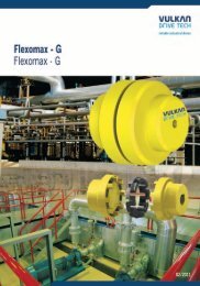
Megiflex - B - 2010/04<br />
02<br />
General Information<br />
This catalogue replaces all prior issues which become thus invalid.<br />
The technical data contained in such catalogue refer to those currently<br />
used by VULKAN DRIVE TECH.<br />
Changes based on technological advances are reserved. In case of<br />
doubt or further clarifications please contact VULKAN.<br />
Issue 2010/04<br />
All rights of duplication, reprinting and translation are reserved.<br />
We reserve the right to modify dimensions and constructions<br />
without prior notice.<br />
Allgemeine Informationen<br />
Dieser Katalog ersetzt alle die vorherige Publikationen, die zur Konsequenz<br />
ungültig werden.<br />
Die technische Daten in diesem Katalog beziehen sich auf die aktuelle<br />
<strong>für</strong> die VULKAN DRIVE TECH benutzt.<br />
Veränderungen aufgrund den technologischen Fortschritt sind reserviert.<br />
Falls haben Sie Zweifel oder möchten Sie sonstige Erklärungen,<br />
bitte melden Sie uns bei VULKAN.<br />
Publikation 2010/04<br />
Alle Rechte bezüglich auf die Abschrift, neu Drucke und Übersetzung<br />
sind reserviert.<br />
Wir reservieren uns auch die Rechte, den Ausmaß und die Konstruktion<br />
ohne vorherige Bescheid zu verändern.<br />
We reserve the right of technical alterations without previous notice. Wir reservieren uns den Recht die technische Veränderungen ohne vorherige Bescheid durchzuführen.
Inhalt<br />
Index<br />
Eigenschaften und Beschreinbung<br />
Characteristics and Description<br />
Kupplungsauswahl<br />
Selection of Couplings<br />
Baureihenübersicht<br />
Summary of Series<br />
Maßtabelle <strong>für</strong> die Baureihen 1700, 1701, 1710, 1711, 1720, 1712, 1740 u. 1750<br />
Dimension Table for Series 1700, 1701, 1710, 1711, 1720, 1712, 1740 and 1750<br />
Maßtabelle <strong>für</strong> die Baureihe 1731 <strong>für</strong> Dieselmotoren mit SAE-Anschluss<br />
Dimension Table for Series 1731 for Diesel Engines with SAE Flywheel<br />
Auslegung der <strong>MEGIFLEX</strong>-B-Kupplung in Gelenkwellenausführung<br />
Selection of <strong>MEGIFLEX</strong>-B Coupling in Cardan Shaft Design<br />
Massenträgheitsmomente/Massen<br />
Mass-Moments of Inertia/Masses<br />
Montageanleitung<br />
Installation Instruction<br />
06<br />
08<br />
09<br />
10<br />
12<br />
13<br />
14<br />
16<br />
03
Megiflex - B - 2010/04<br />
06<br />
EIGENSCHAFTEN UND BESCHREIBUNG<br />
CHARACTERISTICS AND DESCRIPTION<br />
Hochelastische VULKAN-<strong>MEGIFLEX</strong>-B-<strong>Kupplungen</strong> sind drehweiche,<br />
stoßdämpfende, allseits nachgiebige, geräuschdämpfende<br />
und elektrisch isolierende Verbindungselemente, die durch ihre<br />
Baureihenvielfalt den unterschiedlichsten Anforderungen gerecht<br />
werden.<br />
Das elastische Element bietet mit seiner radialen und axialen<br />
Befestigungsmöglichkeit eine große Anzahl an Anwendungsmöglichkeiten,<br />
von Flanschanschlüssen über Welle-Welle-Verbindungen<br />
bis zu drehelastischen Gelenkwellen.<br />
<strong>MEGIFLEX</strong>-B-<strong>Kupplungen</strong> stehen in einem Nennmomentbereich<br />
von 10 Nm bis 3.125 Nm zur Verfügung. Zwei unterschiedliche<br />
Drehfedersteifigkeiten je Baugröße ermöglichen eine<br />
Anpassung der Kupplung an die entsprechenden drehschwingungstechnischen<br />
Erfordernisse.<br />
Die gegebenen technischen Daten stellen Maximalwerte dar, die<br />
nicht zeitgleich auftreten dürfen. Die wechselseitige Beeinflussung<br />
von Betriebszuständen führt zu einer Reduktion dieser Werte und<br />
muß bei der Kupplungsauslegung berücksichtigt werden.<br />
The Highly Flexible VULKAN-<strong>MEGIFLEX</strong>-B Couplings are torsionally<br />
flexible with an excellent multi-directional misalignment<br />
compensation capacity. They are shock-absorbing and have good<br />
electrical isolation and noise attenuation properties. The designs<br />
available permit the installation of the <strong>MEGIFLEX</strong>-B in various<br />
applications.<br />
The flexible element with its axial and radial clamping feature<br />
offers a number of designs, e. g. flange/flange, shaft/shaft, cardanic<br />
shafts.<br />
<strong>MEGIFLEX</strong>-B Couplings are available in the torque range<br />
10–3.125 Nm. With its two torsional stiffnesses/sizes, an effective<br />
tuning of the installation’s torsional vibration behaviour may be<br />
achieved.<br />
The given technical data represent the maximum values, which<br />
may not arise at the same time. The mutual influence of operating<br />
conditions leads to a reduction of these values and must be considered<br />
during the coupling selection.<br />
We reserve the right of technical alterations without previous notice. Wir reservieren uns den Recht die technische Veränderungen ohne vorherige Bescheid durchzuführen.
Baugröße Baugruppe Nenndrehmoment<br />
Size Dimension<br />
Group<br />
Liste der Technischen Daten<br />
List of Technical Data<br />
Nominal<br />
Torque<br />
T KN 1)<br />
Nm<br />
Max.<br />
Drehmoment<br />
Max.<br />
Torque<br />
T K max.<br />
Nm<br />
Zul. Wechseldrehmoment<br />
Perm.<br />
Vibratory<br />
Torque<br />
T KW<br />
Nm<br />
Zul.<br />
Verlustleistung<br />
Perm.<br />
Power<br />
Loss<br />
P KW 30 2) 4)<br />
W<br />
Zul.<br />
Drehzahl<br />
Perm.<br />
Rotational<br />
Speed<br />
n K max<br />
1/min<br />
Zul. radialer<br />
Wellenversatz<br />
Perm. Radial<br />
Shaft Displacement<br />
ΔK r 7)<br />
mm<br />
Radiale<br />
Federsteife<br />
Radial<br />
Stiffness s<br />
C rdyn<br />
N/mm<br />
Zul. axialer<br />
Wellenversatz<br />
Perm. Axia<br />
Shaft Displacement<br />
ΔK a<br />
mm<br />
Axiale<br />
Federsteife<br />
Axial<br />
Stiffness<br />
C axial<br />
N/mm<br />
Zul. winkliger<br />
Wellenversatz<br />
Perm. Angular<br />
Shaft Displacement<br />
ΔKW 7)<br />
Grad<br />
Winklige<br />
Federsteife<br />
Angular<br />
Stiffness<br />
C wdyn<br />
Nm/Grad<br />
Dynamische<br />
Drehfedersteife<br />
Dynamic<br />
Torsional<br />
Stiffness<br />
0421<br />
0422<br />
0420<br />
10,00<br />
12,50<br />
20,0<br />
30,0<br />
5,0<br />
6,2<br />
25 10000<br />
1,5<br />
1,0<br />
130<br />
195<br />
2,0<br />
1,3<br />
25<br />
38<br />
3,0°<br />
2,1°<br />
0,27<br />
0,40<br />
80<br />
110<br />
0621<br />
0622<br />
0620<br />
20,00<br />
25,00<br />
40,0<br />
60,0<br />
10,0<br />
12,5<br />
35 8000<br />
1,5<br />
1,0<br />
130<br />
195<br />
3,0<br />
2,0<br />
15<br />
22<br />
3,0°<br />
2,1°<br />
0,27<br />
0,40<br />
160<br />
220<br />
0831<br />
0832<br />
0830<br />
40,00<br />
50,00<br />
80,0<br />
120,0<br />
20,0<br />
25,0<br />
45 7000<br />
1,5<br />
1,0<br />
435<br />
650<br />
3,0<br />
2,0<br />
50<br />
75<br />
3,0°<br />
2,1°<br />
2,10<br />
3,10<br />
460<br />
650<br />
1031<br />
1032<br />
1030<br />
80,00<br />
100,00<br />
160,0<br />
240,0<br />
40,0<br />
50,0<br />
60 6500<br />
2,0<br />
1,3<br />
435<br />
650<br />
4,0<br />
2,7<br />
50<br />
75<br />
3,0°<br />
2,1°<br />
3,10<br />
4,20<br />
820<br />
1150<br />
1041<br />
1042<br />
1040<br />
120,00<br />
150,00<br />
240,0<br />
360,0<br />
60,0<br />
75,0<br />
75 6500<br />
2,0<br />
1,3<br />
870<br />
1300<br />
4,0<br />
2,7<br />
170<br />
250<br />
2,0°<br />
1,4°<br />
8,20<br />
11,70<br />
2550<br />
3550<br />
1231<br />
1232<br />
1230<br />
160,00<br />
200,00<br />
320,0<br />
480,0<br />
80,0<br />
100,0<br />
70 6000<br />
2,0<br />
1,3<br />
435<br />
650<br />
5,0<br />
3,3<br />
67<br />
100<br />
3,0°<br />
2,1°<br />
4,30<br />
6,50<br />
1850<br />
2600<br />
1241<br />
1242<br />
1240<br />
220,00<br />
275,00<br />
440,0<br />
660,0<br />
110,0<br />
138,0<br />
90 6000<br />
2,0<br />
1,3<br />
1135<br />
1700<br />
5,0<br />
3,3<br />
340<br />
500<br />
2,0°<br />
1,4°<br />
10,90<br />
15,60<br />
5850<br />
8000<br />
1431<br />
1432<br />
1430<br />
250,00<br />
312,50<br />
500,0<br />
750,0<br />
125,0<br />
156,0<br />
80 5000<br />
2,0<br />
1,3<br />
520<br />
780<br />
5,0<br />
3,3<br />
95<br />
140<br />
3,0°<br />
2,1°<br />
6,10<br />
9,10<br />
2650<br />
3700<br />
1441<br />
1442<br />
1440<br />
340,00<br />
425,00<br />
680,0<br />
1020,0<br />
170,0<br />
212,0<br />
95 5000<br />
2,0<br />
1,3<br />
1220<br />
1820<br />
5,0<br />
3,3<br />
370<br />
550<br />
2,0°<br />
1,4°<br />
15,50<br />
22,10<br />
6850<br />
9500<br />
1631<br />
1632<br />
1630<br />
400,00<br />
500,00<br />
800,0<br />
1200,0<br />
200,0<br />
250,0<br />
90 4000<br />
2,0<br />
1,3<br />
650<br />
975<br />
5,0<br />
3,3<br />
130<br />
190<br />
3,0°<br />
2,1°<br />
8,20<br />
11,70<br />
4100<br />
5750<br />
1641<br />
1642<br />
1640<br />
600,00<br />
750,00<br />
1200,0<br />
1800,0<br />
300,0<br />
375,0<br />
110 4500<br />
2,0<br />
1,3<br />
1900<br />
2850<br />
5,0<br />
3,3<br />
430<br />
650<br />
2,0°<br />
1,4°<br />
22,50<br />
33,80<br />
10900<br />
15300<br />
1741<br />
1742<br />
1740<br />
800,00<br />
1000,00<br />
1600,0<br />
2400,0<br />
400,0<br />
500,0<br />
100 4500<br />
1,5<br />
1,0<br />
2500<br />
3750<br />
3,0<br />
2,0<br />
570<br />
850<br />
2,0°<br />
1,4°<br />
30,90<br />
44,20<br />
13700<br />
19500<br />
2131<br />
2132<br />
2130<br />
900,00<br />
1125,00<br />
1800,0<br />
2700,0<br />
450,0<br />
563,0<br />
120 3600<br />
2,0<br />
1,3<br />
850<br />
1300<br />
5,0<br />
3,3<br />
150<br />
220<br />
3,0°<br />
2,1°<br />
14,70<br />
22,10<br />
10500<br />
14700<br />
2141<br />
2142<br />
2140<br />
1400,00<br />
1750,00<br />
2800,0<br />
4200,0<br />
700,0<br />
875,0<br />
135 3600<br />
2,0<br />
1,3<br />
2000<br />
3000<br />
5,0<br />
3,3<br />
430<br />
650<br />
2,0°<br />
1,4°<br />
34,60<br />
49,40<br />
24400<br />
34500<br />
2841<br />
2842<br />
2840<br />
2500,00<br />
3125,00<br />
5000,0 1250,0<br />
7500,0 1563,0<br />
170 3000<br />
2,0<br />
1,3<br />
3560<br />
5350<br />
5,0<br />
3,3<br />
800<br />
1150<br />
2,0°<br />
1,4°<br />
61,90<br />
88,40<br />
48750<br />
78500<br />
C Tdyn 3) 5) 6)<br />
Nm/rad<br />
Verhältnismäßige<br />
Dämpfung<br />
Relative<br />
Damping<br />
0,75<br />
0,75<br />
0,75<br />
0,75<br />
0,75<br />
0,75<br />
0,75<br />
0,75<br />
0,75<br />
0,75<br />
0,75<br />
0,75<br />
0,75<br />
0,75<br />
0,75<br />
MB-LTD-1<br />
We reserve the right of technical alterations without previous notice. Wir reservieren uns den Recht die technische Veränderungen ohne vorherige Bescheid durchzuführen.<br />
07<br />
Megiflex - B - 2010/04
Megiflex - B - 2010/04<br />
08<br />
1) Bei der Auswahl der <strong>Kupplungen</strong> sind die Dauerleistungen<br />
der Motoren zugrunde zu legen, Überleistungen, Höchst-<br />
und Kurz-Höchstleistungen nach DIN 6271 brauchen nicht<br />
berücksichtigt zu werden.<br />
2) Die aufgeführten Werte beziehen sich auf die dynamische<br />
Drehfedersteife bei f = 10 Hz und ϑ = 303 K (30°C) und einer<br />
Prüfamplitude von 20% TKN.<br />
3) Bei thermisch hochbelasteten <strong>Kupplungen</strong> empfehlen wir<br />
eine Kontrollrechnung mit 70% CTdyn – besonders wichtig bei<br />
Anlagen mit konstanter Drehzahl.<br />
4) Die alleinige Betrachtung des zulässigen Wechselmomentes ist<br />
nicht ausreichend. In jedem Fall muss die Belastung durch<br />
die Verlustleistung überprüft werden und in zulässigen Gren-<br />
zen liegen (Synthesewert).<br />
5) Die Tabellenwerte PKV in der Liste der technischen<br />
Daten beziehen sich auf eine Umgebungstemperatur von 30°C<br />
(303 K). Bei Umgebungstemperaturen von 60°C (333 K):<br />
PKV60 = PKV30 · 0,65<br />
Bei Umgebungstemperaturen von 80°C (353 K):<br />
PKV80 = PKV30 · 0,40<br />
6) Bedingt durch die physikalischen Eigenschaften der elastischen<br />
Elemente sind <strong>für</strong> die angegebenen Werte Toleranzen von<br />
± 35% möglich.<br />
7) Die zulässige Winkel- und Radialverlagerung ist abhän<br />
gig von der Drehzahl. Im Drehzahlbereich bis n = 1.500 min -1<br />
gelten bei Ausnutzung der Nennleistung die oben angegebenen<br />
Verlagerungswerte. Bei Drehzahlen über 1.500 min -1 reduziert<br />
sich die Verlagerungsfähigkeit um 30% je 1.000 min -1 Drehzahl<br />
steigerung.<br />
Technische Daten <strong>für</strong> Silikon-Elemente auf Anfrage.<br />
MB-LTD-1<br />
1) When selecting couplings the permanent output of the engine is<br />
to be taken as a basis. Overloads, peak and short peak outputs<br />
acc. to DIN 6271 need not to be taken into consideration.<br />
2) The stated values refer to the dynamic torsional stiffness at f = 10<br />
Hz and ϑ = 303 K (30°C) and a test-amplitude of 20% TKN.<br />
3) With couplings subjected to high thermal loading we recommend<br />
to use 70% CTdyn for a control calculation – very important for<br />
applications with constant speed drives.<br />
4) It is not sufficient to consider only permissible vibratory torque.<br />
In every case the power loss loading must be checked and it must<br />
be within permissible limits (synthesis value).<br />
5) The values of PKV in the list of technical data are based on an<br />
ambient temperature of 30°C (303 K).<br />
At an ambient temperature of 60°C (333 K)<br />
PKV60 = PKV30 · 0.65<br />
At an ambient temperature of 80°C (353 K)<br />
PKV80 = PKV30 · 0.40<br />
6) Due to the physical characteristics of the elastic elements, tole<br />
rances of ± 35% are possible in the mentioned values.<br />
7) The permissible angular and radial displacement depends on the<br />
speed. In the speed range up to n = 1,500 rpm the a.m. displace-<br />
ment values are valid during the utilization of the nominal capa-<br />
city. In case of speed exceeding 1,500 rpm the displacement ability<br />
reduces by 30% each 1,000 rpm speed increase.<br />
Technical data for silicone elements on request.<br />
We reserve the right of technical alterations without previous notice. Wir reservieren uns den Recht die technische Veränderungen ohne vorherige Bescheid durchzuführen.
Kupplungsauswahl<br />
Selection of Couplings<br />
Da eine Kupplungsauslegung nach DIN 740 nicht alle Betriebszustände<br />
berücksichtigt, muß eine Bestätigung der Kupplungsauswahl<br />
bei VULKAN eingeholt werden.<br />
Für industrielle Anwendung sind in Anlehnung an DIN 740 folgende<br />
Auslegungskriterien zu beachten:<br />
Beanspruchung durch das Nenndrehmoment<br />
Die überschlägige Auswahl der Kupplung erfolgt nach dem Nenndrehmoment<br />
der Lastseite unter Berücksichtigung der Temperatur.<br />
TKN ≥ TN · Sϑ<br />
TKN = zulässiges Nenndrehmoment der Kupplung<br />
TN = Anlagendrehmoment<br />
Sϑ = Temperaturfaktor, der die Umgebungstemperatur der<br />
Kupplung beim Betrieb berücksichtigt<br />
Temperaturfaktor Sϑ:<br />
ϑ [C°]<br />
–20 ≥ ϑ < +40<br />
+40 ≥ ϑ < +50<br />
+50 ≥ ϑ < +60<br />
+60 ≥ ϑ < +80<br />
Sϑ<br />
<strong>für</strong> Naturgummi (NR)<br />
1,0<br />
1,1<br />
1,3<br />
1,6<br />
Beanspruchung durch Drehmomentstöße<br />
Das zulässige Maximaldrehmoment der Kupplung muss bei<br />
jeder Betriebstemperatur mindestens so groß sein wie die im<br />
Betrieb auftretenden Drehmomentstöße unter Berücksichtigung<br />
der Stoßhäufigkeit.<br />
TK max. = Drehmoment, das als schwellende oder wechselnde<br />
Beanspruchung kurze Zeit ertragen werden kann<br />
TS = Spitzendrehmoment an der Kupplung<br />
SZ = Anlauffaktor, der die Anfahrhäufigkeit Z berücksichtigt<br />
Sϑ = Temperaturfaktor<br />
Anlauffaktor SZ (<strong>für</strong> elektromotorische Antriebe):<br />
Z in h-1<br />
Sz<br />
TAS = Spitzendrehmoment der Antriebsseite<br />
TLS = Spitzendrehmoment der Lastseite<br />
JA = Massenträgheitsmoment der Antriebsseite<br />
JL = Massenträgheitsmoment der Lastseite<br />
SA/SL = Stoßfaktor<br />
Stoßfaktor SA/SL:<br />
≤ 120<br />
1,0<br />
TK max. ≥ TS · SZ · Sϑ<br />
120 < Z ≤ 240<br />
1,3<br />
Spitzendrehmoment TS:<br />
Antriebseitiger Stoß: TS = TAS ·<br />
JL<br />
JA + JL<br />
· SA<br />
JA<br />
Lastseitiger Stoß: TS = TAS · · SA<br />
JA + JL<br />
Leichte Anfahrtstöße 1,6<br />
Mittlere Anfahrtstöße 1,9<br />
Schwere Anfahrtstöße 2,2<br />
> 240<br />
Rückfrage beim<br />
Hersteller<br />
Due to the fact that a coupling selection according to DIN 740 will<br />
not cover all application influences, any selection must be confirmed<br />
by VULKAN.<br />
The following criteria of selection for industrial application have to be<br />
considered with reference to DIN 740:<br />
Stress arising from nominal torque<br />
The rough selection of the coupling is made according to the nominal<br />
output torque with regard to the temperature.<br />
TKN ≥ TN · Sϑ<br />
TKN = permissible nominal torque of the coupling<br />
TN = nominal torque of the system<br />
Sϑ = temperature coefficient which considers the ambient<br />
temperature during operation<br />
Temperature coefficient Sϑ:<br />
We reserve the right of technical alterations without previous notice. Wir reservieren uns den Recht die technische Veränderungen ohne vorherige Bescheid durchzuführen.<br />
ϑ [C°]<br />
–20 ≥ ϑ < +40<br />
+40 ≥ ϑ < +50<br />
+50 ≥ ϑ < +60<br />
+60 ≥ ϑ < +80<br />
Sϑ<br />
for natural rubber (NR)<br />
1.0<br />
1.1<br />
1.3<br />
1.6<br />
Stress arising form torque impulses<br />
The permissible maximum torque at the coupling shall be at least<br />
equal to the torque impulses occuring during operation at all operating<br />
temperatures, taking the frequency of the impulses into consideration.<br />
TK max. = torque resulting from pulsating or alternating stress, which<br />
a coupling can resist without failure for a short period of time<br />
TS = peak torque, maximum torque at the coupling<br />
SZ = coefficient that makes allowance for the additional loading<br />
caused by the frequency of starts<br />
Sϑ = temperature coefficient<br />
Starting coefficient SZ (for electric motors):<br />
Z in h-1<br />
Sz<br />
≤ 120<br />
1.0<br />
TAS = peak value of the non-periodic, input torque impulses<br />
TLS = peak value of the non-periodic, output torque impulses<br />
JA = mass moment of inertia, input side<br />
JL = mass moment of inertia, output side<br />
SA/SL = impulse coefficient<br />
impulse coefficient SA/SL:<br />
TK max. ≥ TS · SZ · Sϑ<br />
120 < Z ≤ 240<br />
1.3<br />
Peak torque TS:<br />
Input torque impulses: TS = TAS ·<br />
JL<br />
· SA<br />
JA + JL<br />
JA<br />
Output torque impulses: TS = TAS · · SA<br />
JA + JL<br />
slight starting impulses 1.6<br />
middle starting impulses 1.9<br />
heavy starting impulses 2.2<br />
> 240<br />
Please consult<br />
manufacturer<br />
MB-KA-01<br />
09<br />
Megiflex - B - 2010/04
Megiflex - B - 2010/04<br />
10<br />
Baureihenübersicht<br />
Summary of Series<br />
<strong>MEGIFLEX</strong>-B Baureihen-Nr.<br />
Series No.<br />
1700<br />
1701<br />
1710<br />
1711<br />
Baugruppe<br />
Dimension<br />
Group<br />
0420<br />
·<br />
2840<br />
0420<br />
·<br />
2840<br />
0420<br />
·<br />
2840<br />
0420<br />
·<br />
2840<br />
T KN<br />
kNm<br />
10<br />
·<br />
3125<br />
10<br />
·<br />
3125<br />
10<br />
·<br />
3125<br />
10<br />
·<br />
3125<br />
Beschreibung<br />
Description<br />
Elastisches Element als Basis <strong>für</strong> beliebige Sonderkonstruktionen,<br />
lieferbar in zwei Steifigkeiten je Baugröße<br />
Flexible element as a basis for all various special<br />
designs,<br />
available in two stiffnesses per size<br />
Steckbare Variante der Bauform 1700<br />
Axial “Plug-in” variant of the design 1700<br />
Bauform zur Verbindung einer Welle mit unterschiedlichsten<br />
Antriebselementen, wie z. B. Riemenscheiben,<br />
Bremsscheiben, Schwungräder etc.<br />
Design for connection of a shaft with different<br />
drive components, e.g. with pulley, brake pulley,<br />
flywheels etc.<br />
Steckbare Variante der Anbauform 1710<br />
mit dem Vorteil der erleichterten Montage<br />
Axial “Plug-in” variant of the design 1710<br />
with the advantage of easy assembly<br />
<strong>MEGIFLEX</strong>-B<br />
Baureihen-Nr.<br />
Series No.<br />
Baugruppe<br />
Dimension<br />
Group<br />
Beschreibung<br />
Description<br />
We reserve the right of technical alterations without previous notice. Wir reservieren uns den Recht die technische Veränderungen ohne vorherige Bescheid durchzuführen.<br />
1720<br />
1721<br />
1730<br />
1731<br />
1740<br />
1750<br />
0420<br />
·<br />
2840<br />
0420<br />
·<br />
2840<br />
0420<br />
·<br />
2840<br />
0420<br />
·<br />
2840<br />
T KN<br />
kNm<br />
10<br />
·<br />
3125<br />
10<br />
·<br />
3125<br />
10<br />
·<br />
3125<br />
10<br />
·<br />
3125<br />
Bauform zur Verbindung zweier Wellen<br />
Design for the connection of two shafts<br />
Steckbare Variante der Bauform 1720<br />
Axial “Plug-in” variant of the design 1720<br />
Zur Verbindung eines SAE-Schwungrades J 620<br />
mit einer Welle<br />
For the connection of a SAE-flywheel J 620 with<br />
a shaft<br />
Drehelastische Gelenkwellenausführung<br />
Radialer Ausbau des Kupplungsmittelteils<br />
ohne Verschieben der verbundenen Maschinen<br />
Torsionally flexible cardan shaft design<br />
Radial removal of the couplings centre piece<br />
without displacement of the connected machinery
<strong>Abmessungen</strong><br />
Dimensions<br />
Baureihe<br />
Series<br />
Baureihe<br />
Series<br />
Baugruppe Nenndreh<br />
moment<br />
Dimension<br />
Group<br />
1700<br />
1701<br />
Nominal<br />
Torque<br />
T KN<br />
Nm<br />
Ø D5<br />
Ø D5<br />
Ø S3<br />
L8 Ø D3<br />
Ø S4<br />
L8 Ø D3<br />
vergeb.<br />
Pilot bored<br />
L6<br />
Ø S2<br />
Ø S3<br />
L7<br />
L4<br />
L5 L9<br />
L6<br />
ØS2<br />
Ø S3<br />
L4<br />
L5 L9<br />
Ø S2<br />
<strong>Abmessungen</strong><br />
Dimensions<br />
D 1 D 2 D 3 D 4 D 5 D 6 H 3 L 1 L 2 L 4 L 5 L 6 L 7<br />
max. vergeb.<br />
Pilot bored<br />
Ø LKr2 T-Teilung / Holes<br />
LKr2 T-Teilung / Holes<br />
max.<br />
Baureihe<br />
Series<br />
Baureihe<br />
Series<br />
L6 L10<br />
0420 10,00 - 12,50 – 19,00 8,00 25,00 30,00 36,00 56,00 52,00 7 26,00 50,00 11,00 22,00 24,00 18,00<br />
0620 20,00 - 25,00 – 26,00 12,00 38,00 40,00 55,00 85,00 80,00 8 32,00 60,00 10,00 20,00 24,00 12,00<br />
0830 40,00 - 50,00 – 30,00 15,00 45,00 45,00 65,00 100,00 95,00 8 34,00 64,00 12,00 24,00 28,00 17,00<br />
1030 80,00 - 100,00 – 38,00 18,00 55,00 60,00 80,00 120,00 115,00 10 46,00 88,00 14,00 28,00 32,00 20,50<br />
1040 120,00 - 150,00 – 38,00 18,00 55,00 60,00 80,00 122,00 115,00 10 46,00 88,00 14,00 28,00 32,00 20,50<br />
1230 160,00 - 200,00 – 48,00 20,00 70,00 70,00 100,00 150,00 145,00 12 56,00 106,00 18,00 36,00 42,00 23,50<br />
1240 220,00 - 275,00 – 48,00 20,00 70,00 70,00 100,00 150,00 145,00 12 56,00 106,00 18,00 36,00 42,00 23,50<br />
1430 250,00 - 312,50 – 55,00 20,00 85,00 85,00 115,00 170,00 165,00 14 61,00 116,00 20,00 40,00 46,00 26,00<br />
1440 340,00 - 425,00 – 55,00 20,00 85,00 85,00 115,00 170,00 165,00 14 61,00 116,00 20,00 40,00 46,00 26,00<br />
1630 400,00 - 500,00 – 65,00 25,00 100,00 100,00 140,0 200,00 195,00 16 74,00 140,00 25,00 50,00 58,00 34,50<br />
1640 600,00 - 750,00 – 65,00 25,00 100,00 100,00 140,00 200,00 195,00 16 74,00 140,00 25,00 50,00 58,00 34,50<br />
1740 800,00 - 1000,00 – 65,00 25,00 100,00 100,00 140,00 205,00 195,00 16 70,00 136,00 30,50 61,00 65,00 34,50<br />
2130 900,00 - 1125,00 – 85,00 30,00 110,00 125,00 160,00 260,00 250,00 19 88,00 168,00 31,00 62,00 70,00 45,50<br />
2140 1400,00 - 1750,00 – 85,00 30,00 110,00 125,00 160,00 260,00 250,00 19 88,00 168,00 31,00 62,00 70,00 45,50<br />
2840 2500,00 - 3125,00 – 115,00 40,00 130,00 160,00 195,00 340,00 330,00 19 108,00 208,00 22,50 77,00 85,00 60,00<br />
Maße in mm Dimensions in mm<br />
We reserve the right of technical alterations without previous notice. Wir reservieren uns den Recht die technische Veränderungen ohne vorherige Bescheid durchzuführen.<br />
1710<br />
1711<br />
Ø D5<br />
Ø D5<br />
Ø D3<br />
Ø D3<br />
Ø D1<br />
Ø D1 Ø S4<br />
L5<br />
L4<br />
N1 L9<br />
L1<br />
L6<br />
L5<br />
L4<br />
N1 L9<br />
L1<br />
S5<br />
L12<br />
S5<br />
LKr2 T-Teilung / Holes<br />
LKr2 T-Teilung / Holes<br />
MB-A-1700-1<br />
11<br />
Megiflex - B - 2010/04
Megiflex - B - 2010/04<br />
12<br />
Baureihe<br />
Series<br />
Baureihe<br />
Series<br />
<strong>Abmessungen</strong><br />
Dimensions<br />
Ø D3<br />
Ø D1<br />
Ø D3<br />
Ø D1<br />
1721<br />
<strong>Abmessungen</strong> Nenndreh<br />
moment<br />
Baugruppe<br />
Dimensions Nominal Torque Dimension<br />
Group<br />
L 8 L 9 L 10 L 11 L 12 L 13 L KR2 N 1 N 2 S 2 S 3 S 4 S 5 S 6 T Z T T KN<br />
Nm<br />
5,0 2,00 7,00 8 7<br />
L4 H3<br />
L5 L9<br />
N1 N2<br />
L5<br />
L4<br />
L2<br />
H3<br />
N1 N2<br />
L2<br />
L9<br />
auf Anfrage unter Berücksichtigung des<br />
Diagramm auf Seite 13<br />
on request under consideration of the<br />
diagram on page 13<br />
Ø D2<br />
Ø D2<br />
Ø D4<br />
Ø D4<br />
Ø D5<br />
Ø D5<br />
44,00 24,00 24 6,50 10,20 10,0 M6 M6 2,00 1,5 10,00 - 12,50 0420<br />
14,2 4,00 8,00 10 8 68,00 28,00 28 8,50 13,50 14,0 M8 M8 2,00 1,5 20,00 - 25,00 0620<br />
18,5 4,00 8,00 11 8 80,00 30,00 30 8,50 13,50 14,0 M8 M8 3,00 1,5 40,00 - 50,00 0830<br />
20,5 4,00 9,50 16 10 100,00 42,00 42 10,50 16,50 17,0 M10 M10 3,00 1,5 80,00 - 100,00 1030<br />
20,5 4,00 9,50 16 10 100,00 42,00 42 10,50 16,50 17,0 M10 M10 4,00 1,5 120,00 - 150,00 1040<br />
25,2 6,00 11,50 19 12 125,00 50,00 50 12,50 18,50 19,0 M12 M12 3,00 1,5 160,00 - 200,00 1230<br />
25,2 6,00 11,50 19 12 125,00 50,00 50 12,50 18,50 19,0 M12 M12 4,00 1,5 220,00 - 275,00 1240<br />
27,0 6,00 14,00 20 14 140,00 55,00 55 14,50 21,50 22,0 M14 M14 3,00 1,5 250,00 - 312,50 1430<br />
27,0 6,00 14,00 20 14 140,00 55,00 55 14,50 21,50 22,0 M14 M14 4,00 1,5 340,00 - 425,00 1440<br />
34,5 8,00 15,50 25 16 165,00 66,00 66 16,50 24,50 25,0 M16 M16 3,00 1,5 400,00 - 500,00 1630<br />
34,5 9,00 15,50 25 16 165,00 66,00 66 16,50 24,50 25,0 M16 M16 4,00 1,5 600,00 - 750,00 1640<br />
34,5 4,00 15,50 25 16 165,00 66,00 66 16,50 24,50 25,0 M16 M16 4,00 1,5 800,00 - 1000,00 1740<br />
47,0 8,00 19,95 30 20 215,00 80,00 80 20,50 30,50 32,0 M20 M16 3,00 1,5 900,00 - 1125,00 2130<br />
47,0 8,00 19,50 30 20 215,00 80,00 80 20,50 30,50 32,0 M20 M16 4,00 1,5 1400,00 - 1750,00 2140<br />
59,0 8,00 20,00 40 20 280,00 100,00 100 20,50 62,50 32,0 M20 M16 4,00 1,5 2500,00 - 3125,00 2840<br />
Maße in mm Dimensions in mm<br />
MB-A-1720-1<br />
1720<br />
Baureihe<br />
Series<br />
Baureihe<br />
Series<br />
Ø D5<br />
1740<br />
Ø D4<br />
We reserve the right of technical alterations without previous notice. Wir reservieren uns den Recht die technische Veränderungen ohne vorherige Bescheid durchzuführen.<br />
Ø D2<br />
Ø D5<br />
Ø D6<br />
Ø D4<br />
Ø D2<br />
1750<br />
N2 L13 Auf Anfrage / on request<br />
N2<br />
H3 L6<br />
L6 H3<br />
L11 L11<br />
S6<br />
N2<br />
L9<br />
H3<br />
L4 L4<br />
L5 L5 L9<br />
L13 Auf Anfrage / on request<br />
L11 L6<br />
L6<br />
L11<br />
S6 S6<br />
ZT<br />
L9<br />
L4<br />
L4<br />
H3<br />
L5 L5 L9<br />
ZT<br />
N2<br />
S6<br />
Ø D2<br />
Ø D4<br />
Ø D5<br />
Ø D2<br />
Ø D4<br />
Ø D6<br />
Ø D5
<strong>Abmessungen</strong><br />
<strong>MEGIFLEX</strong>-B-<strong>Kupplungen</strong> <strong>für</strong> Dieselmotoren mit SAE-Schwungrad<br />
Dimensions<br />
<strong>MEGIFLEX</strong>-B Couplings for Diesel Engines with SAE-Flywheel<br />
Maße in mm<br />
Ø D5<br />
Ø D3<br />
Baugruppe Nenndreh<br />
moment<br />
Dimension<br />
Group<br />
1030<br />
1230<br />
1240<br />
1430<br />
1440<br />
1630<br />
1640<br />
2130<br />
2140<br />
2840<br />
Nominal<br />
Torque<br />
T KN<br />
Nm<br />
Ø D1<br />
L3<br />
L6<br />
Ø S1<br />
L5<br />
Baureihe<br />
Series<br />
L4<br />
N1 L9<br />
H1<br />
H2<br />
1730<br />
Ø D6<br />
Ø LKr1 T-Teilung / Holes<br />
Ø Z js7<br />
Schwungrad <strong>Abmessungen</strong><br />
Flywheel Dimensions<br />
Ø D5<br />
Ø D3<br />
Ø D1<br />
L3<br />
L6<br />
Ø S1<br />
L5<br />
L4<br />
N1 L9<br />
Baureihe<br />
Series<br />
H1<br />
H2<br />
Ø D6<br />
1731<br />
SAE D 1 D 3 D 5 D 6 H 1 H 2 L 3 L 4 L 5 L 6 L 9 L KR1 N 1 S 1 T Z<br />
vergeb.<br />
Pilot bored<br />
max.<br />
80,00 - 6,5<br />
12,00 38,00 60,00 120,00 180,00<br />
100,00 7,5 200,00<br />
6,00 10,00 52,00 14,00 28,00 32,00 4,00<br />
200,00<br />
222,30<br />
42,00<br />
9,00<br />
9,00<br />
6,00<br />
8,00<br />
215,90<br />
241,30<br />
160,00- 6,5<br />
180,00<br />
200,00<br />
9,00 6,00 215,90<br />
7,5 15,00 48,00 70,00 150,00 200,00 6,00 12,00 62,00 18,00 36,00 42,00 6,00 222,30 50,00 9,00 8,00 241,30<br />
200,00 8,0 220,00 244,50 11,00 6,00 263,50<br />
220,00-<br />
275,00<br />
6,5 15,00 48,00 70,00 150,00 180,00 6,00 12,00 62,00 18,00 36,00 42,00 6,00 200,00 50,00 9,00 6,00 215,90<br />
250,00- 8,0<br />
15,00 55,00 85,00 170,00 220,00 6,00 312,50 10,0 270,00 10,00<br />
14,00<br />
67,00<br />
71,00<br />
20,00 40,00 46,00 6,00<br />
244,50<br />
295,30<br />
55,00<br />
11,00<br />
11,00<br />
6,00<br />
8,00<br />
263,50<br />
314,30<br />
340,00-<br />
425,00<br />
8,0 15,00 55,00 85,00 170,00 220,00 6,00 14,00 67,00 20,00 40,00 46,00 6,00 244,50 55,00 11,00 6,00 263,50<br />
400,00- 10,0<br />
20,00 65,00 100,00 200,00 270,00 10,00 16,00 84,00 25,00 50,00 58,00 8,00<br />
295,30<br />
66,00 11,00<br />
8,00 314,30<br />
500,00 11,5 310,00 333,40 11,00 352,40<br />
600,00- 10,0<br />
20,00 65,00 100,00 200,00 270,00 10,00 16,00 84,00 25,00 50,00 58,00 8,00<br />
295,30<br />
66,00 11,00<br />
8,00 314,30<br />
750,00 11,5 310,00 333,40 11,00 352,40<br />
900,00- 11,5<br />
30,00 85,00 125,00 260,00 310,00 10,00 19,00 98,00 31,00 62,00 70,00 8,00<br />
333,40<br />
80,00 11,00<br />
8,00 352,40<br />
1125,00 14,0 405,00 438,20 13,00 466,70<br />
1400,00- 11,5<br />
30,00 85,00 125,00 260,00 310,00 10,00 19,00 98,00 31,00 62,00 70,00 8,00<br />
333,40<br />
80,00 11,00<br />
8,00 352,40<br />
1750,00 14,0 405,00 438,20 13,00 466,70<br />
2500,00 11,5<br />
40,00 115,00 160,00 340,00 310,00 10,00 19,00 118,00 22,50 77,00 85,00 8,00<br />
333,40<br />
100,00<br />
11,00<br />
8,00 352,40<br />
3125,00 14,0 405,00 438,20 13,00 466,70<br />
Ø LKr1 T-Teilung / Holes<br />
Ø Z js7<br />
MB-A-1730-1<br />
We reserve the right of technical alterations without previous notice. Wir reservieren uns den Recht die technische Veränderungen ohne vorherige Bescheid durchzuführen.<br />
Dimensions in mm<br />
13<br />
Megiflex - B - 2010/04
Megiflex - B - 2010/04<br />
14<br />
Gelenkwellenausführung<br />
Cardan Shaft Design<br />
Auslegung der Baureihe 1740<br />
Die Gelenkwellenausführung gemäß Baureihe 1740 ist geeignet<br />
<strong>für</strong> kleine und mittlere Baulängen bei einer maximalen Drehzahl<br />
von n = 1.800 min -1. Die maximal zulässige Länge des Mittelteils<br />
ist abhängig von der Drehzahl und der Baugröße der Kupplung,<br />
eine entsprechende Kupplungsauswahl nehmen Sie bitte anhand<br />
des unten stehenden Diagramms vor.<br />
Hinsichtlich der technischen Daten ergeben sich <strong>für</strong> die hier<br />
vorliegende Reihenschaltung zweier <strong>MEGIFLEX</strong>-B-Elemente folgende<br />
Veränderungen:<br />
– der Wert CTdyn wird halbiert<br />
– die axiale Steifigkeit Caxial wird halbiert<br />
Auslegung der Baureihe 1750, Gelenkwellenausführung<br />
mit Innenlagerung.<br />
Oberhalb einer Drehzahl von n = 1.800 min -1 muß die <strong>MEGIFLEX</strong>-B-<br />
Gelenkwelle innen gelagert werden.<br />
Für eine sichere Auslegung im konkreten Einsatzfall bitten wir um<br />
Rücksprache mit dem Stammhaus.<br />
Selection of series 1740<br />
The cardan shaft design according to series 1740 is suitable for small<br />
and medium overall lengths at a max. speed of n = 1,800 rpm. The<br />
max. permissible length of the centre section piece depends on the<br />
speed and the size of the coupling, a corresponding coupling selection<br />
can be made, using the below mentioned diagram.<br />
Regarding the technical data, following changes result from the present<br />
series connection of two <strong>MEGIFLEX</strong>-B elements:<br />
– the value CTdyn will be halved<br />
– the axial stiffness Caxial will be halved<br />
Selection of series 1750, cardan shaft design with<br />
internal bearing.<br />
At speeds above n = 1,800 rpm the <strong>MEGIFLEX</strong>-B cardan shaft has<br />
to be internally supported.<br />
For a safe selection in a defined installation please contact VULKAN.<br />
We reserve the right of technical alterations without previous notice. Wir reservieren uns den Recht die technische Veränderungen ohne vorherige Bescheid durchzuführen.
Massenträgheitsmomente/Massen<br />
Mass-Moments of Inertia/Masses<br />
Baugruppe<br />
Dimension<br />
Group<br />
0420<br />
0620<br />
0830<br />
1030<br />
1040<br />
1230<br />
1240<br />
1430<br />
1440<br />
1630<br />
1640<br />
1740<br />
2130<br />
2140<br />
2840<br />
Maße in mm<br />
Baureihe<br />
Series<br />
1700<br />
Baureihe<br />
Series<br />
1701<br />
Baureihe<br />
Series<br />
1710<br />
J= Massenträgheitsmoment kgm 2 x 10 -4 m = Masse kg<br />
Baureihe<br />
Series<br />
Baureihe 1700 Baureihe 1701 Baureihe 1710 Baureihe 1711<br />
1711<br />
J = Mass moment of inertia kgm 2 x 10 -4 Series 1700 Series 1701<br />
m = Mass kg<br />
Series 1710 Series 1711<br />
TKN J1 J2 m1 m2 mges. J1 J2 m1 m2 mges. J1 J2 m1 m2 mges. J1 J2 m1 m2 mges. Nm<br />
10,00-<br />
12,50<br />
20,00-<br />
25,00<br />
40,00-<br />
50,00<br />
80,00-<br />
100,00<br />
120,00-<br />
150,00<br />
160,00-<br />
200,00<br />
0,180 0,180 0,030 0,030 0,06 0,180 0,180 0,030 0,030 0,06 0,300 0,400 0,050 0,170 0,22 0,300 0,400 0,060 0,170 0,23<br />
0,640 0,640 0,080 0,080 0,16 0,640 0,640 0,080 0,080 0,16 1,000 2,000 0,110 0,390 0,50 1,400 1,500 0,140 0,390 0,53<br />
1,700 1,700 0,110 0,110 0,22 1,700 1,700 0,110 0,110 0,22 2,000 3,000 0,160 0,530 0,69 3,500 3,300 0,220 0,530 0,75<br />
3,600 3,600 0,175 0,175 0,35 3,600 3,600 0,175 0,175 0,35 10,000 10,000 0,260 1,190 1,45 8,300 10,000 0,370 1,190 1,56<br />
4,300 4,300 0,190 0,100 0,38 4,300 4,300 0,190 0,100 0,38 7,000 11,000 0,300 1,240 1,54 10,000 10,000 0,440 1,240 1,68<br />
12,000 12,000 0,350 0,350 0,70 12,000 12,000 0,350 0,350 0,70 20,000 30,000 0,480 1,990 2,47 20,000 30,000 0,660 1,990 2,65<br />
220,00-<br />
275,00<br />
13,500 13,500 0,370 0,370 0,74 13,500 13,500 0,370 0,370 0,74 20,000 30,000 0,540 2,050 2,59 30,000 30,000 0,790 2,050 2,84<br />
250,00-<br />
312,50<br />
25,000 25,000 0,425 0,425 0,85 25,000 25,000 0,425 0,425 0,85 29,000 48,000 0,620 3,060 3,68 35,600 48,000 0,750 3,060 3,81<br />
340,00-<br />
425,00<br />
28,000 28,000 0,480 0,480 0,96 28,000 28,000 0,480 0,480 0,96 36,000 54,000 0,760 3,190 4,12 44,000 54,000 0,930 3,190 4,12<br />
400,00-<br />
500,00<br />
52,500 52,500 0,730 0,730 1,45 52,500 52,500 0,730 0,730 1,45 68,000 113,000 1,060 5,110 6,17 84,000 113,000 1,280 5,110 6,39<br />
600,00-<br />
750,00<br />
53,500 53,500 0,850 0,850 1,70 53,500 53,500 0,850 0,850 1,70 83,000 126,000 1,270 5,320 6,59 104,000 126,000 1,560 5,320 6,88<br />
800,00-<br />
1000,00<br />
67,000 67,000 1,200 1,200 2,40 67,000 67,000 1,200 1,200 2,40 97,000 145,000 1,450 5,600 7,05 117,000 145,000 1,750 5,600 7,35<br />
900,00-<br />
1125,00<br />
227,500 227,500 1,700 1,700 3,40 227,500 227,500 1,700 1,700 3,40 240,000 380,000 2,300 10,000 12,30 290,000 380,000 2,700 10,000 12,70<br />
1400,00-<br />
1750,00<br />
291,000 291,000 1,850 1,850 3,70 291,000 291,000 1,850 1,850 3,70 300,000 430,000 2,700 10,500 13,20 360,000 430,000 3,210 10,500 13,71<br />
2500,00-<br />
3125,00<br />
882,000 882,000 3,600 3,600 7,20 882,000 882,000 3,600 3,600 7,20 829,000 2048,000 4,500 25,400 29,90 968,000 2048,000 5,200 25,400 30,60<br />
MB-M-1700-1<br />
We reserve the right of technical alterations without previous notice. Wir reservieren uns den Recht die technische Veränderungen ohne vorherige Bescheid durchzuführen.<br />
Dimensions in mm<br />
15<br />
Megiflex - B - 2010/04
Megiflex - B - 2010/04<br />
16<br />
Baugruppe<br />
Dimension<br />
Group<br />
0420<br />
0620<br />
0830<br />
1030<br />
1040<br />
1230<br />
1240<br />
1430<br />
1440<br />
1630<br />
1640<br />
1740<br />
2130<br />
2140<br />
2840<br />
Baureihe<br />
Series<br />
MB-M-1720-1<br />
Massenträgheitsmomente/Massen<br />
Mass-Moments of Inertia/Masses<br />
1720<br />
Baureihe<br />
Series<br />
Baureihe 1720 Baureihe 1721<br />
1721<br />
Baureihe<br />
Series<br />
1730<br />
J= Massenträgheitsmoment kgm 2 x 10 -4 m = Masse kg<br />
Baureihe<br />
Series<br />
1731<br />
J = Mass moment of inertia kgm 2 x 10 -4 Series 1720<br />
m = Mass kg<br />
Series 1721<br />
TKN J1 J2 m1 m2 mges. J1 J2 m1 m2 mges. SAE J1 J2 m1 m2 mges. Nm<br />
10,00-<br />
12,50<br />
1,000 0,400 0,320 0,170 0,49 1,100 0,400 0,330 0,170 0,50 – – – – – –<br />
20,00-<br />
25,00<br />
5,600 1,500 0,830 0,390 1,22 6,000 1,500 0,870 0,390 1,26 – – – – – –<br />
40,00-<br />
50,00<br />
12,000 3,000 1,220 0,530 1,75 12,700 3,300 1,290 0,530 1,82 – – – – – –<br />
80,00-<br />
100,00<br />
32,000 10,000 2,410 1,190 3,60 34,400 10,000 2,510 1,190 3,70<br />
6,5<br />
7,5<br />
137,600<br />
208,800<br />
9,990<br />
2,630<br />
3,240<br />
1,190<br />
3,82<br />
4,43<br />
120,00-<br />
150,00<br />
34,000 11,000 2,480 1,240 3,72 37,700 11,300 2,620 1,240 3,86 – – – – –<br />
160,00-<br />
6,5 165,010<br />
3,150<br />
5,14<br />
90,000 30,000 4,480 1,990 6,47 100,200 26,300 4,670 1,990 6,66 7,5 244,230 26,260 3,850 1,990 5,84<br />
200,00 8,0 263,610 4,060 6,05<br />
220,00-<br />
275,00<br />
100,000 30,000 4,550 2,050 6,60 105,800 29,400 4,790 2,050 6,84 – – – – –<br />
250,00-<br />
312,50<br />
180,000 60,000 6,460 3,080 9,54 190,000 60,000 6,730 3,070 9,80<br />
8,0<br />
10,0<br />
308,900<br />
948,400<br />
56,360<br />
4,530<br />
8,100<br />
3,070<br />
7,60<br />
11,17<br />
340,00-<br />
425,00<br />
186,000 63,000 6,540 3,190 9,73 204,000 63,000 6,940 3,190 10,13 – – – – – –<br />
400,00-<br />
500,00<br />
410,000 113,000 11,000 5,110 16,11 448,500 125,500 11,460 5,110 16,56<br />
10,0<br />
11,5<br />
1067,670<br />
1674,470<br />
125,540<br />
9,150<br />
11,560<br />
5,110<br />
14,26<br />
16,67<br />
600,00-<br />
750,00<br />
430,000 130,000 11,260 5,320 16,58 466,000 133,000 11,850 5,320 17,17<br />
10,0<br />
11,5<br />
1085,000<br />
1692,000<br />
133,100<br />
9,530<br />
11,940<br />
5,320<br />
14,85<br />
17,26<br />
800,00-<br />
1000,00<br />
460,000 140,000 11,770 5,600 17,37 457,000 133,000 11,850 5,600 17,45 – – – – – –<br />
900,00-<br />
1210,000<br />
1125,00<br />
380,000 19,800 10,000 29,80 1260,000 380,000 20,200 10,000 30,20<br />
11,5<br />
14,0<br />
2120,000<br />
5724,000<br />
448,600<br />
14,000<br />
23,400<br />
10,000<br />
24,00<br />
33,40<br />
1400,00-<br />
1360,000<br />
1750,00<br />
540,000 20,220 10,500 30,72 1490,000 540,000 21,340 10,500 31,84<br />
11,5<br />
14,0<br />
2232,000<br />
5836,000<br />
536,000<br />
14,600<br />
24,000<br />
10,500<br />
25,10<br />
34,50<br />
2500,00-<br />
3931,000 1768,000 37,090<br />
3125,00<br />
25,400 62,49 4180,000 1770,000 38,490 25,400 63,89<br />
11,5<br />
14,0<br />
2989,000<br />
6593,000<br />
1768,000<br />
15,600<br />
25,000<br />
25,400<br />
41,00<br />
50,40<br />
We reserve the right of technical alterations without previous notice. Wir reservieren uns den Recht die technische Veränderungen ohne vorherige Bescheid durchzuführen.
Montageanleitung <strong>für</strong> <strong>MEGIFLEX</strong>-B-<strong>Kupplungen</strong><br />
Installation for <strong>MEGIFLEX</strong>-B Couplings<br />
Bei Einbau bitte beachten!<br />
Montage der <strong>MEGIFLEX</strong>-B mit Schraubverbindung:<br />
Die Kupplungsnabe auf die Welle ziehen und den Anschlußflansch an<br />
das Schwungrad montieren. Das elastische Element zunächst mit den<br />
axialen Befestigungsschrauben an die Flanschnabe oder das Schwungrad<br />
befestigen. Im nächsten Arbeitsgang die Kupplungsnabe im<br />
elastischen Element platzieren. Durch Anziehen der radialen Befestigungsschrauben<br />
wird die Nabe befestigt und gleichzeitig eine Druckvorspannung<br />
im Element erzeugt.<br />
Montage der <strong>MEGIFLEX</strong>-B mit Steckverbindung:<br />
Die Kupplungsnabe auf die Welle ziehen und den Anschlußflansch<br />
an das Schwungrad montieren. Die axialen Steckbolzen <strong>für</strong> das elastische<br />
Element müssen zunächst an die Flanschnabe oder das Schwungrad<br />
montiert werden. Die gummifreie Fläche des axialen Aluteils zum<br />
Schwungrad bzw. zur Flanschnabe hin anordnen und mit den radialen<br />
Befestigungsschrauben auf die zylindrische Nabe montieren.<br />
Für problemloses Gleiten der Steckbolzen müssen die axialen Bohrungen<br />
im elastischen Element vor dem Zusammenschieben der<br />
Aggregate gut eingefettet werden. Es ist darauf zu achten, daß keine<br />
Fettrückstände auf den gummierten Flächen zurückbleiben. Die<br />
Kupplung kann dann durch leichten axialen Druck auf die Steckbolzen<br />
aufgeschoben werden. Beim Anziehen der Schrauben unbedingt<br />
darauf achten, daß die einvulkanisierten Aluminiumteile nicht im<br />
elastischen <strong>MEGIFLEX</strong>-B-Element verdreht werden. Ein besonderes<br />
Augenmerk ist hierbei auf den richtigen Kontakt der zylindrischen<br />
Flächen zwischen Aluteil und Nabe zu richten.<br />
Gegebenenfalls wird ein Verdrehen des Gummikörpers mittels eines<br />
geeigneten Werkzeuges verhindert. In jedem Fall empfehlen wir, eine<br />
kleine Menge Fett unter jeden Schraubenkopf zu geben, um die Reibkräfte<br />
entsprechend herabzusetzen.<br />
<strong>MEGIFLEX</strong>-B-<strong>Kupplungen</strong> werden mit selbstsichernden Schrauben<br />
geliefert, die durch einen farbigen 2-Komponenten-Kleber auf dem<br />
Gewinde gekennzeichnet sind. Die Besonderheit besteht darin, daß<br />
der Klebstoff in winzigen kleinen Kügelchen – sogenannte Mikrokapseln<br />
– eingeschlossen ist. Während des Einschraubens platzen die<br />
Kapseln auf, der Klebstoff benetzt Schrauben- und Muttergewinde<br />
und härtet aus. Die Verbindung ist nach dem Aushärten des Klebstoffes<br />
dauerhaft mit einer Temperaturbeständigkeit bis +120°C gesichert.<br />
Die Aushärtezeit bis zur vollen Funktionsfähigkeit der Schraubensicherung<br />
beträgt 24 Stunden bei +20°C oder 15 Minuten bei +70°C<br />
(Erwärmung durch Warmluftgebläse). In jedem Fall soll bei Raumtemperatur<br />
eine Aushärtezeit von 5 Stunden bis zur Inbetriebnahme<br />
der Kupplung nicht unterschritten werden. Die selbstsichernden<br />
Schrauben können maximal 3mal verwendet werden.<br />
Grundsätzliche Montagehinweise:<br />
Der Anzug der radialen und je nach Ausführung axialen Schrauben<br />
sollte in ca. 3 Umläufen erfolgen. Erste Voraussetzung <strong>für</strong> einen fehlerfreien<br />
späteren Betrieb der Kupplung ist das Anziehen sämtlicher<br />
Schrauben mit einem Drehmomentschlüssel auf das erforderliche<br />
Drehmoment (siehe Tabelle der Anzugsmomente). Bei Nichtbeachtung<br />
dieser Vorschrift geht die Vorspannung der Schrauben unter<br />
dynamischer Beanspruchung der Kupplung bereits nach wenigen<br />
Lastwechseln verloren. Die Folge ist: Die Schrauben lösen sich und die<br />
Kupplung wird zerstört.<br />
<strong>MEGIFLEX</strong>-B Größe / Size<br />
Schraube / Screw DIN 912<br />
Anzugsmoment / Tightening torque Nm<br />
0420<br />
M 6<br />
10<br />
0620<br />
0830<br />
M 8<br />
25<br />
Please note the following during the installation!<br />
Tabelle der Anzugsmomente / Table of Tightening Torques<br />
Assembly of the <strong>MEGIFLEX</strong>-B coupling with screw connection:<br />
Push the coupling hub onto the shaft and install the connection flange at<br />
the flywheel. The flexible element is fixed using the axial fastening screws<br />
at the flanged hub or flywheel. The next procedure is to place the coupling<br />
hub into the flexible element. Tightening the radial fastening screws, fixes<br />
the hub, and simultaneously a prestress in the element is produced.<br />
Assembly of the <strong>MEGIFLEX</strong>-B coupling with plug connection:<br />
Push the coupling hub onto the shaft and install the connection flange at<br />
the flywheel. Now install the axial socket pins for the flexible element at<br />
the flanged hub or flywheel. Arrange the rubber-free surface of the axial<br />
aluminium part to the flywheel and to the flanged hub resp. and install<br />
it with the radial fastening screws on the cylindrical hub.<br />
The axial bores in the flexible element have to be well greased before the<br />
aggregates are pushed together to ensure that the socket pins can slide<br />
without problems. So it is to see to it that no fat residues will be left on the<br />
rubber coated surfaces. The coupling can then be pushed onto the socket<br />
pins through a slight axial pressure. During the tightening of the screws<br />
please take absolutely care that the aluminium parts, that are vulcanized<br />
in the rubber element, are not twisted in the flexible <strong>MEGIFLEX</strong>-B element.<br />
In this case please pay special attention to the proper contact of the<br />
cylindrical surfaces between the aluminium part and the hub.<br />
If necessary, twisting of the rubber part has to be prevented by means of<br />
an appropriate tool.<br />
In any case we recommend to give a little bit grease under each screwhead<br />
to reduce the frictional forces accordingly.<br />
<strong>MEGIFLEX</strong>-B couplings are supplied with self-locking screws that are<br />
marked with a coloured 2-component-adhesive on the thread.<br />
The special feature is that the adhesive is enclosed in small capsules,<br />
so-called micro-capsules. When the screws are screwed in, the capsules<br />
burst, thereby the adhesive wets the screws and the internal screw thread<br />
and then hardens. The connection is permanently secured with a temperature<br />
stability up to +120°C after the adhesive has hardened. The<br />
hardening time – until the full operativeness of the screw locking has<br />
been achieved – is 24 hours at +20°C or 15 minutes at +70°C (heating<br />
through a hot-air blower). Before putting into operation, a hardening<br />
time, at ambient temperature, of at least 5 hours, is recommended. The<br />
self-locking screws can be used for a maximum of 3 times.<br />
Basic assembly instructions:<br />
The taper of the radial bolts – and according to the execution axial bolts<br />
– should happen in approximately 3 (three) circulations. The first condition<br />
for a trouble-free future operation of the coupling is that all screws<br />
have to be tightened with a torque spanner to the necessary torque (see<br />
table of the tightening torques).<br />
If this instruction is not carried out, the prestress of the screws under<br />
dynamic stress of the coupling, is, already after few load cycles, no more<br />
available.<br />
The result is: The screws loosen and the coupling is destroyed.<br />
We reserve the right of technical alterations without previous notice. Wir reservieren uns den Recht die technische Veränderungen ohne vorherige Bescheid durchzuführen.<br />
1030<br />
1040<br />
M 10<br />
50<br />
1230<br />
1240<br />
M 12<br />
86<br />
1430<br />
1440<br />
M 14<br />
135<br />
1630<br />
1640<br />
1740<br />
M 16<br />
215<br />
2130<br />
2140<br />
M 20<br />
410<br />
2840<br />
M 20<br />
410<br />
17<br />
Megiflex - B - 2010/04
Megiflex - B - 2010/04<br />
18 16<br />
03
03<br />
19<br />
Megiflex - B - 2010/04