USER GUIDE TECHNICAL CHARACTERISTICS ... - Watts Industries
USER GUIDE TECHNICAL CHARACTERISTICS ... - Watts Industries
USER GUIDE TECHNICAL CHARACTERISTICS ... - Watts Industries
- No tags were found...

You also want an ePaper? Increase the reach of your titles
YUMPU automatically turns print PDFs into web optimized ePapers that Google loves.
KrisisJournal for contemporary philosophydent has actively learned and genuinely understood, s/he will become themaster’s principal equal. Nevertheless, education usually continually defersthis promised moment of intellectual equality. There is still alwayssomething more or different to be learned – to be expounded and comprehended,or to be mastered by the student under the guidance of a master.It is possible, however, within the institutional confines of organized education,to further the actual chances of a more equal participation, of athinking and communicating together – and also, a togetherness inthought and communication – that instantiates, in the words of Rancière(2010: 168), ‘the communism of intelligence’, or ‘the intelligence that doesnot fit any specific position in a social order but belongs to anybody as theintelligence of anybody’. The prime expression of this ‘general intellect’(Karl Marx) is, of course, human beings’ capacity to speak or communicate,the factual ability to be an intelligible language user. 2 ‘Doing theory’,or some such comparable educational practice, bets on this generic potentialthrough the ever-repeated invitation to change the unequal terms ofthe educational game. Concepts are explained, arguments of a canonizedauthor are scrutinized, yet in the overtly questioning and dialogical waythis is done may be heard the insistent appeal to redefine the stakes andthe actual positions held by the teacher and the students. At stake is apractice that tries to take education’s promise of equality serious: ‘doingtheory’ constantly hopes that the unavoidable moments of reproducingthe pedagogical ‘studium’ will only form a passingly difficult step on itspath towards its momentary ‘punctuation’ – to its temporary collectivechallenging, subversion, implosion.Activating PotentialitiesSome quite pedagogical situations imply a minimal self-challenge. Thegeneral invitation to think along and to understand the taught subjectmattersaccompanies the individual challenge of being able, or not, to personallybring in the presumed comprehension. At stake is a potential thatevery student gradually uncovers and refines, yet which every new courseRudi Laermans – Teaching theory and the art of not-knowingor insight also re-addresses, re-articulates, and re-frames. The student istherefore confronted again and again with the question of whether or nots/he has the individual capacity to understand ‘now, here’ in an appropriateway. Learning thus unavoidably includes the simultaneously hurtfulyet instructive experience of failure, of falling through or notunderstanding.To learn, momentarily or structurally, that one is notable to grasp something is indeed part and parcel of every genuine learningprocess. However, most experts and many teachers either reduce thepedagogical challenge of personal understanding to a continual self-test,which examinations officialise with binding consequences - this is the oldpedagogical regime; or they just cross it out in the name of transmittingin a neutral and efficient mode validated knowledge and codified skillsthat develop presumed competences - this is the new credo of the neoliberalregime.As Michel Foucault (2008) already pointed out in the visionary analysis hedelivered at the end of the 1970s in his Collège de France lectures on ‘thebirth of biopolitics’, two basic trends stand out within the neoliberal regimeof governmentality (compare Laermans, 2009). On the one hand,funding bodies explicitly regard and regulate the realm of higher educationas a market of particular services or products in which organizationscompete and cater for potential customers. For the buyer-student, thegoods on offer should be both mutually comparable and easily combinableinto packages that suit one’s personal interest. Hence the urge forflexible curricula that present a vast array of choices, the demand fortransparent examination rules and, not least, the requirement of welldefinedcourses or ‘training units’. Formal education thus changes intoone of the constituent elements of the broader disposition that PascalGielen and Paul De Bruyne (2012) aptly name ‘the catering regime’. Onthe other hand, the potential learner is not only consistently addressed asa consumer looking for maximal customer satisfaction in the educationalmarket. Within the neoliberal regime, that very same student is also positionedas an active self-developer who wants to improve personal competenciesin view of his or her employability. Gone are therefore the daysthat the average student in the humanities or the arts was viewed as anintellectually curious individual who was keen to give shape to a usuallyvague but personally fuelled interest in a particular topic, discipline, or66
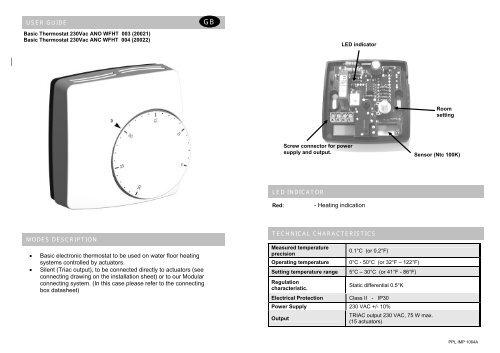
<strong>USER</strong> <strong>GUIDE</strong>GBLED Indicator.Thermostat basic with pilot wire 230Vac ANO WFHT 012 (20121)Thermostat basic with pilot wire 230Vac ANC WFHT 013 (20122)Selectmode.Roomsetting.Optionalexternal sensor(10K at 25°C 3 meters)Screw connector forPower supply,output andclock (pilot wire)LED INDICATORScrew connector forexternal sensor.MODES DESCRIPTIONRed: - Heating indication with internal sensor regulation.Orange: - Heating indication with external sensor regulation.Green: - reduction mode by clock (pilot wire)- Electronic thermostat with night reduction mode for water floorheating systems controlled by actuators.Red blinking:- 0,5 second cycle => Internal sensor failure- 1 second cycle => External sensor failure- External pilot wire for night reduction, equipped with a switch toselect comfort, reduction or clock mode.- Regulating on internal sensor.- Option: Possibility to regulate on external sensor (NTC 10K)The external sensor must be connected without power supply.At power up the thermostat automatically detects the sensor used.(If the external sensor is connected the regulation use this sensor)- Silent (triac output), to be connected directly to actuators (seeconnecting drawing on the installation sheet) or to our Modularconnecting system. (In this case please refer to the connecting boxdatasheet)<strong>TECHNICAL</strong> <strong>CHARACTERISTICS</strong>Measured temperature precisionOperating temperatureSetting temperature rangeRegulation characteristicsElectrical Protection0.1°C (or 0.2°F)0°C - 50°C (or 32°F – 122°F)5°C – 30°C (or 41°F - 86°F)Static differential 0.5°KClass II - IP30Power Supply 230 VAC +/- 10%OutputOptional External sensorTRIAC output 230 VAC, 75 W max.( 15 actuators)NTC (10K Ohms) 3mPPL IMP 1214A
MANUAL DE USUARIOEIndicador LEDTermostato básico con hilo piloto 230Vac ANO WFHT 012 (20121)Termostato básico con hilo piloto 230Vac ANC WFHT 013 (20122)Selector demodoAjuste temp.ambienteBorne para alimentación,salida y reloj (hilo piloto)Borne para el sensorexternoSensor externo opcional(10K at 25°C 3 M)INDICADOR LEDRojo: - Indicación de calefacción con regul. basada en sensor internoNaranja: - Indicación de calefacción con regul. basada en sensor externoVerde: - Modo reducción mediante reloj (hilo piloto)DESCRIPCIÓN DE MODOS- Termostato electrónico con modo de reducción nocturna para sistemasde calefacción por suelo radiante controlados por actuadores.- Hilo piloto externo para reducción nocturna, equipado con uninterruptor para seleccionar el modo confort, reducción o reloj.- Regulación basada en sensor interno.- Opción: Posibilidad de regulación basada en sensor externo (NTC 10K)El sensor externo debe conectarse sin alimentación.Al arrancar, el termostato detecta automáticamente el sensor utilizado.(Si está conectado el sensor externo, la regulación lo utilizará)- Contacto silencioso (TRIAC), conectado directamente a los actuadores(ver esquema de conexiones en hoja de instalación) o a nuestrosistema de conexión modular. (En este caso, consulte la hoja técnicade la caja de conexión.)Rojo parpadeando:- Ciclo de 0,5 segundos => Fallo del sensor interno- Ciclo de 1 segundo => Fallo del sensor externoCARACTERÍSTICAS TÉCNICASPrecisión de la mediciónTemperatura de funcionamientoRango de ajuste de la temperaturaCaracterísticas de la regulaciónProtección eléctrica0.1°C (ó 0.2°F)0°C - 50°C (ó 32°F – 122°F)5°C – 30°C (ó 41°F - 86°F)Diferencial estático 0.5°KClase II - IP30Alimentación 230 VAC +/- 10%SalidaSensor externo opcionalTRIAC 230 VAC, 75 W máx.( 15 actuadores)NTC (10K Ohms) 3m
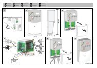
F Installation GB Installation D Installation I Installazione E InstalaciónP instalação NL installatie FIN Asennus SE Installation N Installasjon12~ 1,50 mMin 20 cm360mm44 4 2 1 A/B31mm80mm5Max =>2.5mm²N L230Vac6PPL IMP 1210 B
F Limitation GB Limitation D Begrenzung I Limitazione E LimitaciónP Limitação NL Begrenzing FIN Kalibrointi SE Begränsning N BegrensningXMax 25°CMin < x < MaxMin 15°C15°C20°C15°C20°C10°C10°C25°C25°CMin 15°C Min 15°CMax 25°CF Calibration GB Calibration D Kalibrierung I Calibrazione E CalibraciónP Calibração NL Calibratie FIN Säädön Rajoitus SE Kalibriering N Kalibriering1215 min= 23°C34
<strong>USER</strong> <strong>GUIDE</strong> GB CONFIGURATION SWITCHDual Sensing Thermostat 230Vac ANO WFHT 022 (20221)Dual Sensing Thermostat 230Vac ANC WFHT 023 (20222)1 2 3 4 OffOnNC ActuatorNO ActuatorActuator type 1:static differentialproportionalRegulation mode 2:- Regulation on internal room- Regulation on external probe- Regulation internal room sensorwith lower limit floor on ext. probe- Regulation on internal room sensorwith upper limit floor on ext. probeSensor mode 3&4 :MODES DESCRIPTION- Electronic thermostat with night reduction mode for water floor heatingsystems controlled by actuators.- External pilot wire for night reduction, equipped with a switch to selectcomfort, reduction or clock mode.- Possibility to regulate either the floor or room temperature, or combined(in this case, the floor sensor is used as temperature limiter)- Silent (triac output), to be connected directly to actuators (see connectingdrawing on the installation sheet) or to our Modular connecting system.(In this case please refer to the connecting box datasheet)Screw connector forPower supply,output andclock (pilot wire)LED Indicator.Configurationswitch.Selectmode.Floor limitsetting.Roomsetting.Screw connector forexternal sensor.LED INDICATORRed: - Heating indicationGreen: - reduction mode by clock (pilot wire)Orange: - Heating during reduction mode by clock (pilot wire)Red blinking: - 0.5 second cycle => Internal & external sensor failures- 1 second cycle => Internal sensor failure- 2 seconds cycle => External sensor failure<strong>TECHNICAL</strong> <strong>CHARACTERISTICS</strong>Measured temperatureprecisionOperating temperatureSetting temperature rangeFloor limiting temperaturerangeRegulationcharacteristics0.1°C (or 0.2°F)0°C - 50°C (or 32°F – 122°F)5°C – 30°C (or 41°F - 86°F)10°C – 40°C (or 50°F - 104°F)Proportional band 10min for 2°Kor Static differential 0.5°KElectrical Protection Class II - IP30Power Supply 230 VAC +/- 10%OutputTRIAC output 230 VAC, 75 W max.(15 actuators)External Floor sensor NTC (10K Ohms) 3mSoft version V 1.4xPPL IMP 1024A
MANUAL DE USUARIO E INTERRUPTOR DE CONFIGURACIÓNTermostato “Dual Sensor” 230Vac ANO WFHT 022 (20221)Termostato “Dual Sensor” 230Vac ANC WFHT 023 (20222)1 2 3 4 OffOnActuador NCActuador NOTipo de actuador 1:Diferencial estáticoProporcionalModo regulación 2:- Regulación según sensor interno- Regulación según sonda externa- Regul. según sensor int. con límiteinf. de temp. basado en sonda ext.- Regul. según sensor int. con límitesup. de temp. basado en sonda ext.Modo sensor 3&4 :DESCRIPCIÓN DE MODOS- Termostato electrónico con modo de reducción nocturna para sistemas decalefacción por suelo radiante controlados por actuadores.- Hilo piloto externo para reducción nocturna, equipado con un interruptor paraseleccionar el modo confort, reducción o reloj.- Posibilidad de regular la temperatura ambiente o del suelo, o ambas (en estecaso, el sensor de suelo se usa como limitador de temperatura).- Contacto silencioso (TRIAC), conectado directamente a los actuadores (veresquema de conexiones en hoja de instalación) o a nuestro sistema deconexión modular. (En este caso, consulte la hoja técnica de la caja deconexión.)Interruptor deIndicador LEDconfiguraciónBorne paraalimentación, salida yreloj (hilo piloto)Selector demodoAjuste temp.límite delsueloAjuste temp.ambienteBorne para el sensorexternoINDICADOR LEDRojo:Verde:Naranja:Indicación de calefacciónModo reducción mediante reloj (hilo piloto)Calefacción durante el modo reducción mediante reloj (hilopiloto.Rojo parpad.: - Ciclo de 0,5 segundos => Fallo de los sensores interno y externo- Ciclo de 1 segundo => Fallo del sensor interno- Ciclo de 2 segundos => Fallo del sensor externoCARACTERÍSTICAS TÉCNICASPrecisión de la medición0.1°CTemperatura de funcionamiento 0°C - 50°CRango de ajuste de latemperatura5°C – 30°CRango de temperatura límite delsuelo10°C – 40°CCaracterísticas deregulaciónProtección eléctricaAlimentación 230 VAC +/- 10%Banda proporcional de 10 minutos para2°K o diferencial estático de 0.5°KClase II - IP30SalidaTRIAC 230 VAC, 75 W máx.(15 actuadores)Sensor de suelo externoNTC (10K Ohms) 3mVersión del software V 1.4x
F Installation GB Installation D Installation I Installazione E InstalaciónP instalação NL installatie FIN Asennus SE Installation N Installasjon12~ 1,50 mMin 20 cm360mm431mm80mm5Max => 2.5mm²N L230Vac6PPL IMP 1020 B
F Limitation GB Limitation D Begrenzung I Limitazione E LimitaciónP Limitação NL Begrenzing FIN Kalibrointi SE Begränsning N BegrensningXMax 25°CMin < x < MaxMin 15°C15°C20°C15°C20°C10°C10°C25°C25°CMin 15°C Min 15°CMax 25°CF Calibration GB Calibration D Kalibrierung I Calibrazione E CalibraciónP Calibração NL Calibratie FIN Säädön Rajoitus SE Kalibriering N Kalibriering1215 min= 23°C34
<strong>USER</strong> <strong>GUIDE</strong> GB CONFIGURATION SWITCHDual Sensing public area Thermostat 230Vac ANO WFHT 032 (20321)Dual Sensing public area Thermostat 230Vac ANC WFHT 033 (20322)1 2 3 4onoffNC Actuator offNO Actuator onActuator type 1:static differential offor proportional onRegulation mode 2:- Regulation on internal room- Regulation on external probe- Regulation internal room sensorwith lower limit floor on ext. probe- Regulation on internal room sensorwith upper limit floor on ext. probeSensor mode 3&4 :MODES DESCRIPTION- This thermostat is specially made for public area (school, office ….)- Electronic thermostat with night reduction mode for water floor heatingsystems controlled by actuators.- External pilot wire for night reduction, equipped with an internal switch toselect comfort, reduction or clock mode.- Possibility to regulate either the floor or room temperature, or combined(in this case, the floor sensor is used as temperature limiter)- Silent (triac output), to be connected directly to actuators (see connectingdrawing on the installation sheet) or to our Modular connecting system.(In this case please refer to the connecting box datasheet)ConfigurationLED Indicator.switch.Screw connector forPower supply,output andclock (pilot wire)Selectmode.Floor limitsetting.Roomsetting.Screw connector forexternal sensor.LED INDICATORRed: Heating indicationGreen: reduction mode by clock (pilot wire)Orange: Heating during reduction mode by clock (pilot wire)Red blinking: - 0.5 second cycle => Internal & external sensor failures- 1 second cycle => Internal sensor failure- 2 seconds cycle => External sensor failure<strong>TECHNICAL</strong> <strong>CHARACTERISTICS</strong>Measured temperatureprecisionOperating temperatureSetting temperature rangeFloor limiting temperaturerangeRegulationcharacteristics0.1°C (or 0.2°F)0°C - 50°C (or 32°F – 122°F)5°C – 30°C (or 41°F - 86°F)10°C – 40°C (or 50°F - 104°F)Proportional band 10min for 2°Kor Static differential 0.5°KElectrical ProtectionClass II - IP30Power Supply 230 VAC +/- 10%OutputTRIAC output 230 VAC, 75 W max.( 15 actuators)External Floor sensor NTC (10K Ohms) 3mSoft Version V 1.4xPPL IMP 1094 A
MANUAL DE USUARIO E INTERRUPTOR DE CONFIGURACIÓNTermostato para “Áreas públicas” 230Vac ANO WFHT 032 (20321)Termostato para “Áreas públicas” 230Vac ANC WFHT 033 (20322)1 2 3 4 OffOnActuador NC offActuador NO onTipo de actuador 1:Estática diferencial offo proporcional onModo regulación 2:- Regulación según sensor interno- Regulación según sonda externa- Regul. según sensor int. con límiteinf. de temp. basado en sonda ext.- Regul. según sensor int. con límitesup. de temp. basado en sonda ext.Modo sensor 3&4 :DESCRIPCIÓN DE MODOS- Este termostato está diseñado especialmente para zonas públicas (colegios,oficinas…)- Termostato electrónico con modo de reducción nocturna para sistemas decalefacción por suelo radiante controlados por actuadores.- Hilo piloto externo para reducción nocturna, equipado con un interruptorinterno para seleccionar el modo confort, reducción o reloj.- Posibilidad de regular la temperatura ambiente o del suelo, o ambas (en estecaso, el sensor de suelo se usa como limitador de temperatura).- Contacto silencioso (TRIAC), conectado directamente a los actuadores (veresquema de conexiones en hoja de instalación) o a nuestro sistema deconexión modular. (En este caso, consulte la hoja técnica de la caja deconexión.)Indicador LEDInterruptor deconfiguraciónBorne para alimentación,salida y reloj (hilo piloto)Selector demodoAjuste temp.límite delsueloAjuste temp.ambienteBorne para el sensorexternoINDICADOR LEDRojo: Indicación de calefacciónVerde: Modo reducción mediante reloj (hilo piloto)Naranja: Calefacción durante el modo reducción mediante reloj (hilo pilotoRojo parpad.: - Ciclo de 0,5 segundo => Fallo de los sensores interno y externo- Ciclo de 1 segundo => Fallo del sensor interno- Ciclo de 2 segundos => Fallo del sensor externoCARACTERÍSTICAS TÉCNICASPrecisión de la mediciónTemperatura de funcionamientoRango de ajuste de latemperaturaRango de temperatura límite delsueloCaracterísticas deregulaciónProtección eléctrica0.1°C (ó 0.2°F)0°C - 50°C (ó 32°F – 122°F)5°C – 30°C (ó 41°F - 86°F)10°C – 40°C (ó 50°F - 104°F)Alimentación 230 VAC +/- 10%Banda proporcional de 10 minutos para2°K o diferencial estático de 0.5°KClase II - IP30SalidaTRIAC de 230 VAC, 75 W máx.( 15 actuadores)Sensor de suelo externoNTC (10K Ohms) 3mVersión del software V 1.4x
F Installation GB Installation D Installation I Installazione E InstalaciónP instalação NL installatie FIN Asennus SE Installation N Installasjon12~Min 20cm3460mm31mm80mmMax => 2.5mm²N L5230Vac6PPL IMP 1090 B
<strong>USER</strong> <strong>GUIDE</strong> GB INSTALLATION PARAMETERS MENUSDual Sensing Digital Thermostat 230Vac WFHT 041 (20425)Press the OK key during 5 seconds, Then use + or - keys to select the installation parameter to be adjusted.Press OK to toggle the parameter setting or edit the value. If the value starts to blink you can use + / - keys to adjust thisvalue. Press + & - keys at the same time to reset this value to the factory default value. Once you have adjusted thevalue press OK to validate this parameter value.When you have finished, use + / - keys to go to ‘End’ display and then press OK key to exit installation parameter menu.MODES DESCRIPTION- Electronic thermostat with LCD display mode for water floor heatingsystems controlled by actuators.- External pilot wire for night reduction.- Three Functioning modes: Comfort, reduction or Clock mode.- Possibility to regulate either the floor or room temperature, or combined(in this case, the floor sensor is used as temperature limiter)- Silent (triac output), to be connected directly to actuators (see connectingdrawing on the installation sheet) or to our Modular connecting system.(In this case please refer to the connecting box datasheet)Use OK key to change the mode in the Operating mode menuCOMFORT operating mode:Force comfort temperature operationindefinitely.By pressing +/- keys the comforttemperature starts to blink and can beadjusted.The measured temperaturereappears after a few seconds.OFF mode:Use this mode if your Heatinginstallation needs to be turned OFF.The display is blank.(Careful in this mode your installationcan freeze)Parameters are saved.REDUCED operating mode:Force reduced temperature operationindefinitely.By pressing +/- keys the comforttemperature starts to blink and can beadjusted.The measured temperaturereappears after a few seconds.External PILOT WIRE mode:The Thermostat will follow the externalPILOT WIRE signal.Blinking for indicate a comfort signal.Blinking for indicate a reduced signal.J0 : °C / °F temperature display selectionJ1 : “Hot” / “Cold” regulation mode. Select Hot for a Heater system, select Cold for a Cooling systemCy : Proportional Integral regulation time cycle value in minutes (default: 15 minutes cycle)bp : Proportional Integral regulation band amplitude value in degrees °C/°F (default: 2.0°C/3.6°F)J4: “NC” or “NO” Normally closed or normally open actuators selection.J5 : Select “PMP” to perform an 1 minute exercise everyday (if installation inactive during a day)J6 : Air or Floor temperature regulation selection. (if no Floor sensor, regulation will use Air sensor)J7 : “rEG” (Proportional Integral) or “HYs” (0.3°K Hysteresis) regulation type selectionCp : compensation value in °C/°F (default: 2.0°C/3.6°F) this parameter must be adjusted by a professional.Ao : Air sensor offset adjustment (default: no offset). Display measured Air sensor valueFo : Floor sensor offset adjustment (default: no offset). Display measured Floor sensor valueFL : Floor temperature LOW limitation (default: 5°C/41°F), effective only if floor sensor presentFH : Floor temperature HIGH limitation (default: 28°C/82°F) , effective only if floor sensor presentCLr : Press OK key during 5s to reset all the WFHT LCD parameters to factory defaultsEnd : Press OK key to exit installation parameter menu and return to normal operation* (Default parameters are underlined.)DISPLAY1: Operating mode menu.2: Heating indication.3: Cooling indication.4: If symbol is displayed the measured temperatureis shown (position 5)5: Measured temperature or set temperature.6: °C or °F indication.7: Title for installation Parameters (J0,CLr…)<strong>TECHNICAL</strong> <strong>CHARACTERISTICS</strong>Measured temperature precisionOperating temperatureSetting temperature rangeRegulation characteristicsElectrical Protection0.1°C (or 0.2°F)0°C - 50°C (or 32°F – 122°F)5°C - 37°C by 0.5°C step(or 41°F - 99°F by 0.5°F step)Proportional Integral regulation (adjustable see installationmenu) Cycle: 15 minutes orStatic differential 0.3°KAnti-short cycle: 3min in OFF, 2min in ON.Class II - IP30Power Supply 230 VAC +/- 10%OutputExternal Floor sensor1234TRIAC output 230 VAC, 75 W max.(15 actuators)NTC (10K Ohms) 3m765PPL IMP 1114A
MANUAL DE USUARIO E PARÁMETROS DE INSTALACIÓNTermostato digital “Dual Sensor” 230Vac WFHT 041 (20425)Pulse la tecla OK durante 5 segundos. A continuación, utilice las teclas + ó – para seleccionar el parámetro a ajustar.Pulse OK para alternar entre ajuste del parámetro o edición del valor. Si el valor comienza a parpadear, puede utilizarlas teclas + / - para ajustarlo. Pulse las teclas + y - a la vez para devolver este valor al ajuste predeterminado de fábrica.Una vez haya ajustado el valor, pulse OK para validarlo.Cuando haya finalizado, utilice las teclas + / - para ir a la visualización ‘End’, y luego pulse OK para salir del menúparámetros de instalación.DESCRIPCIÓN DE MODOS- Termostato electrónico con display LCD para sistemas de calefaccióny/o refrescamiento por suelo radiante controlados por actuadores.- Hilo piloto externo para reducción nocturna.- Tres modos de funcionamiento: confort, reducción o reloj- Posibilidad de regular la temperatura ambiente o del suelo, o ambas (eneste caso, el sensor de suelo se usa como limitador de temperatura).- Termostato silencioso (TRIAC), conectado directamente a losactuadores (ver esquema de conexiones en hoja de instalación) o anuestro sistema de conexión modular. (En este caso, consulte la hojatécnica de la caja de conexión.)Utilice la tecla OK para cambiar el modo en el menú de modos de funcionamientoJ0 : Selección de visualización de temperatura en °C / °F.J1 : Modo de regulación «Hot» / «Cold». Seleccione «Hot» para calefacción, y «Cold» para frío.Cy : Valor del ciclo de regulación proporcional integral en minutos. (por defecto: ciclo de 15 minutos)bp : Valor de la amplitud de la banda de regulación proporcional integral en °C / °F (por defecto: 2.0°C / 3.6°F)J4: Selección de actuadores: « NC » (normalmente cerrado) o « NO » (normalmente abierto).J5 : Seleccione «PMP» para realizar un ciclo de comprobación de 1 minuto todos los días. (Si la instalación estáinactiva durante un día)J6 : Selección de la regulación de temperatura del aire o del suelo. (Si no hay sensor de suelo, la regulaciónutilizará el sensor ambiente)J7 : Selección del tipo de regulación : « rEG » (proporcional integral) o « Hys » (Histéresis 0.3°K)Cp : Valor de compensación en °C/°F (Predef.: 2.0°C/3.6°F). Este parámetro debe ser ajustado por un profesionalAo : Calibrado del sensor ambiente (por defecto: sin desviación). Visualización del valor medidoFo : Calibrado del sensor de suelo (por defecto: sin desviación). Visualización del valor medidoFL : Límite inferior (LOW) de la temp. del suelo (por defecto: 5°C / 41°F), sólo efectivo si existe sensor de sueloFH : Límite sup. (HIGH) de la temp. del suelo (por defecto: 28°C / 82°F), sólo efectivo si existe sensor de sueloCLr : Pulse OK durante 5 seg. para devolver todos los parámetros WFHT LCD a la configuración de fábricaEnd : Pulse la tecla OK para salir del menú de parámetros de instalación y volver al funcionamiento normal* (Los parámetros por defecto están subrayados.)DISPLAY1: Modo de funcionamiento2: Indicador de calefacción3: Indicador de frío4: Si está encendido, 5 muestra la temperatura medida5: Temperatura medida o ajustada6: Indicador °C o °F7: Título de los parámetros de instalación (rF, J0,CLr…)1234765Modo CONFORT:El termostato mantiene latemperatura de confortindefinidamente.Al pulsar las teclas +/- la temperaturade confort comienza a parpadear ypuede ser ajustada.La temperatura medida vuelve aaparecer después de unos segundos.Modo APAGADO:Utilice este modo si necesita apagarsu calefacción. El display quedará enblanco. (Tenga cuidado al utilizareste modo, su instalación podríacongelarse)Los parámetros quedan guardados.Modo REDUCIDO:El termostato mantiene una temperaturareducida indefinidamente.Al pulsar las teclas +/- la temperatura de confortcomienza a parpadear y puede ser ajustadaLa temperatura medida vuelve a aparecerdespués de unos segundos.Modo HILO PILOTO externo:El termostato obedecerá la señal del HILOPILOTO externo.Parpadeando para indicar una señal deconfort.Parpadeando para indicar una señal dereducción.CARACTERÍSTICAS TÉCNICASPrecisión de la mediciónTemperatura de funcionamientoRango de ajuste de latemperaturaCaracterísticas deregulaciónProtección eléctrica0.1°C (ó 0.2°F)0°C - 50°C (ó 32°F – 122°F)5°C - 37°C en incrementos de 0.5°C(ó 41°F - 99°F en incrementos de 0.5°F)Regulación proporcional integral (ajustable, véase menú deinstalación) ciclo: 15 minutos oDiferencial estático de 0.3°KCiclo anti-corte: 3min en OFF, 2min en ON.Clase II - IP30Alimentación 230 VAC +/- 10%SalidaSensor de suelo externoTRIAC de 230 VAC, 75 W máx.(15 actuadores)NTC (10K Ohms) 3m
DInstallationGB InstallationF InstallationEInstalaciónIInstallazioneP instalação NL installatie FIN Asennus SE Installation N Installasjon12~Min 20cm3460mm4 4 2 1A/B31mm80mmNL5Max =>1.5mm²230Vac6PPL IMP 1110 B
Conector de tornillopara bomba yaccesoriosIndicador LED dela zonaMANUAL DE USUARIO EMaster 4 zonas 230VAC para actuadores NC (normalmente cerrados)CARACTERÍSTICAS TÉCNICASConector de tornillopara alimentaciónAlimentación paratermostato yactuadores de 1 zonaTemperatura de funcionamiento 0°C - 50°CProtecciónClase I - IP20COMBINACIONES POSIBLES (4, 8, 10 zonas)AlimentaciónSalidas230 VAC +/- 10% 50HzBomba y accesorios:Relé => 2 contactos libres 8A 250VacZonas:4 zonas independientes => la potencia máximade salida de cada zona depende del termostatoconectado en la misma.MASTER 4 ZONES + TEMPORIZADORFUNCIÓN y DESCRIPCIÓNMASTER 4 ZONES + ESCLAVO 4 ZONES + TEMPORIZADOREl MASTER 4 zonas es un módulo de conexión con lógica de bomba incorporada.Todas las conexiones eléctricas principales para el sistema de calefacción porsuelo radiante están realizadas de antemano. Esta caja puede adaptarse a un raílDIN o montarse directamente en la pared. (El montaje en raíl DIN permite añadirun módulo ESCLAVO o un TEMPORIZADOR). Conecta los termostatos deambiente con sus actuadores correspondientes. El estado de las zonas quedaindicado mediante LEDs individuales. Usando los terminales A y B, el hilo pilotode los termostatos puede ser controlado por un TEMPORIZADOR externo. Tanpronto tenemos una demanda de calor en una zona, se activa un relé con 2contactos libres de potencial (bomba, caldera u otra posible conexión).MASTER 4 ZONES + ESCLAVO 6 ZONES + TEMPORIZADORINDICADOR LEDVerde:- Indicación de calefacción (circulación de agua en esta zona)PPL IMP 2014A
EJEMPLO DE CABLEADODe 0,5 a 2.5mm²Termostato4 4 2 1 A/B230VACNC230VACNC
Screw connector forpump and accessoriesLED indicatorzone<strong>USER</strong> <strong>GUIDE</strong>Master 4 zones 230VAC for NC actuators (Normaly Closed)GB<strong>TECHNICAL</strong> <strong>CHARACTERISTICS</strong>Screw connector forpower supplyPOSSIBLES COMBINATIONS (4, 8, 10 zones)Supply for thermostatand actuators for 1zoneOperating temperature 0°C - 50°CProtectionClass I - IP20Power supply 230 VAC +/- 10%OutputPump & accessories:Relay => 2 free contact 8A 250VacZones:4 independent zones => the maximum outputpower of each zones depends on thermostatconnecting on this zone. The maximum currentfor all connected actuators is 2.5AMASTER 4 ZONES + TIMERMASTER 4 ZONES + SLAVE 4 ZONES + TIMERFUNCTION and DESCRIPTIONThe MASTER with 4 zones is a wiring module with built in pump logic. All themain electrical connections for water floor heating system are existing. Thisbox can be adapted either on a DIN rail or directly on a wall. (the DIN railmounting permit to add with facility a SLAVE module or TIMER). It connectsroom thermostats to their corresponding actuators. The state of the zones areindicated by individual LEDs. By using terminal A and B, the pilot wire ofthermostats can be controlled by an external TIMER. As soon as we have aheat demand from one zone a relay with 2 potential-free contacts is switch on(pump, boiler or other possible connection).LED INDICATORMASTER 4 ZONES + SLAVE 6 ZONES + TIMERGreen:- Heating indication (water circulation on this zone)PPL IMP 2015A
WIRING EXAMPLE0,5 to 2.5mm² 4 4 2 1 A/B230VACNC230VACNC
DInstallationGB InstallationF InstallationEInstalaciónIInstallazioneP instalação NL installatie FIN Asennus SE Installation N Installasjon123160 mm123 mm31mm88 mm78 mm456PPL IMP 2010A
Indicador LED dela zonaMANUAL DE USUARIO EMaster 6 zonas 230VAC para actuadores NC (normalmente cerrados)CARACTERÍSTICAS TÉCNICASConector de tornillopara bomba yaccesoriosConector de tornillopara alimentaciónAlimentación paratermostato yactuadores de 1 zonaTemperatura de funcionamiento 0°C - 50°CProtecciónClase I - IP20COMBINACIONES POSIBLES (6, 10, 12 zonas)AlimentaciónSalidas230 VAC +/- 10% 50HzBomba y accesorios:Relé => 2 contactos libres 8A 250VacZonas:6 zonas independientes => la potencia máximade salida de cada zona depende del termostatoconectado en la misma.MASTER 6 ZONAS + TEMPORIZADORFUNCIÓN y DESCRIPCIÓNMASTER 6 ZONAS + ESCLAVO 4 ZONAS + TEMPORIZADOREl MASTER 6 zonas es un módulo de conexión con lógica de bomba incorporada.Todas las conexiones eléctricas principales para el sistema de calefacción porsuelo radiante están realizadas de antemano. Esta caja puede adaptarse a un raílDIN o montarse directamente en la pared. (El montaje en raíl DIN permite añadirun módulo ESCLAVO o un TEMPORIZADOR). Conecta los termostatos deambiente con sus actuadores correspondientes. El estado de las zonas quedaindicado mediante LEDs individuales. Usando los terminales A y B, el hilo pilotode los termostatos puede ser controlado por un TEMPORIZADOR externo. Tanpronto tenemos una demanda de calor en una zona, se activa un relé con 2contactos libres de potencial (bomba, caldera u otra posible conexión).INDICADOR LEDMASTER 6 ZONAS + ESCLAVO 6 ZONAS + TEMPORIZADORVerde:- Indicación de calefacción (circulación de agua en esta zona)PPL IMP 2034A
EJEMPLO DE CABLEADODe 0,5 a 2.5mm²4 4 2 1 A/B230VACNC230VACNC
LED indicatorzone<strong>USER</strong> <strong>GUIDE</strong>Master 6 zones 230VAC for NC actuators (normaly closed)GB<strong>TECHNICAL</strong> <strong>CHARACTERISTICS</strong>Screw connector for Screw connector forpump and accessories power supplySupply for thermostatand actuators for 1zoneOperating temperature 0°C - 50°CProtectionClass I - IP20POSSIBLES COMBINATIONS (6, 10, 12 zones)Power supply 230 VAC +/- 10%Pump & accessories:Relay => 2 free contact 8A 250VacZones:Output6 independent zones => the maximum outputpower of each zones depends on thermostatconnecting on this zone.MASTER 6 ZONES + TIMERMASTER 6 ZONES + SLAVE 4 ZONES + TIMERFUNCTION and DESCRIPTIONThe MASTER with 6 zones is a wiring module with built in pump logic. All themain electrical connections for water floor heating system are existing. Thisbox can be adapted either on a DIN rail or directly on a wall. (the DIN railmounting permit to add with facility a SLAVE module or TIMER). It connectsroom thermostats to their corresponding actuators. The state of the zones areindicated by individual LEDs. By using terminal A and B, the pilot wire ofthermostats can be controlled by an external TIMER. As soon as we have aheat demand from one zone a relay with 2 potential-free contacts is switch on(pump, boiler or other possible connection).LED INDICATORMASTER 6 ZONES + SLAVE 6 ZONES + TIMERGreen:- Heating indication (water circulation on this zone)PPL IMP 2035A
0,5 to 2.5mm² 4 4 2 1 A/B230VACNC230VACNC
DInstallationGB InstallationF InstallationEInstalaciónIInstallazioneP instalação NL installatie FIN Asennus SE Installation N Installasjon123225 mm187 mm31mm88 mm78 mm456PPL IMP 2030A
Indicador LED dela zonaMANUAL DE USUARIOEsclavo 4 o 6 zonas 230VAC para actuadores NC (normalmente cerrados)EMASTERAlimentación paratermostato yactuadores de 1 zonaCOMBINACIONES POSIBLES (8, 10, 12 zonas)CARACTERÍSTICAS TÉCNICASTemperatura de funcionamiento 0°C - 50°CMASTER 4 ZONES + ESCLAVO 4 ZONES + TEMPORIZADORProtecciónAlimentaciónSalidasClase I - IP20230 VAC +/- 10% 50HzZonas:4 o 6 zonas independientes => la potenciamáxima de salida de cada zona depende deltermostato conectado en la misma.La corriente de salida máxima para el conjuntode las actuadores conectadas es 2,5A.MASTER 4 ZONES + ESCLAVO 6 ZONES + TEMPORIZADORFUNCIÓN y DESCRIPCIÓNMASTER 6 ZONES + ESCLAVO 4 ZONES + TEMPORIZADOREl ESCLAVO 4 o 6 zonas es un caja de connexiones adicional quedebe ser reunido con un mòdulo MASTER.El mòdulo ESCLAVO permite de anãdir 1 termostato y 4 actuadorespor zona supplementaria. El cuento maximò de actuadores que puedeconectar depende de la potencia total conectada a sa dispositivo.INDICADOR LEDMASTER 6 ZONES + ESCLAVO 4 ZONES + TEMPORIZADORVerde:- Indicación de calefacción (circulación de agua en esta zona)PPL IMP 2024A
EJEMPLO DE CABLEADODe 0,5 a 2.5mm²4 4 2 1 A/B230VACNC230VACNC
WIRING EXAMPLE0,5 to 2.5mm² 4 4 2 1 A/B230VACNC230VACNC
MANUAL DE USUARIOEMenú PROGRAMA:Con las teclas +/- seleccione el canal ChA o ChB a programar, y después pulseOK para validar.Pulse +/- para cambiarel programaUtilice para verlos otros días delprograma.Muestra el programadiarioSi selecciona un programa preestablecido P1 a P9 y pulsa OK, este programapasará al modo .CARACTERÍSTICAS• Programación de 7 días.• 2 canales: A y B• 9 programas preajustados.• 1 programa de usuario por canal• Visualización gráfica delprograma.DISPLAY• Funcionamiento automático omanual.• Bloqueo del teclado (proteccióninfantil)• Memoria de la hora y losparámetros en caso de fallo decorriente.1Descripción de los programas preajustadosP1 Mañana, noche y fin de semanaP6 Mañana, tarde y fin de semanaP2 Mañana, mediodía, tarde y f. semanaP7 7h - 19h (oficina)P3 Día y fin de semanaP8 8h - 19h sábado (comercio)P4 Noche y fin de semanaP9 Fin de semana (2ª residencia)P5 Mañana, noche (cuarto de baño)También puede seleccionar un programa de usuario U1 para el Canal A y U2para el Canal B.EDICIÓN DEL PROGRAMA DE USUARIOLa tecla + ajusta una temperaturaen la hora actual parpadeanteLa tecla – ajusta una temperaturaen la hora actual parpadeanteHora del cursorCon las teclas puede desplazar la posición del cursor parpadeante en eldía y modificar o corregir fácilmente el programa.Cuando el día sea correcto, pulse OK para validarlo y pase al siguiente día. Alvalidar el día 7 volverá automáticamente al menú.Día1: Modo de funcionamiento2: Días de la semana3: Hora4: Gráfico del programa5: Canal A o B.523Ahora, al elegir el modo automático , el Temporizador seguirá losprogramas elegidos para los Canales A y B.FUNCIONES ESPECIALESDESCRIPCIÓN DE MODOSUtilice las teclas para cambiar el modo en el menú de modos defuncionamiento.Menú ajuste de RELOJUtilice este menú para ajustar el reloj delTemporizador a la hora actual.Use +/ - paraajustar los minutosUse +/ - paraajustar las horasLuego use +/ - paraAjustar el díaPulse OKPulse OKPulse OKModo AUTOMÁTICOEl Temporizador sigue automáticamenteel programa seleccionado según la horaactual.Modo manual REDUCIDOFuerza una temperatura reducidaindefinidamente en los 2 canalesModo manual CONFORTFuerza una temperatura confortindefinidamente en los 2 canalesNOTA IMPORTANTE:Para que sus termostatos ejecuten los modos , , delTEMPORIZADOR, ajústelos en la posición .488 mmFunción BLOQUEO DE TECLADO:Esta función impide cualquier modificación o cambio de los parámetros.En los modos de funcionamiento , , , debe mantener presionada latecla OK y pulsar de forma simultánea las teclas + ó – para bloquear (desbloquear ( ) el teclado.CARACTERÍSTICAS TÉCNICASTensión de funcionamiento 230VAC +- 10%Temperatura de funcionamiento 0 - 50 °C (ó 32 – 122 °F)Protección eléctricaDIMENSIONES78 mmIP30) o123 mm160 mm62 mmMASTER 6 ZONAS ó 4 ZONASTEMPORIZADORPPL IMP 2044A
<strong>USER</strong> <strong>GUIDE</strong>GBPROGRAM menu :By pressing +/- keys select the channel ChA or ChB to program, then validatewith OK.Then press +/ - tochange the programUse to see theother days in the programShows the daily program<strong>CHARACTERISTICS</strong>• 7 days programming• 2 Channels A and B• 9 Built-in programs• 1 user program per channel• Program graphic display• Automatic or Manual operation• Keypad lock function (childsafety)• Hours and parameters are savedin case of power cut.If you select a built-in program P1 to P9 and press OK this program will be followed inmode.Built-in programs descriptionP1: Morning, Evening & Week-end P6: Morning, Afternoon & Week-endP2: Morning, Midday, Evening & Week-end P7: 7h - 19h (Office)P3: Day & Week-end P8: 8h - 19h Saturday (Shop)P4: Evening & Week-end P9: Week-end (Secondary House)P5: Morning, Evening (bathroom)You can also select a user program U1 for the Channel A and U2 for theChannel B.<strong>USER</strong> PROGRAM EDITIONHour of the cursorThe + key sets temperature at thecurrent blinking program hourThe – key sets temperature at thecurrent blinking program hourDayDISPLAY1 : Operating mode menu2 : Days of the week3 : Time4 : Program graphic5 : Channel A or B5123Use keys to slide the blinking cursor position in the day and modify orcorrect easily the program.When the displayed day is correct press OK to save it and then you jump to thefollowing day. When you press OK on day 7 you return to the top menuNow once automatic operating mode is selected, the Timer will follow forthe Channels A and B the desired programs.SPECIAL FUNCTIONSMODES DESCRIPTIONUse the keys in order to change the mode in the operating modemenu.Set CLOCK MenuUse this menu to adjust the Timer clockto the actual time.Use +/ - toadjust the minutesPress OKUse +/ - toadjust the hoursPress OK4Manual REDUCED operating modeForce reduced temperature operationindefinitely on the 2 Channel.Manual COMFORT operating modeForce comfort temperature operationindefinitely on the 2 Channels.KEYPAD LOCK Function :Function to prevent any modifications or changes of the parameters.In , , ,operating modes you should maintain the OK key pressed andpress simultaneously on the + or – key to lock ( ) or unlock ( ) thekeypad.<strong>TECHNICAL</strong> <strong>CHARACTERISTICS</strong>Operating voltage 230VAC +- 10%Operating temperature 0 - 50 °C (oder 32 – 122 °F)Electrical protectionIP30Them use +/ - toadjust the dayPress OKDIMENSIONSAUTOMATIC operating modeThe Timer follows automatically theselected program according to theactual time.IMORTANT NOTE:In order to control , , your thermostats with the TIMER,please put your thermostat in position.88 mm78 mm123 mm160 mm62 mmMASTER 6 ZONES or 4 ZONESTIMER