Manual MCU 8000(9-11-11) - Fagor Electrónica
Manual MCU 8000(9-11-11) - Fagor Electrónica
Manual MCU 8000(9-11-11) - Fagor Electrónica

Create successful ePaper yourself
Turn your PDF publications into a flip-book with our unique Google optimized e-Paper software.
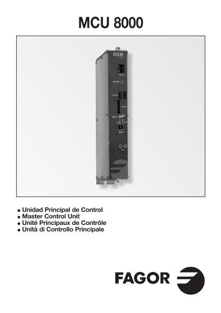
<strong>MCU</strong> <strong>8000</strong>● Unidad Principal de Control● Master Control Unit● Unité Principaux de Contrôle● Unità di Controllo PrincipaleATV
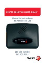
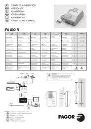
142356724416917935CONTROLES1. Bus de comunicacionesy control2. Bus de comunicacionesy control con otros racks3. Bus de alimentación4. Led de comunicaciones5. Led de control de estado6. Puerto USB para PC local7. V Test fuente alimentaciónCOMMANDES1. Bus de communicationet commanda2. Communications et busde contrôle pour lesautres racks3. Bus d’alimentation4. LED de communication5. LED de contrôle d’état6. Port USB pour PC local7. Test de V alimentationCONTROLS1. Communication andcontrol bus2. Communications andcontrol bus for other racks3. Supply bus4. Communication LED5. Status control LED6. USB port for local PC7. V test power supplyCONTROLLI1. Bus di comunicazionee control2. Comunicazioni e bus dicontrollo per altri rack3. Bus di alimentazione4. Led di comunicazione5. Led di controllo di stato6. Porta USB per PC locale7. V test di alimentazione■ Características principalesCaracterístiques principalesMain specificationsCaratteristiche principaliE F UK I <strong>MCU</strong> <strong>8000</strong>Comunicaciones Communications Communications ComunicazioniLocal PC : USB Device CDC12MbpsBus Comms: CAN 500kbps protocolLED Status LED Status Status LED LED StatusOFF: DC UnplugedGREEN: OKRED: ErrorLEDCommunicacionesLEDCommunicationsCommunicationsLEDLEDComunicazioniOFF: not dataBlinking: comunications dataTemperatura defuncionamientoTempérature defonctionnementOperatingtemperatureTemperatura difunzionamento0 ÷ 45 ºCConsumo Puissance absorbée Power drawn Potenza assorbita 1,5 W2
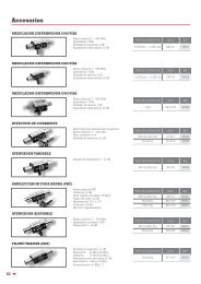
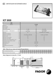
■ EJEMPLO DE APLICACIÓNEXEMPLE D’APPLICATIONAPPLICATION EXAMPLEESEMPIO DI APPLICAZIONEHousing mounting2 14 <strong>11</strong>31234SHASTTSTTSTTSTTSM<strong>MCU</strong>SPS6 5 4 3 2 1765Nº E F UK I Housing Rack 19”1 Transmodulador Transmodulateur DVB S/S2 - DVB T TransmodulatoreDVB S/S2 - DVB T DVB S/S2 - DVB T Transmodulator DVB S/S2 - DVB T08280 / 082812 Amplificador SHA <strong>8000</strong> Amplificateur SHA <strong>8000</strong> SHA <strong>8000</strong> amplifier Amplificatore SHA <strong>8000</strong> 35083Amplificador SAC <strong>8000</strong> Amplificateur SAC <strong>8000</strong> SAC <strong>8000</strong> amplifier Amplificatore SAC <strong>8000</strong> 350813 Bus de alimentación Bus d’alimentation Supply bus Bus di alimentazione 838074 Fuente de alimentación SPS Alimentation SPS Power supply SPS Fonte di Alimentazione SPS 6<strong>8000</strong>5 Carga F, 75 Ω Charge F, 75 Ω F load, 75 Ω Carico F, 75 Ω 840<strong>11</strong>6 Puente RF Pont RF RF bridge Ponte RF 83814– Unidad de control UCF 300 Unité de contrôle UCF 300 UCF 300 control unit Unitá di controlo UCF 300 85<strong>11</strong>57 Bastidor pared Châssis mural Wall frame Telaio a muro 83805 –8 Bastidor Rack 19” 6U Châssis Panier 19” 6U 19” 6U rack frame Telaio Rack 19” 6U – 838009 Carátula adaptación Façade adaptation 19” source adaptation Copertina adattamentofuente 19” alimentation 19” front panel fonte 19”– 8380410 Carátula adaptación Façade adaptation 19” module adaptation Copertina adattamentomódulo 19” module 19” front panel modulo 19”– 83802– Cofre con bastidor Coffre avec châssis Howsing with frame Cassetta con telaioy aireación et aération and fan e ventilazione83806 –– Unidad de Unité d’aération Rack ventilation Unità di ventilazioneaireación Rack Panier unit Rack– 8380<strong>11</strong>1 Ventilador VNT 800 para Ventilateur VNT 800 pour Fan VNT 800 for Wall Ventilazione VNT 800 perBastidor BST 807 Châssis mural BST 807 frame BST 807 panello BST 80783818 –12 Unidad de control Unité de contrôle MDU <strong>8000</strong> Unità di<strong>MCU</strong> <strong>8000</strong> <strong>MCU</strong> <strong>8000</strong> Control Unit controllo <strong>MCU</strong>85<strong>11</strong>013 Bus de comunicaciones Bus du communications Communications Bus di comunicazioney control et contrôle and control bus e control838<strong>11</strong>14 Carga USB Charge USB USB Load Crico USB 838133
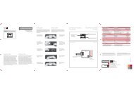
E■ DESCRIPCIÓN● Unidad de Control para programación y gestión del sistemaSCM <strong>8000</strong>.● Es el dispositivo de comunicación entre los módulos de lacabecera SCM <strong>8000</strong> y el ordenador personal PC.● Permite realizar las funciones de:o Programación y monitorización de los módulos de lacabecera SCM <strong>8000</strong> desde el PC.o Detección, registro y gestión de las alarmas que seproduzcan.o Actualización del firmware de los equipos.■ INSTALACIÓN Y PUESTA EN MARCHA●●●●●●●●- Las conexiones y desconexiones de los módulos serealizarán con la fuente de alimentación desconectadade la red.Sujetar los módulos en el bastidor según el orden indicadoen el ejemplo de aplicación.La unidad <strong>MCU</strong> <strong>8000</strong> se posiciona a la izquierda de lafuente de alimentación SPS <strong>8000</strong>.Conectar el bus de alimentación BA 807 Ref. 83807 entrelos módulos y la Fuente de alimentación.Conectar el cable accesorio incluido con el equipo desdeel conector V test de la SPS <strong>8000</strong> al conector V test de la<strong>MCU</strong> <strong>8000</strong>.Conectar los buses de comunicaciones y control(Ref. 838<strong>11</strong>) entre la <strong>MCU</strong>-<strong>8000</strong> y los equipos.Conectar una carga CU 120 en el módulo final del conjuntoa la izquierda de la instalación.Conmutador ADDRESS: los equipos a controlar debentener una dirección diferente entre ellos.Se recomienda colocar el conmutador Address endirecciones crecientes de derecha a izquierda (el primeroa la izquierda de la <strong>MCU</strong>-<strong>8000</strong> en la dirección 1,el siguiente en la dirección 2…). Esta direcciónse corresponde con la imagen de la cabecera que sevisualiza en el PC.Conectar la fuente de alimentación a la red eléctrica.La unidad de control realiza un chequeo de los equiposde la cabecera. Se comunica con ellos, incluyéndolos ensu base de datos y posteriormente realiza su seguimiento.El led de comunicaciones COMM lucirá en verdey parpadeará cuando haya transferencia de datos.■ ACCESO A LA CABECERA VIA PC LOCAL● Para acceder a la cabecera es necesario realizar lossiguientes pasos:● Instalar el programa de PC correspondiente a laSerie <strong>8000</strong>: Interface de Usuario.● Conectar el cable USB B al conector PC de la<strong>MCU</strong> <strong>8000</strong> y el conector USB A al PC.● Al conectar el cable USB, el PC solicita la instalación deldriver correspondiente. Una vez instalado se reconoce la<strong>MCU</strong> <strong>8000</strong> y se encuentra preparada para ser utilizada.● En el programa de PC, pulsando el botón de Conectar seestablece la conexión entre el PC y la <strong>MCU</strong> <strong>8000</strong>.■ FUNCIONES DE LOS LEDS <strong>MCU</strong> <strong>8000</strong>Led de estadoSTATUSLed comunicacionesCOMMApagado: no alimentadoVerde: okRojo: error en equipo o fuente dealimentación conectada por VtestApagado: no hay comunicacionesParpadeo verde: hay comunicaciones4
■ DESCRIPTION● Unité de contrôle de programmation et gestion du systèmeSCM <strong>8000</strong>.● Il s'agit du dispositif de communication entre les modulesde la tête SCM <strong>8000</strong> et le PC.● Il permet de réaliser les fonctions suivantes :o Programmation et suivi des modules de la têteSCM <strong>8000</strong> depuis le PC.o Détection, enregistrement et gestion des alarmes quise produisent.o Actualisation du firmware des appareils.■ ACCÈS À LA TÊTE VIA PC LOCAL● Pour accéder à la tête, suivez les indications suivantes :● Installez le programme du PC correspondant à laSérie <strong>8000</strong> : Interface d'utilisateur.● Connectez le câble USB B au connecteur PC de la<strong>MCU</strong> <strong>8000</strong> et le connecteur USB A au PC.● En connectant le câble USB, le PC demandera l'installationdu driver correspondant. Une fois installé, la <strong>MCU</strong> <strong>8000</strong>sera reconnue et prête à être utilisée.● Sur le programme du PC, appuyez sur le bouton Connecterpour établir la connexion entre le PC et la <strong>MCU</strong> <strong>8000</strong>.■ INSTALLATION ET MISE EN MARCHE●●●●●●●●- Pour la réalisation des connexions et déconnectionsdes modules, la source d'alimentation devra êtredéconnectée du réseau.Fixer les modules sur le châssis suivant l'ordre indiqué surl'exemple d'application.L'unité <strong>MCU</strong> <strong>8000</strong> est positionnée à gauche de la sourced'alimentation SPS <strong>8000</strong>.Connectez le bus d'alimentation BA 807 Réf. 83807 entreles modules et la source d'alimentation.Connectez le câble accessoire fourni avec l'appareil,du connecteur V test de la SPS <strong>8000</strong> au connecteurV test de la <strong>MCU</strong> <strong>8000</strong>.Connectez les bus de communication et de contrôle(Ref. 838<strong>11</strong>) entre la <strong>MCU</strong>-<strong>8000</strong> et les appareils.Connectez une charge CU 120 sur le module final del'ensemble à gauche de l'installation.Conmutador ADDRESS : les appareils à contrôler doiventposséder une adresse différente les uns des autres.Il est recommandé de placer la conmutador Address paradresses croissantes de droite à gauche (la première àgauche de la <strong>MCU</strong>-<strong>8000</strong> à l'adresse 1, la suivante àl'adresse 2…). Cette adresse correspond à l'image de latête visualisée sur le PC.Connectez la source d'alimentation au courant électrique.L'unité de contrôle réalise une vérification des appareilsde la tête. Elle communique avec eux en les incluant sur sabase de données pour ensuite réaliser un suivi. Le led decommunication COMM passera au vert et clignoteralors du transfert de données.F■ FONCTIONS DES LEDS <strong>MCU</strong> <strong>8000</strong>Led d'étatSTATUSLed communicationCOMMÉteint : non alimentéVert : okRouge: erreur sur l'appareil ou sur la sourced'alimentation connectée par V testÉteint : absence de communicationsClignotement vert : existence decommunications5
UK■ DESCRIPTION● Control Unit for programming and managing the SCM <strong>8000</strong>system.● It is the communications device between the SCM <strong>8000</strong>control unit modules and the PC.● It enables performing the following functions:o Programming and monitoring of the SCM <strong>8000</strong> controlunit modules from the PC.o Detection, recording and management of alarms that aretriggered.o Equipment firmware updates.■ INSTALLATION AND SET-UP- The modules must be connected and disconnectedwith the power supply disconnected from the powersource.● Fasten the modules in the rack in the order indicated onthe sample application.● The <strong>MCU</strong> <strong>8000</strong> unit is installed to the left of the SPS <strong>8000</strong>power supply.● Connect the BA 807 Ref. 83807 power bus between themodules and the power supply.● Connect the auxiliary cable supplied with the equipmentbetween the SPS <strong>8000</strong> V test connector and the<strong>MCU</strong> <strong>8000</strong> V test connector.● Connect the communications and control buses(Ref. 838<strong>11</strong>) between the <strong>MCU</strong>-<strong>8000</strong> and the equipment.● Connect a CU 120 charge to the last module in the seton the left of the installation.● ADDRESS hub: Each piece of equipment to be controlledmust have a different address.We recommend using the Address hub in addresses thatincrease consecutively from right to left (the first to the leftof the <strong>MCU</strong>-<strong>8000</strong> is address 1, the next is address 2, etc.).This address corresponds to the image of the control unitthat is seen on the PC.● Connect the power source to the electrical supply.The control unit will check the equipment belonging tothe control unit. It will communicated with them, addingthem to the database and then track them. The COMMcommunications LED will light up in green and blinkwhen data are being transferred.■ ACCESS TO THE CONTROL UNITTHROUGH THE LOCAL PC● To access the control unit, it is necessary to perform thefollowing steps:● Install the corresponding PC program for the <strong>8000</strong> Series:User interface.● Connect the USB B cable to the PC connector on the<strong>MCU</strong> <strong>8000</strong> and the USB A connector to the PC.● Once the USB cable is connected, the PC will promptthe installation of the corresponding driver. Once installed,the <strong>MCU</strong> <strong>8000</strong> is recognized and is ready for use.● On the PC program, click on the Connect button toestablish the connection between the PC and the<strong>MCU</strong> <strong>8000</strong>.■ FUNCTIONS OF THE <strong>MCU</strong> <strong>8000</strong> LEDSLed de estado Off: no powerSTATUSGreen: okRed: equipment error or error involving thepower supply connected through V testCOMM communications Off: no communicationLEDBlinking green: communication6
I■ DESCRIZIONE● Unità di Controllo per la programmazione e la gestione delsistema SCM <strong>8000</strong>.● È il dispositivo di comunicazione tra i moduli dell'headerSCM <strong>8000</strong> e il PC.● Permette di svolgere le funzioni di:o Programmazione e monitoraggio dei moduli dell'headerSCM <strong>8000</strong> dal PC.o Rilevamento, registrazione e gestione degli allarmi che siverificano.o Aggiornamento del firmware delle apparecchiature.■ ACCESSO ALL'HEADER VIA PC LOCALE● Per accedere all'header occorre effettuare i seguenti passi:● Installare il programma per il PC corrispondente allaSerie <strong>8000</strong>: Interfaccia dell'utente.● Collegare il cavo USB B al connettore PC della<strong>MCU</strong> <strong>8000</strong> e il connettore USB A al PC.● Collegando il cavo USB, il PC richiede l'installazionedel driver corrispondente. Una volta installato, verràriconosciuta la <strong>MCU</strong> <strong>8000</strong> che è pronta per essere utilizzata.● Nel programma per il PC, premendo il pulsante Collega sistabilisce il collegamento tra il PC e la <strong>MCU</strong> <strong>8000</strong>.■ INSTALLAZIONE E AVVIAMENTO- Il collegamento e lo scollegamento dei moduli verrannoeffettuati con la sorgente di alimentazione scollegatadalla rete.● Fissare i moduli al telaio in base all'ordine indicatonell'esempio di applicazione.● L'unità <strong>MCU</strong> <strong>8000</strong> deve essere posizionata a sinistra dellasorgente di alimentazione SPS <strong>8000</strong>.● Collegare il bus di alimentazione BA 807 Rif. 83807 trai moduli e la sorgente di alimentazione.● Collegare il cavo ausiliario in dotazione con il dispositivodal connettore V test della SPS <strong>8000</strong> al connettore V testdella <strong>MCU</strong> <strong>8000</strong>.● Collegare i bus di comunicazione e controllo (Rif. 838<strong>11</strong>)tra la <strong>MCU</strong>-<strong>8000</strong> e i dispositivi.● Collegare una carica CU 120 al modulo finale del gruppo,a sinistra dell'installazione.● Commutatore ADDRESS: i dispositivi da controllaredevono possedere ciascuno un indirizzo diverso.Si consiglia di impostare il commutatore ADDRESS suindirizzi in ordine crescente da destra a sinistra (il primoa sinistra della <strong>MCU</strong>-<strong>8000</strong> sull'indirizzo 1, il successivosull'indirizzo 2…). Questo indirizzo corrisponde all'immaginedell'header che viene visualizzata sul PC.● Collegare la sorgente di alimentazione alla rete elettrica.L'unità di controllo effettua una verifica dei dispositividell'header. Comunica con essi, includendoli in una basedati, e successivamente effettua un controllo. Quandoavviene il trasferimento dati, la spia di comunicazioneCOMM diventerà di colore verde e lampeggerà.■ FUNZIONI DELLE SPIE <strong>MCU</strong> <strong>8000</strong>Spia di statoSTATUSSpia comunicazioneCOMMSpenta: senza alimentazioneVerde: okRosso: errore nel dispositivo o sorgentedi alimentazione collegata con V testSpenta: non vi sono comunicazioniLampeggiamento verde: vi sonocomunicazioni7
JJK / FAGOR. <strong>MCU</strong> <strong>8000</strong> / 4 I / <strong>11</strong>-<strong>11</strong> • 2175<strong>11</strong>9<strong>Fagor</strong> <strong>Electrónica</strong>, S.Coop.San Andrés, s/n. P. O. Box 33E-20500 Mondragón (Spain)Tel. +34 943 712 526Fax +34 943 712 893E-mail: rf.sales@fagorelectronica.eswww.fagorelectronica.com