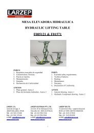
manual de instrucciones y mantenimiento instruction & maintenance ...
manual de instrucciones y mantenimiento instruction & maintenance ...
manual de instrucciones y mantenimiento instruction & maintenance ...

You also want an ePaper? Increase the reach of your titles
YUMPU automatically turns print PDFs into web optimized ePapers that Google loves.
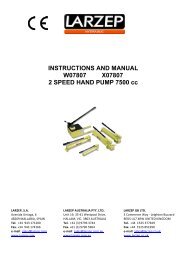
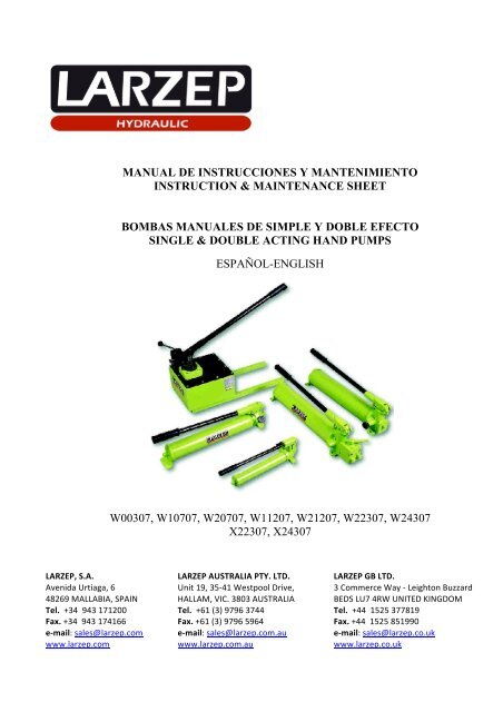
MANUAL DE INSTRUCCIONES Y MANTENIMIENTOINSTRUCTION & MAINTENANCE SHEETBOMBAS MANUALES DE SIMPLE Y DOBLE EFECTOSINGLE & DOUBLE ACTING HAND PUMPSESPAÑOL-ENGLISHW00307, W10707, W20707, W11207, W21207, W22307, W24307X22307, X24307LARZEP, S.A. LARZEP AUSTRALIA PTY. LTD. LARZEP GB LTD. Avenida Urtiaga, 6 Unit 19, 35-‐41 Westpool Drive, 3 Commerce Way -‐ Leighton Buzzard 48269 MALLABIA, SPAIN HALLAM, VIC. 3803 AUSTRALIA BEDS LU7 4RW UNITED KINGDOM Tel. +34 943 171200 Tel. +61 (3) 9796 3744 Tel. +44 1525 377819 Fax. +34 943 174166 Fax. +61 (3) 9796 5964 Fax. +44 1525 851990 e-‐mail: sales@larzep.com e-‐mail: sales@larzep.com.au e-‐mail: sales@larzep.co.uk www.larzep.com www.larzep.com.au www.larzep.co.uk
REQUISITOS ESENCIALES DE SEGURIDADLa correcta unión <strong>de</strong> una bomba con un cilindro a través <strong>de</strong> una manguera hidráulica, constituye una máquina concebida para levantar, tirar, doblar,retener etc...que por su gran capacidad <strong>de</strong> empuje requiere una utilización segura que anule la posibilidad <strong>de</strong> acci<strong>de</strong>ntes.Lea <strong>de</strong>tenidamente el <strong>manual</strong> <strong>de</strong> <strong>instrucciones</strong> y ejercite con el equipo antes <strong>de</strong> la aplicación.Utilice material <strong>de</strong> protección, tales como gafas, botas y guantes <strong>de</strong> seguridad.Gafas Botas GuantesElija un equipo que no sobrepase el 80% <strong>de</strong> su capacidad nominal durante su utilización y <strong>de</strong>ntro <strong>de</strong> la amplia gama el más a<strong>de</strong>cuadopara la aplicación.Buscar zonas estables para los puntos <strong>de</strong> aplicación <strong>de</strong> la carga y zonas seguras para los operadores, separándolos mediante el uso <strong>de</strong> manguerassuficientemente largas.Bloquear las cargas mecánicamente una vez realizado el movimiento evitando operar <strong>de</strong>bajo <strong>de</strong> estas.Utilice toda la superficie <strong>de</strong> apoyo útil <strong>de</strong>l cilindro tanto en la cabeza como en la base. Prever el uso <strong>de</strong> cabezas basculantes si existe la posibilidad <strong>de</strong> aplicarcargas laterales.No exponer los equipos a fuentes intensas <strong>de</strong> calor (soldadura).Realizar las operaciones <strong>de</strong> <strong>mantenimiento</strong> con los equipos libres <strong>de</strong> carga y en lugares limpios e iluminados.Prever en la instalación elementos <strong>de</strong> control (manómetros) que nos informen <strong>de</strong> la presión <strong>de</strong> la instalación, con el fin <strong>de</strong> no superar en ningún caso lacapacidad nominal <strong>de</strong>l equipo. Si los criterios <strong>de</strong> seguridad así lo exigen prever la utilización <strong>de</strong> válvula y accesorios <strong>de</strong> seguridad.Los mandos <strong>de</strong> la bomba <strong>de</strong>ben <strong>de</strong> actuarse <strong>manual</strong>mente, así como las conexiones entre elementos que dispongan <strong>de</strong> enchufes rápidos.Una vez utilizado el equipo, compruebe que no ha sufrido daños, límpielo y protéjalo para su almacenamiento.Limpie los enchufes rápidos antes <strong>de</strong> conectarlos y asegúrese que dicha conexión es perfecta (primeramente introducir a tope y seguidamente roscar amano). Una mala conexión pue<strong>de</strong> provocar el mal funcionamiento <strong>de</strong>l equipo e incluso pue<strong>de</strong> crear situaciones <strong>de</strong> peligro.Instalar el equipo <strong>de</strong> manera que las mangueras no sufran curvaturas agudas o forzadas o la acción <strong>de</strong> cargas que puedan provocar su rotura.No modificar los equipos (piezas soldadas, alargar palancas <strong>de</strong> accionamiento), sin consultar al fabricanteNo utilizar las mangueras para transportar los equipos. Utilizar las asas <strong>de</strong> los cilindros si las hubiera y la palanca <strong>de</strong> la bomba en posición <strong>de</strong> transporte.Al rellenar la bomba con aceite, utilizar aceite hidráulico Larzep o <strong>de</strong> semejantes características. Rellenar solamente hasta el nivel señalado y tener encuenta que el émbolo <strong>de</strong>l cilindro <strong>de</strong>be <strong>de</strong> estar recogido.Antes <strong>de</strong> efectuar cualquier tipo <strong>de</strong> aplicación asegurarse <strong>de</strong> la buena instalación, <strong>de</strong> la seguridad <strong>de</strong>l puesto <strong>de</strong>l operador y imposibilidad <strong>de</strong> que personaalguna pueda acce<strong>de</strong>r a la zona expuesta.En cualquier caso el operador <strong>de</strong>be <strong>de</strong> estar perfectamente instruido en el manejo <strong>de</strong>l equipo y actuar con los criterios lógicos <strong>de</strong> seguridad, que elmovimiento <strong>de</strong> gran<strong>de</strong>s cargas conlleva.GARANTÍALARZEP, S.A. garantiza este producto sobre todos los <strong>de</strong>fectos <strong>de</strong> diseño y fabricación durante dos años <strong>de</strong>s<strong>de</strong> la fecha <strong>de</strong> compra. Esta garantía no incluyeel uso in<strong>de</strong>bido, el <strong>de</strong>sgaste habitual tanto <strong>de</strong> piezas metálicas y no metálicas, el abuso, los daños por el uso <strong>de</strong>l equipo por encima <strong>de</strong> su capacidad, ycualquier <strong>de</strong>sgaste o uso <strong>de</strong>rivado <strong>de</strong>l empleo <strong>de</strong> fluidos hidráulicos, materiales y componentes no recomendados por LARZEP, S.A.Si el equipo ha sido vendido por un distribuidor no autorizado, o por partes incompletas, esta garantía queda anulada, sin ningún tipo <strong>de</strong> responsabilidad porparte <strong>de</strong> LARZEP, S.A.En el caso <strong>de</strong> reclamación, para el correcto uso <strong>de</strong> esta garantía, <strong>de</strong>vuelva el equipo a LARZEP, S.A. o al distribuidor autorizado que le vendió el equipo,LARZEP, S.A. reparará o reemplazará el equipo <strong>de</strong>fectuoso según se juzgue oportuno.LARZEP, S.A., no será responsable <strong>de</strong> ninguna perdida o daño que pueda ocurrir como resultado <strong>de</strong> un equipo <strong>de</strong>fectuoso.3
INSTRUCCIONES CILINDRO-BOMBA MANUALDesembale y verifique visualmente todo el equipo, asegurándose que no haya fugas <strong>de</strong> aceite, enchufes flojos o <strong>de</strong>teriorados, roscas dañadas, etc... Nuncautilice equipos dañados o presumiblemente en mal estado.Monte la instalación según las indicaciones <strong>de</strong>l dibujo comprobando que dispone <strong>de</strong> todo el material requerido.Compruebe la perfecta instalación y el buen funcionamiento <strong>de</strong>l equipo sin carga, según el siguiente procedimiento.INSTALACION SIMPLE EFECTO1. Desbloquear la palanca <strong>de</strong> accionamiento <strong>de</strong> bomba, sacando el gancho <strong>de</strong>l alojamiento <strong>de</strong>l portapalanca.2. Bombear varias veces con el tornillo <strong>de</strong> accionamiento abierto (aflojar un par <strong>de</strong> vueltas <strong>de</strong>l tope) para llenar el circuito interno <strong>de</strong> la bomba <strong>de</strong>aceite.3. Cerrar el tornillo <strong>de</strong> accionamiento, girando a <strong>de</strong>rechas con la mano. No es necesario apretar con fuerza.4. Bombear con la palanca <strong>de</strong> accionamiento. Primeramente se <strong>de</strong>be <strong>de</strong> llenar la manguera <strong>de</strong> aceite. El número <strong>de</strong> emboladas <strong>de</strong>pen<strong>de</strong>rá <strong>de</strong> lalongitud <strong>de</strong> la manguera y <strong>de</strong>l caudal que suministre el pistón <strong>de</strong> la bomba. En caso <strong>de</strong> bomba <strong>de</strong> una velocidad el caudal se mantendrá en todo elmovimiento, ya sea avance sin carga o en presión. En bombas <strong>de</strong> dos velocida<strong>de</strong>s, en el movimiento <strong>de</strong> avance sin carga actuará el pistón gran<strong>de</strong>y en el momento <strong>de</strong> contactar la carga actuará automáticamente una válvula interna <strong>de</strong> alivio <strong>de</strong>l pistón gran<strong>de</strong> y solamente dispondremos <strong>de</strong>laceite suministrado por el pistón pequeño, hasta los 700 Kg/cm que es la presión máxima <strong>de</strong>l equipo.5. Una vez la manguera está llena <strong>de</strong> aceite, el émbolo <strong>de</strong>l cilindro comenzará a avanzar.6. Si el cilindro dispone <strong>de</strong> fin <strong>de</strong> carrera mecánico con capacidad <strong>de</strong> aguantar la presión máxima <strong>de</strong> la instalación continúe bombeando hastaalcanzar el final <strong>de</strong> carrera.7. Si dispone <strong>de</strong> elementos <strong>de</strong> control (manómetro) notará que la presión aumenta, así mismo el esfuerzo en la palanca.8. Continúe bombeando hasta alcanzar la presión máxima (700 Kg/cm). De esta forma comprobará el buen funcionamiento <strong>de</strong> la válvula interna<strong>de</strong> seguridad y la ausencia <strong>de</strong> fugas <strong>de</strong> aceite en la instalación.9. Mantenga la presión en la instalación durante un tiempo, sin bombear para comprobar que funcionan perfectamente la válvula <strong>de</strong> retención <strong>de</strong> labomba.10. Abra suavemente el tornillo <strong>de</strong> accionamiento <strong>de</strong> la bomba (giro a izquierda) con el fin <strong>de</strong> proteger la11. caída <strong>de</strong> la aguja <strong>de</strong>l manómetro. No forzar el tornillo <strong>de</strong> accionamiento al soltar, no por más aflojar, el cilindro recoge más rápidamente. Un par<strong>de</strong> vueltas es suficiente.12. Si el cilindro dispone <strong>de</strong> muelle <strong>de</strong> retorno (SM, SMP, SMX, SH, TE, T, SAM, SAH, CY, KC) el émbolo se recogerá automáticamente. Lavelocidad <strong>de</strong> recogida pue<strong>de</strong> ser lenta en algunas aplicaciones. En este caso recomendamos la utilización <strong>de</strong> cilindros <strong>de</strong> doble efecto. En caso <strong>de</strong>cilindros <strong>de</strong> retorno por carga (SP, SX, SL, SSR, STR, STX) para recogerlos será necesario empujar el émbolo con más o menos fuerza<strong>de</strong>pendiendo <strong>de</strong>l tamaño y posición <strong>de</strong>l cilindro.13. En cilindros que no disponga <strong>de</strong> fin <strong>de</strong> carrera mecánico (SSR, STR, STX) no se pue<strong>de</strong> realizar este tipo <strong>de</strong> prueba. En caso <strong>de</strong> no disponer <strong>de</strong> unbanco <strong>de</strong> pruebas, será sobre la propia carga en la aplicación cuando comprobaremos la instalación, por lo que en este caso esta, <strong>de</strong>be <strong>de</strong>realizarse con la máxima atención, por personal con experiencia y las medidas <strong>de</strong> seguridad <strong>de</strong>ben <strong>de</strong> ser ampliadas.14. Repetir el proceso las veces que sea necesario para habituarse al manejo <strong>de</strong>l equipo.15. En caso <strong>de</strong> utilizar válvulas <strong>de</strong> cierre o antirretorno, o se trabaje con varios cilindros a través <strong>de</strong> distribuidores <strong>de</strong> caudal, tener en cuenta el efectoque tales accesorios pue<strong>de</strong>n tener en el funcionamiento <strong>de</strong>l equipo y marcar un proceso <strong>de</strong> actuación para no originar efectos no <strong>de</strong>seados.INSTALACION DOBLE EFECTO1. La conexión <strong>de</strong> los enchufes rápidos tiene una importancia mayor si cabe, ya que una mala conexión no solo hace que el equipo no funcione, sino que a<strong>de</strong>más pue<strong>de</strong> originar sobrepresiones que pue<strong>de</strong>n provocar la rotura <strong>de</strong>l cilindro. Tener en cuenta que manguera se conecta a la cámara<strong>de</strong> empuje y cual a la cámara <strong>de</strong> retorno.2. Todos los cilindros Larzep <strong>de</strong> doble efecto disponen <strong>de</strong> fin <strong>de</strong> carrera mecánico que soporte la presión nominal <strong>de</strong>l equipo y por tanto se podrárealizar la prueba previa <strong>de</strong>scrita en los puntos anteriores. En caso <strong>de</strong> trabajar con otro tipo <strong>de</strong> cilindro y si no se tiene seguridad absoluta no serealizará esta prueba.3. Desbloquear la palanca <strong>de</strong> accionamiento <strong>de</strong> bomba, sacando el gancho <strong>de</strong>l alojamiento <strong>de</strong>l portapalanca.4. Colocar el mando <strong>de</strong> la válvula distribuidora en posición central y bombear varias veces para llenar <strong>de</strong> aceite los conductos internos.5. Girar la palanca a un lado y bombear. El aceite fluye a través <strong>de</strong> la manguera conectada al lado <strong>de</strong>l giro <strong>de</strong> la palanca <strong>de</strong> la válvula. Si dichamanguera esta conectada a la cámara <strong>de</strong> empuje <strong>de</strong>l cilindro, el émbolo avanzará. El aceite <strong>de</strong> la cámara <strong>de</strong> retorno fluye libremente a través <strong>de</strong> laotra manguera al <strong>de</strong>pósito <strong>de</strong> la bomba. Mientras el cilindro no alcance la carga el caudal es suministrado por el pistón gran<strong>de</strong> y el pistónpequeño.6. Continuar bombeando hasta alcanzar el fin <strong>de</strong> carrera. En este momento la válvula interna <strong>de</strong> alivio <strong>de</strong>l pistón gran<strong>de</strong> actuará y solo obtendremosel aceite suministrado por el pistón pequeño. Someter a presión la instalación para comprobar que no existen fugas.7. Dejar <strong>de</strong> bombear y comprobar (preferentemente mediante un manómetro) que la instalación mantiene la presión.8. Girar la palanca <strong>de</strong> la válvula al lado contrario y bombear. El aceite fluye a la cámara <strong>de</strong> recogida, retrocediendo el émbolo. El aceite <strong>de</strong> lacámara <strong>de</strong> empuje retorna libremente al tanque.9. Repetir el proceso las veces que sea necesario para habituarse al manejo <strong>de</strong>l equipo.10. En caso <strong>de</strong> utilizar válvulas <strong>de</strong> cierre o antirretorno, o se trabaje con varios cilindros a través <strong>de</strong> distribuidores <strong>de</strong> caudal, tener en cuenta el efectoque tales accesorios pue<strong>de</strong>n tener en el funcionamiento <strong>de</strong>l equipo y marcar un proceso <strong>de</strong> actuación para no originar efectos no <strong>de</strong>seados.4
ESSENTIAL SAFETY INSTRUCTIONSThe correct union of a pump to a cylin<strong>de</strong>r via a hydraulic hose constitutes a machine <strong>de</strong>signed for lifting, pulling, folding andretaining operations, etc., that, due to its high thrust capacity requires safe use in or<strong>de</strong>r to eliminate the risk of acci<strong>de</strong>nts.Read the <strong>instruction</strong>s <strong>manual</strong> carefully and practise using the equipment before application.Use protective equipment such as safety goggles, boots and gloves.Goggles Boots GlovesChoose the most suitable mo<strong>de</strong>l for the application from the wi<strong>de</strong> range available, and make sure that it will not exceed 80% of itsnominal capacity during normal operation.Define stable zones for applying the load and safety zones for operators, separating them through the use of hoses of sufficient length.Block loads mechanically once the movement has been completed and avoids operating un<strong>de</strong>rneath them.Use the entire cylin<strong>de</strong>r’s useful support surface, both on the head and the base. Be prepared to use tilting heads if applying lateral loads.Do not exposure the equipment to intense heat sources (welding).Remove loads before carrying out <strong>maintenance</strong> operations and always work in clean, well-lit areas.Inclu<strong>de</strong> control elements (pressure gauges) in the installation in or<strong>de</strong>r to enable the operator to monitor the pressure in the system and ensure that theequipment’s nominal capacity is never excee<strong>de</strong>d. Be prepared to use safety valves and accessories if the safety criteria so <strong>de</strong>mand.The pump controls should be activated <strong>manual</strong>ly, as should the connections between elements equipped with quick plugs.Once you have finished using the <strong>de</strong>vice, check that it has not been damaged, clean it and protect it ready for storage.Clean the quick plugs before connecting and make sure the connections are perfect (first insert as far as the plug will go and then screw in by hand). A badconnection may result in improper functioning and may even generate a safety hazard.Install the <strong>de</strong>vice in such a way as to ensure that the hoses are not subjected to sharp or forced bends or thrust actions that may cause them to break.Do not modify the <strong>de</strong>vice (wel<strong>de</strong>d parts, lengthening drive levers, etc.) without consulting the manufacturer.Do not use the hoses for transporting the <strong>de</strong>vice. Use the handles on the cylin<strong>de</strong>rs (when appropriate) and set the pump lever to the transportation position.When filling the pump with oil, always use Larzep hydraulic oil or another oil of similar characteristics. Fill only to the indicated level and remember thatthe cylin<strong>de</strong>r piston should be back.Before initiating operation, check that the installation is correct, the operator position is safe and the working zone is out of bounds to all personnel.In all cases, the operator should have received a<strong>de</strong>quate training regarding the handling of the <strong>de</strong>vice and logical safety criteria associated with themovement of heavy loads.WARRANTYLARZEP, S.A. guarantees its products against all <strong>de</strong>sign and manufacturing <strong>de</strong>fects for the durations of two years from the date of purchase. This guaranteedoes not inclu<strong>de</strong> the ordinary wear of both metal and non-metal parts, abuse, using the equipment beyond its rated capacity and any wear or damage incurredas a result of using a hydraulic fluid which is not recommen<strong>de</strong>d by LARZEP, S.A.Please note that if the equipment is disassembled or serviced by anyone other than an authorized service <strong>de</strong>aler or by LARZEP, S.A., this guarantee isren<strong>de</strong>red null and void.In the event of a warranty claim, return the equipment, to LARZEP, S.A. or the authorized <strong>de</strong>aler which sold you the hydraulic equipment, LARZEP, S.A.will repair or replace the faulty equipment, whichever is <strong>de</strong>emed most appropriate. LARZEP, S.A. shall not be held liable for any consequential damages orlosses, which may occur as a result of faulty equipment5
CYLINDER-HAND PUMP INSTRUCTIONSUnpack and visually check all the components, making sure that there are no oil leaks, loose or damaged plugs, damaged threads, etc. Never use componentsthat are damaged or appear to be in poor condition.Assemble the <strong>de</strong>vice in accordance with the <strong>instruction</strong>s given in the diagram, first checking that you have all the necessary material.Check the correct installation and perfect functioning of the <strong>de</strong>vice with a load, in accordance with the procedure outlined below:SINGLE ACTION INSTALLATION1. Release the pump drive lever by removing the hook from the lever-hol<strong>de</strong>r housing.2. Pump <strong>manual</strong>ly with the drive screw open (rotate a few times to loosen) in or<strong>de</strong>r to fill the pump’s internal circuit with oil.3. Close the drive screw by turning clockwise <strong>manual</strong>ly. You do not need to close too tightly.4. Now pump using the drive lever. First, fill the hose with oil. The number of thrusts required will <strong>de</strong>pend on the length of the hose and the flowsupplied by the pump piston. With single-speed pumps, the flow will remain the same at all times, regardless of the load or pressure. With twospeedpumps, the large piston will be activated during the load-free feed movement, and when the <strong>de</strong>vice comes into contact with the load, aninternal large piston relief value will be automatically triggered and only the oil supplied by the small piston will be available up to 700 kg/cm”,which is the maximum pressure for the <strong>de</strong>vice.5. Once the hose is full of oil, the cylin<strong>de</strong>r piston will start to advance.6. If the cylin<strong>de</strong>r has a mechanical limit switch capable of withstanding the maximum <strong>de</strong>vice pressure, continue pumping until the limit switch isreached.7. If any control elements (pressure gauges) are available, you will be able to see how the pressure increases along with the effort required to movethe lever.8. Keep pumping until you obtain the maximum pressure (700 kg/cm”). In this way you will be able to check the correct functioning of the internalsafety valve and the absence of oil leaks in the installation.9. Maintain pressure in the installation for a short period of time (1 minute) without pumping, in or<strong>de</strong>r to check the correct functioning of thepump’s check valve.10. Gently open the pump’s drive screw (by turning anticlockwise) in or<strong>de</strong>r to protect the fall of the pressure gauge needle. Do not force the drivescrew open. The cylin<strong>de</strong>r will not move back more quickly because the screw is looser. A couple of turns will be sufficient.11. If the cylin<strong>de</strong>r has a return spring (SM, SMP, SMX, SH, TE, T, SAM, SAH, CY, KC) the piston will move back automatically. The return speedmay be slow in some applications. In this case, we recommend the use of double effect cylin<strong>de</strong>rs. In the case of load return cylin<strong>de</strong>rs (SP, SX,SL, SSR, STR, STX), you will need to push the piston back using more or less force, <strong>de</strong>pending on the size and position of the cylin<strong>de</strong>r.12. In cylin<strong>de</strong>rs without a mechanical limit switch (SSR, STR, STX) this type of test cannot be carried out. If you do not have a test bench, you willhave to test the installation using the actual load in the application. This operation should be carried out with extreme care by experiencedpersonnel and maximum safety measures should be applied.13. Repeat the processes as many times as necessary until you are comfortable handling the <strong>de</strong>vice.14. If using close or check valves, or working with various cylin<strong>de</strong>rs via flow distributors, remember to take into consi<strong>de</strong>ration the effect theseaccessories may have on the functioning of the <strong>de</strong>vice, and establish an operating procedure in or<strong>de</strong>r to avoid unwanted effects.DOUBLE ACTION INSTALLATION1. The connection of the quick plugs is, if possible, even more important here, since a bad connection will not only prevent the <strong>de</strong>vice fromfunctioning, it may also generate excessive pressure build-up that may cause the cylin<strong>de</strong>r to break. Take note of which hose connects to the thrustchamber and which to the return chamber.2. All double action Larzep cylin<strong>de</strong>rs are equipped with a mechanical limit switch capable of withstanding the nominal pressure. You can thereforecarry out the test <strong>de</strong>scribed in the previous section. If you are working with another type of cylin<strong>de</strong>r and are not 100% sure, do not carry out thistest.3. Release the pump drive lever by removing the hook from the lever-hol<strong>de</strong>r housing.4. Turn the control of the distributing valve to the central position and pump and few times to fill the internal channels with oil.5. Turn the lever to one si<strong>de</strong> and pump. Oil will flow through the hose connected to the si<strong>de</strong> to which the valve lever is rotated. If this hose isconnected to the cylin<strong>de</strong>r’s thrust chamber, the piston will move forward. The oil in the return chamber will flow freely through the other hose tothe pump tank. Until the moment the cylin<strong>de</strong>r connects with the load, flow is supplied by both the large and small pistons.6. Continue pumping until you reach the limit switch. At this moment an internal large piston relief value will be triggered, and only the oil suppliedby the small piston will be available. Subject the installation to pressure to check for leaks.7. Stop pumping and check (preferably using a pressure gauge) that the installation maintains the pressure level.8. Turn the valve lever to the other si<strong>de</strong> and pump. Oil will flow to the return chamber and the piston will move back. The oil in the thrust chamberwill flow freely back to the tank.9. Repeat the processes as many times as necessary until you are comfortable handling the <strong>de</strong>vice.10. If using close or check valves, or working with various cylin<strong>de</strong>rs via flow distributors, remember to take into consi<strong>de</strong>ration the effect theseaccessories may have on the functioning of the <strong>de</strong>vice, and establish an operating procedure in or<strong>de</strong>r to avoid unwanted effects.6
MANTENIMIENTO Comprobación <strong>de</strong>l nivel <strong>de</strong> aceite.Con la bomba en posición vertical (base (1) abajo), soltar el tapón (16). En el mo<strong>de</strong>lo W00307 el nivel se consigue por <strong>de</strong>sbordamiento <strong>de</strong>l aceite porel agujero. En los otros mo<strong>de</strong>los comprobar el nivel en la varilla <strong>de</strong>l tapón.Esta verificación se realizara con el cilindro recogido. Un exceso <strong>de</strong> aceite en el <strong>de</strong>pósito origina presiones internas que provocan un malfuncionamiento <strong>de</strong> la bomba.Filtrar el aceite antes <strong>de</strong> introducirlo en el <strong>de</strong>pósito.• Una vez utilizado el equipo, limpiarlo y engrasar las zonas expuestas a <strong>de</strong>sgaste u oxidación. La articulación en la palanca <strong>de</strong> accionamiento <strong>de</strong> labomba y las roscas <strong>de</strong>l cilindro.AVERIAS Y REPARACIONES• EL CILINDRO NO AVANZA AL BOMBEAR.- Falta <strong>de</strong> aceite en el <strong>de</strong>pósito ____ Revisar el nivel.- Incorrecta conexión <strong>de</strong> enchufes____ Revisar las conexiones.- Cierre <strong>de</strong>fectuoso <strong>de</strong> la bola <strong>de</strong> admisión (19) ____ Corregir el asiento y cambiar la bola.- Cierre <strong>de</strong>fectuoso <strong>de</strong> la bola <strong>de</strong> cierre (22) ____ Corregir el asiento y cambiar la bola.• EL CILINDRO NO ALCANZA O NO RETIENE LA PRESIÓN.- Válvula limitadora (12) <strong>de</strong>starada ____ Retarar la válvula.- Cierre <strong>de</strong>fectuoso <strong>de</strong> la bola <strong>de</strong> retención (20) ____ Corregir el asiento y cambiar la bola.- Cierre <strong>de</strong>fectuoso <strong>de</strong> la bola <strong>de</strong> cierre (22) ____ Corregir el asiento y cambiar la bola.- Retén <strong>de</strong> presión dañado (26) ____ Cambiar el retén.- Retén <strong>de</strong>l cilindro dañado ____ Cambiar el retén.• EL CILINDRO NO RETORNA.- Demasiado aceite en el <strong>de</strong>pósito ____ Revisar el nivel.MAINTENANCE Oil level check.With the pump in vertical position (base (1) downwards), unscrew or pry off the plug (16). On the W00307 mo<strong>de</strong>l the level is obtained by overflowthrough the filling hole. On the other mo<strong>de</strong>ls check the level on the dip stick.This check must be carried out with the cylin<strong>de</strong>r fully retracted. Excessive amount of oil in the tank will lead to internal pressures which will hamperthe function of the pump.Filter the oil before filling up the pump.• Once the equipment is being used the areas exposed to wear and oxidation must be cleaned and greased.BREAK DOWNS AND REPARATIONS• THE CYLINDER DOESN´T AVANCE- Lack of oil in the tank ____ Check the oil.- Couplers not fully inserted ____ Check couplers.- Admission ball valve failure (19) ____ Clean the seat and replace the ball.- Closing ball valve failure (22) ____ Clean the seat and replace the ball.• THE CYLINDER DOESN´T REACH WORKING PRESSURE.- Relief valve no calibrated (12) ____ Calibrate the valve.- Retention ball valve failure (20) ____ Clean the seat and replace the ball.- Closing ball valve failure (22) ____ Clean the seat and replace the ball.- Pressure seal damaged (26) ____ Replace the seal.- Cylin<strong>de</strong>r pressure seal damaged (see cylin<strong>de</strong>r) ____ Replace the seal.• THE CYLINDER DOESN´T RETRACT- Too much oil in the tank ____ Check the level.7
DESPIECE BOMBAS MANUALES SIMPLE EFECTOHAND PUMP SINGLE-ACTING PARTS LISTReferencias / Mo<strong>de</strong>ls: W00307, W10707, W20707, W11207, W21207, W22307, W24307Nº Denominación/<strong>de</strong>scription W00307 W10707 W20707 W11207 W21207 W22307 W24307 **1 Base/ base 50K0050 50K0032 50K0034 50K0032 50K0034 50K0006 50K00072 Camisa/ body 15D0002 15D0023 15D00233 Pistón/ piston 54A0031 54C0004 54B0003 54C0004 54B0003 54B0001 54B00024 Portapalancas/ handle socket 24B0005 24B0037 24B0037 24B0037 24B0037 24B0037 24B00375 Palanca/ handle 24A0005 24A0070 24A0070 24A0070 24A0070 24A0070 24A00706 Empuñadura/ handle grip 24C0004 24C0006 24C0006 24C0006 24C0006 24C0006 24C00067 Tornillo accionamiento/ release screw 15H0017 15H0017 15H0017 15H0017 15H0017 15H0017 15H00178 Tirante inyector/ Inyector 24F00069 Depósito/ tank 51B0017 51B0042 51B0042 51B0065 51B0065 51B0022 51B006810 Tapa <strong>de</strong>pósito/ end cap 15L0095 32A0013 32A0013 32A0014 32A0014 32A0006 15L004311 Eje <strong>de</strong>pósito/`tie rod 15I0273 15I0003 15I0003 15I0160 15I0160 15I0005 15I000612 Válvula limitadora/ relief valve (700) 17C0002 17C0006 17C0028 17C0006 17C0028 17C0003 17C000313 Válvula limitadora/ relief valve (20) 17C0028 17C0028 17C0004 17C000414 Eje portapalancas/ hand socket pin 15A0008 15I0348 15I0348 15I0348 15I0348 15I0348 15I034815 Eje pistón/ piston pin 15A0012 15I0347 15I0347 15I0347 15I0347 15I0347 15I034716 Tapón-Tapón nivel/ plug-plug label 12C0026 15L0117 15L0117 15L0042 15L0117 15L0044 15L004417 Tuerca cierre <strong>de</strong>pósito/ acorn nut 14B0004 14B0004 14B0004 14B0004 14B0004 14B0004 14B000518 Filtro/ filter 13F0001 13F0001 13F0001 13F0001 13F0001 13F0003 13F0003 **19 Bola <strong>de</strong> admisión/ admision ball 31A0001 31A0002 31A0001* 31A0001 31A0001* 31A0001* 31A0001* **20 Bola <strong>de</strong> retención/ ball 31A0001 31A0001 31A0005* 31A0002 31A00o5* 31A0005* 31A0005* **21 Eje tirante inyector/ pin 15A001422 Bola cierre/ ball 31A0001 31A0001 31A0001 31A0001 31A0001 31A0001 31A000123 Tórica tornillo accionamiento/ O-ring 12A0047 12A0047 12A0047 12A0047 12A0047 12A0047 12A0047 **24 Junta base-<strong>de</strong>pósito/ joint 57F0015 57F0016 57F0016 57F0016 57F0016 57F0019 57F0018 **25 Junta <strong>de</strong>pósito-tapa/ joint 57F0015 57F0016 57F0016 57F0017 57F0017 57F0019 57F0018 **26 Taza pistón/ Seal U-cup 12J0001 12J0004 12J0004 12J0004 12J0004 12J0004 12J0004 **27 Tórica <strong>de</strong> apoyo/ O-ring 12A0272 12A0051 12A0051 **28 Aran<strong>de</strong>la cierre camisa/ washer 27A0004 57B0011 57B003829 Tórica cierre tuerca <strong>de</strong>pósito/ O-ring 12A0048 12A0048 12A0048 12A0048 12A0048 12A0048 12A0049 **30 Pata trasera/ foot 24L0037 24L0015 24L0015 24L0003 24L0003 24L0004 24L000531 Tornillo cierre/ screws 14A0001 15O0004* 15O0004* 15O0004* 15O0004*32 Tórica tornillo cierre/ O-ring 12A0022 12A0056* 12A0056* 12A0056* 12A0056*33 Pasador tope portapalancas/ elastic pin 14E0002 14E0002 14E0002 14E000234 Horquilla portapalancas/ transport pin 15I0159 15I0159 15I0159 15I0159 15I0165 15I016535 Muelle horquilla/ spring 13D0003 13D0003 13D0003 13D0003 13D0004 13D000436 Aran<strong>de</strong>la horquilla/ washer 14C0004 14C0004 14C0004 14C0004 14C0004 14C000437 Aran<strong>de</strong>la presión / elastic washer 14D0042 14D0042 14D0042 14D0042 14D0042 14D004238 Tope tornillo accionamiento/ screw 14A0400 15L0400 15L0400 15L040039 Muelle bola antiretorno 1º/ spring 13D0136 13C0008 13D0136 13C0008 13D0003 13D004740 Muelle bola antiretorno 2º/ spring 13C0008 13C0008 13D0004 13D000441 Muelle bola admisión/ spring 13C0018 13C001842 Tórica cierre pistón baja/ O-ring 12A0108 12A0108 12A0055* 12A0055* **43 Segmento tórica pistón baja/ segment 57A0222 57A0222 **44 Guía pistón baja/ gui<strong>de</strong> 58F0210 58F0210 **45 Cierre tapón nivel/aran<strong>de</strong>la/ plug seal 12A0051 12A0051 12A0056 12A0056 14C0013 14C0013 **46 Clip eje portapalancas/ clip 14D0001* 14D0001* 14D0001* 14D0001* 14D0001* 14D0001*47 Tapón/ plug AZ1182 AZ1182 AZ1182 AZ1182 AZ1182 AZ1182 AZ118248 Tornillo cierre camara alta/ screw 15O0002 15O000249 Tórica tornillo cierre/ O-ring 12A0020 12A0020 **50 Estuche cartón/ box 21D0017 21D0019 21D0019 21D0019 21D0019 21D0019 21D002051 Etiqueta/ label 30A0017 30A0023 30A0023 30A0023 30A0023 30A0023 30A0023** Juego <strong>de</strong> recambios/Spare parts* Dos piezas/Two pieces9
DESPIECE BOMBAS MANUALES DOBLE EFECTOHAND PUMP DOUBLE-ACTING PARTS LISTReferencias / Mo<strong>de</strong>ls: X22307, X24307Nº Denominación/<strong>de</strong>scription X22307 X24307 JR/SP Nº Denominación/<strong>de</strong>scription X22307 X24307 JR/SP1 Base/ base 50K0061 50K0063 41 Muelle bola admisión/ spring 13C0018 13C00182 Camisa/ body 42 Tórica cierre pistón baja/ O-ring 12A0055(2) 12A0055(2) *3 Pistón/ piston 54B0001 54B0002 43 Tornillos amarre/ screw 14A0201(4) 14A0201(4)4 Portapalancas/ handle socket 24B0037 24B0037 44 Guía pistón baja/ gui<strong>de</strong> 58F0210 58F0210 *5 Palanca/ handle 24A0070 24A0070 45 Cierre tapón nivel/aran<strong>de</strong>la/ plug seal 14C0013 14C0013 *6 Empuñadura/ handle grip 24C0006 24C0006 46 Clip eje portapalancas/ clip 14D0001(2) 14D0001(2)7 Tornillo accionamiento/ release screw 47 Tapón/ plug AZ1182 AZ11828 Tirante inyector/ Inyector 48 Tornillo cierre camara alta/ screw 15O0002 15O00039 Depósito/ tank 51B0022 51B0068 49 Tórica tornillo cierre/ O-ring 12A0020 12A0020 *10 Tapa <strong>de</strong>pósito/ end cap 32A0006 15L0043 50 Estuche cartón/ box 21D0021 21D002211 Eje <strong>de</strong>pósito/`tie rod 15I0005 15I0006 51 Etiqueta/ label 30A0023 30A002312 Válvula limitadora/ relief valve (700) 17C0006 17C0006 52 Conjunto válvula/ valve AZ8400X AZ8400X13 Válvula limitadora/ relief valve (20) 17C0006 17C0006 53 Cuerpo válvula/ body 52Y0064 52Y006414 Eje portapalancas/ hand socket pin 15I0347 15I0347 54 Distribuidor/ manifold 17B0002 17B000215 Eje pistón/ piston pin 15I0348 15I0348 55 Tapa/ cover 15L0097 15L009716 Tapón-Tapón nivel/ plug-plug label 15L0044 15L0044 56 Eje/ saft 15I0306 15I030617 Tuerca cierre <strong>de</strong>pósito/ acorn nut 14B0004 14B0005 57 Palanca/ handle 24A0057 24A005718 Filtro/ filter 13F0003 13F0003 * 58 Tornillo valvula/ valve screw 15O0010 (2) 15O0010 (2)19 Bola <strong>de</strong> admisión/ admision ball 31A0001(2) 31A0001(2) * 59 Aran<strong>de</strong>la/ ring 57B0008 (2) 57B0008 (2) *20 Bola <strong>de</strong> retención/ ball 31A0005(2) 31A0005(2) * 60 Tornillo tapa/ cover screw 14A0002 (4) 14A0002 (4)21 Eje tirante inyector/ pin 61 Piston/ piston 54F0001 (5) 54F0001 (5)22 Bola cierre/ ball 62 Junta torica/ o-ring 12A0059 (6) 12A0059 (6) *23 Tórica tornillo accionamiento/ O-ring 63 Segmento / antiextrusion segment 57A0058 (5) 57A0058 (5) *24 Junta base-<strong>de</strong>pósito/ joint 57F0019 57F0018 * 64 Muelle/ spring 13D0009 (5) 13D0009 (5) *25 Junta <strong>de</strong>pósito-tapa/ joint 57F0019 57F0018 * 65 Pasador elastico/ elastic pin 14E0010 14E001026 Taza pistón/ Seal U-cup 12J0004 12J0004 * 66 Esfera 4/ ball 31A0002 31A0002 *27 Tórica <strong>de</strong> apoyo/ O-ring 12A0051 12A0051 * 67 Muelle/ spring 13D0008 13D000828 Aran<strong>de</strong>la cierre camisa/ washer 68 Pasador elastico/ elastic pin 14E0011 14E001129 Tórica cierre tuerca <strong>de</strong>pósito/ O-ring 12A0048 12A0049 * 69 Rodamiento/ bearing 31B0002 31B000230 Pata trasera/ foot 24L0004 24L0005 70 Junta torica/ o-ring 12A0077 12A0077 *31 Tornillo cierre/ screws 15O0004(2) 15O0004(2) 71 Esfera 6/ ball 31A0001 (2) 31A0001 (2) *32 Tórica tornillo cierre/ O-ring 12A0056(2) 12A0056(2) 72 Muelle/ spring 13D0043 (2) 13D0043 (2)33 Pasador tope portapalancas/ elastic pin 73 Junta torica/ o-ring 12A0420 12A0420 *34 Horquilla portapalancas/ transport pin 15I0165 15I0165 74 Tapón 3/8 NPT/ 3/8 NPT plug 15L0055 (2) 15L0055 (2)35 Muelle horquilla/ spring 13D0004 13D0004 75 Pasador elastico/ elastic pin 14E0039 14E003936 Aran<strong>de</strong>la horquilla/ washer 14C0004 14C0004 76 Base valve/ 50M0059 (2) 50M0059 (2)37 Aran<strong>de</strong>la presión horquilla/ elastic washer 14D0042 14D0042 77 Tornillo / screw 14A0003 (4) 14A0003 (4)38 Tope tornillo accionamiento/ screw39 Muelle bola antiretorno 1º/ spring 13D0003 13D004740 Muelle bola antiretorno 2º/ spring 13D0004 13D000411
• CILINDROS/CYLINDERS• BOMBAS MANUALES/HAND PUMPS• BOMBAS ELÉCTRICAS/ELECTRIC PUMPS• BOMBAS DE AIRE/AIR PUMPS• GATOS DE BOTELLA/BOTTLE JACKS• GATOS TELESCÓPICOS/TELESCOPIC BOTTLE JACKS• GATOS DE CARRETILLA/TROLLEY JACKS• GATOS HIDRONEUMÁTICOS/AIR HYDRAULIC JACKS• GATOS DE FOSO/HIGH LIFT JACKS• CURVADORAS/BENDERS• EXTRACTORES/PULLERS• PINZAS SEPARADORAS/SPREAD CYLINDERS• PRENSAS/PRESSES• GRÚAS/CRANES• MESAS ELEVADORAS/TABLES• EQUIPO DE MANTENIMIENTO/MAINTENANCE SETS• CORTA CABLES/CABLE CUTTERS• CORTA CADENAS/CHAIN CUTTERS• DEFORMA TUERCAS/NUT DEFORMERS• EQUIPOS DE RESCATE/RESCUE EQUIPMENT• EQUIPOS ESPECIALES A MEDIDA/SPECIAL APPLICATIONS TAYLOR MADE12