cn0324 - Larzep Australia Pty Ltd
cn0324 - Larzep Australia Pty Ltd
cn0324 - Larzep Australia Pty Ltd

You also want an ePaper? Increase the reach of your titles
YUMPU automatically turns print PDFs into web optimized ePapers that Google loves.
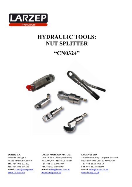
HYDRAULIC TOOLS:NUT SPLITTER“CN0324”LARZEP, S.A. LARZEP AUSTRALIA PTY. LTD. LARZEP GB LTD. Avenida Urtiaga, 6 Unit 19, 35-‐41 Westpool Drive, 3 Commerce Way -‐ Leighton Buzzard 48269 MALLABIA, SPAIN HALLAM, VIC. 3803 AUSTRALIA BEDS LU7 4RW UNITED KINGDOM Tel. +34 943 171200 Tel. +61 (3) 9796 3744 Tel. +44 1525 377819 Fax. +34 943 174166 Fax. +61 (3) 9796 5964 Fax. +44 1525 851990 e-‐mail: sales@larzep.com e-‐mail: sales@larzep.com.au e-‐mail: sales@larzep.co.uk www.larzep.com www.larzep.com.au www.larzep.co.uk
Instruction ManualNut- Splitter “CN0324”INDEX1. BEFORE USING THE EQUIPMENT --------------------------- 22. TECHNICAL FEATURES ----------------------------------------- 23. ESSENTIAL SAFETY REQUIREMENTS --------------------- 34. START-UP ------------------------------------------------------------- 35. MAINTENANCE ----------------------------------------------------- 36. WARRANTY ---------------------------------------------------------- 37. DECLARATION OF CONFORMITY -------------------------- 4ANNEX• GENERAL DRAWING1. BEFORE USING THE EQUIPMENT.Remove the tool from its packaging and check for external damage, such as:o a broken cutting blade.o a damaged levers.o a loosed/unscrewed parts.LARZEP hydraulic tools are designed in accordance with internal quality standards, in compliance with the ISO 9001 regulation.The tools are designed for the applications described in this manual. Any other use may pose a risk to the equipment and result in hazardous situations for theoperator.The manufacturer accepts no responsibility for damage resulting from the improper use of the tool.Check that the machine and accessories have not been damaged in any way during transportation to the plant. Always use the tools in well-lit areas.Never use hydraulic equipment that is damaged or suspected to be in poor condition.The operator should be fully aware of the risks inherent in the use of high-pressure hydraulic tools, and should act responsibility in accordance with that described inthis manual, ensuring both his/her own safety as well as the safety of others located in the vicinity of the working zone.Do not loose instruction manual.The working instructions should be available for consultation by the operator at all times.In addition to reading and understanding the instructions manual, the operator should be trained in the use of the machine and in the standards and regulationsgoverning operations of this kind, such as those pertaining to accident prevention and environmental protection, for example. All exposed personnel should useappropriate personal protection equipment: boots, helmet, goggles, gloves and protective clothing.Boots Helmet Goggles Gloves Clothes2. TECHNICAL FEATURES.The tools in the CN cable cutter range are designed to cut cables and bars in accordance with the specifications contained in the table below. Any other use notincluded in the said specifications may cause irreparable damage to the cutter and render it unable to carry out the task for which it was designed.When using the cable cutter, the operator should take steps to prevent the cable from fraying. We recommend that, before commencing the cutting operation, thecable be attached to either end of the cutting zone, using tape, wire or another similar means.MODELS CN0024 CN0224 CN0324 CN0233 CN0152 CN0180CAPACITY kN 137,4 kN 137,4 kN 137,4 kN 345,1 kN 436,8 kN 1133,94 kNMAXIMUM SPLITTINGCAPACITY DEPENDING ONTHE NUT QUALITY.12 / 98 / 85 / 6M24 7/8”M24 1”M24 1”-M24 7/8“M24 7/8“-M24 7/8“M24 7/8“M36 1 3/8“M36 1 3/8“M36 1 3/8“M52 2“M52 2“M52 2“M80 3“M80 3“M80 3“MINIMUM NUT DIMENSION M 12 ½” M 12 ½” M16 5/8” M25 1” M36 1 ½” M72 2 ¾”REFERENCE BLADE CRN24 CRN0224 CRN0324 CRN0233 CRN33-52 CRN0180DIMENSIONSA mmB mmC mmD mmE mmF mmG mm68 mm471 mm12,5 mm51,5 mm-108 mm48 mm65 mm207 mm12 mm30,3 mm-56 mm40 mm104,5 mm296 mm21,5 mm27 mm68,5 mm62 mm38 mm106 mm320 mm14 mm55 mm-74 mm60 mm130,5 mm368 mm17 mm55 mm120 mm136,5 mm83 mm185 mm435 mm37 mm90 mm200 mm202,5 mm120 mmWEIGHT Kg. 4,3 Kg. 3,7 Kg. 5 Kg. 15 Kg. 13 Kg. 40 Kg.2
Instruction ManualNut- Splitter “CN0324”3. ESSENTIAL SAFETY REQUIREMENTS.In the event of the improper working of the machine or one of the connected elements, immediately halt all operation, depressurise the system and resolve theproblem.Before beginning operation, make sure that the danger zone is unoccupied.Always use the tools in well-lit areas.Regardless of whether the cutting tool has a built-in or separate pump, try to establish the most convenient and stable working method for both the tool and theoperator.Allow for a general use at 80% of the tool’s nominal capacity do not exceed the tool’s nominal capacity.In the case of tools with separate pumps, we recommend the use of a pressure indicator, in order to enable the operator to monitor at all times theforce to which the system is subjectedIn the case of tools with a separate pump, the hose enables the operator to move further away from the danger zone, while in the case of tools with built-inpumps, if possible, a guard should be positioned between the work piece and the operator.Do not expose tools to intense heat sources, such as welding equipment, for example.Depressurise and disconnect the tools before carrying out any maintenance operationsIn the case of tools with separate pumps, make sure all the quick plugs are completely clean before connecting.Make sure that the hydraulic hoses are neither twisted nor unduly tensed.When working with an electric pump, make sure that the valve is set to its neutral position before connecting the tool.When working with cable cutters, fraying may occur during the cutting operation. To avoid this, clamp the cable to either end of the cutting blade with tape,wire or even a bushing.Clean the quick plugs thoroughly before connecting.In all cases, the operator should be thoroughly trained in the operation of the tool and should act in accordance with the logical safety criteria associated withthe use of high-pressure equipment.4. START UP.MODELS WITH IN-BUILT PUMP.CN00241- Hold the tool by the thick handle and with the tool in an upright position(head facing up.MODELS WITH A SEPARATE PUMP.CN0224, CN0324, CN0233, CN0152,CN01801- Connect the hose’s female quick plug to the tool’s male plug. Make surethe connection is secure.2- Pump the lever to check that the blade moves forward. 2- Read and follow the pump instructions.3- Make sure the deformation zone is free from obstruction, and then continuepumping until the blade reaches the end of its travel. At this point the lever willbecome stiffer and harder to move.4-Continue pumping until the safety valve is activated. Check for oil leaks.5- Press the unload button and check that the blade returns to its initial position.6- Repeat this operation as many times as necessary in order to become familiarwith the operation of the tool.7- Place the tool in position of work supporting the flat part on the bridle.8- Look for the position in that the blade affects one of the faces of the hexagonand pump until the blade between in contact with the nut.9- Continue pumping until deforming the nut sufficient so that the takeoff of pin.10- Unscrew completely the nut with the help of a key.5. MAINTENANCE.3- Remove the pin and open the tool head.4- When using electric or air-based pumps, the application is automated. Insuch cases, the operator should be specially trained, in order to avoid thepossibility of involuntary actions. After use, the tool should be cleaned and the area where the blade comes into contact with the heads oiled. In the event of oil leaks, disassemble the tool and change the seals. The individual blueprint provided for each tool specifies its components and codes. During this operation, check the condition of the inside of the cylinder. If scratches or snags are detected, then a more thorough repair procedure will berequired. We recommend that this be carried out by specialist personnel. In the event of improper functioning in the models with built-in pumps, we recommend that you send the tool to an authorised technical service forinspection and repair.CHANGING THE BLADE. Model CN0024: Release two Allen M5x15 (51) screws, remove the blade and replace it with a new one and attach it by tightening the screw (22) onceagain. Model CN0324: Release the pin (5), unscrew the head (3) and remove the blade using the screw (17). Models CN0224, CN0233, CN0152 y CN0180: Release the pin (14) and remove the piston with the pump until the screw (13) its above the hole. Releasethe screw (13) and remove the blade by the head, replace it, and fix it with the screw (13).Retract the piston and thread the pin (14).6. WARRANTY.LARZEP, S.A. guarantees its products against all design and manufacturing defects for the durations of two years from the date of purchase. This guarantee does notinclude the ordinary wear of both metal and non-metal parts, abuse, using the equipment beyond its rated capacity and any wear or damage incurred as a result ofusing a hydraulic fluid which is not recommended by LARZEP, S.A.Please note that if the equipment is disassembled or serviced by anyone other than an authorized service dealer or by LARZEP, S.A., this guarantee is rendered nulland void.In the event of a warranty claim, return the equipment, to LARZEP, S.A. or the authorized dealer which sold you the hydraulic equipment, LARZEP, S.A. willrepair or replace the faulty equipment, whichever is deemed most appropriate. LARZEP, S.A. shall not be held liable for any consequential damages or losses,which may occur as a result of faulty equipment.3
Instruction ManualNut- Splitter “CN0324”7. DECLARATION OF CONFORMITY.4
Instruction ManualNut- Splitter “CN0324”5