W07807-X07807 - Larzep Australia Pty Ltd
W07807-X07807 - Larzep Australia Pty Ltd
W07807-X07807 - Larzep Australia Pty Ltd

You also want an ePaper? Increase the reach of your titles
YUMPU automatically turns print PDFs into web optimized ePapers that Google loves.
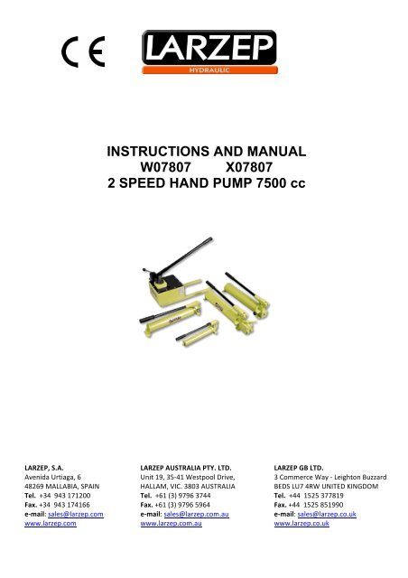
INSTRUCTIONS AND MANUAL<br />
<strong>W07807</strong> <strong>X07807</strong><br />
2 SPEED HAND PUMP 7500 cc<br />
LARZEP, S.A. LARZEP AUSTRALIA PTY. LTD. LARZEP GB LTD. <br />
Avenida Urtiaga, 6 Unit 19, 35-‐41 Westpool Drive, 3 Commerce Way -‐ Leighton Buzzard <br />
48269 MALLABIA, SPAIN HALLAM, VIC. 3803 AUSTRALIA BEDS LU7 4RW UNITED KINGDOM <br />
Tel. +34 943 171200 Tel. +61 (3) 9796 3744 Tel. +44 1525 377819 <br />
Fax. +34 943 174166 Fax. +61 (3) 9796 5964 Fax. +44 1525 851990 <br />
e-‐mail: sales@larzep.com e-‐mail: sales@larzep.com.au e-‐mail: sales@larzep.co.uk <br />
www.larzep.com www.larzep.com.au www.larzep.co.uk
Instruction Manual<br />
Hydraulic Hand Pump “<strong>W07807</strong>”, “<strong>X07807</strong>”<br />
INDEX<br />
1. BEFORE USING THE EQUIPMENT AND SECURITY -------------------------- 2<br />
2. WARRANTY --------------------------------------------------------------------------------- 2<br />
3. TECHNICAL FEATURES ---------------------------------------------------------------- 3<br />
4. START UP --------------------------------------------------------------------------------- 3-4<br />
5. MAINTENANCE ---------------------------------------------------------------------------- 4<br />
6. DECLARATION OF CONFORMITY ------------------------------------------------- 5<br />
ANNEX<br />
GENERAL DRAWING<br />
1. BEFORE USING THE EQUIPMENT AND SECURITY.<br />
The correct union of a pump to a cylinder via a hydraulic hose constitutes a machine designed for lifting, pulling, folding and<br />
retaining operations, etc., that, due to its high thrust capacity requires safe use in order to eliminate the risk of accidents.<br />
Read the instructions manual carefully and practise using the equipment before application.<br />
Use protective equipment such as safety goggles, boots and gloves.<br />
Goggles Boots Gloves<br />
Choose the most suitable model for the application from the wide range available, and make sure that it will not exceed 80% of its<br />
nominal capacity during normal operation.<br />
Define stable zones for applying the load and safety zones for operators, separating them through the use of hoses of sufficient length.<br />
Block loads mechanically once the movement has been completed and avoid operating underneath them.<br />
Use all the cylinder’s useful support surface, both on the head and the base. Be prepared to use tilting heads if applying lateral loads.<br />
Do not exposure the equipment to intense heat sources (welding).<br />
Remove loads before carrying out maintenance operations and always work in clean, well-lit areas.<br />
Include control elements (pressure gauges) in the installation in order to enable the operator to monitor the pressure in the system and ensure that the equipment’s<br />
nominal capacity is never exceeded. Be prepared to use safety valves and accessories if the safety criteria so demand.<br />
The pump controls should be activated manually, as should the connections between elements equipped with quick plugs.<br />
Once you have finished using the device, check that it has not been damaged, clean it and protect it ready for storage.<br />
Clean the quick plugs before connecting and make sure the connections are perfect (first insert as far as the plug will go and then screw in by hand). A bad<br />
connection may result in improper functioning and may even generate a safety hazard.<br />
Install the device in such a way as to ensure that the hoses are not subjected to sharp or forced bends or thrust actions that may cause them to break.<br />
Do not modify the device (welded parts, lengthening drive levers, etc.) without consulting the manufacturer.<br />
Do not use the hoses for transporting the device. Use the handles on the cylinders (when appropriate) and set the pump lever to the transportation position.<br />
When filling the pump with oil, always use LARZEP hydraulic oil or another oil of similar characteristics. Fill only to the indicated level and remember that the<br />
cylinder piston should be back.<br />
Before initiating operation, check that the installation is correct, the operator position is safe and the working zone is out of bounds to all personnel.<br />
In all cases, the operator should have received adequate training regarding the handling of the device and logical safety criteria associated with the movement of<br />
heavy loads.<br />
2. WARRANTY .<br />
LARZEP, S.A. guarantees its products against all design and manufacturing defects for the durations of two years from the date of purchase. This guarantee does not<br />
include the ordinary wear of both metal and non-metal parts, abuse, using the equipment beyond its rated capacity and any wear or damage incurred as a result of<br />
using a hydraulic fluid which is not recommended by LARZEP, S.A.<br />
Please note that if the equipment is disassembled or serviced by anyone other than an authorized service dealer or by LARZEP, S.A., this guarantee is rendered null<br />
and void.<br />
In the event of a warranty claim, return the equipment, to LARZEP, S.A. or the authorized dealer which sold you the hydraulic equipment, LARZEP, S.A. will<br />
repair or replace the faulty equipment, whichever is deemed most appropriate. LARZEP, S.A. shall not be held liable for any consequential damages or losses,<br />
which may occur as a result of faulty equipment<br />
2
Instruction Manual<br />
Hydraulic Hand Pump “<strong>W07807</strong>”, “<strong>X07807</strong>”<br />
3. TECHNICAL FEATURES.<br />
The “W” Hand Pumps are compact, light and portable used to power single acting-cylinders, they operate horizontally or vertically, with pump head downwards.<br />
All models with pressure relief valve.<br />
The two speeds pumps are recommended for applications where the cylinder plunger must move rapidly, also for larger cylinder hook-ups where greater oil capacity<br />
is required.<br />
All pumps have 3/8”-18 NPT female ports.<br />
The “X” models are automatic two-speed pumps with a 4-way control valve for operation of double acting- cylinders. Internal pressure relief valves for overload<br />
protection.<br />
Two-speed operation for high tonnage cylinders where oil capacity and fast economical cycle time is needed.<br />
REFERENCE SPEEDS USABLE OIL OIL<br />
DISPLACEMENT<br />
PER STROKE<br />
PRESSURE RATING<br />
1º STAGE/ 2º STAGE 1º STAGE/ 2º STAGE<br />
WEIGHT<br />
<strong>W07807</strong> 2 7500 CC 120.5 / 4,6 20 / 700 25,9 Kg<br />
<strong>X07807</strong> 2 7500 CC 120,5 / 4,6 20 / 700 26,3 Kg<br />
4. START UP.<br />
Unpack and visually check all the components, making sure that there are no oil leaks, loose or damaged plugs, damaged threads, etc. Never use components that are<br />
damaged or appear to be in poor condition.<br />
Assemble the device in accordance with the instructions given in the diagram, first checking that you have all the necessary material.<br />
Check the correct installation and perfect functioning of the device with a load, in accordance with the procedure outlined below:<br />
3
Instruction Manual<br />
Hydraulic Hand Pump “<strong>W07807</strong>”, “<strong>X07807</strong>”<br />
SINGLE ACTION INSTALLATION<br />
1. Place the distributor valve in central position.<br />
2. Pump manually; with the oil filling plug opened, several times to allow the entry of air in the pump and make easier the suction<br />
3. Close the plug by turning clockwise manually. You do not need to close too tightly.<br />
4. Place the distributor valve in advance position and pump using the drive lever. First, fill the hose with oil. The number of thrusts required will depend on<br />
the length of the hose and the flow supplied by the pump piston. With two-speed pumps, the large piston will be activated during the load-free feed<br />
movement, and when the device comes into contact with the load, an internal large piston relief value will be automatically triggered and only the oil<br />
supplied by the small piston will be available up to 700 kg/cm”, which is the maximum pressure for the device.<br />
5. Once the hose is full of oil, the cylinder piston will start to advance.<br />
6. If the cylinder has a mechanical limit switch capable of withstanding the maximum device pressure, continue pumping until the limit switch is reached.<br />
7. If any control elements (pressure gauges) are available, you will be able to see how the pressure increases along with the effort required moving the lever.<br />
8. Keep pumping until you obtain the maximum pressure (700 kg/cm”). In this way you will be able to check the correct functioning of the internal safety<br />
valve and the absence of oil leaks in the installation.<br />
9. Maintain pressure in the installation for a short period of time (1 minute) without pumping (central position), in order to check the correct functioning of<br />
the pump’s check valve.<br />
10. To retract the cylinder, place the distributor valve in return movement. If the cylinder has a return spring (SM, SMP, SMX, SH, TE, T, SAM, SAH, CY,<br />
KC) the piston will move back automatically. The return speed may be slow in some applications. In this case, we recommend the use of double effect<br />
cylinders. In the case of load return cylinders (SP,SX,SL,SSR,STR,STX), you will need to push the piston back using more or less force, depending on<br />
the size and position of the cylinder.<br />
11. In cylinders without a mechanical limit switch (SSR, STR, STX) this type of test cannot be carried out. If you do not have a test bench, you will have to<br />
test the installation using the actual load in the application. This operation should be carried out with extreme care by experienced personnel and<br />
maximum safety measures should be applied.<br />
12. Repeat the process as many times as necessary until you is comfortable handling the device.<br />
13. If using close or check valves, or working with various cylinders via flow distributors, remember to take into consideration the effect these accessories<br />
may have on the functioning of the device, and establish an operating procedure in order to avoid unwanted effects.<br />
DOUBLE ACTION INSTALLATION<br />
1. The connection of the quick plugs is, if possible, even more important here, since a bad connection will not only prevent the device from functioning, it<br />
may also generate excessive pressure build-up that may cause the cylinder to break. Take note of which hose connects to the thrust chamber and which to<br />
the return chamber.<br />
2. All double action LARZEP cylinders are equipped with a mechanical limit switch capable of withstanding the nominal pressure. You can therefore carry<br />
out the test described in the previous section. If you are working with another type of cylinder and are not 100% sure, do not carry out this test.<br />
3. Turn the control of the distributing valve to the central position and pump and few times to fill the internal channels with oil.<br />
4. Turn the lever to one side and pump. Oil will flow through the hose connected to the side to which the valve lever is rotated. If this hose is connected to<br />
the cylinder’s thrust chamber, the piston will move forward. The oil in the return chamber will flow freely through the other hose to the pump tank. Until<br />
the moment the cylinder connects with the load, flow is supplied by both the large and small pistons.<br />
5. Continue pumping until you reach the limit switch. At this moment an internal large piston relief value will be triggered, and only the oil supplied by the<br />
small piston will be available. Subject the installation to pressure to check for leaks.<br />
6. Stop pumping and check (preferably using a pressure gauge) that the installation maintains the pressure level.<br />
7. Turn the valve lever to the other side and pump. Oil will flow to the return chamber and the piston will move back. The oil in the thrust chamber will flow<br />
freely back to the tank.<br />
8. Repeat the processes as many times as necessary until you are comfortable handling the device.<br />
9. If using close or check valves, or working with various cylinders via flow distributors, remember to take into consideration the effect these accessories<br />
may have on the functioning of the device, and establish an operating procedure in order to avoid unwanted effects.<br />
5. MAINTENANCE.<br />
Checking the oil level.<br />
With the pump in vertical position, unscrew or pry off the plug (27). Check the level on the dip stick.<br />
This check must be carried out with the cylinder fully retracted. Excessive amount of oil in the tank will lead to internal pressures which will hamper the<br />
function of the pump.<br />
Filter the oil before filling up the pump.<br />
Once the equipment is being used the areas exposed to wear and oxidation must be cleaned and greased.<br />
BREAK DOWNS AND REPARATIONS<br />
THE CYLINDER DOESN´T REACH WORKING PRESSURE.<br />
Relief valve decalibrated (12) ____ Calibrate the valve.<br />
Retention ball valve failure (20) ____ Clean the seat and replace the ball.<br />
Closing ball valve failure (22) ____ Clean the seat and replace the ball.<br />
Pressure seal damaged (26) ____ Replace the seal.<br />
Cylinder pressure seal damaged (see cylinder) ____ Replace the seal.<br />
THE CYLINDER DOESN´T RETRACT<br />
Too much oil in the tank ____ Check the level.<br />
THE CYLINDER DOESN´T AVANCE<br />
Lack of oil in the tank ____ Check the oil.<br />
Couplers not fully inserted ____ Check couplers.<br />
Admission ball valve failure (19) ____ Clean the seat and<br />
replace the ball.<br />
Closing ball valve failure (22) ____ Clean the seat and<br />
replace the ball.<br />
4
Instruction Manual<br />
Hydraulic Hand Pump “<strong>W07807</strong>”, “<strong>X07807</strong>”<br />
6. DECLARATION OF CONFORMITY.<br />
5
Instruction Manual<br />
Hydraulic Hand Pump “<strong>W07807</strong>”, “<strong>X07807</strong>”<br />
6
Instruction Manual<br />
Hydraulic Hand Pump “<strong>W07807</strong>”, “<strong>X07807</strong>”<br />
7
Instruction Manual<br />
Hydraulic Hand Pump “<strong>W07807</strong>”, “<strong>X07807</strong>”<br />
8
Instruction Manual<br />
Hydraulic Hand Pump “<strong>W07807</strong>”, “<strong>X07807</strong>”<br />
9
Instruction Manual<br />
Hydraulic Hand Pump “<strong>W07807</strong>”, “<strong>X07807</strong>”<br />
10