MT KIT 07 - Comelit
MT KIT 07 - Comelit
MT KIT 07 - Comelit
- TAGS
- comelit
- comelitgroup.com

Create successful ePaper yourself
Turn your PDF publications into a flip-book with our unique Google optimized e-Paper software.
I F NL D P E<br />
MANUALE<br />
TECNICO<br />
GB<br />
TECHNICAL<br />
MANUAL<br />
MANUEL<br />
TECHNIQUE<br />
TECHNISCHE<br />
HANDLEIDING<br />
<strong>MT</strong> <strong>KIT</strong> <strong>07</strong><br />
Videocitofono serie Bravo a cablaggio semplificato<br />
Bravo series video entry phone with simplified cabling<br />
Visiophone série Bravo à câblage simplifié<br />
Video-intercommonitor van de Bravo-serie voor vereenvoudigde bekabeling<br />
Video-Gegensprechanlage Reihe Bravo mit vereinfachter Verkabelung<br />
Intercomunicador de vídeo da série Bravo com cablagem simplificada<br />
Vídeo portero serie Bravo de cableado simplificado<br />
1<br />
2<br />
3<br />
4<br />
5<br />
6<br />
<strong>07</strong>- 2006<br />
TECHNISCHES<br />
HANDBUCH<br />
GROUP S.P.A.<br />
MANUAL<br />
TÉCNICO<br />
MANUAL<br />
TÉCNICO
I<br />
GB<br />
F<br />
NL<br />
D<br />
P<br />
E<br />
<strong>MT</strong> <strong>KIT</strong> <strong>07</strong> 2<br />
GROUP S.P.A.<br />
Avvertenze:<br />
• Effettuare l’installazione seguendo scrupolosamente le istruzioni fornite dal costruttore ed in conformità alle norme vigenti.<br />
• Tutti gli apparecchi devono essere destinati esclusivamente all’uso per cui sono stati concepiti. <strong>Comelit</strong> Group S.p.A. declina ogni responsabilità per un<br />
utilizzo improprio degli apparecchi, per modifiche effettuate da altri a qualunque titolo e scopo, per l’uso di accessori e materiali non originali.<br />
• Tutti i prodotti sono conformi alle prescrizioni delle direttive CEE 73/23-89/336 e ciò è attestato dalla presenza della marcatura CE sugli stessi.<br />
• Evitare di porre i fili di montante in prossimità di cavi di alimentazione (230/400V).<br />
Instructions:<br />
• Install the equipment by carefully following the instructions given by the manufacturer and in compliance with the legislation in force.<br />
• All the equipment must only be used for the purpose it was built for. <strong>Comelit</strong> Group S.p.A. declines any responsibility for improper use of the apparatus,<br />
for modifications made by others under any title or scope, and for the use of accessories and materials which are not the original ones.<br />
• All the products comply with the requirements of the EEC 73/23-89/336 directives. This is proved by the CE mark on the products.<br />
• Do not run the riser wires in proximity of the power supply cables (230/400V).<br />
Instructions<br />
• Effectuer l’installation en suivant scrupuleusement les instructions fournies par le constructeur et conformément aux normes en vigueur.<br />
• Tous les appareils doivent être strictement destinés à l’emploi pour lequel ils ont été conçus. <strong>Comelit</strong> Group S.p.A. décline toute responsabilité en cas de<br />
mauvais usage des appareils, pour des modifications effectuées par d’autres personnes pour n’importe quelle raison et pour l’ utilisation d’accessoires non<br />
fournis par nous.<br />
• Tous les produits sont conformes aux prescriptions demandées par les normes CEE 73/23-89/336. Cela est attesté par la présence du marque CE sur les<br />
produits.<br />
• Eviter de placer les fils de montant à proximité des câbles d’alimentation (230/400 V).<br />
Waarschuwingen<br />
• Volg de instructies van de fabrikant nauwkeurig en installeer de materialen volgens de plaatselijk geldende normen en wetgeving.<br />
• Alle componenten mogen alleen gebruikt worden voor de doeleinden waarvoor ze zijn ontworpen. <strong>Comelit</strong> Group S.p.A. is niet verantwoordelijk bij<br />
een onjuist gebruik van de apparatuur, of modificaties welke aangebracht zijn zonder voorafgaande toestemming, evenals het gebruik van accessoires<br />
welke niet door de fabrikant zijn aangeleverd.<br />
• Alle producten voldoen aan de eisen van de richtlijn EEC 73/23-89/336. Die wordt bevestigd door het CE label op de producten.<br />
• Monteer de aders (bekabeling) niet in de nabijheid van voedingskabels (230/400V).<br />
Hinweise<br />
• Die Installationen sind nach den Anweisungen des Herstellers und gemäß den geltenden Vorschriften gewissenhaft auszuführen.<br />
• Alle Geräte dürfen ausschließlich nur zu dem Zweck eingesetzt werden, für den sie entwickelt worden sind. <strong>Comelit</strong> Group S.p.A. lehnt die Haftung<br />
für unsachgemässe Verwendung der Produkte oder für unautorisierte Veränderung von Produkten, sowie für alle Produkte, welche nicht von der Firma<br />
geliefert wurden, ab.<br />
• Alle Produkte entsprechen den Richtlinien EG-73/23 und EG-89/336. Die Übereinstimmung der Produkte mit den genannten Richtlinien wird durch<br />
das Vorhandensein der CE-Markierung auf den Produkten beglaubigt.<br />
• Die Drähte der Steigleitungen nicht in der Nähe der Stromkabel (230/400 V) verlegen.<br />
Instruções<br />
• Instale o equipamento cuidadosamente, seguindo as instruções dadas pelo fabricante que estão de acordo com a legislação em vigor.<br />
• Todo o equipamento deve ser usado para o fim para que foi construído. <strong>Comelit</strong> Group S.p.A. declina todas as responsabilidades pelo uso impróprio<br />
do equipamento, quaisquer modificações efectuadas por qualqer que seja o motivo sem autorização prévia, como também pelo uso de ferramentas<br />
que não tenham sido originariámente fornecidas pela <strong>Comelit</strong> Group S.p.a.<br />
• Todos os produtos cumprem com as normas das directivas EEC 73/23-89/336. Isto encontra-se provado pela marcação CE posta em todos os produtos.<br />
• Não instalar os condutores da coluna montante na proximidade dos cabos de alimentação (230/400V).<br />
Advertencias<br />
• Efectuar la instalación siguiendo atentamente las instrucciones suministradas por el constructor y conformes con las normas vigentes.<br />
• Todos los aparatos deben estar destinados exclusivamente al uso para el cual han sido construidos. <strong>Comelit</strong> Group S.p.A. declina toda<br />
responsabilidad por el uso impropio de los aparatos, por cambios efectuados por terceros para cualquier título o finalidad, por el uso de accesorios<br />
y materiales no originales.<br />
• Todos los productos son conformes a los requisitos de las directivas CEE 73/23-89/336 y da prueba de ello la presencia de la marca CE en los mismos.<br />
• Evitar poner los cables de columna cerca de los cables de alimentación (230/400V).
I<br />
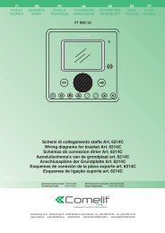
I Descrizione monitor e informazioni utente.<br />
GB Description of the monitor and user information.<br />
F<br />
Description des moniteurs et informations utilisateur.<br />
NL Beschrijving van de monitor en gebruikersinformatie.<br />
8<br />
4<br />
5<br />
6<br />
7<br />
9<br />
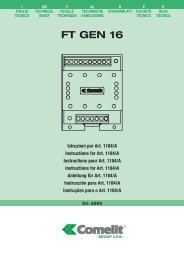
I Monitor Videocitofonici <strong>Comelit</strong> della serie Bravo Art 5702 (Monitor a colori),<br />
sono compatibili con i Monitor delle serie precedenti: Eurocom, Videocom, Diva.<br />
La staffa di fissaggio (Art. 5706) completa il Monitor e determina il sistema di<br />
cablaggio Semplificato.<br />
1. Selettore suoneria/servizio Privacy a 3 posizioni:<br />
Posizione sinistra: Suoneria volume massimo.<br />
Posizione centrale: Suoneria volume medio.<br />
Posizione destra : Attivazione funzione Privacy.<br />
(Per servizio Privacy si intende l’esclusione della chiamata dal posto<br />
esterno; l’attivazione della funzione Privacy è evidenziata dalla comparsa di<br />
un indicatore rosso a lato del selettore).<br />
2. Led di segnalazione (disponibile di serie).<br />
3. Pulsante Apriporta .<br />
4. Pulsante disponibile di serie, riferimento in morsettiera .<br />
(Solitamente utilizzato per funzione Autoaccensione).<br />
5. Pulsante disponibile di serie (riferimento in morsettiera P2C2).<br />
6. Pulsanti opzionali per attivazione funzioni supplementari (1)<br />
D<br />
P<br />
E<br />
1<br />
2<br />
3<br />
4<br />
5<br />
6<br />
Monitorbeschreibung und Anwenderhinweise.<br />
Descrição do monitor e informações ao usuário.<br />
Descripción monitor e informaciones usuario.<br />
10<br />
11<br />
<strong>MT</strong> <strong>KIT</strong> <strong>07</strong><br />
7. Pulsanti o Led opzionali per attivazione/visualizzazione funzioni<br />
supplementari (2)<br />
8. Schermo per visualizzazione immagine da posto esterno.<br />
9. Cartoncino intercambiabile e personalizzabile tramite Kit opzionale.<br />
10. Manopola regolazione luminosità (ruotare in senso orario per aumentare la<br />
luminosità).<br />
11. Manopola regolazione contrasto per monitor in bianco e nero o regolazione<br />
intensità colore per monitor a colori (ruotare in senso orario per aumentare<br />
il valore).<br />
12. Etichetta memo-pulsanti su cui è possibile riportare la funzione dei pulsanti<br />
del Monitor (da applicare sul Monitor sotto la cornetta come indicato in<br />
figura). L’etichetta adesiva è allegata ai Monitor Art. 5702 nel manuale utente<br />
FT BRAVO 01.<br />
13. Cornetta Monitor (Sollevare la cornetta per iniziare la comunicazione).<br />
(1) Pulsante disponibile con scheda opzionale Art. 5733.<br />
(2) Pulsante disponibile con scheda opzionale Art. 5733. Led di visualizzazione<br />
disponibile con scheda opzionale Art. 5734.<br />
1<br />
2<br />
3<br />
12<br />
13<br />
3 <strong>MT</strong> <strong>KIT</strong> <strong>07</strong>
<strong>MT</strong> <strong>KIT</strong> <strong>07</strong> 4<br />
GROUP S.P.A.<br />
The <strong>Comelit</strong> Videodoor entry Monitors in the Bravo series Art. 5702 (Colour<br />
Monitor), are compatible with the Monitors of the previous series: Eurocom,<br />
Videocom and Diva. The fixing bracket (Art. 5706) completes the Monitor and<br />
determines the Simplified cabling system.<br />
1. 3-position selector for Call tone/Privacy service.<br />
Left-hand position: Call tone at maximum volume.<br />
Central position: Call tone at medium volume.<br />
Right-hand position : Activation of Privacy service.<br />
2.<br />
(Privacy service means exclusion of the call from the external unit.<br />
Activation of the Privacy function is shown by a red indicator appearing<br />
on the left-hand side of the selector).<br />
Signalling LED (available as standard).<br />
3. Door-opening pushbutton .<br />
4. Pushbutton available as standard, reference in terminal board<br />
(Normally used for Self-lighting function).<br />
.<br />
5. Pushbutton available as standard (reference in terminal board P2C2).<br />
6. Optional pushbuttons to activate additional functions (1) .<br />
7. Optional pushbuttons or LEDs to activate/display additional functions (2) GB NL<br />
.<br />
8. Screen for viewing the image from the external unit.<br />
9. Label which can be interchanged and personalised using an optional Kit.<br />
10. Brightness adjustment knob (turn clockwise to increase brightness).<br />
11. Control for contrast setting for black and white Monitor or colour intensity<br />
control for colour Monitor (turn clockwise to increase the value).<br />
12. Pushbutton memo label where the Monitor pushbutton functions can be<br />
indicated (to be applied to the Monitor under the handset as shown in the<br />
figure).<br />
The adhesive label is enclosed with Monitors Art. 5702 in the FT BRAVO<br />
01 user manual.<br />
13. Monitor handset (Lift the handset to start communication).<br />
F<br />
(1) Pushbutton available with supplementary card Art. 5733.<br />
(2) Pushbutton available withsupplementarycard Art. 5733. Display LED<br />
available with supplementary card Art. 5734.<br />
Les moniteurs des visiophones <strong>Comelit</strong> de la série Bravo Art. 5702 (moniteur<br />
couleur) sont compatibles avec les moniteurs des séries précédentes: Eurocom,<br />
Videocom et Diva. La bride de fixation (Art. 5706) complète le moniteur et elle<br />
détermine le système de câblage simplifié.<br />
1. Sélecteur sonnerie/service Privacy à 3 positions.<br />
Position à gauche: Sonnerie volume maximum.<br />
Position centrale: Sonnerie volume moyen.<br />
Position à droite : Activation du service Privacy.<br />
(Le Service Privacy exclut l’appel de la plaque de rue. L’activation de la<br />
fonction Privacy est indiquée par l’éclairage d’une led rouge sur le côté du<br />
sélecteur).<br />
2. Led de signalisation (disponible de série).<br />
3. Bouton Ouvre-porte .<br />
4. Bouton disponible de série, connexion sur le bornier de raccordement .<br />
(Normalement utilisé pour la fonction d’autoallumage).<br />
5. Bouton disponible de série (bornes de raccordement P2 / C2).<br />
6. Boutons en option pour activation fonctions supplémentaires (1) .<br />
7. Boutons ou leds en option pour activation/affichage fonctions<br />
supplémentaires (2) .<br />
8. Écran de visualisation du moniteur.<br />
9. Carton interchangeable et personnalisable au moyen du kit en option.<br />
10. Bouton de réglage de la luminosité (tourner dans le sens des aiguilles d’une<br />
montre pour augmenter la luminosité).<br />
11. Réglage du contraste pour Moniteur en noir et blanc ou réglage de l'intensité<br />
de la couleur pour Moniteur en couleurs (tourner en sens horaire pour<br />
augmenter la valeur).<br />
12. Étiquette mémo-boutons sur laquelle on peut indiquer la fonction des boutons<br />
du Moniteur (à appliquer au moniteur sous le récepteur, de la manière<br />
indiquée dans la figure). L’étiquette autocollante est annexée aux moniteurs<br />
Art. 5702 dans le manuel de l’utilisateur FT BRAVO 01.<br />
13. Récepteur Moniteur (Soulever le récepteur pour commencer la<br />
communication).<br />
(1) Bouton disponible avec la carte en option Art. 5733.<br />
(2) Bouton disponible avec la carte en option Art. 5733. Led de visualisation<br />
disponible avec la carte en option Art. 5734.<br />
D<br />
De video-intercommonitoren van <strong>Comelit</strong> van de Bravo-serie, Art. 5702 (met<br />
kleurenmonitor), zijn compatibel met de monitoren van de eerdere series:<br />
Eurocom, Videocom en Diva. De grondplaat (Art. 5706) completeert de<br />
monitor en is geschikt voor het vereenvoudigde bekabelingssysteem.<br />
1. Keuzeschakelaar Beltoon / Privacy-functie met 3 standen:<br />
Links: maximaal volume beltoon.<br />
Midden: normaal volume beltoon.<br />
Rechts : inschakeling Privacy-functie.<br />
(Onder Privacy-functie wordt verstaan, het uitschakelen van de oproep vanaf<br />
het entreepaneel of vanaf de portierscentrale; wanneer de Privacy-functie<br />
actief is, is het linker rode gedeelte van de keuzeschakelaar zichtbaar).<br />
2. LED (standaard aanwezig).<br />
3. Deuropener .<br />
4. Drukknop, standaard aanwezig (referentie in het aansluitblok: ).<br />
(Wordt alleen gebruikt voor de functie Beeldoproep).<br />
5. Drukknop, standaard aanwezig (referentie in het aansluitblok: P2C2).<br />
6. Optionele drukknoppen voor inschakeling van extra functies (1) .<br />
7. Optionele drukknoppen of LED's voor inschakeling/weergave van extra<br />
functies (2) .<br />
8. Scherm voor weergave van het beeld vanaf het entreepaneel.<br />
9. Verwisselbaar front, kan naar persoonlijke voorkeur vervangen worden door<br />
een ander front uit de kit met optionele fronten.<br />
10. Knop voor instelling van de helderheid (rechtsom draaien om de lichtsterkte<br />
te verhogen).<br />
11. Instelling voor contrast bij zwart-wit monitor of kleurverzadiging bij<br />
kleurenmonitor (draai in de richting van de klok voor het verhogen van de<br />
waarde).<br />
12. Memosticker voor het noteren van de functies van de monitorknoppen (op<br />
de monitor, onder de hoorn, aan te brengen zoals in de afbeelding getoond).<br />
De stickers voor de monitoren Art. 5702 worden meegeleverd met de<br />
gebruikershandleiding FT BRAVO 01.<br />
13. Hoorn van de monitor (de hoorn opnemen om een gesprek te voeren).<br />
(1) Drukknop, beschikbaar na installatie van de optionele kaart Art. 5733.<br />
(2) Drukknop, beschikbaar na installatie van de optionele kaart Art. 5733.<br />
LED, beschikbaar na installatie van de optionele kaart Art. 5734.<br />
Die Monitore für Video-Gegensprechanlagen <strong>Comelit</strong> der Reihe Bravo Art. 5702<br />
(Farbmonitor) sind mit den Monitoren der vorherigen Reihen Eurocom, Videocom<br />
und Diva kompatibel. Der Befestigungssockel (Art. 5706) vervollständigt den<br />
Monitor und bestimmt das vereinfachte Verkabelungssystem.<br />
1. Wahlschalter Klingelton/Privacy-Funktion mit 3 Stellungen:<br />
Linke Stellung: Maximale Lautstärke.<br />
Mittlere Stellung: Mittlere Lautstärke.<br />
Rechte Stellung : Aktivierung Funktion Privacy.<br />
(Mit Privacy-Funktion ist die Deaktivierung des Rufs von der Außenstelle<br />
oder der Portierförtnerzentrale gemeint; die Aktivierung der Privacy-<br />
Funktion wird durch das Einschalten einer roten Anzeige auf der Seite des<br />
Wahlschalters angezeigt).<br />
2. Anzeige-LED (serienmäßig verfügbar).<br />
3. Türöffnertaste .<br />
4. Taste serienmäßig verfügbar, Referenz in Klemmleiste .<br />
(Verwendung ausschließlich für Funktion Selbsteinschaltung).<br />
5. Taste serienmäßig verfügbar (Referenz in Klemmleiste P2C2).<br />
6. Optionale Tasten für Aktivierung Zusatzfunktionen (1) .<br />
7. Optionale Tasten oder LEDs für Aktivierung/Anzeige Zusatzfunktionen (2) .<br />
8. Bildschirm für Anzeige Bilder von der Außenstelle.<br />
9. Auswechselbarer und mittels Zusatzkit anpassbarer Karton.<br />
10. Helligkeitseinstellgriff (im Uhrzeigersinn drehen, um die Helligkeit zu erhöhen).<br />
11. Kontrastsregler für Schwarzweiß-Monitor oder Farbschärferegler für Farb-<br />
Monitor (im Uhrzeigersinn drehen, um den Wert zu erhöhen) .<br />
12. Kennzeichnungsetikett für Tasten, auf diesem können die Tastenfunktionen<br />
des Monitors wiedergegeben werden (wird auf dem Monitor unter dem<br />
Hörer angebracht, wie in der Abbildung angegeben).<br />
Das Klebeetikett liegt den Monitoren Art. 5702 im Bedienerhandbuch FT<br />
BRAVO 01 bei.<br />
13. Hörer Monitor (den Hörer abnehmen, um mit der Kommunikation zu<br />
beginnen).<br />
(1) Taste verfügbar mit Zusatzkarte Art. 5733.<br />
(2) Taste verfügbar mit Zusatzkarte Art. 5733.<br />
Anzeige-LED verfügbar mit Zusatzkarte Art. 5734.
P<br />
E<br />
Os Monitores dos intercomunicadores de vídeo <strong>Comelit</strong> da série Bravo Art. 5702<br />
(Monitor a cores), são compatíveis com os Monitores das seguintes séries:<br />
Eurocom, Videocom, Diva. O suporte de fixação (Art. 5706) completa o Monitor<br />
e determina o sistema de cablagem simplificado.<br />
1. Selector campainha/serviço Privacy com 3 posições:<br />
Posição à esquerda: Campainha no volume máximo.<br />
Posição central: Campainha no volume médio.<br />
Posição à direita : Activação da função Privacy.<br />
(Por serviço Privacy entende-se a exclusão da chamada no posto externo ou<br />
na central auxiliar da portaria; a activação da função Privacy é assinalada<br />
pelo acendimento de um indicador vermelho no lado do selector).<br />
2. LED de sinalização (disponível de série).<br />
3. Botão de Abertura da porta .<br />
4. Botão disponível de série, referência na tira de terminais .<br />
(Apenas utilizado para a função de Acendimento automático).<br />
5. Botão disponível de série, (referência na tira de terminais P2C2).<br />
6. Botões opcionais para activação de funções suplementares (1) .<br />
7. Botões ou LED opcionais para activação/visualização de funções<br />
suplementares (2) .<br />
8. Ecrã para visualização de imagens do posto externo.<br />
9. Cartão intercambiável e personalizável através do Kit opcional.<br />
10. Manípulo de regulação da luminosidade (rodar no sentido dos ponteiros do<br />
relógio para aumentar a luminosidade).<br />
11. Control para ajuste de contraste no monitor Bravo a preto e branco , e da<br />
intensidade de côr no monotor Bravo a cores. (Rodar no sentido dos<br />
ponteiros do relógio para aumentar o valor).<br />
12. Etiqueta para os botões onde é possível indicar a função dos botões do Monitor<br />
(aplicar no Monitor debaixo do auscultador, tal como indicado na figura).<br />
A etiqueta autocolante é fornecida com o Monitor Art. 5702 no manual de<br />
utilizador FT BRAVO 01.<br />
13. Auscultador do Monitor (Levantar o auscultador para iniciar a<br />
comunicação).<br />
(1) Botão disponível com cartão opcional Art. 5733.<br />
(2) Botão disponível com cartão opcional Art. 5733. LED de visualização<br />
disponível com o cartão opcional Art. 5734.<br />
Los Monitores Vídeo porteros <strong>Comelit</strong> de la serie Bravo Art 5702 (Monitor en<br />
color), son compatibles con los monitores de series precedentes: Eurocom,<br />
Videocom, Diva. La placa de fijación (Art. 5706) completa el Monitor y determina<br />
el sistema de cableado Simplificado.<br />
1. Selector tono de llamada/servicio Privado de 3 posiciones:<br />
Posición izquierda: Tono de llamada volumen máximo.<br />
Posición central: Tono de llamada volumen medio.<br />
Posición derecha : Activación función servicio Privado.<br />
(Por el servicio Privado se entiende la exclusión de la llamada de la unidad<br />
externa o desde la central de portería; la activación de la función servicio<br />
Privado se muestra por la aparición de un indicador rojo en el lado izquierdo<br />
del selector).<br />
2. Led de señalización (disponible de serie).<br />
3. Pulsador Abre puerta .<br />
4. Pulsador disponible de serie, referencia en la caja de conexión .<br />
(Normalmente utilizado para función Autoencendido).<br />
5. Pulsador disponible de serie (referencia en la caja de conexión P2C2).<br />
6. Pulsadores opcionales para activación funciones suplementarias (1) .<br />
7. Pulsadores o Led opcionales para activación/visualización funciones<br />
suplementarias (2) .<br />
8. Pantalla para visualización imagen desde unidad externa.<br />
9. Etiqueta intercambiable y personalizable mediante Kit opcional.<br />
10. Manivela de regulación luminosidad (girar en sentido horario para aumentar<br />
la luminosidad).<br />
11. Potenciómetro de regulación del contraste para el monitor B/N o<br />
potenciómetro de regulación de intensidad para el monitor en COLOR (para<br />
regular girar en sentido horario).<br />
12. Etiqueta memo-pulsadores en las que es posible indicar la función de los<br />
pulsadores del Monitor (para aplicar en el Monitor debajo del auricular como<br />
se indica en la figura). La etiqueta adhesiva está conectada a los Monitores<br />
Art. 5702 en el manual usuario FT BRAVO 01.<br />
13. Auricular Monitor (Descolgar el auricular para empezar la comunicación).<br />
(1) Pulsador disponible con tarjeta opcional Art. 5733.<br />
(2) Pulsador disponible con tarjeta opcional Art. 5733.<br />
Led de visualización disponible con tarjeta opcional Art. 5734.<br />
<strong>MT</strong> <strong>KIT</strong> <strong>07</strong><br />
5 <strong>MT</strong> <strong>KIT</strong> <strong>07</strong>
145 cm<br />
<strong>MT</strong> <strong>KIT</strong> <strong>07</strong> 6<br />
GROUP S.P.A.<br />
CV2<br />
CV7<br />
CV1<br />
CV6<br />
CV3<br />
CV4<br />
CV5<br />
Fig. 1 Fig. 2 Fig. 3<br />
Fig. 4<br />
Fig. 6<br />
CV2<br />
CV7<br />
CV1<br />
CV6<br />
CV3<br />
CV4<br />
CV5<br />
1<br />
2<br />
3<br />
4<br />
5<br />
6<br />
2<br />
2<br />
1<br />
2<br />
3<br />
4<br />
5<br />
6<br />
1<br />
1<br />
CV2<br />
CV7<br />
CV1<br />
CV6<br />
CV3<br />
CV4<br />
CV5<br />
1<br />
2<br />
3<br />
4<br />
5<br />
6<br />
CV2<br />
CV7<br />
CV1<br />
CV6<br />
CV3<br />
CV4<br />
CV5<br />
1<br />
2<br />
3<br />
4<br />
5<br />
6<br />
14,4<br />
8,1<br />
Fig. 5<br />
3<br />
1,4<br />
3 6<br />
6<br />
1<br />
2<br />
3<br />
4<br />
5<br />
5<br />
10,2 11<br />
1,4<br />
1<br />
2<br />
3<br />
4<br />
5<br />
6<br />
2<br />
1<br />
2<br />
3<br />
4<br />
5<br />
6<br />
4<br />
4
I<br />
Fig. 7<br />
CV1<br />
CV3<br />
CV1<br />
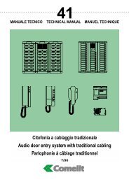
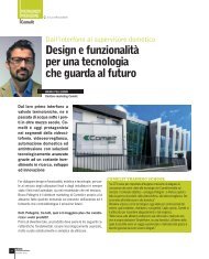
Fig. 1 Installazione Staffa Art. 5706 su scatola serie civile 503 (Art. 4517) *.<br />
Fig. 2 Installazione a muro Staffa Art. 5706 con 4 viti a tassello.<br />
Fig. 3 Misure di ingombro del Monitor in relazione ai punti di fissaggio della<br />
Staffa Art. 5706.<br />
Fig. 4 Procedura di aggancio Monitor.<br />
Fig. 5 Procedura per togliere il Monitor dalla staffa a cui è agganciato.<br />
Fig. 6 Procedura per il montaggio del monitor sulla base da tavolo Art. 5712.<br />
Fig. 7 1. Connettore Staffa-Monitor.<br />
2. Morsetti di connessione impianto:<br />
LED1 Ingresso alimentazione Led di segnalazione (max 12V DC).<br />
+ - Ingresso di alimentazione Monitor positivo (+) e massa (-).<br />
V1 V2 Ingresso segnale Video differenziale.<br />
AI Morsetto di connessione per attivazione funzione opzionale<br />
autoaccensione interna (vedi esempi di connessione sugli schemi<br />
riportati nelle pagine seguenti).<br />
AS Ingresso ausiliario.<br />
S Ingresso suoneria elettronica e fonica.<br />
4 Negativo fonica.<br />
Contatti NO (24V-100mA max) Pulsante 1 del Monitor.<br />
P2 C2 Contatti NO (24V-100mA max) Pulsante 2 del Monitor.<br />
3. CV1_V1 CV1_V2 Ponticelli per la chiusura 75 ohm del segnale video,<br />
da tagliare in caso di collegamento in cascata come da schema V5/BB<br />
riportato a pagina 12.<br />
4. CV3 Ponticello da tagliare per impedire l’accensione automatica del<br />
Monitor su chiamata da posto esterno.<br />
5. Spazio per alloggiamento morsettiera scheda opzionale Art. 5733 o<br />
Art. 5734. Per maggiori informazioni vedi FT/GEN/17).<br />
* Utilizzare eventualmente 4 viti a tassello per migliorare il fissaggio<br />
della staffa.<br />
4<br />
2<br />
3<br />
1<br />
5<br />
GB<br />
F<br />
<strong>MT</strong> <strong>KIT</strong> <strong>07</strong><br />
Fig. 1 Installation of Bracket Art. 5706 on civil series 503 box (Art. 4517) *.<br />
Fig. 2 Installation on wall with Bracket Art. 5706 with 4 expansion anchoring<br />
screws.<br />
Fig. 3 Overall dimensions of the Monitor in relation to the fixing points of<br />
Bracket Art. 5706.<br />
Fig. 4 Procedure for mounting monitor to the bacjkplate.<br />
Fig. 5 Procedure for removing the Monitor from the Bracket it is hooked up to.<br />
Fig. 6 Operations to follow in order to assemble the monitor on the desk base<br />
Art. 5712.<br />
Fig. 7 1. Bracket-Monitor connector.<br />
2. Terminals for system connection:<br />
LED1 Power supply input signalling LED (max 12V DC).<br />
+ - Input of Monitor power supply positive (+) and ground (-).<br />
V1 V2 Differential Video signal input.<br />
AI Connection terminal for activation of optional self-lighting function<br />
(see connection examples in the diagrams given on the following<br />
pages).<br />
AS Auxiliary input.<br />
S Input for electronic and sound call signal.<br />
4 Negative<br />
NO Contacts (24V-100mA max) Pushbutton 1 of the Monitor.<br />
P2 C2 NO Contacts (24V-100mA max) Pushbutton 2 of the Monitor.<br />
3. CV1_V1 CV1_V2 Bridges for 75 ohm closing of the video signal, to be<br />
cut in the case of cascade connection as per diagram V5/BB given on<br />
page 12.<br />
4. CV3 Bridge to be cut to prevent automatic lighting up of the Monitor<br />
on an external unit call.<br />
5. Space for housing terminal board optional card Art. 5733 or Art. 5734.<br />
For further information, please see FT/GEN/17).<br />
* 4 expasion anchoring screws can be used to improve Bracket fixing<br />
Fig. 1 Installation Bride Art. 5706 sur le boîtier série civile 503 (Art. 4517) *.<br />
Fig. 2 Installation en saillie Bride Art. 5706 à l’aide de 4 vis.<br />
Fig. 3 Dimensions d’encombrement du moniteur par rapport aux points de<br />
fixation de la Bride Art. 5706.<br />
Fig. 4 Procédure de mise en place du moniteur.<br />
Fig. 5 Procédure de retrait du moniteur de sa bride de fixation.<br />
Fig. 6 Procédé à suivre pour le montage du moniteur sur la base de table<br />
Art. 5712.<br />
Fig. 7 1. Connecteur bride-moniteur.<br />
2. Bornes de connexion à l’installation:<br />
LED1 Entrée alimentation led de signalisation (max 12V CC).<br />
+ - Entrée d’alimentation moniteur positif (+) et masse (-).<br />
V1 V2 Entrée signal vidéo différentiel.<br />
AI Borne de connexion pour activation fonction en option fonction<br />
d’autoallumage intérieur (voir exemples de connexion dans les<br />
schémas indiqués aux pages suivantes).<br />
AS Entrée auxiliaire.<br />
S Entrée sonnerie électronique et phonique<br />
4 Négatif phonie.<br />
Contacts NO (24V-100mA max) Bouton 1 du moniteur.<br />
P2 C2 Contacts NO (24V-100mA max) Bouton 2 du moniteur.<br />
3. CV1_V1 CV1_V2 Pont pour la fermeture 75 Ohms du signal vidéo, à<br />
couper en cas de connexion en cascade conformément au schéma<br />
V5/BB indiqué page 12.<br />
4. CV3 Pont à couper pour empêcher l’allumage automatique du<br />
moniteur à l’appel de la plaque de rue.<br />
5. Emplacement pour loger la boîte à bornes carte en option Art. 5733<br />
ou Art. 5734. Pour plus d’informations voir FT/GEN/17).<br />
* Utiliser éventuellement 4 vis à tampon pour améliorer le fixage de l'étrier.<br />
7 <strong>MT</strong> <strong>KIT</strong> <strong>07</strong>
NL<br />
D<br />
<strong>MT</strong> <strong>KIT</strong> <strong>07</strong> 8<br />
GROUP S.P.A.<br />
Fig. 1 Installatie van de grondplaat Art. 5706 op de inbouwdoos van de serie 503<br />
(Art. 4517) *.<br />
Fig. 2 Installatie van de grondplaat Art. 5706 tegen de wand met 4 plugschroeven.<br />
Fig. 3 Afmetingen van de monitor en positie van de bevestigingspunten op de<br />
grondplaat Art. 5706.<br />
Fig. 4 Wijze van bevestiging van de monitor.<br />
Fig. 5 Wijze waarop de monitor van de grondplaat wordt afgenomen.<br />
Fig. 6 Instructies voor het monteren van de monitor op de bureausteun 5712.<br />
Fig. 7 1. Connector voor grondplaat van monitor.<br />
2. Aansluitklemmen voor de installatie:<br />
LED1 Ingang voor voeding van de LED (max. 12V DC).<br />
+ - Ingang voor voeding van de monitor plus (+) en massa (-).<br />
V1 V2 Ingang voor differentieel videosignaal.<br />
AI Aansluitklem voor activering van de optionele functie Beeldoproep<br />
vanuit de woning (zie de aansluitvoorbeelden in de schema's op de<br />
volgende pagina's).<br />
AS Ingang voor extra functies.<br />
S Ingang voor elektronische bel en spreekgedeelte.<br />
4 Min van spreekgedeelte.<br />
NO-contacten (24V-100 mA max.) Drukknop 1 van de monitor.<br />
P2 C2 NO-contacten (24V-100 mA max.) Drukknop 2 van de monitor<br />
3. CV1_V1 CV1_V2 Draadbruggen voor afsluiten 75 ohm-videosignaal;<br />
door te knippen voor aansluiting in cascade zoals aangegeven in het<br />
schema V5/BB op pagina 12.<br />
4. CV3 Draadbrug, door te knippen om automatische inschakeling van<br />
de monitor bij aanbellen op het entreepaneel te voorkomen.<br />
5. Ruimte voor installatie aansluitblok van optionele kaart Art. 5733 of<br />
Art. 5734. Raadpleeg FT/GEN/17 voor meer informatie<br />
* De 4 schroeven en pluggen kunnen worden gebruikt om de<br />
grondplaat steviger aan de muur te bevestigen.<br />
Abb. 1 Installation Sockel Art. 5706 auf Wohnbaugehäuse 503 (Art. 4517) *.<br />
Abb. 2 Wandinstallation der Sockel Art. 5706 mit 4 Dübeln.<br />
Abb. 3 Außenabmessungen des Monitors hinsichtlich der Befestigungspunkte<br />
des Sockels Art. 5706.<br />
Abb. 4 Montagevorgang des Monitors.<br />
Abb. 5 Vorgehensweise zur Demontage des Monitors vom Sockel an dem er<br />
befestigt ist.<br />
Abb. 6 Arbeitsschritte um den Monitor in die Tischgrundplatte 5712 zu montieren.<br />
Abb. 7 1. Verbinder Sockel-Monitor.<br />
2. Verbindungsklemmen Anlage:<br />
LED1 Eingang Versorgungsspannung Anzeige-LED (max. 12V DC).<br />
+ - Versorgungseingang Monitor Plus (+) und Minus (-).<br />
V1 V2 Eingang Videosignal differential.<br />
AI Verbindungsklemme für Aktivierung optionale Funktion interne<br />
Selbsteinschaltung (siehe Anschlussbeispiele auf den Schemata der<br />
folgenden Seiten).<br />
AS Hilfseingang<br />
S Eingang Audio, elektronischer Ruf, Türöffners.<br />
4 Minus, gemeinsamer Draht.<br />
Kontakte NO (24V-100mA max) Taste 1 des Monitors.<br />
P2 C2 Kontakte NO (24V-100mA max) Taste 2 des Monitors.<br />
3. CV1_V1 CV1_V2 BrückeJumper für Abschluss 75 Ohm des<br />
Videosignals. Muss bei Kaskadenschaltung, wie im Schema V5/BB<br />
auf Seite 12 abgeschnitten werden.<br />
4. CV3 abzuschneidender BrückeJumper, um die automatische<br />
Einschaltung des Monitors bei Ruf von Außenstelle zu verhindern.<br />
5. Leerplatz für Montage Klemmleiste Zusatzkarte Art. 5733 oder Art.<br />
5734. Für weitere Informationen siehe FT/GEN/17.<br />
* 4 Befestigungsschrauben zur Fixierung der Klammern<br />
P<br />
E<br />
Fig. 1 Instalação do Suporte Art. 5706 na caixa da série civil 503 (Art. 4517). *<br />
Fig. 2 Instalação mural do Suporte Art. 5706 com 4 parafusos de encastre.<br />
Fig. 3 Medição das dimensões do Monitor em relação aos pontos de fixação do<br />
Suporte Art. 5706.<br />
Fig. 4 Procedimento de fixação do Monitor.<br />
Fig. 5 Procedimento para retirar o Monitor do suporte ao qual está engatado.<br />
Fig. 6 Procedimentos a seguir para montar o monitor na base de mesa<br />
Art. 5712.<br />
Fig. 7 1. Conector Suporte-Monitor.<br />
2. Terminais de conexão da instalação:<br />
LED1 Entrada de alimentação do LED de sinalização (máx. 12V DC).<br />
+ - Entrada de alimentação do Monitor positivo (+) e massa (-).<br />
V1 V2 Entrada de sinal de Vídeo diferencial.<br />
AI No terminal de conexão para activação da função opcional de<br />
acendimento automático interno (consultar os exemplos de conexão<br />
nos esquemas indicados nas páginas a seguir).<br />
AS Entrada auxiliar.<br />
S Entrada da campainha electrónica e acústica.<br />
4 Negativo da acústica.<br />
Contactos NO (24V-100mA máx.) Botão 1 do Monitor.<br />
P2 C2 Contactos NO (24V-100mA máx.) Botão 2 do Monitor.<br />
3. CV1_V1 CV1_V2 Jumpers para o fecho 75 ohm do sinal de vídeo, a<br />
cortar em caso de ligação em cascada, como indicado no esquema<br />
V5/BB na página 12.<br />
4. CV3 Jumper a cortar para impedir o acendimento automático do<br />
Monitor em caso de chamada no posto externo.<br />
5. Espaço para o alojamento da tira de terminais no cartão opcional Art.<br />
5733 ou Art. 5734. Para mais informações, consultar FT/GEN/17).<br />
* 4 parafusos de ancoragem podem ser usados para melhorar a<br />
fixação da Base<br />
Fig. 1 Instalación Placa soporte Art. 5706 en caja serie civil 503 (Art. 4517) *.<br />
Fig. 2 Instalación de muro Placa soporte Art. 5706 con 4 tornillos con taco.<br />
Fig. 3 Dimensiones del Monitor con respecto a los puntos de fijación de la<br />
placa soporte Art. 5706.<br />
Fig. 4 Procedimiento de enganche Monitor.<br />
Fig. 5 Procedimiento para extraer el Monitor de la placa soporte a la que está<br />
enganchado.<br />
Fig. 6 Operaciones a seguir para el montaje del monitor en el soporte de<br />
sobremesa Art. 5712.<br />
Fig. 7 1. Conector Placa soporte -Monitor.<br />
2. Bornas conexión instalación:<br />
LED1 Entrada alimentación Led de señalización (máx. 12V DC).<br />
+ - Entrada de alimentación Monitor positivo (+) y masa (-).<br />
V1 V2 Entrada señal Vídeo diferencial.<br />
AI Borna de conexión para activación opcional función opcional<br />
autoencendido interno (véase ejemplos de conexión en los esquemas<br />
indicados en las páginas siguientes).<br />
AS Entrada auxiliar.<br />
S Entrada tono de llamada electrónica y fónica.<br />
4 Negativo fónica.<br />
Contactos NO (24V-100mA máx.) Pulsador 1 del Monitor.<br />
P2 C2 Contactos NO (24V-100mA máx.) Pulsador 2 del Monitor.<br />
3. CV1_V1 CV1_V2 Puentes para el cierre 75 ohm de la señal vídeo,<br />
para cortar en caso de conexión en cascada como en el esquema<br />
V5/BB indicado en la página 12.<br />
4. CV3 Puente para cortar, para impedir el encendido automática del<br />
Monitor en llamada desde la unidad externa.<br />
5. Espacio para conexión caja de conexión tarjeta opcional Art. 5733 o<br />
Art. 5734. Para mayores informaciones véase FT/GEN/17)<br />
* Utilizar los 4 tornillos para una mejor fijación de la caja
I Altezza scatola incasso.<br />
GB How to recess the flush-mounted box.<br />
F Comment placer la boîtes d’ encastrement dans le mur.<br />
NL Hoogte van de inbouwdoos.<br />
D Montage der UP-Dose.<br />
P Altura da caixa de embutir.<br />
E Altura caja de empotrar.<br />
160 - 165 cm<br />
I Fissaggio del telaio su custodia da parete.<br />
GB How to fix the frame on the surface housing.<br />
F Comment fixer le cadre au boîtier saillie.<br />
NL Bevestiging van het frame op de opbouwbehuizing.<br />
D Befestigung des Rahmens am Aufputzgehäuse.<br />
P Fixação do quadro na protecção de parede.<br />
E Fijación del armazón en caja de pared.<br />
I Fissaggio del telaio su scatola da incasso.<br />
GB How to fix the frame on the flush-mounted box.<br />
F Comment fixer le cadre à la boîte d’ encastrement.<br />
NL Bevestiging van het frame op de inbouwdoos.<br />
D Befestigung des Rahmens an der UP-Dose.<br />
P Fixação do quadro na caixa de embutir.<br />
E Fijación del armazón en caja empotrable.<br />
<strong>MT</strong> <strong>KIT</strong> <strong>07</strong><br />
I Cablaggio morsettiera inserita o estratta.<br />
GB Cabling of terminal block when fitted or not fitted.<br />
F Câblage du bornier déjà inséré ou à insérer.<br />
NL<br />
Bekabeling van aansluitblok, ingedrukt of uitgetrokken.<br />
D Verdrahtung der Anschlußklemmen.<br />
P Cablagem de tira de terminais inserida ou saliente.<br />
E Cableado caja de bornas introducida o extraída.<br />
9 <strong>MT</strong> <strong>KIT</strong> <strong>07</strong>
GROUP S.P.A.<br />
I Montaggio, collegamenti e regolazioni gruppo audio-video.<br />
GB Mounting, connection and adjusting of audio/video group.<br />
F Montage, connections et réglages du groupe audio/vidéo.<br />
NL Montage, aansluiting en instelling van het A/V-systeem.<br />
D Montage, Anschluß und Einstellung der Audio/Videogruppe.<br />
P Montagem, ligações e regulações do grupo áudio-vídeo.<br />
E Montaje, conexiones y regulaciones grupo audio –vídeo.<br />
I Montaggio /Smontaggio frontalini.<br />
GB How to insert and remove front panels.<br />
F Comment insérer et enlever les platines.<br />
NL Aanbrengen / afnemen van fronten.<br />
D Einbau und entfernen der Frontplatten.<br />
P Montagem / desmontagem das molduras.<br />
E Montaje / Desmontaje placas.<br />
<strong>MT</strong> <strong>KIT</strong> <strong>07</strong> 10<br />
+ -<br />
MIC<br />
+ -<br />
I Inserimento moduli.<br />
GB How to insert modules.<br />
F Comment insérer les modules.<br />
NL Plaatsing van de modules.<br />
D Einbau der Module.<br />
P Introdução dos módulos.<br />
E Introducción módulos.<br />
I Fissaggio cornice.<br />
GB How to fix the frame.<br />
F Commet fixer le châssis.<br />
NL<br />
Bevestigen van de omlijsting.<br />
D Fixierung des Rahmens.<br />
P Fixação do caixilho.<br />
E Fijación marco.<br />
1<br />
3<br />
2<br />
360˚
Fig. 1<br />
Utilizzare l’Art. opzionale 1234 “Kit stampa cartellini portanome Powercom” contenente<br />
20 fogli in poliestere e floppy disk con software dedicato per la corretta<br />
formattazione e stampa delle etichette (Fig. 2). Il software è anche liberamente<br />
scaricabile dal sito www.comelit.it<br />
ATT.NE: per un risultato perfetto e duraturo utilizzare una stampante laser.<br />
Use the optional art. 1234, kit for Powercom labels, which comprises of 20 polyester<br />
A4 sheets and a floppy disk with software necessary for the correct format<br />
and printing of the Powercom labels (see picture 2). The software can also<br />
be downloaded from our web site www.comelit.it. ATTENTION : for a perfect<br />
outcome of the labels we recommend the use of a laser printer.<br />
Utiliser l’Art. optionnel 1234 "Kit pour imprimer les étiquettes porte-noms Powercom",<br />
qui contient 20 feuilles A4 en polyester et une disquette avec un logiciel pour le correcte<br />
formatage et impression des étiquettes (voir figure 2). Le logiciel peut aussi être<br />
déchargé de notre site web www.comelit.it. ATTENTION : pour obtenir un résultat<br />
parfait et qui dur dans le temps, utiliser une imprimante Laser.<br />
Gebruik de optionele kit 1234 voor Powercom labels, welke bestaat uit 20<br />
polyester A4 velletjes en een floppydisk met software om de Powercom labels in<br />
het juiste formaat uit te printen (zie figuur 2) De software kan ook gedownload<br />
worden van onze website www.comelit.it. ATTENTIE: Het beste resultaat<br />
wordt behaald door de labels af te drukken met een laserprinter.<br />
Fig. 2<br />
Rossi<br />
Aldo<br />
Rossi<br />
Aldo<br />
Rossi<br />
Aldo<br />
<strong>MT</strong> <strong>KIT</strong> <strong>07</strong><br />
I Per una ottimale realizzazione dei cartellini portanome si consiglia di procedere in uno dei seguenti modi:<br />
GB There are 2 alternative ways to create and change names on the labels:<br />
F Pour réaliser les étiquettes porte-noms d’une façon optimale nous vous conseillons de procéder dans une des deux manières suivantes:<br />
NL Er zijn 2 manieren om namen of nummers op de labels te maken:<br />
D Für eine perfekte Realisierung der Namensschilder wird empfohlen, wie folgt vorzugehen:<br />
P Para uma colocação ideal dos porta-etiquetas, recomenda-se um dos seguintes métodos:<br />
E Para una óptima realización de las tarjetas porta nombre es aconsejable proceder de una de las siguientes maneras:<br />
I Utilizzare una striscia adesiva trasparente per etichettatrice (tipo Dimo) come mostrano in (Fig. 1).<br />
GB Use a transparent line sticker for labelling machines ( such as a Dymo) as shown in picture 1.<br />
F Utiliser une bande adhésive transparente pour machines à étiqueter ( type Dymo) comme montré dans la figure 1.<br />
NL Gebruik een labelprinter met transparante tape (bijvoorbeeld een Dymo), zoals afgebeeld in figuur 1.<br />
D Einen transparenten Klebestreifen für Etikettiermaschinen (Typ Dimo), wie (in Abb. 1) dargestellt verwenden.<br />
P Utilizar uma fita adesiva transparente para etiquetas (tipo Dino) como ilustrado na (Fig. 1).<br />
E Utilizar una banda adhesiva transparente para etiquetar (tipo Dimo) como muestran en (Fig.1).<br />
I<br />
GB<br />
F<br />
NL<br />
Rossi<br />
Aldo<br />
D<br />
P<br />
E<br />
Rossi<br />
Aldo<br />
Den optionalen Art. 1234 „Kit Druck Namensschilder Powercom“ mit 20<br />
Polyesterfolien und Diskette mit Software für die richtige Formatierung und den<br />
Druck der Etiketten verwenden (Abb. 2). Die Software kann auch kostenlos von<br />
der Internetseite www.comelit.it herunter geladen werden. ACHTUNG: Für ein<br />
perfektes und lang anhaltendes Druckergebnis wird die Verwendung eines<br />
Laserdruckers empfohlen.<br />
ATT.NE: per un risultato perfetto e duraturo utilizzare una stampante laser.<br />
Utilizar o Art. opcional 1234 “Kit de porta-etiquetas Powercom” com 20 folhas de<br />
poliéster e disquete com software concebido para a formatação e impressão<br />
das etiquetas (FIG. 2). O software também pode ser transferido gratuitamente<br />
em www.comelit.it.<br />
Atenção: para um resultado perfeito e duradouro, utilizar uma impressora<br />
a laser.<br />
Utilizar el Art. opcional 1234 “Kit imprime tarjetas porta nombre Powercom”con<br />
20 hojas de poliéster y disco floppy con software específico para el correcto formato<br />
e impresión de las etiquetas (Fig.2). El software también se puede descargar<br />
desde el sitio www.comelit.it<br />
ATT.NE: para un resultado perfecto y duradero utilizar una impresora láser.<br />
11 <strong>MT</strong> <strong>KIT</strong> <strong>07</strong>
GROUP S.P.A.<br />
I Impianto base 1 ingresso <strong>KIT</strong> 8176.<br />
GB Basic system with 1 entrance <strong>KIT</strong> 8176.<br />
F Installation de base 1 entrée <strong>KIT</strong> 8176.<br />
NL Basissysteem met 1 entree <strong>KIT</strong> 8176.<br />
D Basis-System 1 Eingang <strong>KIT</strong> 8176.<br />
P Equipamento base 1 entrada <strong>KIT</strong> 8176.<br />
E Instalación base 1 entrada <strong>KIT</strong> 8176.<br />
<strong>MT</strong> <strong>KIT</strong> <strong>07</strong> 12<br />
KBC/01A<br />
Conduttori<br />
Conductors<br />
Conducteurs<br />
Leitung<br />
Leiders<br />
Condutores<br />
Conductores<br />
0 ~ 12 ~<br />
+ - Bravo<br />
m<br />
20<br />
0,30<br />
6/10<br />
1,50<br />
14/10<br />
0,80<br />
10/10<br />
m<br />
50<br />
0,50<br />
8/10<br />
1,00<br />
12/10<br />
m<br />
100<br />
0,80<br />
10/10<br />
Cavo “twistata<br />
Twisted pair<br />
Paire tèlephonique torsadé<br />
m<br />
200<br />
1,00<br />
12/10<br />
1,50 2,00<br />
14/10 16/10<br />
0,28<br />
6/10<br />
mm 2<br />
ø<br />
mm 2<br />
ø<br />
mm 2<br />
ø<br />
mm 2<br />
ø
I Impianto 2 ingressi.<br />
GB System with 2 entrances.<br />
F Installation à deux entrées.<br />
NL Systeem met 2 entrees.<br />
KBC/02<br />
D<br />
P<br />
E<br />
Anlage 2 Eingänge.<br />
Equipamento com 2 entradas.<br />
Instalación 2 entradas.<br />
Conduttori<br />
Conductors<br />
Conducteurs<br />
Leitung<br />
Leiders<br />
Condutores<br />
Conductores<br />
0 ~ 12 ~<br />
+ - Bravo<br />
<strong>MT</strong> <strong>KIT</strong> <strong>07</strong><br />
m<br />
20<br />
0,30<br />
6/10<br />
1,50<br />
14/10<br />
0,80<br />
10/10<br />
m<br />
50<br />
0,50<br />
8/10<br />
1,00<br />
12/10<br />
m<br />
100<br />
0,80<br />
10/10<br />
Cavo “twistata<br />
Twisted pair<br />
Paire tèlephonique torsadé<br />
m<br />
200<br />
1,00<br />
12/10<br />
1,50 2,00<br />
14/10 16/10<br />
0,28<br />
6/10<br />
mm 2<br />
ø<br />
mm 2<br />
ø<br />
mm 2<br />
ø<br />
mm 2<br />
ø<br />
13 <strong>MT</strong> <strong>KIT</strong> <strong>07</strong>
GROUP S.P.A.<br />
I Schema base con telecamera remota aggiuntiva.<br />
GB Basic system with a supplementary remote videocamera.<br />
F Système de base avec une caméra supplémentaire déportée.<br />
NL Basis systeem met een extra videocamera.<br />
<strong>MT</strong> <strong>KIT</strong> <strong>07</strong> 14<br />
KBC/03<br />
D<br />
P<br />
E<br />
Basissystem mit Erweiterung für fernbedienbare Videokamera.<br />
Sistema básico com câmara suplementar remota.<br />
Esquema con telecamara externa.<br />
Conduttori<br />
Conductors<br />
Conducteurs<br />
Leitung<br />
Leiders<br />
Condutores<br />
Conductores<br />
0 ~ 12 ~<br />
+ - Bravo<br />
m<br />
20<br />
0,30<br />
6/10<br />
1,50<br />
14/10<br />
0,80<br />
10/10<br />
m<br />
50<br />
0,50<br />
8/10<br />
1,00<br />
12/10<br />
m<br />
100<br />
0,80<br />
10/10<br />
Cavo “twistata<br />
Twisted pair<br />
Paire tèlephonique torsadé<br />
m<br />
200<br />
1,00<br />
12/10<br />
1,50 2,00<br />
14/10 16/10<br />
0,28<br />
6/10<br />
mm 2<br />
ø<br />
mm 2<br />
ø<br />
mm 2<br />
ø<br />
mm 2<br />
ø
I Espansione kit 8176 con più utenze.<br />
GB <strong>KIT</strong> 8176 expansion with more users.<br />
F<br />
Kit 8176 avec extension de plusieurs usagers.<br />
NL 8176 <strong>KIT</strong> uitbreiding met meer gebruikers.<br />
V5/01BC/A<br />
D<br />
P<br />
E<br />
8176 <strong>KIT</strong> - Erweiterung für mehr Teilnehmer.<br />
Expansão do <strong>KIT</strong> 8176 com mais utilizadores.<br />
Ampliación del Kit 8176 con mas usuarios.<br />
<strong>MT</strong> <strong>KIT</strong> <strong>07</strong><br />
15 <strong>MT</strong> <strong>KIT</strong> <strong>07</strong>
GROUP S.P.A.<br />
I Collegamento di 1 citofono in parallelo.<br />
GB Parallel conection of additional telephone.<br />
F<br />
Connexion en parallèle d’un téléphone.<br />
NL Parallelle aansluiting van 1 audio toestel.<br />
I Aggiunta monitor BRAVO in parallelo (collegamento in derivazione).<br />
GB Additional BRAVO monitor in parallel (branched connection).<br />
F Adjonction d’un moniteur BRAVO en parallèle (câblage en dérivation).<br />
NL Extra aangesloten BRAVO monitor (ster schakeling).<br />
<strong>MT</strong> <strong>KIT</strong> <strong>07</strong> 16<br />
KBC/C<br />
D<br />
P<br />
E<br />
KBC/B<br />
D<br />
P<br />
E<br />
Parallelschaltung einer Innenstelle.<br />
1 telefone em conecção paralela.<br />
Instalación de 1 teléfono en paralelo.<br />
Zusätzlicher BRAVO Monitor in sternförmiger Schaltung.<br />
Monitor suplementar BRAVO em paralelo (conecção em estrela).<br />
Añadir monitor BRAVO en paralelo (instalación en derivación).
I Aggiunta monitor BRAVO in parallelo (collegamento in cascata).<br />
GB Additional BRAVO monitor in parallel (cascade connection).<br />
F<br />
Adjonction d’un moniteur BRAVO en parallèle (câblage en cascade).<br />
NL Extra aangesloten BRAVO monitor (cascade aansluiting, doorlussen).<br />
D Zusätzlicher BRAVO Monitor in Prallelschaltung.<br />
P Monitor suplementar BRAVO em paralelo (conecção em cascata).<br />
E Añadir monitor BRAVO en paralelo (instalación en cascada).<br />
KBC/A<br />
V5/BE<br />
I Per impedire l’accensione automatica da chiamata da posto esterno, tagliare il ponticello CV3.<br />
GB To prevent the monitor turning on upon a call from the entrance, cut the CV3 connection bridge<br />
F Afin d’éviter l’autoallumage du moniteur a l'appel depuis le poste extérieur, couper le pont CV3.<br />
NL Om te voorkomen dat de monitor aan gaat bij een oproep vanuit het entreepaneel dient de brug CV3 doorgeknipt te worden.<br />
D Um das Einschalten des Monitors beim Ruf von der Torstelle zu verhindern, muß man die Brücke CV3 auftrennen.<br />
P Para impedir a ligação automática de chamada pelo ponto externo, cortar o conector CV3.<br />
E Para impedir el encendido automatico de la llamada desde la unidad externa, cortar el puente CV3.<br />
<strong>MT</strong> <strong>KIT</strong> <strong>07</strong><br />
17 <strong>MT</strong> <strong>KIT</strong> <strong>07</strong>
GROUP S.P.A.<br />
I Utilizzo per usi vari del pulsante 2 e LED.<br />
GB Use of pushbutton 2 and LED for various uses.<br />
F<br />
Utilisation pour usages divers du bouton 2 et LED.<br />
NL Gebruik voor verschillende functies van drukknop 2 en LED.<br />
D Einsatz der Taste 2 und LED für verschiedene Zwecke.<br />
P Uso para vários fins do botão 2 e LED.<br />
E Utilización para diferentes usos del pulsador 2 y LED.<br />
<strong>MT</strong> <strong>KIT</strong> <strong>07</strong> 18<br />
V5/BF
15, Rue Jean Zay<br />
69800 Saint Priest<br />
Tel 04 72 28 06 56<br />
Fax 04 72 28 83 29<br />
http://www.comelit.fr<br />
E-mail: <strong>Comelit</strong>.NH@wanadoo.fr<br />
CERTIFICAZIONE DEI SISTEMI<br />
QUALITA' DELLE AZIENDE<br />
UNI EN - ISO 9001:2000<br />
<strong>Comelit</strong> Group S.p.A. - Via Don Arrigoni 5 - 24020 Rovetta S. Lorenzo BG Italy - tel. (+39) 0346 750 011 - fax (+39) 0346 71436<br />
www.comelit.it info@comelit.it commerciale.italia@comelit.it export.department@comelit.it<br />
F<br />
Aventurijn 220<br />
3316LB Dordrecht<br />
Tel <strong>07</strong>8 65 11 201<br />
Fax: <strong>07</strong>8 61 70 955<br />
http://www.comelit.nl<br />
E-mail: info@comelit.nl NL<br />
Chaussée de Ninove, 900<br />
1703 Schepdaal (Dilbeek)<br />
Ninoofsesteenweg, 900<br />
1703 Schepdaal (Dilbeek)<br />
Tel 02 411 50 99 - Fax 02 411 50 97<br />
http://www.comelit.be<br />
E-mail: info@comelit.be B<br />
1 Brownfields<br />
Welwyn Garden City<br />
HERTS - AL7 1AN<br />
Tel 017<strong>07</strong> 377203<br />
Fax 017<strong>07</strong> 377204<br />
http://www.comelitgroup.co.uk<br />
E-mail: info@comelitgroup.co.uk UK<br />
SINGAPORE REPRESENTATIVE OFFICE<br />
54 Genting Lane, Ruby Land Complex,<br />
Blk 2, #06-01<br />
Singapore 349562<br />
Tel : 65-6748 8563<br />
Fax: 65-6748 8584<br />
E-mail: comelit2004@yahoo.com.sg SG<br />
Josef Estivill 67/69<br />
08027 Barcelona<br />
Tel. 932 430 376<br />
Fax 934 084 683<br />
http://www.comelit.es<br />
E-mail: info@comelit.es E<br />
<strong>MT</strong> <strong>KIT</strong> <strong>07</strong> - 1 a edizione <strong>07</strong>/2006 - cod. 22591242