Instructions d'utilisation - Fritz Kübler GmbH Zähl- und Sensortechnik
Instructions d'utilisation - Fritz Kübler GmbH Zähl- und Sensortechnik
Instructions d'utilisation - Fritz Kübler GmbH Zähl- und Sensortechnik

Create successful ePaper yourself
Turn your PDF publications into a flip-book with our unique Google optimized e-Paper software.
<strong>Fritz</strong> <strong>Kübler</strong> <strong>GmbH</strong><br />
<strong>Zähl</strong>- <strong>und</strong> <strong>Sensortechnik</strong><br />
Postfach 34 40<br />
D-78023 Villingen-Schwenningen<br />
Tel.: 07720-3903-0<br />
Fax: 07720-21564<br />
www.kuebler.com<br />
0.571_09c_d.doc / Jun-12 Page 1 / 32<br />
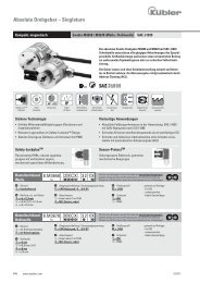
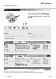
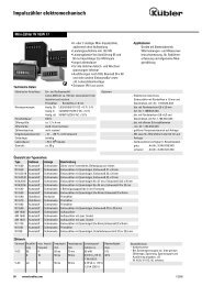
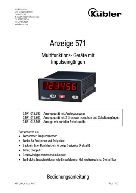
Anzeige 571<br />
Multifunktions- Geräte mit<br />
Impulseingängen<br />
0.571.012.E90: Anzeigegerät mit Analogausgang<br />
0.571.011.E00: Anzeigegerät mit 2 Grenzwertvorgaben <strong>und</strong> Schaltausgängen<br />
0.571.012.E05: Anzeige mit serieller Schnittstelle<br />
Betriebsarten als<br />
� Tachometer, Frequenzmesser<br />
� <strong>Zähl</strong>er für Positionen <strong>und</strong> Ereignisse<br />
� Backzeit- bzw. Durchlaufzeit- Anzeige (reziproke Drehzahl)<br />
� Timer, Stoppuhr<br />
� Geschwindigkeitsmesser aus Laufzeit<br />
� Zahlreiche Zusatzfunktionen wie Linearisierung, Helligkeitsregelung, Digitalfilter<br />
Bedienungsanleitung
0.571_09c_d.doc / Jun-12 Page 2 / 32<br />
Sicherheitshinweise<br />
� Diese Beschreibung ist wesentlicher Bestandteil des Gerätes <strong>und</strong> enthält wichtige<br />
Hinweise bezüglich Installation, Funktion <strong>und</strong> Bedienung.<br />
Nichtbeachtung kann zur Beschädigung oder zur Beeinträchtigung der Sicherheit<br />
von Menschen <strong>und</strong> Anlagen führen!<br />
� Das Gerät darf nur von einer Elektrofachkraft eingebaut, angeschlossen <strong>und</strong> in<br />
Betrieb genommen werden<br />
� Es müssen alle allgemeinen sowie länderspezifischen <strong>und</strong> anwendungsspezifischen<br />
Sicherheitsbestimmungen beachtet werden<br />
� Wird das Gerät in Prozessen eingesetzt, bei denen ein eventuelles Versagen oder<br />
eine Fehlbedienung die Beschädigung der Anlage oder eine Verletzung des<br />
Bedienungspersonals zur Folge haben kann, dann müssen entsprechende<br />
Vorkehrungen zur sicheren Vermeidung solcher Folgen getroffen werden<br />
� Bezüglich Einbausituation, Verdrahtung, Umgebungsbedingungen, Abschirmung <strong>und</strong><br />
Erdung von Zuleitung gelten die allgemeinen Standards für den Schaltschrankbau in<br />
der Maschinenindustrie<br />
� - Irrtümer <strong>und</strong> Änderungen vorbehalten -<br />
Version: Beschreibung:<br />
01/wb/sb/April 02 Original Version<br />
02/wb/sb/July 03 Ergänzungen für serielles Interface<br />
03/wb/sb/Jan. 04 Ergänzung der seriellen Codes<br />
04/wb/sb/Dez. 04 - <strong>Zähl</strong>ermode: Bereicheserweiterung<br />
Setwert/Vorwahl 1/ Vorwahl 2/Anabeg/Anaend:<br />
–199 999 … +999 999;<br />
- Bürde Stromausgang 270 Ohm<br />
- Parameter Wait bei RPM / Time: Eingabe „0“ ist nicht möglich.<br />
05/wb/sb/Jan.07 - Broschüre A5, Ausführung mit 3 Tasten<br />
08c/wb/sb/Feb.08 - Korrekturen: Scrollen negativer Werte <strong>und</strong> Auto-Reset/Set<br />
08d/wb/sb/Jan.09 - Korrektur Kommastelle bei analogem Hub<br />
08e/wb/Nov.11 Kapitel 5 um Updatezeiten Analogausgang ergänzt<br />
09c/wb/Mai12 Funktionserweiterung: Linearisierung, Printer Mode
0.571_09c_d.doc / Jun-12 Page 3 / 32<br />
Inhaltsverzeichnis<br />
1. Elektrische Anschlüsse ..................................................................................... 4<br />
1.1. Stromversorgung ...................................................................................................5<br />
1.2. Hilfsspannungsausgang ........................................................................................5<br />
1.3. Eingänge A, B <strong>und</strong> Reset.......................................................................................5<br />
1.4. Skalierbarer Analogausgang (nur 0.571.012.E90).................................................6<br />
1.5. Optokoppler- Transistor- Ausgänge (nur 0.571.011.E00) ......................................6<br />
1.6. Serielle RS232 / RS485-Schnittstelle (nur 0.571.012.E05) ...................................7<br />
2. Funktion der Programmiertasten ....................................................................... 8<br />
3. Gr<strong>und</strong>einstellungen .......................................................................................... 9<br />
4. Einstellung der Betriebsparameter...................................................................10<br />
4.1. RPM, Betrieb als Tachometer <strong>und</strong> Frequenzzähler .............................................10<br />
4.2. Time, Betrieb als Backzeit- <strong>und</strong> Durchlaufzeit- Anzeige (reziproke Drehzahl) ..11<br />
4.3. Timer, Betrieb als Stoppuhr ................................................................................12<br />
4.4. Count, Betriebsart als <strong>Zähl</strong>er ..............................................................................13<br />
4.5. Speed, Geschwindigkeitsanzeige aus Laufzeitmessung.....................................14<br />
4.6. Linearisierungspunkte .........................................................................................14<br />
5. Zusätzliche Parameter bei Geräten mit Analogausgang (0.571.012.E90) .........15<br />
6. Zusätzliche Parameter bei Geräten mit Grenzwertvorgaben (0.571.011.E00) ...17<br />
7. Zusätzliche Parameter bei Geräten mit serieller Schnittstelle<br />
(0.571.012.E05) ...............................................................................................19<br />
7.1. Printer-Mode .......................................................................................................21<br />
8. Sonderfunktionen ............................................................................................22<br />
8.1. Linearisierung (nur in Betriebsart RPM <strong>und</strong> Count).............................................22<br />
8.2. Manuelle Eingabe oder „Teachen“ der Linearisierungspunkte ..........................24<br />
9. Setzen aller Parameter auf Default-Werte.......................................................26<br />
10. Maßbilder........................................................................................................26<br />
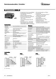
11. Technische Daten ............................................................................................27<br />
12. Parameter-Liste ...............................................................................................28
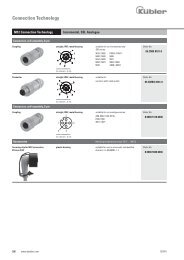
1. Elektrische Anschlüsse<br />
0.571.012.E90: Anzeigegerät mit Analogausgang<br />
0.571_09c_d.doc / Jun-12 Page 4 / 32<br />
1 2 3 4 5 6 7 8 9 10<br />
GND<br />
17-30VCD IN<br />
INPUT A<br />
INPUT B<br />
RESET (C)<br />
GND<br />
+24VDC OUT<br />
GND ANALOG<br />
+/- 10V ANALOG<br />
0/4-20mA ANALOG<br />
0.571.011.E00: Anzeigegerät mit 2 Grenzwertvorgaben<br />
1 2 3 4 5 6 7 8 9 10<br />
GND<br />
17-30VCD IN<br />
INPUT A<br />
INPUT B<br />
RESET (C)<br />
GND<br />
+24VDC OUT<br />
COM+<br />
OUT 1<br />
OUT 2<br />
0.571.012.E05: Anzeigegerät mit serieller Schnittstelle<br />
1 2 3 4 5 6 7 8 9 10<br />
GND<br />
17-30VCD IN<br />
INPUT A<br />
INPUT B<br />
RESET (C)<br />
GND<br />
+24VDC OUT<br />
GND<br />
RXD / A (+)<br />
TXD / B (-)<br />
PE GND<br />
230VAC<br />
115 VAC<br />
0 VAC<br />
PE GND<br />
230VAC<br />
115 VAC<br />
0 VAC<br />
GND<br />
230VAC<br />
PE<br />
115 VAC<br />
0 VAC
1.1. Stromversorgung<br />
Über die Klemmen 1 <strong>und</strong> 2 kann das Gerät mit einer Gleichspannung zwischen 17 <strong>und</strong> 30 VDC<br />
versorgt werden. Die Stromaufnahme hängt von der Höhe der Versorgungsspannung ab <strong>und</strong><br />
liegt typisch zwischen 80mA <strong>und</strong> 150mA (zuzüglich des am Hilfsspannungsausgang<br />
entnommenen Geberstromes).<br />
Die Klemmen 0 VAC, 115 VAC <strong>und</strong> 230 VAC erlauben die Geräteversorgung direkt vom Netz.<br />
Die Anschlussleistung beträgt 7,5 VA.<br />
Der gestrichelt eingezeichnete Erdungsanschluss ist intern mit Gerätemasse verb<strong>und</strong>en <strong>und</strong> ist<br />
sicherheitstechnisch oder EMV- technisch nicht notwendig. Bei manchen Anwendungen kann<br />
es jedoch wünschenswert sein, das Bezugspotential für die Signale zu erden.<br />
Bitte bei Erdung von GND beachten:<br />
� Es sind damit alle digitalen <strong>und</strong> analogen Bezugspotentiale geerdet<br />
� Doppelerdung bei DC- Versorgung ist unbedingt zu vermeiden, wenn z.B. der<br />
Minuspol der Versorgungsspannung schon extern geerdet ist.<br />
1.2. Hilfsspannungsausgang<br />
An Klemme 7 steht, unabhängig von der Art der Geräteversorgung, eine Hilfsspannung von 24<br />
VDC/ max. 150 mA zur Versorgung von Gebern <strong>und</strong> Sensoren zur Verfügung.<br />
1.3. Eingänge A, B <strong>und</strong> Reset<br />
Die Eingänge können im Gr<strong>und</strong>- Setup für PNP- Betrieb (gegen + schaltend) oder für NPN-<br />
Betrieb (gegen – schaltend) definiert werden. Die Definition bezieht sich auf alle 3 Eingänge<br />
gleichzeitig. Die Default- Einstellung ist PNP.<br />
� Unabhängig von der getroffenen Definition sind alle Funktionen „active<br />
HIGH“ <strong>und</strong> das Gerät wertet die positiven Flanken aus. Da bei NPN-<br />
Einstellung ein offener RESET- Eingang auf HIGH liegt, muss dieser daher<br />
stets extern auf GND- Potential gelegt werden, damit das Gerät arbeitsfähig<br />
ist. Andernfalls bleibt das Gerät permanent im Reset- Zustand.<br />
� Bei Verwendung von 2-Draht NAMUR- Sensoren muss NPN angewählt<br />
werden. Der negative Pol des Sensors wird mit GND <strong>und</strong> der positive Pol mit<br />
dem entsprechenden Eingang verb<strong>und</strong>en.<br />
0.571_09c_d.doc / Jun-12 Page 5 / 32
Typische Eingangsschaltung:<br />
Input<br />
4,7k<br />
PNP<br />
GND GND<br />
0.571_09c_d.doc / Jun-12 Page 6 / 32<br />
+24V int.<br />
Input<br />
+24V int.<br />
4,7k<br />
NPN<br />
Die <strong>Zähl</strong>eingänge A <strong>und</strong> B verarbeiten Frequenzen bis zu 25 kHz. (Betriebsart <strong>Zähl</strong>er bis 100<br />
kHz). Die Minimum- Impulsdauer am Reset- Eingang ist 500 µsec.<br />
Die Impulseingänge des Gerätes sind für eine Grenzfrequenz von 100 kHz <strong>und</strong> somit für<br />
elektronische Impulsgeber ausgelegt. Sollten Sie ausnahmsweise mechanische Kontakte als<br />
Impulsquelle benutzen, muss an den Anschlussklemmen zwischen GND(-) <strong>und</strong> dem<br />
entsprechenden Eingang (+) ein handelsüblicher, externer Kondensator angebracht werden. Bei<br />
einer Kapazität von 10µF wird die maximale Eingangsfrequenz auf 20 Hz bedämpft <strong>und</strong> damit<br />
die Prellung des mechanischen Schalters unterdrückt.<br />
1.4. Skalierbarer Analogausgang (nur 0.571.012.E90)<br />
Es steht ein Spannungsausgang von 0 - +10V bzw. von –10V....+10V sowie ein separater<br />
Stromausgang 0/4 – 20 mA proportional zum Messwert zur Verfügung. Beide Ausgänge<br />
beziehen sich auf GND- Potential. Die Polarität des Ausgangssignals richtet sich nach dem<br />
angezeigten Vorzeichen. Die Auflösung beträgt 14 Bit. Die Reaktionszeit auf Änderungen des<br />
Messwertes ist abhängig von der Betriebsart. Details sind in Kapitel 5 beschrieben.<br />
Der Spannungsausgang ist mit 2 mA belastbar, die Bürde am Stromausgang darf zwischen Null<br />
<strong>und</strong> 270 Ohm liegen.<br />
1.5. Optokoppler- Transistor- Ausgänge (nur 0.571.011.E00)<br />
Das Schaltverhalten dieser potentialfreien Ausgänge ist programmierbar. Klemme 8 (COM+)<br />
muss mit dem positiven Pol der zu schaltenden Spannung verb<strong>und</strong>en werden. Der zulässige<br />
Spannungsbereich ist 5 – 30 Volt <strong>und</strong> der zulässige Maximalstrom 150 mA pro Ausgang. Beim<br />
Schalten induktiver Lasten wird eine zusätzliche, externe Bedämpfung der Spule durch eine<br />
Diode empfohlen.<br />
Vorwahl2 Opto Vorwahl1<br />
Opto 33 R<br />
33 R<br />
(8)<br />
(9)<br />
(10)<br />
GND<br />
Com+ (5 ... 35 V)<br />
Ausgang 1 (max. 150 mA)<br />
Ausgang 2 (max. 150 mA)
1.6. Serielle RS232 / RS485-Schnittstelle (nur 0.571.012.E05)<br />
Ab Werk ist die serielle Schnittstelle auf RS232 konfiguriert. Eine Umstellung auf RS485<br />
(2-Leiter) ist an einem internen DIL-Schalter möglich. Hierzu müssen die Schraubklemmleisten<br />
abgesteckt <strong>und</strong> die Rückwand des Gerätes abgenommen werden. Danach kann die Platine nach<br />
hinten aus dem Gehäuse herausgezogen werden.<br />
0.571_09c_d.doc / Jun-12 Page 7 / 32<br />
DIL-Switch<br />
ON DIP<br />
Abnehmen der Rückwand Lage des DIL-Schalters<br />
ON<br />
RS232:<br />
10<br />
9<br />
8<br />
TxD<br />
RxD<br />
GND<br />
ON<br />
RS485:<br />
10<br />
9<br />
8<br />
B (-)<br />
A (+)<br />
GND<br />
Achtung!<br />
� Niemals am DIL-Schalter die Schieber 1 <strong>und</strong> 2 oder die Schieber 3 <strong>und</strong> 4<br />
gleichzeitig auf ON stellen!<br />
� Nach Einstellung des Schalters Platine bitte vorsichtig in das Gehäuse<br />
zurückschieben, damit die Übergabestifte zur frontseitigen Tastatur nicht<br />
beschädigt werden.
2. Funktion der Programmiertasten<br />
Das Gerät wird über 2 frontseitige Tasten bedient.<br />
Die linke Taste (ENTER) rollt die einzelnen Menüpunkte durch.<br />
Mit der mittleren Taste (SET) wird ein entsprechender Menüpunkt angewählt <strong>und</strong> die<br />
gewünschte Auswahl getroffen bzw. der zugehörige Zahlenwert verändert.<br />
Wiederum mit der ENTER-Taste wird die Auswahl oder der Wert bestätigt <strong>und</strong> zum nächsten<br />
Menüpunkt weitergeschaltet.<br />
Die rechte Taste wird für das „Teachen“ der Linearisierungspunkte (siehe Abschnitt 8.2)<br />
benötigt.<br />
Zum Einstieg in die Programmierung muss ENTER für ca. 3 sec. betätigt werden.<br />
Bei numerischen Eingaben blinkt zunächst die kleinste Dekade. Durch Dauerbetätigung der SET-<br />
Taste kann der Zahlenwert der blinkenden Ziffer verändert werden (r<strong>und</strong> laufender<br />
Scroll- Durchgang 0, 1, 2, ......9, 0, 1, 2 usw.). Bei Loslassen der SET- Taste bleibt der<br />
letzte Wert stehen <strong>und</strong> die nächst höhere Ziffer blinkt. So können der Reihe nach alle Dekaden<br />
auf den gewünschten Wert eingestellt werden. Nach Einstellung der höchsten Dekade blinkt<br />
wieder die kleinste Dekade, so dass bei Bedarf noch Korrekturen durchgeführt werden können.<br />
Bei vorzeichenbehafteten Parametern scrollt die höchste Dekade zunächst von 0 bis 9 (positive<br />
Werte), gefolgt von den negativen Werten „ -1“ <strong>und</strong> „-“.<br />
Zur Speicherung des angezeigten Zahlenwertes wird die ENTER- Taste betätigt, womit<br />
das Gerät gleichzeitig auf den nächsten Menüpunkt weiterschaltet.<br />
Das Gerät schaltet von der Programmier-Routine in den normalen Arbeitsbetrieb zurück, wenn<br />
die Taste (ENTER) mindestens 3 Sek<strong>und</strong>en lang betätigt wird.<br />
Eine „time-out“- Funktion sorgt dafür, dass nach einer Betätigungspause von jeweils 10<br />
Sek<strong>und</strong>en das Gerät automatisch eine Menüebene höher bzw. zurück in den Betriebszustand<br />
springt. Alle Eingaben, die zu diesem Zeitpunkt noch nicht mit ENTER bestätigt wurden,<br />
bleiben unberücksichtigt.<br />
Während der Programmierung sind alle <strong>Zähl</strong>funktionen des Gerätes gesperrt!<br />
0.571_09c_d.doc / Jun-12 Page 8 / 32
3. Gr<strong>und</strong>einstellungen<br />
Die nachfolgend beschriebenen Einstellungen sind in der Regel einmaliger Art <strong>und</strong> sind nur bei<br />
der erstmaligen Inbetriebnahme notwendig.<br />
Zur besseren Übersicht wird in Abschnitt 3 <strong>und</strong> Abschnitt 4 die Parametrierung der reinen<br />
Anzeige beschrieben, wohingegen zusätzliche Einstellmöglichkeiten für Ausführungen mit<br />
Analogausgang, Grenzwertüberwachung oder serieller Schnittstelle später erklärt werden.<br />
Das Gr<strong>und</strong>menü beinhaltet die Auswahl der Gerätefunktion, die Eingangsdefinition PNP/ NPN<br />
sowie die gewünschte Helligkeit der Digitalanzeige.<br />
Das Gr<strong>und</strong>einstell-Menü wird aktiviert, wenn für mindestens 3 Sek<strong>und</strong>en<br />
beide frontseitigen Tasten <strong>und</strong> gleichzeitig betätigt werden<br />
Menü Auswahl Text Beschreibung<br />
Type Messfunktion des Gerätes<br />
0.571_09c_d.doc / Jun-12 Page 9 / 32<br />
RPM Tachometer/ Frequenzmesser (4.1)<br />
Time Durchlaufzeit/Backzeit-Anzeige (4.2)<br />
Timer Stoppuhr (4.3)<br />
Count Positionszähler, Ereigniszähler (4.4)<br />
Speed Geschwindigkeitsanzeige aus Laufzeit (4.5)<br />
Char Charakteristik der Impulseingänge<br />
NPN gegen –schaltend<br />
PNP gegen +schaltend<br />
Bright Helligkeit Anzeige 20%, 40%, 60% 80% <strong>und</strong> 100%<br />
Code Zugriffssperre für die Tastatur<br />
No Tastatur immer frei geschaltet<br />
ALL Tastatur für alle Funktionen gesperrt<br />
P_FrEE Tastatur gesperrt mit Ausnahme der Vorwahlwerte<br />
Pres 1 <strong>und</strong> Pres 2 (nur 0.571.011.E00)<br />
LrnodE Linearisierungsmode, nur verfügbar in Betriebsart<br />
RPM <strong>und</strong> Count (näheres siehe Abschnitt 8)<br />
No Die Linearisierung ist ausgeschaltet.<br />
1-9UA Die Linearisierung wird nur im positiven<br />
Wertebereich durchgeführt. Bei negativen Werten<br />
wird die Kurve am Nullpunkt gespiegelt.<br />
4-9UA Linearisierung im gesamten Bereich.
4. Einstellung der Betriebsparameter<br />
Wenn die vorgenannten Gr<strong>und</strong>einstellungen getroffen sind, kann durch Betätigung der ENTER-<br />
Taste das Parametermenü aufgerufen werden (mindestens 3 Sek<strong>und</strong>en). Es erscheinen nur<br />
diejenigen Parameter, die für die gewählte Anwendung relevant sind. Der Ausstieg aus dem<br />
Parameter- Menü erfolgt durch eine Betätigung der ENTER-Taste länger als 3 Sek<strong>und</strong>en, oder<br />
automatisch über Time-out.<br />
Wenn die Code- Sperre für die Tastatur eingeschaltet wurde, erscheint bei Tastaturbetätigung<br />
zunächst die Anzeige<br />
Die Tastatur wird frei geschaltet, wenn innerhalb von 10 Sek<strong>und</strong>en die Tastenfolge<br />
eingegeben wird. Ansonsten kehrt das Gerät automatisch zur normalen Anzeige zurück<br />
4.1. RPM, Betrieb als Tachometer <strong>und</strong> Frequenzzähler<br />
(Input A = aktiver Eingang, Input B = unbenutzt; Ausnahme siehe Kapitel 5)<br />
Menü Auswahl Text Beschreibung<br />
Frequenz Stellen Sie hier einen für ihre Anwendung<br />
typischen Frequenzwert im Bereich von<br />
1Hz bis 25 000 Hz ein.<br />
Display Stellen Sie hier den Zahlenwert ein, den Sie bei<br />
0.571_09c_d.doc / Jun-12 Page 10 / 32<br />
Decimal<br />
point<br />
obiger Frequenz auf der Anzeige sehen möchten.<br />
Wählen Sie die gewünschte Stellung des Dezimal-<br />
Punktes entsprechend den im Display<br />
erscheinenden Formaten.<br />
Wait Wie lange soll das Gerät bei Ausbleiben der<br />
Eingangsimpulse warten, bis die Anzeige auf 0000<br />
geht? Geben Sie hier die gewünschte Wartezeit in<br />
Sek<strong>und</strong>en ein. Bei Eingabe “0“ bleibt der letzte<br />
Anzeigewert ohne Nullstellung solange<br />
eingefroren, bis aus neu eingegangenen Impulsen<br />
ein neuer Messwert berechnet wurde.<br />
Filter Zuschaltbare Mittelwertsbildung zur Vermeidung<br />
von Anzeigeschwankungen bei unstabilen<br />
Eingangsfrequenzen.<br />
OFF Keine Mittelswertbildung<br />
2, 4, 8, 16 = Zahl der fließenden<br />
Mittelwertszyklen.
Bei Geräten der Ausführung 0.571.012.E90 kann die Drehzahl auch mit einem drehrichtungsabhängigen<br />
Vorzeichen angezeigt werden.<br />
Hierzu siehe 5.<br />
4.2. Time, Betrieb als Backzeit- <strong>und</strong> Durchlaufzeit- Anzeige<br />
(reziproke Drehzahl)<br />
(Input A = Frequenzeingang, Input B = unbenutzt)<br />
Menü Auswahl Text Beschreibung<br />
0.571_09c_d.doc / Jun-12 Page 11 / 32<br />
Display-<br />
Format:<br />
Wählen Sie zwischen vollen Sek<strong>und</strong>en, vollen<br />
Minuten, Minuten <strong>und</strong> Sek<strong>und</strong>en (9999:59) oder<br />
Minuten mit zwei dezimalen Kommastellen.<br />
Der Dezimalpunkt stellt sich durch die Formatwahl<br />
automatisch ein.<br />
Frequenz Stellen Sie hier einen für ihre Anwendung<br />
typischen Frequenzwert im Bereich von 1 Hz bis<br />
25 000 Hz ein.<br />
Display Stellen Sie hier den Zahlenwert ein, den Sie bei<br />
obiger Frequenz auf der Anzeige sehen möchten.<br />
Wait Wie lange soll das Gerät bei Ausbleiben der<br />
Eingangsimpulse warten, bis die Anzeige auf 0000<br />
geht? Geben Sie hier die gewünschte Wartezeit in<br />
Sek<strong>und</strong>en ein. Bei Eingabe “0“ bleibt der letzte<br />
Anzeigewert ohne Nullstellung solange<br />
eingefroren, bis aus neu eingegangenen Impulsen<br />
ein neuer Messwert berechnet wurde.<br />
Filter Zuschaltbare Mittelwertsbildung zur Vermeidung<br />
von Anzeigeschwankungen bei unstabilen<br />
Eingangsfrequenzen<br />
OFF: Keine Mittelswertbildung.<br />
2, 4, 8, 16 = Zahl der fließenden<br />
Mittelwertszyklen.
4.3. Timer, Betrieb als Stoppuhr<br />
Bitte beachten Sie bei dieser Betriebsart, dass offene NPN- Eingänge gr<strong>und</strong>sätzlich „HIGH“ <strong>und</strong><br />
offene PNP- Eingänge gr<strong>und</strong>sätzlich „LOW“ sind!<br />
Menü Auswahl Text Beschreibung<br />
Base Wählen Sie die zur Messung gewünschte<br />
Zeitbasis bzw. Auflösung:<br />
Millisek<strong>und</strong>en<br />
0.571_09c_d.doc / Jun-12 Page 12 / 32<br />
1/100 Sek<strong>und</strong>en<br />
1/10 Sek<strong>und</strong>en<br />
volle Sek<strong>und</strong>en<br />
Minuten mit 2 Dezimalstellen<br />
Minuten mit einer Dezimalstelle<br />
St<strong>und</strong>en : Minuten : Sek<strong>und</strong>en<br />
Start High_Low: Zeitzählung läuft, solange Input A<br />
„HIGH“ ist<br />
Start_Stop Ansteigende Flanke an Input A startet<br />
Zeitmessung, ansteigende Flanke an Input B<br />
stoppt Zeitmessung<br />
A_StSP Periodendauer-Messung. Zeigt zyklisch die<br />
Zeitdauer zwischen zwei ansteigenden Flanken an<br />
Input A an.<br />
Reset: NO Zeitzählung arbeitet addierend, kein<br />
automatisches Reset bei nächstem Start.<br />
Nulleinstellung muss über Reset- Eingang<br />
erfolgen.<br />
YES Mit jedem Start beginnt die neue Zeitzählung<br />
automatisch bei Null.<br />
Latch: NO Der Zeitablauf ist in der Anzeige sichtbar.<br />
YES Die Anzeige speichert das Endergebnis der letzten<br />
Zeitmessung, während die neue Messung im<br />
Hintergr<strong>und</strong> abläuft.
4.4. Count, Betriebsart als <strong>Zähl</strong>er<br />
Menü Auswahl Text Beschreibung<br />
0.571_09c_d.doc / Jun-12 Page 13 / 32<br />
Mode:<br />
A_Bdir<br />
Eingang A ist der <strong>Zähl</strong>eingang. Eingang B<br />
bestimmt die <strong>Zähl</strong>richtung: LOW = vorwärts HIGH<br />
= rückwärts<br />
A u B Summe, zählt Impulse A + Impulse an B<br />
A - B Differenz, zählt Impulse an A – Impulse an B<br />
A_B.1 Vor/Rückwärtszähler für Impulse mit 2x90°<br />
Versatz, einfache Flankenauswertung (x1)<br />
A_B.2 Vor/Rückwärtszähler für Impulse mit 2x90°<br />
Versatz, doppelte Flankenauswertung (x2)<br />
A_B.4 Vor/Rückwärtszähler für Impulse mit 2x90°<br />
Versatz, vierfache Flankenauswertung (x4)<br />
Factor Impulsbewertungsfaktor 0,0001 – 9,9999. Bei<br />
Einstellung von z.B. 1,2345 zeigt das Gerät nach<br />
10 000 Eingangsimpulsen den Wert 12 345.<br />
Set Setzwert –199 999...0...999 999.<br />
Bei einem Reset-Befehl wird der <strong>Zähl</strong>er auf den<br />
hier eingestellten Gr<strong>und</strong>wert gesetzt.<br />
Reset Definiert die Art des Reset-Befehls<br />
N0 Kein Setzen/ Rücksetzen möglich<br />
Front Setzen/Rücksetzen über frontseitige SET-Taste.<br />
Extern Setzen über Reset-Eingang.<br />
Fr u E Setzen/Rücksetzen über frontseitige SET-Taste<br />
<strong>und</strong> über Reset- Eingang.<br />
Dpoint Setzt den Dezimalpunkt auf die im Display<br />
gezeigte Stelle.<br />
Hinweis:<br />
Der <strong>Zähl</strong>er kann nur Werte zwischen -199999 <strong>und</strong> 999999 darstellen.<br />
Liegen die Werte außerhalb dieses Bereiches, so wird angezeigt.
4.5. Speed, Geschwindigkeitsanzeige aus Laufzeitmessung<br />
Bei dieser Betriebsart dient Eingang A als Starteingang <strong>und</strong> Eingang B als Stoppeingang für<br />
eine Laufzeitmessung. Das Gerät ermittelt daraus die Geschwindigkeit eines passierenden<br />
Objekts.<br />
Menü Auswahl Text Beschreibung<br />
Time Geben Sie hier eine typische Laufzeit ein.<br />
Einstellbereich 000.001 bis 999.999 Sek<strong>und</strong>en.<br />
Displ Geben Sie hier ein, welche Geschwindigkeit das<br />
Gerät bei obiger Referenzzeit anzeigen soll<br />
Dpoint Setzt den Dezimalpunkt auf die im Display<br />
gezeigte Stelle.<br />
Wait Wie lange soll das Gerät nach einer Messung<br />
warten, bis die Anzeige auf 0000 geht? Geben Sie<br />
hier die gewünschte Wartezeit in Sek<strong>und</strong>en ein.<br />
Bei Eingabe “0“ bleibt der letzte Anzeigewert ohne<br />
Nullstellung solange eingefroren, bis aus neu<br />
eingegangenen Impulsen eine neue<br />
Geschwindigkeit berechnet wurde<br />
4.6. Linearisierungspunkte<br />
Die Linearisierungspunkte werden nur in den Betriebsarten RMP <strong>und</strong> Count bei eingeschalteter<br />
Linearisierung angezeigt.<br />
Menü Auswahl Text Beschreibung<br />
P01_X X-Koordinate des 1. Linearisierungspunktes.<br />
Einstellbereich -199999 bis 999999.<br />
P01_Y Y-Koordinate des 1. Linearisierungspunktes.<br />
Einstellbereich -199999 bis 999999.<br />
: :<br />
: :<br />
P16_X X-Koordinate des 16. Linearisierungspunktes.<br />
Einstellbereich -199999 bis 999999.<br />
P16_Y Y-Koordinate des 16. Linearisierungspunktes.<br />
Einstellbereich -199999 bis 999999.<br />
Einzelheiten zur Linearisierung siehe Abschnitt 8.<br />
0.571_09c_d.doc / Jun-12 Page 14 / 32
5. Zusätzliche Parameter bei Geräten mit<br />
Analogausgang (0.571.012.E90)<br />
Hier erscheinen bereits im Gr<strong>und</strong>einstellmenü die folgenden, zusätzlichen Basis- Parameter:<br />
Menü Auswahl Text Beschreibung<br />
A-Char Ausgangs-Charakteristik. Wählen Sie zwischen<br />
+/- 10Volt (bipolar), 0-10V (nur positiv), 0-20mA<br />
oder 4-20mA.<br />
0.571_09c_d.doc / Jun-12 Page 15 / 32<br />
Offset Stellen Sie den Wert auf 0, wenn ihr<br />
Analogausgang bei Null (bzw. 4mA) beginnen soll.<br />
Wenn Sie einen anderen Nullpunkt wünschen, ist<br />
dieser hier einzugeben (Eingabe von z.B. 5.000<br />
bedeutet, dass der Analogausgang im Nullzustand<br />
bereits 5 Volt Ausgangsspannung liefert).<br />
Gain Stellen Sie hier den gewünschten Hub ein. Eine<br />
Einstellung von 10.00 entspricht einem Bereich<br />
von 10 Volt bzw. 20 mA, eine Einstellung von z.B.<br />
2.00 reduziert den Hub auf 2 Volt bzw. 4 mA.<br />
Wenn das bipolare Ausgangsformat (+/- 10Volt) angewählt wird, muss an den Impulseingängen<br />
A <strong>und</strong> B ein zweispuriges Signal mit Phasenversatz anliegen. Die Polarität des Ausgangs folgt<br />
dem Vorzeichen in der Anzeige. (Betrieb als <strong>Zähl</strong>er oder als Drehzahl- Anzeige mit<br />
Drehrichtungserkennung)<br />
Die folgenden Betriebsparameter dienen zur Skalierung des Analogausgangs:<br />
Menü Auswahl Text Beschreibung<br />
Anabeg Über die zusätzlich im normalen Einstellmenü<br />
Anaend<br />
erscheinenden Parameter Anabeg (Analog-Beginn)<br />
<strong>und</strong> Anaend (Analog- Ende) können Sie einen<br />
Ausschnitt des gesamten Messbereiches auf den<br />
gewählten Analogbereich abbilden. Wenn Sie z.B.<br />
Anabeg auf -1500 <strong>und</strong> Anaend auf 2100 einstellen,<br />
erzeugt der Analogausgang bei Anzeige -1500 den<br />
zuvor definierten Anfangswert <strong>und</strong> bei Anzeige<br />
2100 den zuvor definierten Endwert.
Reaktionszeiten des Analogausgangs:<br />
Betriebsart Updatezeit Analogausgang<br />
Tachometer/ Frequenzmesser (4.1.) 330ms bei f >3Hz<br />
1/f bei f < 3Hz<br />
Durchlaufzeit/ Backzeit-Anzeige (4.2.) 330ms bei f >3Hz<br />
1/f bei f < 3Hz<br />
Stoppuhr (4.3.) 7 ms<br />
(In der Latch-Funktion nach Ende jeder<br />
Messung)<br />
Positionszähler, Ereigniszähler (4.4.) <strong>Zähl</strong>ereignis + 7ms<br />
Geschwindigkeitsanzeige aus Laufzeit (4.5.) Laufzeit + 7ms<br />
Der Analogausgang verhält sich gleich wie die Anzeige.<br />
0.571_09c_d.doc / Jun-12 Page 16 / 32
6. Zusätzliche Parameter bei Geräten mit<br />
Grenzwertvorgaben (0.571.011.E00)<br />
Im Gr<strong>und</strong>einstell-Menü erscheinen zusätzlich die folgenden Parameter. Soweit Wischimpulse<br />
programmiert werden, beträgt die Impulszeit des Ausganges jeweils 300 msec (Fixwert, nur<br />
werksseitig veränderbar).<br />
Mit den Einstellungen „Char1“ <strong>und</strong> „Char2“ kann die Schaltcharakteristik für Ausgang 1 bzw.<br />
Ausgang 2 entsprechend der untenstehenden Tabelle vorgegeben werden.<br />
Mit den Parametern „Hyst1“ <strong>und</strong> „Hyst2“ kann jedem der beiden Ausgänge zusätzlich noch eine<br />
Schalt-Hysterese zugeordnet werden.<br />
Die Schalt-Hysterese ist nur wirksam in den Betriebsarten RPM (Tachometer) <strong>und</strong><br />
Time (Backzeit-Anzeige).<br />
Die Arbeitsrichtung der Hysterese hängt von der gewählten Schaltcharakteristik “GE” oder “LE”<br />
ab, wie im untenstehenden Bild verdeutlicht.<br />
ON<br />
OFF<br />
GE = Greater/Equal LE= Lower/Equal<br />
Menü Auswahl Text Beschreibung<br />
GE Greater/Equal. Ausgang wird statisch aktiv, wenn<br />
Anzeigewert größer oder gleich Vorwahlwert ist.<br />
LE Lower/Equal. Ausgang wird statisch aktiv, wenn<br />
Anzeigewert kleiner oder gleich Vorwahlwert ist<br />
GE Greater/Equal. Ausgang wird dynamisch aktiv,<br />
wenn Anzeigewert den Vorwahlwert überschreitet<br />
(Wischimpuls).<br />
LE Lower/Equal. Ausgang wird dynamisch aktiv,<br />
wenn Anzeigewert den Vorwahlwert<br />
unterschreitet (Wischimpuls).<br />
0.571_09c_d.doc / Jun-12 Page 17 / 32<br />
Hyst<br />
Vorwahlwert<br />
Preset<br />
Hinweis"Anlaufüberbrückung":<br />
Hinweis zur Anlauf-Überbrückung:<br />
Wenn SiePreset1inder Betriebsart RPM oderTIME<br />
zur Wenn Überwachung Sie Vorwahl eines Minimum-Wertes 1 mit Einstellung benutzen LE<br />
(Charakteristik benutzen, LE), umdannarbeitet den Minimum-Wert Ausgang1 mit einer zu<br />
automatischenAnlaufüberbrückung überwachen, dann führt das <strong>und</strong>wirderst Gerät dann<br />
aktiv, bei wennnachNeueinschaltungder den Betriebsarten RPMVorwahlwert <strong>und</strong> TIME<br />
erstmals automatisch überschritten eine wurde. Anlaufüberbrückung<br />
Hint "Start-up-delay":<br />
When aus. you Nach use Preset1 Netzzuschaltung for monitoring a minimum wird der value<br />
(LE Minimum-Kontakt characteristics) with operation erst dann modesaktiviert, RPM or TIME,<br />
then wenn output1 derwill Messwert provide an automatic den Vorwahlwert<br />
start-up delay and<br />
switch on only after the measuring value has overpassed<br />
das erste mal überschritten hatte.<br />
the preset for the first time after power up.
Menü Auswahl Text Beschreibung<br />
Res **) Wischimpuls <strong>und</strong> automatisches Reset auf Null<br />
bei Erreichen/Überschreiten von Vorwahlwert 1.<br />
Set **) Wischimpuls <strong>und</strong> automatisches Setzen auf<br />
Vorwahl 1 bei Erreichen/Unterschreiten von Null.<br />
Wie Char 1<br />
0.571_09c_d.doc / Jun-12 Page 18 / 32<br />
Wie Char 1<br />
Wie Char 1<br />
Wie Char 1<br />
Ausgang schaltet statisch, wenn der Messwert<br />
den Wert von Vorwahl 1 – Vorwahl 2 erreicht*)<br />
Ausgang schaltet dynamisch, wenn der Messwert<br />
den Wert von Vorwahl 1 – Vorwahl 2 erreicht*)<br />
*) Dient zur Erzeugung eines „Vorsignals“ in festem Abstand von einem Hauptsignal (z.B.<br />
Kriechgang-Stopp), indem der Schaltpunkt von Ausgang 2 jeder Verstellung von Vorwahl 1<br />
automatisch folgt (Schleppvorwahl).<br />
**) Diese Einstellungen begrenzen die <strong>Zähl</strong>frequenz auf 1 kHz.<br />
Menü Auswahl Text Beschreibung<br />
Pres_1 Die Vorwahlwerte selbst werden jeweils am<br />
Pres_2<br />
Anfang des normalen Bedienmenüs abgefragt<br />
bzw. vorgegeben.<br />
Anzeige des Schaltzustandes der Ausgänge<br />
1_2off Im Betrieb kann der Zustand der beiden<br />
1_2on<br />
1 on<br />
2on<br />
Schaltausgänge jederzeit abgefragt werden.<br />
Hierzu wird nur kurz die ENTER-Taste angetippt.<br />
Das Display zeigt dann für ca. 2sec. eine der<br />
nebenstehenden Informationen.
7. Zusätzliche Parameter bei Geräten mit<br />
serieller Schnittstelle (0.571.012.E05)<br />
Im Gr<strong>und</strong>einstellung- Menü werden die Gr<strong>und</strong>parameter der Schnittstelle definiert. Dazu<br />
gehören die Baudrate, das Datenformat <strong>und</strong> die serielle Geräteadresse. Die<br />
Werkseinstellungen sind jeweils in Klammern angegeben.<br />
Menü Auswahl Text Beschreibung<br />
S-Unit Serielle Geräte-Adresse (11):<br />
Den Geräten können Adressen zwischen 11 <strong>und</strong> 99<br />
zugeordnet werden.<br />
Werkseinstellung = 11.<br />
Adressen die eine “0“ enthalten sind nicht erlaubt,<br />
da diese als Gruppen- bzw. Sammeladressen<br />
verwendet werden.<br />
Serielles Datenformat (7 E 1):<br />
Das erste Zeichen gibt die Anzahl der Datenbits<br />
an, das zweite Zeichen steht für Parity<br />
„Even“,“Odd“ oder kein Parity-Bit. Das dritte<br />
Zeichen gibt die Anzahl der Stopp-Bits an.<br />
0.571_09c_d.doc / Jun-12 Page 19 / 32<br />
Baudrate (9600):<br />
Es können die nebenstehenden Baudraten gewählt<br />
werden:
Menü Auswahl Text Beschreibung<br />
S-tim Serieller Timer (0.100):<br />
Wenn die Schnittstelle mit dem nachfolgenden<br />
Parameter auf „Print1“ oder „Print2“ eingestellt<br />
wird, sendet das Gerät zyklisch alle x,xxx<br />
Sek<strong>und</strong>en einen String, der aus den folgenden<br />
ASCII-Zeichen besteht: siehe Kapitel 7.1<br />
Menü Auswahl Text Beschreibung<br />
PC Kommunikation gemäß dem Drivecom-Protokoll<br />
nach ISO 1745*<br />
0.571_09c_d.doc / Jun-12 Page 20 / 32<br />
Print1 siehe oben. Detaillierung siehe Kapitel 7.1<br />
Print2 siehe oben. Detaillierung siehe Kapitel 7.1<br />
S-Code Serieller Register-Code.<br />
Spezifiziert die Codestelle des Parameters, dessen<br />
Daten ausgelesen werden sollen. Der Register-<br />
Code für den vom Gerät angezeigten, aktuellen<br />
Messwert ist 101 <strong>und</strong> wird beim PC-Protokoll mit<br />
den ASCII-Zeichen „:“ <strong>und</strong> „1“ dargestellt.<br />
* Das Protokoll benutzt zur Anfrage eines Wertes den nachfolgend beschriebenen Request-<br />
String (Beispiel: Anfrage bei Unit-Nummer 11 nach dem Inhalt des Registers mit dem<br />
Code 101 = Aktueller Messwert)<br />
EOT ... AD1 AD2 C1 C2 ENQ<br />
(04) (31) (31) (3A) (31) (05)<br />
(EOT) (1) (1) (:) (1) (ENQ)<br />
Hex-Code<br />
ASCII-Code<br />
0000 0100 0011 0001 0011 0001 0011 1010 0011 0001 0000 0101 Binary<br />
EOT: Control character<br />
AD1: Unit address, high byte<br />
AD2: Unit address, low byte<br />
C1: Register code, high byte<br />
C2: Register code, low byte<br />
ENQ: Control character<br />
Wenn die zu übertragenden Messdaten xxxx im Beispiel den Zahlenwert „-180“ haben, lautet<br />
die Antwort des Gerätes:<br />
STX C1 C2 x x x x ETX BCC<br />
(02) (3A) (31) (2D) (31) (38) (30) (03) (1C) Hex-Code<br />
(STX) (:) (1) (-) (1) (8) (0) (ETX)<br />
0000 0010 0011 1010 0011 0001 0010 1101 0011 0001 0011 1000 0011 0000 0000 0011 0001 1100<br />
ASCII-Code<br />
Binary<br />
Vornullen werden nicht übertragen.<br />
BCC ist ein „Block-Check-Charakter“, der sich durch ein Exklusiv-Oder aller Zeichen zwischen<br />
einschließlich C1 <strong>und</strong> ETX ergibt.
Bei fehlerhaftem Anfragestring antwortet das Gerät nur mit STX C1 C2 EOT oder mit NAK.<br />
Geräte mit serieller Schnittstelle verfügen auch über einen seriellen Set/Reset-Befehl<br />
(identisch zur Funktion der frontseitigen Reset-Taste oder eines externen Reset-Signals)<br />
Um Reset zu aktivieren, muss die Zahl “1” in die Code-Stelle “60” geschrieben werden. Das<br />
Schreiben von “0” hebt den Reset-Zustand wieder auf.<br />
Die untenstehende Zeichenfolge erklärt, wie der serielle Set/Reset-Befehl bei einem Gerät mit<br />
der seriellen Adresse 11 funktioniert:<br />
Reset ON :<br />
Reset OFF :<br />
EOT... AD1 AD2 STX C1 C2 Dat ETX BCC<br />
(04) (31) (31) (02) (36) (30) (31) (03) (34)<br />
(EOT) (1) (1) (STX) (6) (0) (1) ETX (4)<br />
0000 0100 0011 0001 0011 0001 0000 0010 0011 0110 0011 0000 0011 0001 0000 0 011 0011 0100<br />
EOT... AD1 AD2 STX C1 C2 Dat ETX BCC<br />
(04) (31) (31) (02) (36) (30) (30) (03) (35)<br />
(EOT) (1) (1) (STX) (6) (0) (0) ETX (5)<br />
0000 0100 0011 0001 0011 0001 0000 0010 0011 0110 0011 0000 0011 0000 0000 0 011 0011 0101<br />
7.1. Printer-Mode<br />
Der Printer-Mode ermöglicht die zyklische oder manuelle Auslösung der Übertragung eines<br />
Registerwertes. Das Register wird mittels des Parameters „S-Code“ spezifiziert.<br />
Parameter „S-mod“ erlaubt die Auswahl zwischen zwei verschiedenen Sendestrings.<br />
„S-mod“ Sendestring<br />
„Print1“ Leerzeichen Vorzeichen Daten Line Carriage<br />
feed return<br />
+/- X X X X X X LF CR<br />
„Print2“ Vorzeichen Daten Carriage<br />
return<br />
+/- X X X X X X CR<br />
0.571_09c_d.doc / Jun-12 Page 21 / 32<br />
HEX<br />
ASCII<br />
BIN<br />
HEX<br />
ASCII<br />
BIN
Die Art der Auslösung wird wie folgt angewählt:<br />
Zyklische Auslösung Seriellen Timer auf einen Wert ≥ 0,010 sec. einstellen.<br />
Mit "S-mod" den Sendestring auswählen.<br />
Nach dem Verlassen des Einstellmenüs wird das zyklische Versenden<br />
automatisch gestartet.<br />
Manuelle Auslösung Seriellen Timer auf Null einstellen.<br />
Mit "S-mod" den Sendestring auswählen.<br />
8. Sonderfunktionen<br />
0.571_09c_d.doc / Jun-12 Page 22 / 32<br />
Nach dem Verlassen des Einstellmenüs kann eine Übertragung durch<br />
kurze Betätigung der Enter-Taste ausgelöst werden.<br />
8.1. Linearisierung (nur in Betriebsart RPM <strong>und</strong> Count)<br />
Mit Hilfe dieser Funktion kann auf einfache Weise ein lineares Eingangssignal in eine<br />
nichtlineare Darstellung umgewandelt werden (oder umgekehrt). Es stehen 16 Linearisierungs-<br />
Punkte zur Verfügung, die über den gesamten Wandlungsbereich in beliebigen Abständen<br />
verteilt werden können. Zwischen 2 vorgegebenen Koordinaten findet automatisch eine lineare<br />
Interpolation statt.<br />
Es empfiehlt sich, an Stellen mit starker Kurvenkrümmung möglichst viele Punkte zu setzen,<br />
wohingegen an Stellen mit schwacher Krümmung nur wenige Punkte ausreichend sind. Um<br />
eine Linearisierungskurve vorzugeben, muss der Parameter „Linearisierungsmode“ auf 1-quA<br />
oder auf 4-quA eingestellt werden (siehe nachstehendes Schaubild).<br />
Mit den Parametern P01_X bis P16_X geben Sie 16 x- Koordinaten vor. Das sind die normalen<br />
Anzeigewerte, die das Gerät ohne Linearisierung in Abhängigkeit des Eingangssignals erzeugt.<br />
Mit den Parametern P01_Y bis P16_Y geben Sie nun vor, welchen Wert die Anzeige an dieser<br />
Stelle stattdessen annehmen soll.<br />
Es wird also zum Beispiel der Wert P02_x wird durch den Wert P02_y ersetzt.<br />
� Aus Konsistenzgründen müssen die x- Register mit kontinuierlich<br />
ansteigenden Werten belegt werden, d.h. es muss die Bedingung<br />
P01_X < P02_X < … < P15_X < P16_X erfüllt sein.<br />
� Unabhängig vom Linearisierungsmode ist der vom Gerät akzeptierte Eingabebereich für die<br />
Punkte P01_X, P01_Y,…, P16_X, P16_Y immer -199999 … 999999.<br />
� Bei Messwerten kleiner als P01_X zeigt das Gerät konstant P01_Y an.<br />
� Bei Messwerten größer als P16_X zeigt das Gerät konstant P16_Y an.
*)<br />
y<br />
0.571_09c_d.doc / Jun-12 Page 23 / 32<br />
P16(x)= 1000<br />
P16(y)= 800<br />
x<br />
P1(x)= 0<br />
P1(y)= 0<br />
Linearisation Mode = 1_quA<br />
P1(x)= -1000<br />
P1(y)= 900<br />
*) Kurve verläuft punktsymmetrisch zum 1. Quadranten<br />
P8(x)= 0<br />
P8(y)= 750<br />
y<br />
x<br />
P16(x)= +1000<br />
P16(y)= - 600<br />
Linearisation Mode = 4_quA<br />
Anwendungsbeispiel:<br />
Das untenstehende Bild zeigt eine Wasserschleuse, bei der die Öffnungsweite über einen<br />
inkrementalen Drehgeber erfasst <strong>und</strong> zur Anzeige gebracht werden soll. Der Geber erzeugt in<br />
dieser Anordnung ein Signal proportional zum Drehwinkel φ, gewünscht ist jedoch die direkte<br />
Anzeige der Öffnungsweite "d"<br />
d<br />
Anzeigewert<br />
d = d0 (1-cos φ)<br />
φ<br />
Drehgeber
P16_y<br />
P15_y<br />
P07_y<br />
P05_y<br />
P03_y<br />
P01_y<br />
P01_x<br />
Anzeigewert<br />
P03_x<br />
0.571_09c_d.doc / Jun-12 Page 24 / 32<br />
P05_x<br />
P07_x<br />
P15_x<br />
P16_x<br />
Geberposition<br />
8.2. Manuelle Eingabe oder „Teachen“ der Linearisierungspunkte<br />
Die Punkte zur Bildung einer Linearisierungskurve können wie alle Parameter mit dem normalen<br />
Tastatur-Dialog vorgegeben werden. In diesem Falle werden alle Werte P01_x bis P16_x <strong>und</strong><br />
die zugeordneten Ersatzwerte P01_y bis P16_y einzeln eingegeben.<br />
Der Benutzer muss bei manueller Eingabe die Konsistenz der Werte P01_x bis P16_x<br />
gewährleisten ( P01_X < P02_X < … < P15_X < P16_X )<br />
Eine Überwachung durch das Gerät erfolgt nicht.<br />
In den meisten Fällen ist es aber praktischer, die eingebaute „Teach“-Funktion zu benutzen.<br />
Hierbei bewegt man den Geber schrittweise auf die gewünschten Stützpunkte <strong>und</strong> gibt per<br />
Tastatur den jeweils dazugehörigen Anzeigewert vor.<br />
So benutzen Sie die eingebaute Teach-Funktion zur Vorgabe einer Linearisierungskurve:<br />
� Bitte wählen Sie unter den Basis-Parametern den gewünschten Linearisierungsmode<br />
aus (siehe auch Abschnitt 3).<br />
� Halten Sie die Taste „Cmd“ für 3 Sek<strong>und</strong>en gedrückt. Auf dem Display erscheint<br />
die Anzeige „tEACh“. Um den Teach-Vorgang zu beginnen, drücken Sie bitte innerhalb<br />
der nächsten 10 Sek<strong>und</strong>en nochmals kurz die Taste „Cmd“.<br />
Auf der Anzeige erscheint nun „P01_X“.
� Aus Konsistenzgründen werden automatisch alle Linearisierungspunkte zunächst mit<br />
Startwerten überschrieben. Die Startwerte sind für „P01_X“ <strong>und</strong> „P01_Y“ gleich<br />
-199999. Alle anderen Stützpunkte haben den Startwert 999999.<br />
� Betätigen Sie nochmals „Cmd“ , um den momentan vom Geber gelieferten Istwert<br />
anzuzeigen. Sorgen Sie nun dafür, dass die Position des SSI-Gebers dem ersten<br />
Linearisierungs-Stützpunkt entspricht.<br />
� Sobald Sie in der Anzeige den X-Wert des ersten Linearisierungspunktes sehen, drücken<br />
Sie erneut die „Cmd“-Taste. Der momentane Anzeigewert wird als „P01_X“<br />
abgespeichert <strong>und</strong> für ca. 1 Sek<strong>und</strong>e zeigt das Display „P01_Y“. Danach wird wieder der<br />
gespeicherte P01_X-Wert angezeigt.<br />
� Diesen X-Wert können Sie nun wie bei einer normalen Parameter-Eingabe beliebig<br />
verändern, um daraus den gewünschten Y-Wert zu bilden.<br />
� Nachdem der gewünschte P01_Y-Wert eingestellt ist, wird dieser durch erneute<br />
Betätigung von „Cmd“ gespeichert, <strong>und</strong> das Gerät schaltet auf den nächsten Stützpunkt<br />
P02_x weiter.<br />
� Wenn Sie den letzten Punkt P16_x programmiert haben, beginnt die Routine erneut<br />
beim ersten Stützpunkt P01_X. Sie haben damit Gelegenheit, die Eingaben nochmals zu<br />
kontrollieren <strong>und</strong> bei Bedarf nochmals zu korrigieren.<br />
� Beenden Sie den Teach-Vorgang, indem Sie für 2 Sek<strong>und</strong>en die Taste „ENTER“ drücken.<br />
Das Display zeigt dann für 2 Sek<strong>und</strong>en „StoP“ <strong>und</strong> kehrt zur normalen Anzeige-Betrieb<br />
zurück. Die Linearisierungs-Stützpunkte sind nun gespeichert.<br />
� Das Gerät überwacht die Konsistenzbedingung. Die x-Koordinate des neuen Stützpunktes<br />
muss größer als der vorherige Wert sein. Sollte dieses nicht zutreffen, dann leuchten am<br />
unteren Rand des Displays 6 Punkte als Warnsignal auf. Eine Übernahme des inkorrekten<br />
Stützpunktes mittels Cmd-Taste ist nicht möglich. Bei der Betätigung der Cmd-Taste wird<br />
stattdessen der Fehlertext "E.r.r.-.L.O." ausgegeben.<br />
� Sie haben jederzeit die Möglichkeit, den Teach-Vorgang auf eine der folgenden beiden<br />
Arten abzubrechen:<br />
0.571_09c_d.doc / Jun-12 Page 25 / 32<br />
1. Drücken Sie für 2 Sek<strong>und</strong>en die Enter-Taste. Auf dem Display erscheint für etwa 1 sec<br />
„Stop“. Danach schaltet das Gerät in den Normalbetrieb zurück.<br />
2. Tun Sie einfach gar nichts. Nach etwa 10 Sek<strong>und</strong>en schaltet das Gerät automatisch in<br />
den Normalbetrieb zurück.<br />
In beiden Fällen werden die Linearisierungsparameter P01_x bis P16_y nicht geändert.
9. Setzen aller Parameter auf Default-Werte<br />
Sie können jederzeit bei Bedarf sämtliche Parameter des Gerätes auf die ursprünglich<br />
werksseitig eingestellten Default- Werte zurücksetzen. Um dies zu tun:<br />
� Schalten Sie die Stromversorgung des Gerätes aus<br />
� drücken Sie ENTER-Taste<br />
� schalten Sie die Stromversorgung bei gedrückte ENTER-Taste wieder ein.<br />
10. Maßbilder<br />
Diese Aktion setzt alle Parameter auf die Werkseinstellungen zurück <strong>und</strong> alle<br />
getroffenen Einstellungen gehen verloren.<br />
Das Gerät muss also wieder vollständig neu eingestellt werden.<br />
Die Default-Werte sind aus den nachfolgenden Tabellen ersichtlich..<br />
110,0 (4.331’’)<br />
96,0 (3.780’’)<br />
48,0 (1.890)<br />
Schalttafelausschnitt: 91,0 x 44,0 mm<br />
0.571_09c_d.doc / Jun-12 Page 26 / 32<br />
44,0 (1.732)<br />
8,0<br />
(.315)<br />
10,0<br />
(.394)<br />
9,0 (.345) 129,0 (5.079)<br />
140,5 (5.531)<br />
91,0 (3.583)
11. Technische Daten<br />
Nennspannung AC : 115/230 V (+/- 12,5 %)<br />
Anschlussleistung : 7,5 VA<br />
Nennspannung DC : 24V (17 – 30V)<br />
Stromaufnahme (ohne Geber) : 18V : 120mA, 24V : 95 mA, 30V : 80mA<br />
Hilfsspannung für Impulsgeber : 24V DC, +/- 15%, 150mA (bei AC- <strong>und</strong> DC-Versorgung)<br />
Eingänge : 3 (PNP/NPN/Namur), A/B = Impulse, C = Reset<br />
Stromaufnahme Eingänge : 5,1 mA / 24V (Ri = 4,7 kOhm)<br />
Eingangspegel HTL : Low: 0...3,5V, High: 9...30V<br />
Max. Eingangsfrequenz : 100 kHz bei Betriebsart als <strong>Zähl</strong>er (Count)<br />
25 kHz bei allen anderen Betriebsarten<br />
Eingang C: 1kHz (Mindest-Impulsdauer 500 µsec.)<br />
Genauigkeit Frequenzmessung : +/- 1 ppm +/- 1 Digit<br />
Aktiver Analogausgang : Strom: 0/4...20mA (Bürde max. 270 Ohm)<br />
(0.571.012.E90) Spannung: 0...+/- 10V (Belastung max. 2 mA)<br />
Auflösung analog : 14 Bit + Vorzeichen<br />
Genauigkeit analog : 0,1%<br />
Reaktionszeit analog : Abhängig von der Betriebsart. Details, siehe Kapitel 5<br />
Umgebungstemperatur : 0° - 45° (Betrieb), -25° - +70° (Lagerung)<br />
Gehäuse : Norly UL94 – V-0<br />
Anzeige : 6 Digit, LED, high- efficiency orange, 15mm<br />
Schutzart : Frontseitig IP65, rückseitig IP20<br />
Schalttafel-Ausschnitt : 91 x 44mm<br />
Anschlussklemmen : Signale max. 1.5 mm², AC-Versorgung max. 2.5 mm²<br />
Schaltausgänge (0.571.011.E00) : PNP, max. 30 V, max. 150 mA<br />
Konformität <strong>und</strong> Normen : EMV 2004/108/EG: EN 61000-6-2<br />
EN 61000-6-3<br />
NS 2006/95/EG: EN 61010-1<br />
0.571_09c_d.doc / Jun-12 Page 27 / 32
12. Parameter-Liste<br />
Bezeichnung Text<br />
Min -<br />
Wert<br />
Max -<br />
Wert<br />
Wert<br />
fett = default<br />
Stellen Zeichen<br />
Ser.<br />
Code<br />
Auswahl<br />
Betriebsmode tYPE 0 4<br />
Gr<strong>und</strong>einstellungen<br />
0 1 0 00 rpm<br />
1 time<br />
2 timer<br />
3 count<br />
4 speed<br />
NPN / PNP CHAr 0 1 0 1 0 01 npn<br />
1 pnp<br />
Helligkeit briGht 0 4 0 1 0 02 100<br />
1 80<br />
2 60<br />
3 40<br />
4 20<br />
Tastatursperre Code 0 2 0 1 0 03 no<br />
1 all<br />
2 Preset free<br />
RPM, Betrieb als Tachometer<br />
Frequenz FrEqu 1 25000 1000 5 0 04<br />
Anzeige bei Freq. diSPL 1 99999 1000 5 0 05<br />
Dezimalpunkt dPoint 0 5 3 1 0 06 0.000<br />
Rückstellzeit WAit 0,1 99,9 1,0 3 1 07<br />
Mittelwert FiLtEr 0 4 0 1 0 08 off<br />
1 2<br />
2 4<br />
3 8<br />
4 16<br />
Time, Betrieb als Durchlaufzeit / Backzeit-Anzeige<br />
Anzeigeformat diSFor 0 3 0 1 0 09 sec<br />
1 min<br />
2 min-sec<br />
3 min-h<br />
Frequenz FrEqu 1 25000 100 5 0 10<br />
Anzeige bei Freq. diSPL 1 999999 100 6 0 11<br />
Rückstellzeit WAit 0,1 99,9 5,0 3 1 12<br />
Mittelwert FiLtEr 0 4 0 1 0 13 off<br />
1 2<br />
2 4<br />
3 8<br />
4 16<br />
0.571_09c_d.doc / Jun-12 Page 28 / 32
Bezeichnung Text<br />
Min -<br />
Wert<br />
Max -<br />
Wert<br />
Wert<br />
fett = default<br />
Stellen Zeichen<br />
Ser.<br />
Code<br />
Auswahl<br />
Timer, Betrieb als Stoppuhr<br />
Auflösung bASE 0 6 0 1 0 14 sec - 000<br />
1 sec - 00<br />
2 sec - 0<br />
3 sec<br />
4 min - 00<br />
5 min - 0<br />
6 hr.min.s<br />
Start / Stop StArt 0 2 0 1 0 15 hi - lo<br />
1 st – sp<br />
2 ast - sp<br />
Auto-Reset rESEt 0 1 0 1 0 16 no<br />
1 yes<br />
Speicheranzeige LAtcH 0 1 0 1 0 17 no<br />
1 yes<br />
Count, Betrieb als <strong>Zähl</strong>er<br />
<strong>Zähl</strong>er-Mode modE 0 5 0 1 0 18 A-B div<br />
1 A+B<br />
2 A-B<br />
3 A_B-1<br />
4 A_B-2<br />
5 A_B-4<br />
Faktor FActor 0,0001 9,9999 1,0000 5 4 19<br />
Setzwert SEt -199999 +999999 0 +/- 6 0 20<br />
Reset / Set rESEt 0 3 0 1 0 21 no<br />
1 Front<br />
2 E_tErn<br />
3 FruE<br />
Dezimalpunkt dPoint 0 5 0 1 0 22<br />
Speed, Geschwindigkeitsmessung aus Laufzeit<br />
Messzeit timE 1 999999 1000 6 0 23<br />
Anzeigewert bei<br />
Messzeit.<br />
diSPL 1 999999 1000 6 0 24<br />
Dezimalpunkt dPoint 0 5 0 1 0 25<br />
Rückstellzeit WAit 0,0 99,9 10,0 3 1 26<br />
0.571_09c_d.doc / Jun-12 Page 29 / 32
Bezeichnung Text<br />
Min -<br />
Wert<br />
Max -<br />
Wert<br />
Wert<br />
fett = default<br />
Linearisierung<br />
Stellen Zeichen<br />
Ser.<br />
Code<br />
Auswahl<br />
Linearisierungsmode<br />
LrnodE 0 2 0 1 0 D2<br />
P1(x) P01_H -199999 999999 999999 +/- 6 0 A0<br />
P1(y) P01_Y -199999 999999 999999 +/- 6 0 A1<br />
P2(x) P02_H -199999 999999 999999 +/- 6 0 A2<br />
P2(y) P02_Y -199999 999999 999999 +/- 6 0 A3<br />
P3(x) P03_H -199999 999999 999999 +/- 6 0 A4<br />
P3(y) P03_Y -199999 999999 999999 +/- 6 0 A5<br />
P4(x) P04_H -199999 999999 999999 +/- 6 0 A6<br />
P4(y) P04_Y -199999 999999 999999 +/- 6 0 A7<br />
P5(x) P05_H -199999 999999 999999 +/- 6 0 A8<br />
P5(y) P05_Y -199999 999999 999999 +/- 6 0 A9<br />
P6(x) P06_H -199999 999999 999999 +/- 6 0 B0<br />
P6(y) P06_Y -199999 999999 999999 +/- 6 0 B1<br />
P7(x) P07_H -199999 999999 999999 +/- 6 0 B2<br />
P7(y) P07_Y -199999 999999 999999 +/- 6 0 B3<br />
P8(x) P08_H -199999 999999 999999 +/- 6 0 B4<br />
P8(y) P08_Y -199999 999999 999999 +/- 6 0 B5<br />
P9(x) P09_H -199999 999999 999999 +/- 6 0 B6<br />
P9(y) P09_Y -199999 999999 999999 +/- 6 0 B7<br />
P10(x) P10_H -199999 999999 999999 +/- 6 0 B8<br />
P10(y) P10_Y -199999 999999 999999 +/- 6 0 B9<br />
P11(x) P11_H -199999 999999 999999 +/- 6 0 C0<br />
P11(y) P11_Y -199999 999999 999999 +/- 6 0 C1<br />
P12(x) P12_H -199999 999999 999999 +/- 6 0 C2<br />
P12(y) P12_Y -199999 999999 999999 +/- 6 0 C3<br />
P13(x) P13_H -199999 999999 999999 +/- 6 0 C4<br />
P13(y) P13_Y -199999 999999 999999 +/- 6 0 C5<br />
P14(x) P14_H -199999 999999 999999 +/- 6 0 C6<br />
P14(y) P14_Y -199999 999999 999999 +/- 6 0 C7<br />
P15(x) P15_H -199999 999999 999999 +/- 6 0 C8<br />
P15(y) P15_Y -199999 999999 999999 +/- 6 0 C9<br />
P16(x) P16_H -199999 999999 999999 +/- 6 0 D0<br />
P16(y) P16_Y -199999 999999 999999 +/- 6 0 D1<br />
Die Linearisierungspunkte werden nur in den Betriebsarten RMP <strong>und</strong> Count bei eingeschalteter<br />
Linearisierung angezeigt.<br />
0.571_09c_d.doc / Jun-12 Page 30 / 32
Bezeichnung Text<br />
Min -<br />
Wert<br />
Max -<br />
Wert<br />
Wert<br />
fett = default<br />
Stellen Zeichen<br />
Ser.<br />
Code<br />
Auswahl<br />
Grenzwertvorgaben (0.571.011.E00)<br />
Vorwahl 1 PrES 1 -199999 +999999 10000 +/- 6 0 27<br />
Vorwahl 2 PrES 2 -199999 +999999 5000 +/- 6 0 28<br />
Vorwahlmode 1 CHAr 1 0 0 0 1 0 29 � GE<br />
1 � LE<br />
2 �� GE<br />
3 �� LE<br />
4 �� RES<br />
5 �� SET<br />
Vorwahlmode 2 CHAr 2 0 5 0 1 0 30 � GE<br />
1 � LE<br />
2 �� GE<br />
3 �� LE<br />
4 � 1-2<br />
5 �� 1-2<br />
Schalthysterese 1 HYSt1 0 99999 0 5 0 31<br />
Schalthysterese 2 HYSt2 0 99999 0 5 0 32<br />
Analogausgang (0.571.012.E90)<br />
Analog Anfang An-bEG" -199999 999999 0 +/-6 0 33<br />
Analog Endwert An-End -199999 999999 10000 +/-6 0 34<br />
Analog Mode A-CHAr 0 3 0 1 0 35 �10 V<br />
1 0 ... 10V<br />
2 0 ... 20 mA<br />
3 4 ... 20 mA<br />
Offset OFFSEt -9,999 9,999 0,000 +/- 4 3 36<br />
Gain GAin 00,00 99,99 10,00 4 2 37<br />
0.571_09c_d.doc / Jun-12 Page 31 / 32
Bezeichnung Text<br />
Min -<br />
Wert<br />
Max -<br />
Wert<br />
Wert<br />
fett = default<br />
Stellen Zeichen<br />
Ser.<br />
Code<br />
Auswahl<br />
Serielle Schnittstelle (0.571.012.E05)<br />
Serielles Formal S-Form 0 9 0 1 0 92 0 = 7E1<br />
1 1 = 7E2<br />
2 2 = 701<br />
3 3 = 702<br />
4 4 = 7N01<br />
5 5 = 7N02<br />
6 6 = 8E1<br />
7 7 = 801<br />
8 8 = 8N01<br />
9 9 = 8N02<br />
Baudrate S-bAUd 0 6 0 1 0 91 0 = 9600<br />
1 1 = 4850<br />
2 2 = 2400<br />
3 3 = 1200<br />
4 4 = 600<br />
5 5 = 19200<br />
6 6 = 38400<br />
Geräte-Adresse S-Unit 0 99 11 2 0 90 �<br />
Serieller Timer S-tim 10 9999 100 4 3 38 �<br />
Serieller Mode S-mod 0 1 0 1 0 39 0 = PC<br />
1 1 = print<br />
Codestelle für<br />
Print-Funktion<br />
S-CodE 100 120 101 3 0 40 �<br />
0.571_09c_d.doc / Jun-12 Page 32 / 32
<strong>Fritz</strong> <strong>Kübler</strong> <strong>GmbH</strong><br />
<strong>Zähl</strong>- <strong>und</strong> <strong>Sensortechnik</strong><br />
Postfach 34 40<br />
D-78023 Villingen-Schwenningen<br />
Tel.: 07720-3903-0<br />
Fax: 07720-21564<br />
www.kuebler.com<br />
0.571_09c_e.doc / Jun-12 Page 1 / 32<br />
Display 571<br />
Universal Display Units with<br />
Impulse Inputs<br />
0.571.012.E90: Display with analogue output<br />
0.571.011.E00: Display with two presets and outputs<br />
0.571.012.E05: Display with serial interface<br />
Operation modes:<br />
� Tachometer, frequency meter<br />
� Counter for positions and events<br />
� Baking time, processing time (reciprocal speed)<br />
� Timer, stopwatch<br />
� Speed display from delay between a Start and a Stop input<br />
� Additional Functions: Linearization, Brightness Control, Digital Filter etc.<br />
Operating <strong>Instructions</strong>
0.571_09c_e.doc / Jun-12 Page 2 / 32<br />
Safety <strong>Instructions</strong><br />
� This manual is an essential part of the unit and contains important hints about<br />
function, correct handling and commissioning. Non-observance can result in<br />
damage to the unit or the machine or even in injury to persons using the<br />
equipment!<br />
� The unit must only be installed, connected and activated by a qualified electrician<br />
� It is a must to observe all general and also all country-specific and applicationspecific<br />
safety standards<br />
� When this unit is used with applications where failure or maloperation could cause<br />
damage to a machine or hazard to the operating staff, it is indispensable to meet<br />
effective precautions in order to avoid such consequences<br />
� Regarding installation, wiring, environmental conditions, screening of cables and<br />
earthing, you must follow the general standards of industrial automation industry<br />
� - Errors and omissions excepted –<br />
Version: Description<br />
01/wb/sb/April 02<br />
02/wb/sb/July 03 Supplements for 571 serial interface<br />
03/wb/sb/Jan. 04 Range extensions and supplements for serial code<br />
04/wb/sb/Jan. 07 Version with 3 keys, A5 brochure<br />
08c/wb/sb/Feb.08 Corrections: Scrolling to negative values, Auto-Reset/Set<br />
08d/wb/sb/Jan.09 Correction: Decimal point with Parameter "Gain"<br />
08e/wb/Dec.11 Chapter 5 supplemented by “Response time of analogue output”<br />
09c/wb/May 12 Extended functions: Linearization, Printer Mode
0.571_09c_e.doc / Jun-12 Page 3 / 32<br />
Table of Contents<br />
1. Electrical Connections................................................................................. 4<br />
1.1. Power supply .........................................................................................................5<br />
1.2. Aux. voltage output ...............................................................................................5<br />
1.3. Inputs A, B and Reset............................................................................................5<br />
1.4. Adjustable analogue output (0.571.012.E90 only) ................................................6<br />
1.5. Optocoupler (transistor) outputs (0.571.011.E00 only)..........................................6<br />
1.6. Serial RS232 / RS485 interface (0.571.012.E05 only)...........................................7<br />
2. How to Operate the Keys ............................................................................ 8<br />
3. Basic Settings............................................................................................. 9<br />
4. Operational registers ................................................................................ 10<br />
4.1. RPM, operation as tachometer or frequency counter .........................................10<br />
4.2. Time, display of baking or processing time (reciprocal speed)...........................11<br />
4.3. Timer, stopwatch.................................................................................................12<br />
4.4. Count, Counter mode...........................................................................................13<br />
4.5. Speed from differential time between a Start and a Stop input ........................14<br />
4.6. Linearization points .............................................................................................14<br />
5. Additional Settings for Units with Analogue Output (0.571.012.E90)........ 15<br />
6. Additional settings for Units with Presets (0.571.011.E00)........................ 17<br />
7. Additional settings for Units with serial interface (0.571.012.E05) ............ 19<br />
7.1. Printer-Mode .......................................................................................................21<br />
8. Special Functions...................................................................................... 22<br />
8.1. Linearization ........................................................................................................22<br />
8.2. Manual Input or „Teaching“ of the Interpolation Points.....................................24<br />
9. Set all register to “Default“ ...................................................................... 26<br />
10. Dimensions............................................................................................... 26<br />
11. Technical Data.......................................................................................... 27<br />
12. Parameter List........................................................................................... 28
1. Electrical Connections<br />
0.571.012.E90: Display with analogue output<br />
0.571_09c_e.doc / Jun-12 Page 4 / 32<br />
1 2 3 4 5 6 7 8 9 10<br />
GND<br />
17-30VCD IN<br />
INPUT A<br />
INPUT B<br />
RESET (C)<br />
GND<br />
+24VDC OUT<br />
GND ANALOG<br />
+/- 10V ANALOG<br />
0/4-20mA ANALOG<br />
0.571.011.E00: Display with two presets and outputs<br />
1 2 3 4 5 6 7 8 9 10<br />
GND<br />
17-30VCD IN<br />
INPUT A<br />
INPUT B<br />
RESET (C)<br />
GND<br />
+24VDC OUT<br />
COM+<br />
OUT 1<br />
OUT 2<br />
0.571.012.E05: Display with serial interface<br />
1 2 3 4 5 6 7 8 9 10<br />
GND<br />
17-30VCD IN<br />
INPUT A<br />
INPUT B<br />
RESET (C)<br />
GND<br />
+24VDC OUT<br />
GND<br />
RXD / A (+)<br />
TXD / B (-)<br />
PE GND<br />
230VAC<br />
115 VAC<br />
0 VAC<br />
PE GND<br />
230VAC<br />
115 VAC<br />
0 VAC<br />
GND<br />
230VAC<br />
PE<br />
115 VAC<br />
0 VAC
1.1. Power supply<br />
The unit accepts DC supply from 17V to 30V when using terminals 1 and 2, and the<br />
consumption depends on the level of the supply voltage (typical 80mA at 30V or 150mA at 17V,<br />
plus current taken from aux. output).<br />
For AC supply, terminals 0 VAC, 115 VAC or 230 VAC can be used. The total AC power<br />
consumption is 7.5 VA.<br />
The diagrams show a dotted line for gro<strong>und</strong>ing to PE. This connection is not really necessary,<br />
neither for safety nor for EMC. However, for some applications, it can be useful to gro<strong>und</strong> the<br />
common potential of all signal lines.<br />
When using this earthing option, please observe:<br />
� All terminals and potentials marked “GND“ will be earthed.<br />
� Please avoid multiple earthing, e.g. when you use a DC power supply<br />
where the Minus is already connected to earth etc.<br />
1.2. Aux. voltage output<br />
Terminal 7 provides an auxiliary output of 24VDC/150mA max. for supply of sensors and<br />
encoders.<br />
1.3. Inputs A, B and Reset<br />
In the basic setup menu, these inputs can be configured to PNP (signal must switch to +) or<br />
to NPN (signal must switch to -). This configuration is valid for all three inputs at a time. The<br />
factory setting is always PNP.<br />
Please note:<br />
� Independent of your setting, all functions of the unit are “active HIGH“<br />
and the unit triggers to positive transitions (rising edge). Because, with<br />
NPN setting, open or unused inputs are HIGH, you must tie the Reset line<br />
to GND for operation. Otherwise, your unit will be in a continuous RESET<br />
state and cannot work.<br />
� Where your use 2-wire NAMUR type sensors, please select NPN, connect<br />
the negative wire of the sensor to GND and the positive wire to the<br />
corresponding input.<br />
0.571_09c_e.doc / Jun-12 Page 5 / 32
Typical input circuit:<br />
Input<br />
4,7k<br />
0.571_09c_e.doc / Jun-12 Page 6 / 32<br />
PNP<br />
+24V int.<br />
GND GND<br />
Input<br />
+24V int.<br />
Counting inputs A and B are designed for input frequencies up to 100 KHz with all counter<br />
modes, and up to 25 kHz with all other operating modes.<br />
The minimum pulse duration on the Reset input must be 500 µsec.<br />
All inputs are designed to receive impulses from an electronic impulse source. Where<br />
exceptionally you need to use mechanical contacts, please connect an external capacitor<br />
between GND (-) and the corresponding input (+). With a capacity of 10 µF, the maximum input<br />
frequency will reduce to 20 Hz and miscounting due to contact bouncing will be eliminated.<br />
4,7k<br />
NPN<br />
GND<br />
1.4. Adjustable analogue output (0.571.012.E90 only)<br />
A voltage output is available, operating in a range of 0...+10V or –10V....+10V according to<br />
setting. At the same time, a current output 0/4 – 20mA is available. Both outputs refer to the<br />
GND potential and the polarity changes with the sign in the display. The outputs provide a<br />
14 bits resolution and the response time to changes of the measuring value value depends on<br />
mode of operation. For details please see chapter 5.<br />
The maximum current of the voltage output is 2 mA, and the load on the current output can vary<br />
between 0 and max. 270 Ohms.<br />
1.5. Optocoupler (transistor) outputs (0.571.011.E00 only)<br />
The outputs provide programmable switching characteristics and are potential-free. Please<br />
connect terminal 8 (COM+) to the positive potential of the voltage you like to switch (range<br />
5V....35V). You must not exceed the maximum output current of 150mA. Where you switch<br />
inductive loads, please provide filtering of the coil by means of an external diode.<br />
Preset 2 Opto Preset 1<br />
Opto 33 R<br />
33 R<br />
(8)<br />
(9)<br />
(10)<br />
Com+ (5 ... 35 V)<br />
Output 1 (max. 150 mA)<br />
Output 2 (max. 150 mA)
1.6. Serial RS232 / RS485 interface (0.571.012.E05 only)<br />
Ex factory the unit is set to RS232 communication. This setting can be changed to RS485<br />
(2-wire) by means of an internal DIL switch. To access the DIL switch, you must remove the<br />
screw terminal connectors and the backplane. Then pull the print to the rear to remove the PCB<br />
from the housing.<br />
0.571_09c_e.doc / Jun-12 Page 7 / 32<br />
DIL-Switch<br />
ON DIP<br />
Removal of the back plane Location of the DIL switch<br />
ON<br />
RS232:<br />
10<br />
9<br />
8<br />
TxD<br />
RxD<br />
GND<br />
ON<br />
RS485:<br />
10<br />
9<br />
8<br />
B (-)<br />
A (+)<br />
GND<br />
Warning!<br />
� Never set DIL switch positions 1 and 2 or DIL switch positions 3 and 4 to ON<br />
at the same time!<br />
� After setting the switch, shift the print carefully back to the housing, in<br />
order not to damage the front pins for connection to the front keypad plate.
2. How to Operate the Keys<br />
There are three keys on the front of the unit. The left key p provides the “ENTER“ function<br />
and the center key (SET) is used to scroll.<br />
The right key is used for “Teaching” the interpolation points of the linearization function.<br />
Details please see chapter 8.2.<br />
To start the menu, keep the ENTER key down for at least 3 seconds.<br />
Use the SET key to scroll from one menu text to the next. Select the menu text by<br />
ENTER . Scroll through the settings and confirm your choice by ENTER again.<br />
Where you get to numeric entries, the low order digit will blink. Keep the SET key down<br />
to increment this digit to the figure desired. When you release the SET key, the next digit will<br />
blink for editing etc. After setting the high order digit, the low order digit will blink again and<br />
you are free to make corrections<br />
With registers using a sign, the most significant digit scrolls first from “0” to “9” (positive<br />
settings) and then continues to “-1” and “-“ (negative settings).<br />
As soon as you have set all digits to the desired value, press ENTER to store the setting.<br />
This will also change over to the next parameter text.<br />
To exit the menu, keep again “ENTER“ down for at least 3 seconds.<br />
When you do not touch any key for about 10 seconds, the “time-out“ routine will switch back to<br />
the previous menu level and finally to normal display operation. All changes that have not been<br />
confirmed by ENTER at this time will not be saved.<br />
All counting functions remain disabled while you are using the menu!<br />
0.571_09c_e.doc / Jun-12 Page 8 / 32
3. Basic Settings<br />
The subsequent settings are of unique nature and must only be made upon the very first setup.<br />
Sections 3. and 4. describe all parameters of the “display only“ and supplementary settings for<br />
optional outputs and interfaces are explained later.<br />
The basic setup selects the desired operation mode of the unit, the input characteristics<br />
PNP/NPN and the desired brightness of the LED display.<br />
0.571_09c_e.doc / Jun-12 Page 9 / 32<br />
To access the basic setup, press ENTER and SET at a time<br />
for at least 3 seconds.<br />
Menu Selection Text Description<br />
Type Operation Mode<br />
RPM tachometer, frequency meter (4.1)<br />
Time baking/processing time (4.2)<br />
Timer stopwatch<br />
Count position or event counter (4.4)<br />
Speed speed from differential time<br />
Char Characteristics of input<br />
NPN switch to “-“<br />
PNP switch to “+“<br />
Bright brightness of display 20%, 40%, 60%, 80%,100%<br />
Code Code locking of the keypad<br />
No keys enabled all the time<br />
ALL keys disabled for all functions<br />
P_FrEE keys disabled, except for access to Preset values<br />
Pres 1 and Pres 2 (0.571.011.E00 only)<br />
LrnodE Linearization Mode is only available in RPM <strong>und</strong><br />
Count mode (Details please see chapter 8)<br />
No The linearization is switch off.<br />
1-9UA Linearization settings for the positive range only<br />
(negative values will appear as a mirror).<br />
4-9UA Linearization over the full numeric range.
4. Operational registers<br />
After the basic setup, you can access the operational parameters by pressing ENTER for at<br />
least 3 seconds. You will only find the parameters that are relevant for your mode of operation.<br />
To exit the menu, keep again ENTER down for at least 3 seconds, or just wait for the timeout.<br />
When the code locking of the keypad has been switched on, any key access first results in<br />
display of<br />
To access the settings, within 10 seconds you must now press the key sequence<br />
otherwise the unit automatically will return to the normal display mode.<br />
4.1. RPM, operation as tachometer or frequency counter<br />
(Input A = frequency input, Input B not in use; for exceptions please see chapter 5)<br />
Menu Selection Text Description<br />
Frequency Set a typical operating frequency for your<br />
application. Range 1 Hz to 25 000 Hz<br />
Display Set the value you would like to see on your display<br />
0.571_09c_e.doc / Jun-12 Page 10 / 32<br />
with above frequency at the input.<br />
Decimal Select the desired position like shown in the<br />
point display<br />
Wait Define a “waiting time“, this is the time in<br />
seconds that the unit will wait from one input<br />
pulse to the next, before it sets the display to zero.<br />
When you enter “0“, the unit will wait forever and<br />
show the last result until it receives the next input.<br />
Filter Selectable average filter to suppress unstable<br />
display with unsteady input frequencies.<br />
OFF No filtering<br />
2, 4, 8, 16 = number of floating average cycles.<br />
Units of version 0.571.012.E90 allow displaying speed also with a sign for the direction of<br />
rotation. See section 5.
4.2. Time, display of baking or processing time (reciprocal speed)<br />
(Input A = frequency input, Input B not in use)<br />
Menu Selection Text Description<br />
0.571_09c_e.doc / Jun-12 Page 11 / 32<br />
Display-<br />
Format:<br />
Select between seconds, minutes, minutes and<br />
seconds or minutes with two decimal positions.<br />
This will also automatically set your decimal point<br />
to the proper place.<br />
Frequency Set a typical operating frequency for your<br />
application. Range 1 Hz to 25 000 Hz.<br />
Display Set the value you would like to see on your display<br />
with above frequency at the input.<br />
Wait Define a “waiting time“, this is the time in<br />
seconds that the unit will wait from one input<br />
pulse to the next, before it sets the display to zero.<br />
When you enter “0“, the unit will wait forever and<br />
show the last result until it receives the next input.<br />
Filter Selectable average filter to suppress unstable<br />
display with unsteady input frequencies.<br />
No filtering<br />
2, 4, 8, 16 = number of floating average cycles.
4.3. Timer, stopwatch<br />
Please note that open NPN inputs are always “HIGH“ and open PNP inputs are always “LOW“.<br />
Menu Selection Text Description<br />
Base Select the time base (resolution) for your<br />
application.<br />
Milliseconds<br />
0.571_09c_e.doc / Jun-12 Page 12 / 32<br />
1/100 seconds<br />
1/10 seconds<br />
integer seconds<br />
minutes with two decimals<br />
minutes with one decimal<br />
minutes : seconds<br />
Start High_Low: Time count active while input A is<br />
HIGH<br />
Start_Stop Rising edge on input A starts count. Rising edge<br />
on input B stops count<br />
A_StSP Period time measurement. Repeating display of<br />
the time between two rising edges on input A<br />
Reset: no Time count cumulates with every new start. No<br />
automatic Reset. Use the Reset input to set zero.<br />
YES Every start initializes a new count starting from<br />
zero.<br />
Latch: no Real time display, count visible.<br />
YES Display freezes final count result after every Stop.<br />
Timer counts in the backgro<strong>und</strong>
4.4. Count, Counter mode<br />
Menu Selection Text Description<br />
0.571_09c_e.doc / Jun-12 Page 13 / 32<br />
Mode:<br />
A_Bdir<br />
A_Bdir: Input A counts and input B selects the<br />
counting direction (LOW = increment, HIGH =<br />
decrement)<br />
A u B Summing mode, count = A + B<br />
A - B Differential count A – B<br />
A_B.1 Quadrature up/down counter A/B with single edge<br />
count (x1)<br />
A_B.2 Quadrature up/down counter A/B with double<br />
edge count (x2)<br />
A_B.4 Quadrature up/down counter A/B with (x4) edge<br />
count.<br />
Factor Impulse scaling factor 0.0001 – 9.9999.<br />
Example: setting 1.2345 results in display of<br />
12 345 after 10 000 input pulses.<br />
Set Every Reset input will set your display to the value<br />
entered here. Range –199 999....0....999 999.<br />
Reset Select, how to set/reset the counter.<br />
N0 no: No set/reset possible<br />
Front Set/reset by the front SET key<br />
Extern Set reset by remote signal to the Reset input.<br />
Fr u E Set/reset by front SET key and external input.<br />
Dpoint Sets your decimal point to the desired place.<br />
The counting range of the unit is limited from -199999 to 999999. In case of<br />
<strong>und</strong>erflow or overflow the unit will display
4.5. Speed from differential time between a Start and a Stop input<br />
Input A operates as a start input and input B operates as a Stop input. The differential time<br />
between start and stop will be converted into the speed of the passing object.<br />
Menu Selection Text Description<br />
Time Enter a typical delay time you expect between<br />
start and stop. Range 0.001 sec to 999.999 sec.<br />
Displ Enter the speed you would like to see in the<br />
display when an object passes with above time.<br />
Dpoint Sets your decimal point to the desired place.<br />
0.571_09c_e.doc / Jun-12 Page 14 / 32<br />
Wait How long should the last result remain in the<br />
display before it returns to zero? Set the desired<br />
waiting time. With setting “0” the display will<br />
freeze and wait until to the next measuring cycle.<br />
4.6. Linearization points<br />
The linearization points will only appear with Operation Modes "RPM" or "Count" when<br />
Linearization is enabled.<br />
Menu Selection Text Description<br />
P01_X X value of the first interpolation point.<br />
Range -199999 to 999999.<br />
P01_Y Y value of the first interpolation point.<br />
Range -199999 to 999999.<br />
: :<br />
: :<br />
P16_X X value of the 16. interpolation point.<br />
Range -199999 to 999999.<br />
P16_Y Y value of the 16. interpolation point.<br />
Range -199999 to 999999.<br />
For more details about linearization please refer to section 8.
5. Additional Settings for Units with<br />
Analogue Output (0.571.012.E90)<br />
This version uses the following additional parameters in the basic setup:<br />
Menu Selection Text Description<br />
A-Char Analogue Characteristics. Select between<br />
+/- 10V (positive and negative output)<br />
0...+10V (positive output only)<br />
0 - 20mA<br />
0.571_09c_e.doc / Jun-12 Page 15 / 32<br />
4 - 20mA.<br />
Offset Set this register to “0” when your output range<br />
should begin at zero (or 4mA) If you desire another<br />
initial output value, set this register<br />
correspondingly. Setting 5.000 means your output<br />
will start at 5 Volts instead of zero.<br />
Gain Set the analogue stroke you desire: Setting 10.00<br />
means 10 Volts or 20 mA. Setting 2.00 reduces the<br />
stroke to 2 Volts or 4 mA.<br />
Full scale output = Offset + Gain.<br />
Where you set the output to +/- 10 Volts, your input signals A/B must be of quadrature type<br />
with phase displacement. The polarity of the output follows the sign in the display (operation<br />
as a counter or as a speed display with detection of direction of rotation).<br />
Menu Selection Text Description<br />
Anabeg In the operational menus you will find two<br />
Anaend<br />
additional parameters: Anabeg sets the display<br />
value where the analogue output should begin and<br />
Anaend sets the display value for full scale output.<br />
Where you set Anabeg to -1500 and Anaend to<br />
2100, your output will generate the start value<br />
(like defined before) at a display of -1500 and the<br />
full scale value at a display value of 2100.
Response time of the analogue output:<br />
Operation mode Response time analogue output<br />
Tachometer, frequency meter (4.1.) 330ms at f >3Hz<br />
1/f at f < 3Hz<br />
Baking time / processing time indicator (4.2.) 330ms at f >3Hz<br />
1/f at f < 3Hz<br />
Timer, Stopwatch (4.3.) 7 ms<br />
(With latch function after every measurement)<br />
Counter for position or event (4.4.) Counter value + 7ms<br />
Speed calculation from differential transition<br />
Runtime + 7ms<br />
time (4.5.)<br />
The analogue output behaves like the display output.<br />
0.571_09c_e.doc / Jun-12 Page 16 / 32
6. Additional settings for Units with Presets<br />
(0.571.011.E00)<br />
The basic setup menu provides the following additional parameters. Where you program<br />
impulse outputs, the impulse duration will always be 300msec (factory adjustable only).<br />
The settings “Char 1“ and “Char2” select the switching characteristics of output 1 and<br />
output 2 according to the following table.<br />
Parameters “Hyst1” and “Hyst2” allow assigning a switching hysteresis to each of the two<br />
outputs.<br />
Hysteresis settings are only active with the operation modes RPM (tachometer) and<br />
Time (baking time)<br />
The direction of operation of the hysteresis depends on the selected switching characteristics<br />
“GE” or “LE” as explained in the drawing below.<br />
ON<br />
OFF<br />
GE = Greater/Equal LE = Lower/Equal<br />
Menu Selection Text Description<br />
GE Greater/Equal: static ”ON” signal when display<br />
value is greater or equal preset.<br />
LE Lower/Equal: static ”ON” signal when display<br />
value is lower or equal preset<br />
GE Greater/Equal: Impulse output when display<br />
overpasses preset<br />
LE Lower/Equal: Impulse output when display<br />
<strong>und</strong>erpasses preset<br />
0.571_09c_e.doc / Jun-12 Page 17 / 32<br />
Hyst<br />
Preset<br />
Hinweis "Anlaufüberbrückung":<br />
Wenn HintSie for Preset1 Start-up-delay:<br />
in der Betriebsart RPM oder TIME<br />
zur When Überwachung you use einesPreset Minimum-Wertes 1 with benutzen LE mode<br />
(Charakteristik LE), dann arbeitet Ausgang1 mit einer<br />
automatischen Anlaufüberbrückung <strong>und</strong> wird erst dann<br />
aktiv, modes wennRPM nach Neueinschaltung and TIME automatically<br />
der Vorwahlwert<br />
erstmals provide überschritten a start-up-delay.<br />
wurde.<br />
Hint After "Start-up-delay": power-up the output will switch on<br />
When you use Preset1 for monitoring a minimum value<br />
(LE only characteristics) when thewith measuring operation modes value RPMhas or TIME,<br />
then been output1 overpassing will provide anthe automatic preset start-up for delay and<br />
switch at least on only one aftertime. the measuring value has overpassed<br />
the preset for the first time after power up.<br />
to monitor the minimum value, operation
Menu Selection Text Description<br />
Res**) Impulse output and automatic Reset to zero when<br />
display reaches preset 1.<br />
Set**) Impulse output and automatic setting to preset 1<br />
when display reaches zero<br />
See Char 1<br />
0.571_09c_e.doc / Jun-12 Page 18 / 32<br />
See Char 1<br />
See Char 1<br />
See Char 1<br />
Output switches ON when display reaches the<br />
value of Preset 1 – Preset 2 *).<br />
Impulse output when display reaches the value of<br />
Preset 1 – Preset 2 *)<br />
*) Serves for generation of an anticipation signal with a fixed distance to the preset 1 signal.<br />
The anticipation automatically follows the setting of preset 1 (trailing preset).<br />
**) Auto-Set and Auto-Reset operation will limit the counting frequency to 1 kHz<br />
Menu Selection Text Description<br />
Pres_1 Setting of the preset values uses the texts Pres1<br />
Pres_2<br />
and Pres2 which appear first of all parameters<br />
when accessing the menu.<br />
Indication of the switching states of the outputs<br />
1_2off During normal operation, it is possible to check for<br />
1_2on<br />
1 on<br />
the actual states of the outputs. To do this, press<br />
shortly the ENTER key. For about 2 seconds, the<br />
display will then show one of the adjoining<br />
2on<br />
messages.
7. Additional settings for Units with serial interface<br />
(0.571.012.E05)<br />
The basic setup menu contains the main parameters of the serial interface configuration, like<br />
Baud Rate, Data Format and Unit Number. The factory settings are shown in parenthesis<br />
Menu Selection Text Description<br />
S-Unit Serial Unit Number (11):<br />
You can assign any address number between 11<br />
and 99 to your unit.<br />
The address must not contain a “0“ because these<br />
numbers are reserved for collective addressing.<br />
Serial data format (7 E 1):<br />
The first character indicates the number of data<br />
bits. The second character specifies Parity “Even”<br />
or “Odd” or “none” and the third character<br />
indicates the number of Stop bits.<br />
0.571_09c_e.doc / Jun-12 Page 19 / 32<br />
Baud rate (9600):<br />
The following Baud rates shown beside can be<br />
selected:
Menu Selection Text Description<br />
S-tim Serial Timer (0.100): When the subsequent<br />
parameter is set to “Print1” or “Print2” mode, this<br />
timer generates automatic transmission cycles<br />
every x.xxx seconds. The string consists of the<br />
following sequence of ASCII characters: Details<br />
please see chapter 7.1<br />
Menu Selection Text Description<br />
PC Serial mode: PC: Communication according to the<br />
Drivecom standard protocol ISO 1745*<br />
Print1 Details see above and in chapter 7.1<br />
Print2 Details see above and in chapter 7.1<br />
S-Code Serial register code (101):<br />
Specifies the code number of the register that<br />
should appear in the data string. For readout of the<br />
actual measuring value the code number is 101,<br />
which with PC mode is represented by the ASCII<br />
characters “:” and “1”<br />
* The protocol uses the following string to request for data. The example shows how to<br />
request unit number 11 for the content of the register with register code 101<br />
(actual display value)<br />
EOT ... AD1 AD2 C1 C2 ENQ<br />
(04) (31) (31) (3A) (31) (05)<br />
(EOT) (1) (1) (:) (1) (ENQ)<br />
0.571_09c_e.doc / Jun-12 Page 20 / 32<br />
Hex-Code<br />
ASCII-Code<br />
0000 0100 0011 0001 0011 0001 0011 1010 0011 0001 0000 0101 Binary<br />
EOT: Control character<br />
AD1: Unit address, high byte<br />
AD2: Unit address, low byte<br />
C1: Register code, high byte<br />
C2: Register code, low byte<br />
ENQ: Control character<br />
When in our example the measuring data xxxx would have a value of „-180“, the unit would<br />
respond with the following string:<br />
STX C1 C2 x x x x ETX BCC<br />
(02) (3A) (31) (2D) (31) (38) (30) (03) (1C) Hex-Code<br />
(STX) (:) (1) (-) (1) (8) (0) (ETX)<br />
0000 0010 0011 1010 0011 0001 0010 1101 0011 0001 0011 1000 0011 0000 0000 0011 0001 1100<br />
ASCII-Code<br />
Binary<br />
Leading zeros will not be transmitted.<br />
BCC represents a „Block Check Character“ which results from the Exclusive-OR of all characters<br />
between C1 and ETX (inclusively).
With incorrect request strings, the unit only responds STX C1 C2 EOT or just NAK.<br />
Units with serial link also allow setting or resetting the counter by serial command (similar to<br />
the external input or front key function). To use the Reset command, you must write the data<br />
“1” to the register code “60” to activate Reset, and “0” to release the Reset command again.<br />
The following strings show how to reset a unit with unit No. 11:<br />
Reset ON :<br />
Reset OFF :<br />
EOT... AD1 AD2 STX C1 C2 Dat ETX BCC<br />
(04) (31) (31) (02) (36) (30) (31) (03) (34)<br />
(EOT) (1) (1) (STX) (6) (0) (1) ETX (4)<br />
0000 0100 0011 0001 0011 0001 0000 0010 0011 0110 0011 0000 0011 0001 0000 0 011 0011 0100<br />
EOT... AD1 AD2 STX C1 C2 Dat ETX BCC<br />
(04) (31) (31) (02) (36) (30) (30) (03) (35)<br />
(EOT) (1) (1) (STX) (6) (0) (0) ETX (5)<br />
0000 0100 0011 0001 0011 0001 0000 0010 0011 0110 0011 0000 0011 0000 0000 0 011 0011 0101<br />
7.1. Printer-Mode<br />
The Printer Mode allows cyclic or manual activation of transmissions of the specified register<br />
data. The corresponding register can be specified by means of parameter „S-Code“.<br />
Another parameter named „S-mod“ allows selection between two different string types:<br />
„S-mod“ Transmission String Type<br />
„Print1“ Space Sign Data Line Carriage<br />
feed return<br />
+/- X X X X X X LF CR<br />
„Print2“ Sign Data Carriage<br />
return<br />
+/- X X X X X X CR<br />
0.571_09c_e.doc / Jun-12 Page 21 / 32<br />
HEX<br />
ASCII<br />
BIN<br />
HEX<br />
ASCII<br />
BIN
The mode of activation of serial transmissions can be determined as follows:<br />
Cyclic (timed)<br />
transmissions:<br />
Manual activation of<br />
transmissions<br />
8. Special Functions<br />
0.571_09c_e.doc / Jun-12 Page 22 / 32<br />
Set the Serial Timer to any value ≥ 0.010 sec.<br />
Select the desired string type by parameter "S-mod"<br />
After exit from the menu the timed transmissions will<br />
start automatically<br />
Set the Serial Timer to 0.000.<br />
Select the desired string type by parameter "S-mod"<br />
After exit from the menu a transmission can be activated at any time<br />
by shortly pressing the ENTER key<br />
8.1. Linearization<br />
This function allows converting a non-linear input signal into a linear presentation or viceversa.<br />
There are 16 interpolation points available, which can be freely arranged over the whole<br />
measuring range in any distance. Between two points the unit automatically will interpolate<br />
straight lines.<br />
It is advisable to set many points into areas with strong bending, and to use only a few points<br />
in areas with little bending. „Linearization Mode“ has to be set to either „1-quA“ or „4-quA“ to<br />
enable the linearization function (see subsequent drawing).<br />
Parameters P01_x to P16_x select 16 x- coordinates, representing the display values which the<br />
unit would normally show in the display. With parameters P01_y to P16_y you can specify,<br />
which values you would like to display instead of the corresponding _x values.<br />
This means e.g. that the unit will replace the previous P02_x value by the new P02_y value.<br />
� With respect to the consistency of the linearization, the x- registers have to use continuously<br />
increasing values, e.g. the x- registers must conform to the constraint<br />
P01_X < P02_X < … < P15_X < P16_X.<br />
� Independent of the selected linearization mode, the possible setting range of all registers<br />
P01_x, P01_y,…, P16_x, P16_y is always -199999 … 999999<br />
� With measuring values lower than P01_x the display will always be P01_y<br />
� With measuring values higher than P16_x, the display will always be P16_y.
*)<br />
*) Mirror of positive range<br />
y<br />
0.571_09c_e.doc / Jun-12 Page 23 / 32<br />
P16(x)= 1000<br />
P16(y)= 800<br />
x<br />
P1(x)= 0<br />
P1(y)= 0<br />
Linearization Mode = 1_quA<br />
P1(x)= -1000<br />
P1(y)= 900<br />
P8(x)= 0<br />
P8(y)= 750<br />
y<br />
x<br />
P16(x)= +1000<br />
P16(y)= - 600<br />
Linearization Mode = 4_quA<br />
Application Example:<br />
The picture below shows a Watergate where the opening is picked up by means of an<br />
incremental encoder. We would like to display the clearance of the gate "d", but the existing<br />
encoder information is proportional to the angular information φ.<br />
d<br />
Display value<br />
d = d0 (1-cos φ)<br />
φ<br />
Incremental Encoder
P16_y<br />
P15_y<br />
P07_y<br />
P05_y<br />
P03_y<br />
P01_y<br />
P01_x<br />
Display (d)<br />
P03_x<br />
0.571_09c_e.doc / Jun-12 Page 24 / 32<br />
P05_x<br />
P07_x<br />
P15_x<br />
P16_x<br />
Encoder Position ( φ)<br />
8.2. Manual Input or „Teaching“ of the Interpolation Points<br />
Interpolation points to form the linearization curve can be entered one after each other, using<br />
the same procedure as for all other numeric parameters. This means you will have to enter all<br />
parameters P01_x to P16_x and P01_y to P16_y manually by keypad.<br />
During manual input of interpolation points the unit will not examine the settings<br />
P01_x to P16_x. Therefore the operator is responsible for observation of the constraint<br />
P01_X < P02_X < … < P15_X < P16_X.<br />
In most cases it should however be much more convenient to use the Teach function.<br />
For this method we have to move the encoder, step by step, from one interpolation point to the<br />
next. Every time we enter the desired display value by keypad.<br />
How to use the Teach Function:<br />
� Please select the desired range of linearization (see chapter 3.0).<br />
� Hold down the “Cmd” key for 3 seconds, until the display shows “tEACh”. Now<br />
the unit has switched over to the Teach mode. To start the teach procedure please press<br />
again “Cmd” within the next 10 seconds. The display will then show “P01_X”.<br />
� With respect to the consistency required for linearization, all parameters from P01_X to<br />
P16_Y will first be overwritten by suitable initial values. Initial values for „P01_X“ and<br />
„P01_Y“ are -199999 and all other values will start with 999999.
� Press once more “Cmd” to display the actual encoder position. Then move the<br />
encoder to the first of the desired interpolation points<br />
� When you read the x-value of your first interpolation point in the display, press “Cmd”<br />
again. This will automatically store the actual display value to the P01_x register. For<br />
about 1 second you will read “P01_y “ on the display, followed by the same reading<br />
again that has been stored previously<br />
� This display value now can be edited like a regular parameter, and you can change it to<br />
the desired P01_y value<br />
� When you read the desired P01_y value in your display, store it by pressing “Cmd”<br />
again. This will automatically cycle the display to the next interpolation point P02_x.<br />
� Once we have reached and stored the last interpolation points P16_x/y, the routine will<br />
restart with P01_x again. You are free to double-check your settings once more or to<br />
make corrections.<br />
� To conclude the Teach procedure, keep ENTER down for about 2 seconds. In the display<br />
you will read “StOP” for a short time, and then the unit returns to the normal operation.<br />
At the same time all linearization points have been finally stored.<br />
� The unit will examine the constraint valid for the x-values of interpolation points. Every<br />
interpolation point must be higher than its preceding point. Where this constraint is<br />
breached, all 6 decimal points will blink automatically as a warning. Pressing the CMD key<br />
will not store the illegal value, but result in an error text "E.r.r.-.L.O."<br />
� To exit the teach mode again, you have the following two possibilities:<br />
1. Press the enter key for 2 seconds. On the display you will read “StOP” for a short time,<br />
and then the unit will switch back to the normal mode.<br />
2. Just do nothing. After 10 seconds the unit will switch back to the normal mode<br />
automatically.<br />
In both cases the parameters of linearization P01_X to P16_Y will not change.<br />
0.571_09c_e.doc / Jun-12 Page 25 / 32
9. Set all register to “Default“<br />
At any time you can return all settings to the factory default values.<br />
To do this:<br />
� switch power off<br />
� press the ENTER key on the front<br />
� keep ENTER down while you power up again.<br />
This action will reset all parameters to factory default values and your own<br />
settings will be lost. You will have to repeat your individual setup procedure.<br />
Factory default values are shown in the subsequent parameter tables.<br />
10. Dimensions<br />
110,0 (4.331’’)<br />
96,0 (3.780’’)<br />
48,0 (1.890)<br />
0.571_09c_e.doc / Jun-12 Page 26 / 32<br />
44,0 (1.732)<br />
8,0<br />
(.315)<br />
10,0<br />
(.394)<br />
9,0 (.345) 129,0 (5.079)<br />
140,5 (5.531)<br />
Panel cut out: 91 x 44 mm (3.583 x 1.732’’)<br />
91,0 (3.583)
11. Technical Data<br />
Supply voltage AC : 115/230 V (+/- 12,5 %)<br />
Supply voltage DC : 24V (17 – 30V)<br />
Consumption (without sensor) : 18V : 120mA, 24V : 95 mA, 30V : 80mA<br />
AC Power : 7,5 VA<br />
Aux. output for sensors : 24V DC, +/- 15%, 150mA ( AC + DC supply)<br />
Inputs : 3 (PNP/NPN/Namur), A/B = Impulse, C = Reset<br />
Input currents : 5,1 mA / 24V (Ri = 4,7 kOhms)<br />
Input level HTL : Low: 0...3,5V, High: 9...35V<br />
Max. input frequency : Counter modes: 100 kHz<br />
All other operating modes: 25 kHz<br />
Reset input C: 1kHz (minimum pulse duration 500 µsec)<br />
Accuracy : +/- 1 ppm +/- 1 Digit<br />
Analogue output : Current: 0/4...20mA (load 0 – 270 ohms)<br />
(0.571.012.E90) Voltage: 0...+/- 10V (max. 2 mA)<br />
Resolution analogue : 14 Bits + Sign<br />
Accuracy analogue : 0.1%<br />
Analogue response time : Depends on mode of operation. For details please see<br />
chapter 5.<br />
Ambient temperature : Operation: 0° - 45°C ( 32 – 113°F)<br />
Storage: -25° - +70°C (-13 – 158°F)<br />
Housing : Norly UL94 – V-0<br />
Display : 6 Digit, LED, high- efficiency orange, 15mm<br />
Protection class : Front IP65, Rear IP20<br />
Terminals : Signals max. 1.5 mm², AC power max. 2.5 mm²<br />
Switching outputs (0.571.011.E00) : PNP, max. 35 volts, max. 150 mA<br />
Conformity and Standards : EMC 2004/108/EC: EN 61000-6-2<br />
EN 61000-6-3<br />
LV 2006/95/EC: EN 61010-1<br />
0.571_09c_e.doc / Jun-12 Page 27 / 32
12. Parameter List<br />
Description Text<br />
0.571_09c_e.doc / Jun-12 Page 28 / 32<br />
Min -<br />
Value<br />
Max -<br />
Value<br />
Settings<br />
bold = default<br />
Pos. Char<br />
Ser.<br />
Code<br />
Selection<br />
Basic settings<br />
Operating mode tYPE 0 4 0 1 0 00 rpm<br />
1 time<br />
2 timer<br />
3 count<br />
4 speed<br />
NPN / PNP CHAr 0 1 0 1 0 01 npn<br />
1 pnp<br />
Brightness briGht 0 4 0 1 0 02 100<br />
1 80<br />
2 60<br />
3 40<br />
4 20<br />
Keypad locking Code 0 2 0 1 0 03 no<br />
1 all<br />
2 Preset free<br />
RPM, operation as Tachometer or frequency meter<br />
Frequency FrEqu 1 25000 1000 5 0 04<br />
Display value diSPL 1 99999 1000 5 0 05<br />
Decimal point dPoint 0 5 3 1 0 06 0.000<br />
Wait time to zero WAit 0,1 99,9 1,0 3 1 07<br />
Average filter FiLtEr 0 4 0 1 0 08 off<br />
1 2<br />
2 4<br />
3 8<br />
4 16<br />
Time, display of backing and processing time<br />
Display format diSFor 0 3 0 1 0 09 sec<br />
1 min<br />
2 min-sec<br />
3 min-h<br />
Frequency FrEqu 1 25000 100 5 0 10<br />
Display value diSPL 1 999999 100 6 0 11<br />
Wait time to zero WAit 0,1 99,9 5,0 3 1 12<br />
Average filter FiLtEr 0 4 0 1 0 13 off<br />
1 2<br />
2 4<br />
3 8<br />
4 16
Description Text<br />
Min -<br />
Value<br />
Max -<br />
Value<br />
Settings<br />
bold = default<br />
Pos. Char<br />
Ser.<br />
Code<br />
Selection<br />
Resolution bASE 0 6<br />
Timer, stopwatch<br />
0 1 0 14 sec - 000<br />
1 sec - 00<br />
2 sec - 0<br />
3 sec<br />
4 min - 00<br />
5 min - 0<br />
6 hr.min.s<br />
Start / Stop StArt 0 2 0 1 0 15 hi - lo<br />
1 st – sp<br />
2 ast - sp<br />
Auto-Reset rESEt 0 1 0 1 0 16 no<br />
1 yes<br />
Display latch LAtcH 0 1 0 1 0 17 no<br />
1 yes<br />
Count, counter operation<br />
Counter mode modE 0 5 0 1 0 18 A-B div<br />
1 A+B<br />
2 A-B<br />
3 A_B-1<br />
4 A_B-2<br />
5 A_B-4<br />
Scaling factor FActor 0,0001 9,9999 1,0000 5 4 19<br />
Set value SEt -199999 +999999 0 +/- 6 0 20<br />
Reset / Set rESEt 0 3 0 1 0 21 no<br />
1 Front<br />
2 E_tErn<br />
3 FruE<br />
Decimal point dPoint 0 5 0 1 0 22<br />
Speed from differential time<br />
Delay time timE 1 999999 1000 6 0 23<br />
Display with delay<br />
time<br />
diSPL 1 999999 1000 6 0 24<br />
Decimal point dPoint 0 5 0 1 0 25<br />
Wait time to zero WAit 0,0 99,9 10,0 3 1 26<br />
0.571_09c_e.doc / Jun-12 Page 29 / 32
Description Text<br />
0.571_09c_e.doc / Jun-12 Page 30 / 32<br />
Min -<br />
Value<br />
Max -<br />
Value<br />
Settings<br />
bold = default<br />
Pos. Char<br />
Ser.<br />
Code<br />
Linearization<br />
Mode<br />
LrnodE 0 2<br />
Linearization<br />
0 1 0 D2<br />
P1(x) P01_H -199999 999999 999999 +/- 6 0 A0<br />
P1(y) P01_Y -199999 999999 999999 +/- 6 0 A1<br />
P2(x) P02_H -199999 999999 999999 +/- 6 0 A2<br />
P2(y) P02_Y -199999 999999 999999 +/- 6 0 A3<br />
P3(x) P03_H -199999 999999 999999 +/- 6 0 A4<br />
P3(y) P03_Y -199999 999999 999999 +/- 6 0 A5<br />
P4(x) P04_H -199999 999999 999999 +/- 6 0 A6<br />
P4(y) P04_Y -199999 999999 999999 +/- 6 0 A7<br />
P5(x) P05_H -199999 999999 999999 +/- 6 0 A8<br />
P5(y) P05_Y -199999 999999 999999 +/- 6 0 A9<br />
P6(x) P06_H -199999 999999 999999 +/- 6 0 B0<br />
P6(y) P06_Y -199999 999999 999999 +/- 6 0 B1<br />
P7(x) P07_H -199999 999999 999999 +/- 6 0 B2<br />
P7(y) P07_Y -199999 999999 999999 +/- 6 0 B3<br />
P8(x) P08_H -199999 999999 999999 +/- 6 0 B4<br />
P8(y) P08_Y -199999 999999 999999 +/- 6 0 B5<br />
P9(x) P09_H -199999 999999 999999 +/- 6 0 B6<br />
P9(y) P09_Y -199999 999999 999999 +/- 6 0 B7<br />
P10(x) P10_H -199999 999999 999999 +/- 6 0 B8<br />
P10(y) P10_Y -199999 999999 999999 +/- 6 0 B9<br />
P11(x) P11_H -199999 999999 999999 +/- 6 0 C0<br />
P11(y) P11_Y -199999 999999 999999 +/- 6 0 C1<br />
P12(x) P12_H -199999 999999 999999 +/- 6 0 C2<br />
P12(y) P12_Y -199999 999999 999999 +/- 6 0 C3<br />
P13(x) P13_H -199999 999999 999999 +/- 6 0 C4<br />
P13(y) P13_Y -199999 999999 999999 +/- 6 0 C5<br />
P14(x) P14_H -199999 999999 999999 +/- 6 0 C6<br />
P14(y) P14_Y -199999 999999 999999 +/- 6 0 C7<br />
P15(x) P15_H -199999 999999 999999 +/- 6 0 C8<br />
P15(y) P15_Y -199999 999999 999999 +/- 6 0 C9<br />
P16(x) P16_H -199999 999999 999999 +/- 6 0 D0<br />
P16(y) P16_Y -199999 999999 999999 +/- 6 0 D1<br />
Appears only with modes "RPM" and "Count" when the linearization function has been enabled<br />
Selection
Description Text<br />
Min -<br />
Value<br />
Max -<br />
Value<br />
Settings<br />
bold = default<br />
Pos. Char<br />
Ser.<br />
Code<br />
Selection<br />
Presets (0.571.011.E00)<br />
Preset 1 PrES 1 -199999 +999999 10000 +/- 6 0 27<br />
Preset 2 PrES 2 -199999 +999999 5000 +/- 6 0 28<br />
Mode Preset 1 CHAr 1 0 0 0 1 0 29 � GE<br />
1 � LE<br />
2 �� GE<br />
3 �� LE<br />
4 �� RES<br />
5 �� SET<br />
Mode Preset 2 CHAr 2 0 5 0 1 0 30 � GE<br />
1 � LE<br />
2 �� GE<br />
3 �� LE<br />
4 � 1-2<br />
5 �� 1-2<br />
Hysteresis 1 HYSt1 0 99999 0 5 0 31<br />
Hysteresis 2 HYSt2 0 99999 0 5 0 32<br />
Analogue output (0.571.012.E90)<br />
Analogue begin An-bEG" -199999 999999 0 +/-6 0 33<br />
Analogue end An-End -199999 999999 10000 +/-6 0 34<br />
Analogue mode A-CHAr 0 3 0 1 0 35 �10 V<br />
1 0 ... 10V<br />
2 0 ... 20 mA<br />
3 4 ... 20 mA<br />
Offset OFFSEt -9,999 9,999 0,000 +/- 4 3 36<br />
Gain GAin 00,00 99,99 10,00 4 2 37<br />
0.571_09c_e.doc / Jun-12 Page 31 / 32
Description Text<br />
Min -<br />
Value<br />
Max -<br />
Value<br />
Settings<br />
bold = default<br />
Pos. Char<br />
Ser.<br />
Code<br />
Selection<br />
Serial interface (0.571.012.E05)<br />
Serial format S-Form 0 9 0 1 0 92 0 = 7E1<br />
1 1 = 7E2<br />
2 2 = 701<br />
3 3 = 702<br />
4 4 = 7N01<br />
5 5 = 7N02<br />
6 6 = 8E1<br />
7 7 = 801<br />
8 8 = 8N01<br />
9 9 = 8N02<br />
Baud rate S-bAUd 0 6 0 1 0 91 0 = 9600<br />
1 1 = 4850<br />
2 2 = 2400<br />
3 3 = 1200<br />
4 4 = 600<br />
5 5 = 19200<br />
6 6 = 38400<br />
Unit address S-Unit 0 99 11 2 0 90 �<br />
Serial timer S-tim 10 9999 100 4 3 38 �<br />
Serial mode S-mod 0 1 0 1 0 39 0 = PC<br />
1 1 = print<br />
Code for print S-CodE 100 120 101 3 0 40 �<br />
0.571_09c_e.doc / Jun-12 Page 32 / 32
<strong>Fritz</strong> <strong>Kübler</strong> <strong>GmbH</strong><br />
<strong>Zähl</strong>- <strong>und</strong> <strong>Sensortechnik</strong><br />
Postfach 34 40<br />
D-78023 Villingen-Schwenningen<br />
Tel.: 07720-3903-0<br />
Fax: 07720-21564<br />
www.kuebler.com<br />
0.571_09c_f.doc / Jun-12 Page 1 / 32<br />
Afficheur 571<br />
Afficheur multifonction avec<br />
entrées impulsionnelles<br />
0.571.012.E90: Afficheur avec sortie analogique<br />
0.571.011.E00: Afficheur avec 2 seuils et contacts de sortie<br />
0.571.012.E05: Afficheur avec liaison (série RS 232 et RS 485)<br />
Modes d’utilisation en:<br />
� Tachymètre, Fréquencemètre<br />
� Compteur pour positions et événements<br />
� Comptage de temps de passage, de process (vitesse inverse)<br />
� Timer, chronomètre<br />
� Mesure de vitesse entre une entrée start et stop<br />
� Nombreuses fonctions utiles comme linéarisation, luminosité réglable, filtrage etc.<br />
Mode d’emploi
0.571_09c_f.doc / Jun-12 Page 2 / 32<br />
Consignes de sécurité<br />
� La présente notice est un élément essentiel de l’appareil et contient des consignes<br />
importantes concernant l’installation, les fonctions et l’utilisation. Le non-respect<br />
peut occasionner des dommages ou porter atteinte à la sécurité des personnes et<br />
des installations.<br />
� Seul un technicien qualifié est autorisé à installer, connecter et mettre en service<br />
l’appareil<br />
� Il est impératif de respecter les consignes de sécurité générales ainsi que celles en<br />
vigueur dans le pays concerné ou liées à l’usage de l’appareil<br />
� Si l’appareil est utilisé pour un process au cours duquel un éventuel<br />
dysfonctionnement ou une mauvaise utilisation peuvent endommager des<br />
installations ou blesser des personnes, les dispositions nécessaires doivent être<br />
prises pour éviter de telles conséquences<br />
� L’emplacement de l’appareil, le câblage, l’environnement, le blindage et la mise à la<br />
terre des câbles sont soumis aux normes concernant l’installation des armoires de<br />
commande dans l’industrie mécanique<br />
� - sous réserve d’éventuelles erreurs et modifications -<br />
Version: Description:<br />
01a/ SB/ Fév. 04 Version originale<br />
08a/ SB/ Jan 07 Brochure A5, version à 3 touches<br />
08c/ SB/ Fév.08 Corrections : Déroulement valeurs négatives, Auto-Res/Set<br />
08d/ SB/ Janv.09 Correction: point décimal chez paramètre "Gain"<br />
08e/wb/Dec.11 Supplément de chapitre 5 «Temps de réaction analogique»<br />
09c/wb/Mai 12 Linéarisation, déclenchement manuel de transmission sérielle
0.571_09c_f.doc / Jun-12 Page 3 / 32<br />
Table des matières<br />
1. Raccordements électriques......................................................................... 4<br />
1.1. Alimentation..........................................................................................................5<br />
1.2. Source auxiliaire....................................................................................................5<br />
1.3. Entrées A, B et Reset ............................................................................................5<br />
1.4. Sortie analogique configurable (uniquement 0.571.012.E90)...............................6<br />
1.5. Sorties transistor optocouplées (uniquement 0.571.011.E00) ..............................6<br />
1.6. Liaison série RS 232 / RS 485 (uniquement 0.571.012.E05).................................7<br />
2. Fonction des touches de programmation..................................................... 8<br />
3. Réglages de base........................................................................................ 9<br />
4. Réglage des paramètres de service .......................................................... 10<br />
4.1. RPM, utilisation en tachymètre et fréquencemètre............................................10<br />
4.2. Temps, utilisation en compteur de temps et afficheur de temps de passage<br />
(vitesse réciproque) .............................................................................................11<br />
4.3. Timer, utilisation en chronomètre.......................................................................12<br />
4.4. Comptage, utilisation en mode compteur ...........................................................13<br />
4.5. Speed, affichage de vitesse en fonction d’un écart de temps............................14<br />
4.6. Points d'interpolation pour linéarisation.............................................................14<br />
5. Paramètres complémentaires sur versions à sortie analogique<br />
(0.571.012.E90) ................................................................................................ 15<br />
6. Paramètres complémentaires sur versions à seuils (0.571.011.E00) ......... 17<br />
7. Paramètres complémentaires sur versions à liaison série (0.571.012.E05) 19<br />
7.1. Mode série "Print" ...............................................................................................21<br />
8. Fonctions spéciales................................................................................... 22<br />
8.1. Programmation d’une courbe de linéarisation ....................................................22<br />
8.2. Saisie manuelle ou mode Teach des points de linéarisation .............................24<br />
9. Mise en valeur par défaut......................................................................... 26<br />
10. Plan d’encombrement ............................................................................... 26<br />
11. Caractéristiques techniques...................................................................... 27<br />
12. Liste des paramètres ................................................................................ 28
1. Raccordements électriques<br />
0.571.012.E90: Afficheur avec sortie analogique<br />
0.571.011.E00: Afficheur avec 2 seuils<br />
0.571_09c_f.doc / Jun-12 Page 4 / 32<br />
1 2 3 4 5 6 7 8 9 10<br />
GND<br />
17-30VCD IN<br />
INPUT A<br />
INPUT B<br />
RESET (C)<br />
GND<br />
+24VDC OUT<br />
GND ANALOG<br />
+/- 10V ANALOG<br />
0/4-20mA ANALOG<br />
1 2 3 4 5 6 7 8 9 10<br />
GND<br />
17-30VCD IN<br />
INPUT A<br />
INPUT B<br />
RESET (C)<br />
GND<br />
+24VDC OUT<br />
COM+<br />
OUT 1<br />
OUT 2<br />
0.571.012.E05: Afficheur avec liaison série<br />
1 2 3 4 5 6 7 8 9 10<br />
GND<br />
17-30VCD IN<br />
INPUT A<br />
INPUT B<br />
RESET (C)<br />
GND<br />
+24VDC OUT<br />
GND<br />
RXD / A (+)<br />
TXD / B (-)<br />
PE GND<br />
230VAC<br />
115 VAC<br />
0 VAC<br />
PE GND<br />
230VAC<br />
115 VAC<br />
0 VAC<br />
GND<br />
230VAC<br />
PE<br />
115 VAC<br />
0 VAC
1.1. Alimentation<br />
L’afficheur peut être alimenté avec une tension continue comprise entre 17 et 30 Vdc, entre les<br />
bornes 1 et 2. La consommation en courant est dépendante de la tension d’alimentation et<br />
varie typiquement de 80 à 150 mA (s’ajoute à cela le courant codeur prélevé sur la source<br />
auxiliaire).<br />
Les bornes 0 Vac, 115 Vac et 230 Vac autorisent une alimentation directe réseau. La<br />
consommation s’élève à 7,5 VA.<br />
Le raccord de terre représenté est relié en interne à la masse de l’appareil, mais n’est pas<br />
absolument nécessaire au niveau CEM et au niveau sécurité. Dans certains cas, il peut être<br />
utile de relier le GND des signaux à la terre.<br />
A observer lors de la mise du GND à la terre:<br />
� Dans ce cas, tous les potentiels digitaux et analogiques de référence sont<br />
à la terre. Dans le cas d’une alimentation DC, il faut éviter absolument la<br />
double mise à la terre, par exemple si le pôle négatif de l’alimentation est<br />
déjà relié en externe à la terre.<br />
1.2. Source auxiliaire<br />
Une tension auxiliaire de 24 Vdc / 150 mA pour l’alimentation de codeurs et de capteurs est<br />
disponible à borne 7.<br />
1.3. Entrées A, B et Reset<br />
Ces entrées peuvent être configurées dans le paramétrage de base pour le mode PNP<br />
(commutation vers le +) ou le mode NPN (commutation vers le -). La configuration définit les 3<br />
entrées simultanément. Le mode PNP est sélectionné par défaut.<br />
0.571_09c_f.doc / Jun-12 Page 5 / 32<br />
� Indépendamment du mode choisi, toutes les fonctions sont actives à<br />
“l’état haut“ et l’appareil commute sur les fronts montants. Comme le<br />
mode NPN impose un Reset à l’état libre de potentiel sur état haut, il est<br />
nécessaire de commuter l’entrée au GND, afin de libérer le comptage.<br />
Sinon l’appareil reste en permanence à l’état Reset.<br />
� En cas d’utilisation de capteurs NAMUR 2 fils, il faut paramétrer le mode<br />
NPN. Le pôle négatif du capteur est relié au GND et le pôle positif à<br />
l’entrée correspondante.
Circuit d’entrée typique:<br />
Entrée<br />
4,7k<br />
0.571_09c_f.doc / Jun-12 Page 6 / 32<br />
PNP<br />
+24V int.<br />
GND GND<br />
Entrée<br />
+24V int.<br />
Les entrées de comptage A et B acceptent des fréquences jusqu’à 100 kHz (mode compteur) ou<br />
jusqu’à 25 kHz (tous les autres modes).<br />
La durée d’impulsion min. sur l’entrée Reset est de 500 µsec.<br />
Les entrées impulsionnelles de l’appareil sont conçues pour une fréquence limite de 100 kHz et<br />
sont, de ce fait, destinées aux générateurs électroniques d’impulsions. Une utilisation<br />
exceptionnelle de contacts mécaniques comme source d’impulsions impose l’insertion d’un<br />
condensateur entre les bornes GND (-) et l’entrée correspondante (+). Une capacité de 10 µF<br />
réduit la limite de fréquence à 20 Hz et inhibe ainsi les rebonds du contact mécanique.<br />
1.4. Sortie analogique configurable (uniquement 0.571.012.E90)<br />
L’appareil dispose d’une tension de sortie analogique de 0 - +10V ou de –10V...+10V ainsi que<br />
d’une sortie courant 0/4 – 20 mA proportionnelle à la valeur de mesure. Les deux sorties se<br />
réfèrent au GND. La polarité du signal de sortie se conforme au signe affiché. La résolution est<br />
de 14 bits et le temps de réaction de la valeur est dépendant de mode d’opération. Pour détails<br />
voir chapitre 5.<br />
Le courant de la sortie tension peut s’élever à 2 mA, la sortie courant accepte une boucle allant<br />
de 0 à 270 Ohms.<br />
1.5. Sorties transistor optocouplées (uniquement 0.571.011.E00)<br />
Le comportement en commutation de ces sorties libres de potentiel est programmable. La<br />
borne 8 (Com +) doit être reliée au pôle positif de la tension de commutation. La plage de<br />
tension autorisée est de 5 – 35 Volts et le courant max. autorisé de 150 mA par sortie. Lors de<br />
la commutation de charges inductives, nous recommandons d’amortir la tension selfique par<br />
l’adjonction d’une diode.<br />
Présél.2 Opto Présél.1<br />
Opto 33 R<br />
33 R<br />
4,7k<br />
(8)<br />
(9)<br />
(10)<br />
NPN<br />
GND<br />
Com+ (5 ... 35 V)<br />
Sortie 1 (max. 150 mA)<br />
Sortie 2 (max. 150 mA)
1.6. Liaison série RS 232 / RS 485 (uniquement 0.571.012.E05)<br />
La liaison série RS 232 est configurée en usine. L’adaptation à une liaison RS 485 (2 fils) est<br />
réalisable par DIL interne. Pour ce faire, il est nécessaire de déconnecter les connecteurs<br />
enfichables et de retirer la plaque arrière de l’appareil. Ensuite la platine peut être glissée hors<br />
de l’appareil.<br />
0.571_09c_f.doc / Jun-12 Page 7 / 32<br />
Commutateur DIL<br />
Retrait de la plaque arrière Disposition des commutateurs DIL<br />
ON<br />
RS 232:<br />
10<br />
9<br />
8<br />
TxD<br />
RxD<br />
GND<br />
ON<br />
ON DIL<br />
RS 485:<br />
10<br />
9<br />
8<br />
B (-)<br />
A (+)<br />
GND<br />
Attention !<br />
� Ne jamais activer sur ON les positions 1 et 2 ou 3 et 4 simultanément !<br />
� Après réglage des commutateurs, glisser avec précaution la platine<br />
dans le boîtier, afin de ne pas endommager les barrettes de pontage<br />
situées sur le clavier frontal.
2. Fonction des touches de programmation<br />
L’appareil est configurable par 2 touches sur le clavier frontal.<br />
La touche de gauche (ENTER) déroule les différents menus.<br />
La touche centrale (SET) permet de sélectionner un menu, puis d’effectuer un choix<br />
précis par modification de la valeur affichée. Un nouvel appui sur la touche ENTER permet de<br />
confirmer le paramètre et de commuter sur le menu suivant.<br />
La touche de droite (CMD) sert uniquement pour «teacher» des points de linéarisation<br />
(voir paragraphe 8.2).<br />
Pour passer au mode programmation, il suffit d’activer la touche<br />
ENTER pendant min. 3 sec.<br />
Lors de l’écriture de valeurs numériques, la plus petite décade clignote en premier. Le maintien<br />
de la touche SET permet de modifier la valeur du signe clignotant (déroulement en<br />
boucle 0, 1, 2, …. 9, 0, 1, 2 etc.). Le relâchement de la touche SET fige la dernière valeur et<br />
active le clignotement de la décade suivante. De cette façon, il est possible de programmer<br />
toutes les décades successivement.<br />
Après réglage de la décade la plus élevée, le clignotement reprend sur la plus petite décade,<br />
permettant ainsi d’effectuer d’éventuelles corrections.<br />
Chez des paramètres comportant un signe, la plus haute décade déroule de « 0 » à « 9 » pour<br />
les valeurs positives, et alors à « -1 » et « - » pour des valeurs négatives.<br />
Les valeurs affichées sont mémorisées par activation de la touche ENTER .<br />
En même temps, l’appareil commute sur le menu suivant.<br />
L’appareil commute de la fonction programmation à la fonction utilisation si la touche de<br />
gauche ENTER est activée au min. 3 sec.<br />
Au bout de 10 secondes de non utilisation de l’appareil, la fonction “Time-out“ détermine le<br />
retour automatique au mode utilisation ou à un niveau de menu supérieur. Tous les<br />
paramétrages effectués et non confirmés par ENTER ne seront pas pris en compte.<br />
Lors du paramétrage de l’appareil, toutes les fonctions de comptage<br />
sont verrouillées.<br />
0.571_09c_f.doc / Jun-12 Page 8 / 32
3. Réglages de base<br />
Les réglages décrits ci-après sont en principe à effectuer une seule fois, lors de la première<br />
mise en service de l’appareil.<br />
Pour une meilleure vue d’ensemble, le paramétrage de l’afficheur seul est décrit aux<br />
paragraphes 3 et 4, les possibilités de réglages complémentaires pour les exécutions avec<br />
sorties analogiques, avec interface série ou avec seuils étant indiquées plus loin.<br />
Le menu de base comporte le choix de la fonction de l’appareil, la définition des entrées<br />
PNP/NPN ainsi que la luminosité de l’affichage.<br />
Le menu de paramétrage de base est activé, si les deux touches frontales<br />
et sont actionnées simultanément au min. 3 sec.<br />
Point de menu Sélection Texte Signification<br />
Type fonction de l’appareil comme<br />
0.571_09c_f.doc / Jun-12 Page 9 / 32<br />
RPM tachymètre / fréquencemètre (4.1)<br />
Time temps de passage / affichage de vitesse inverse<br />
(4.2)<br />
Timer chronomètre (4.3)<br />
Count compteur de position, compteur d’événements<br />
(4.4)<br />
Speed affichage de vitesse sur temps de marche (4.5)<br />
Char caractéristiques des impulsions d’entrée<br />
NPN commutation vers le –<br />
PNP commutation vers le +<br />
Bright luminosité de l’affichage 20%, 40%, 60%, 80% et<br />
100 %<br />
Code verrouillage du clavier<br />
No Clavier toujours déverrouillé<br />
ALL Clavier verrouillé pour toutes les fonctions<br />
P_FrEE Clavier verrouillé sauf valeurs de présélection<br />
(uniquement 0.571.011.E00)<br />
LrnodE Mode de linéarisation : Ce paramètre n'apparaît<br />
que dans les modes "RPM" et "Count" (voir 8.1)<br />
No Linéarisation désactivée<br />
1-9UA Linéarisation dans la plage positive seulement<br />
(0 – 999999)<br />
4-9UA Linéarisation dans toute la plage de<br />
–199999 à +999999
4. Réglage des paramètres de service<br />
Après les réglages de base précités, le menu paramétrage peut être appelé par activation<br />
(min. 3 secondes) de la touche de gauche (ENTER). Apparaissent uniquement les paramètres<br />
concernant l’application choisie.<br />
La sortie du mode menu paramétrage s’effectue par activation de la touche ENTER pendant<br />
plus de 3 sec. ou alors automatiquement par Time-out.<br />
Si le verrouillage clavier est activé, le signe suivant apparaît à l’activation des touches du<br />
clavier.<br />
Pour déverrouiller le clavier, activer les touches ci-dessous dans un délai de 10 secondes,<br />
sinon l’appareil se repositionne sur l’affichage normal.<br />
4.1. RPM, utilisation en tachymètre et fréquencemètre<br />
(Entrée A = entrée active, Entrée B = non utilisée; exception voir chapitre 5)<br />
Point de menu Sélection Texte Signification<br />
Fréquence choisissez une plage de fréquence réservée à<br />
votre application de 1 Hz à 25 000 Hz.<br />
Display choisissez une valeur correspondant à la<br />
0.571_09c_f.doc / Jun-12 Page 10 / 32<br />
fréquence ci-dessus que vous voulez afficher<br />
Point choisissez l’emplacement du point décimal par<br />
décimal rapport aux formats de l’affichage.<br />
Wait combien de temps l’appareil doit-il rester en<br />
attente, sans réaction des entrées impulsions,<br />
avant que l’affichage se positionne sur zéro ?<br />
Choisissez le temps d’attente souhaité en<br />
secondes. Sur paramétrage de la valeur “0“, la<br />
dernière valeur affichée reste figée sans RAZ,<br />
jusqu’à ce qu’une nouvelle valeur de vitesse soit<br />
calculée après réception d’impulsions d’entrée.<br />
Filtre enclenchement en mode valeur moyenne, afin<br />
d’éviter les sauts de l’affichage lors de mesures de<br />
fréquences instables.<br />
OFF désactivation du mode valeur moyenne<br />
2, 4, 8, 16 : valeur du ratio valeur moyenne<br />
courante.
Sur les produits de type 0.571.012.E90, la valeur de vitesse peut être complétée d’un signe<br />
correspondant au sens de rotation. Voir paragr. 5.<br />
4.2. Temps, utilisation en compteur de temps et afficheur de temps de<br />
passage (vitesse réciproque)<br />
(Entrée A = entrée fréquence, Entrée B = non-utilisée)<br />
Point de menu Sélection Texte Signification<br />
Display- choisissez entre des secondes entières, des<br />
Format: minutes entières, minutes : secondes (9999:59)<br />
ou des minutes avec 2 décimales. Le point<br />
décimal se configure automatiquement par le<br />
choix du format.<br />
0.571_09c_f.doc / Jun-12 Page 11 / 32<br />
Fréquence paramétrez une valeur de fréquence typique pour<br />
votre application, dans une plage de 1 Hz à<br />
25 000 Hz.<br />
Display paramétrez la valeur que vous souhaitez afficher,<br />
à la fréquence citée ci-dessus.<br />
Wait combien de temps l’appareil doit-il rester en<br />
attente, sans réaction des entrées impulsions,<br />
avant que l’affichage se positionne sur zéro ?<br />
Choisissez le temps d’attente souhaité en<br />
secondes. Sur paramétrage de la valeur “0“, la<br />
dernière valeur affichée reste figée sans RAZ,<br />
jusqu’à ce qu’une nouvelle valeur de position soit<br />
calculée après réception d’impulsions d’entrée.<br />
Filtre enclenchement en mode valeur moyenne, afin<br />
d’éviter les sauts de l’affichage lors de mesures<br />
de fréquences instables.<br />
désactivation du mode valeur moyenne<br />
2, 4, 8, 16 : valeur du ratio valeur moyenne<br />
courante.
4.3. Timer, utilisation en chronomètre<br />
Veuillez noter que lors de ce mode de fonctionnement les entrées NPN à l’état ouvert<br />
correspondent à l’état “Haut“ et les entrées à l’état ouvert PNP à l’état “Bas“.<br />
Point de menu Sélection Texte Signification<br />
Base choisissez votre base de temps (résolution de<br />
votre mesure):<br />
Millisecondes,<br />
0.571_09c_f.doc / Jun-12 Page 12 / 32<br />
1/100 secondes,<br />
1/10 secondes,<br />
secondes entières,<br />
Minutes avec 2 décimales,<br />
Minutes avec 1 décimale,<br />
Heures : minutes : secondes<br />
Start Hi_Loo: la mesure de temps défile sur niveau<br />
“Haut“ de l’entrée A.<br />
Start_ un front montant sur l’entrée A débute le<br />
Stop comptage de temps, un front montant sur l’entrée<br />
B stoppe le comptage de temps.<br />
A_StSP mesure de durée de période. Affiche cycliquement<br />
la durée horaire entre 2 fronts montants sur<br />
l’entrée A.<br />
Reset: le comptage de temps travaille en mode<br />
NO additionnant. Pas de Reset automatique sur le<br />
prochain start. Le RAZ s’effectue sur l’entrée<br />
Reset.<br />
YES à chaque start, le comptage de temps redémarre à<br />
zéro.<br />
Latch:<br />
NO le comptage de temps est visible à l’affichage.<br />
YES l’affichage mémorise le résultat final de la<br />
dernière mesure de temps, tandis que le nouveau<br />
comptage évolue en arrière-plan.
4.4. Comptage, utilisation en mode compteur<br />
Point de menu Sélection Texte Signification<br />
0.571_09c_f.doc / Jun-12 Page 13 / 32<br />
Mode:<br />
A_Bdir<br />
l’entrée de comptage est A. L’entrée B définit le<br />
sens de comptage: LOW = croissant, HIGH =<br />
décroissant.<br />
A u B somme, totalise les impulsions en A + les<br />
impulsions en B.<br />
A - B différence, totalise les impulsions en A – les<br />
impulsions en B.<br />
A_B.1 comptage croissant/décroissant pour impulsions<br />
déphasées de 90°, traitement simple des fronts<br />
(X1).<br />
A_B.2 comptage croissant/décroissant pour impulsions<br />
déphasées de 90°, traitement double des fronts<br />
(X2).<br />
A_B.4 comptage croissant/décroissant pour impulsions<br />
déphasées de 90°, traitement quadruple des<br />
fronts (X4).<br />
Factor traitement du facteur de conversion d’impulsions<br />
de 0,0001 à 9,9999. Ex.: sur un réglage de 1,2345<br />
l’appareil affiche la valeur 12 345, après comptage<br />
de 10 000 impulsions.<br />
Set prépositionne les valeurs de –199 999......999 999.<br />
Lors d’une instruction Reset, le compteur est<br />
positionné à la valeur préréglée.<br />
Reset définit le mode de l’instruction Reset:<br />
N0 pas de prépositionnement / RAZ possible.<br />
Front prépositionnement / RAZ par la touche SET du<br />
clavier.<br />
Externe prépositionnement par l’entrée Reset.<br />
Fr u E prépositionnement / RAZ par la touche frontale et<br />
par l’entrée Reset.<br />
Point positionne le point décimal sur la position<br />
décimal indiquée à l’affichage.<br />
L’étendue de l’affichage est de -199999 à 999999 et tous les valeurs hors de<br />
cette gamme seront figurées comme
4.5. Speed, affichage de vitesse en fonction d’un écart de temps<br />
Ce mode d’utilisation utilise l’entrée A comme Start et l’entrée B comme Stop pour la mesure<br />
de temps de marche. L’appareil détermine de cette manière la vitesse de passage d’un objet.<br />
Point de menu Sélection Texte Signification<br />
Time paramétrez une valeur typique de temps de<br />
marche. Plage de réglage comprise entre 000.001<br />
et 999.999 secondes.<br />
Displ paramétrez la vitesse que l’appareil doit afficher<br />
0.571_09c_f.doc / Jun-12 Page 14 / 32<br />
pour le temps de référence précité.<br />
Point positionne le point décimal à la position indiquée<br />
décimal à l’affichage.<br />
Wait combien de temps l’appareil doit-il rester en<br />
attente, sans réaction des entrées impulsions,<br />
avant que l’affichage se positionne sur zéro ?<br />
Choisissez le temps d’attente souhaité en<br />
secondes. Sur paramétrage de la valeur “0“, la<br />
dernière valeur affichée reste figée sans RAZ,<br />
jusqu’à ce qu’une nouvelle valeur de vitesse soit<br />
calculée après réception d’impulsions d’entrée.<br />
4.6. Points d'interpolation pour linéarisation<br />
Les points de linéarisation (paramètres P01_x à P15_y) ne sont pas affichés si la fonction de<br />
linéarisation n'est pas activée<br />
Point de menu Sélection Texte Signification<br />
P01_X Premier point de linéarisation:<br />
Coordonnée x du 1. point<br />
Plage: -199999 bis 999999<br />
P01_Y Premier point de linéarisation:<br />
Coordonnée y du 1. point<br />
Plage: -199999 bis 999999<br />
: :<br />
: :<br />
P16_X Dernier point de linéarisation:<br />
Coordonnée x du 16. Point<br />
Plage: -199999 bis 999999<br />
P16_Y Dernier point de linéarisation:<br />
Coordonnée y du 16. Point<br />
Plage: -199999 bis 999999<br />
cf. paragraphe 8 pour les détails de la fonction "linéarisation"
5. Paramètres complémentaires sur versions à<br />
sortie analogique (0.571.012.E90)<br />
Ci-dessous, les paramètres complémentaires dans le menu de réglage de base:<br />
Point de menu Sélection Texte Signification<br />
A-Char sélectionnez le type de sortie:<br />
+/- 10 Volts (bipolaire)<br />
0-10V (uniquement positif),<br />
0-20mA ou 4-20mA.<br />
0.571_09c_f.doc / Jun-12 Page 15 / 32<br />
Offset sélectionnez la valeur “0“ si votre sortie<br />
analogique doit débuter à 0 (ou à 4 mA). Si vous<br />
choisissez un autre point zéro, il vous faudra le<br />
paramétrer (par ex. un paramétrage à 5000<br />
correspond à une valeur de 5 Volts sur la sortie<br />
analogique au lieu de 0).<br />
Gain paramétrez votre gain choisi. Un paramétrage à<br />
10.00 correspond à une plage de 10 Volts ou 20<br />
mA, un réglage de par ex. 2.00 réduit le gain à<br />
2 Volts ou 4 mA.<br />
Si le format bipolaire de sortie (+/- 10 Volts) est choisi, alors l’entrée des impulsions A et B doit<br />
comporter un signal avec 2 canaux déphasés. La polarité de sortie correspond au signe à<br />
l’affichage (mode compteur ou vitesse avec reconnaissance de sens de rotation).<br />
Point de menu Sélection Texte Signification<br />
Anabeg Avec les paramètres complémentaires AnaBeg<br />
Anaend<br />
(début) et AnaEnd (fin) figurant au menu réglage, il<br />
est possible de prélever une partie de la plage de<br />
mesure en tant que plage analogique. Si vous<br />
ajustez la valeur AnaBeg à -1500 et la valeur<br />
AnaEnd à 2100, alors la valeur de sortie<br />
analogique fera correspondre la valeur prédéfinie<br />
de début de plage analogique à l’affichage -1500<br />
et la valeur de fin de plage analogique prédéfinie<br />
à l’affichage 2100.
Temps de réaction analogique:<br />
Mode d’utilisation Temps de réaction analogique<br />
Tachymètre / fréquencemètre (4.1.)<br />
330 ms pour f >3 Hz<br />
1/f pour f < 3 Hz<br />
Temps de passage / affichage de vitesse inverse<br />
330 ms pour f >3 Hz<br />
(4.2.)<br />
1/f pour f < 3 Hz<br />
Chronomètre (4.3.)<br />
7 ms<br />
(en mode «mémoire» 7 ms après chaque arrêt)<br />
Compteur de position, compteur d’événements (4.4.)<br />
événement de comptage + 7ms<br />
Affichage de vitesse sur temps de marche (4.5.)<br />
7ms après le signal «stop»<br />
Le comportement de la sortie analogique est toujours identique au comportement de<br />
l'affichage.<br />
0.571_09c_f.doc / Jun-12 Page 16 / 32
6. Paramètres complémentaires sur versions à<br />
seuils (0.571.011.E00)<br />
Les paramètres complémentaires suivants apparaissent dans le menu réglages de base. En cas<br />
de programmation de signaux de passage, la durée de l’impulsion de sortie est fixée à 300<br />
msec. (valeur fixe uniquement modifiable en usine).<br />
Avec les réglages “Char1“ et “Char2“ la caractéristique des sorties 1 et 2 peut être configurée<br />
selon la table ci-dessous. Avec les paramètres “Hyst1“ et “Hyst2“ un hystérésis de<br />
commutation peut être affecté de façon complémentaire à chacune des deux sorties.<br />
L’hystérésis de commutation est uniquement actif dans les modes d’utilisation RPM<br />
(tachymètre) et temps (mesure de temps écoulé).<br />
Le sens de travail de l’hystérésis de commutation dépend de la configuration de la<br />
caractéristique de commutation “GE“ ou “LE“, selon l’explication par le graphique ci-après.<br />
ON<br />
OFF<br />
GE = Greater/Equal LE = Lower/Equal<br />
0.571_09c_f.doc / Jun-12 Page 17 / 32<br />
Hyst<br />
Présélection<br />
Indication«Masquagede démarrage»<br />
Si vous utilisez Présélection1 en mode RPM ou TIME<br />
dans le but de contrôler la valeur minimale (caractéristique LE),<br />
alors la sortie1 génère unmasquage dedémarrage automatique<br />
et nedevient active qu’après un premier dépassement de la<br />
valeur de présélection suivantmise la sous tension.<br />
Point de menu Sélection Texte Signification<br />
GE Greater/Equal. La sortie est statiquement active<br />
lorsque la valeur d’affichage est supérieure ou<br />
égale à la valeur de présélection.<br />
LE Lower/Equal. La sortie est statiquement active<br />
lorsque la valeur d’affichage est inférieure ou<br />
égale à la valeur de présélection.<br />
GE Greater/Equal. La sortie est dynamiquement<br />
active lorsque la valeur d’affichage dépasse la<br />
valeur de présélection (contact de passage).<br />
LE Lower/Equal. La sortie est dynamiquement active<br />
lorsque la valeur d’affichage est inférieure à la<br />
valeur de présélection (contact de passage).
Point de menu Sélection Texte Signification<br />
Res **) contact de passage et Reset automatique à zéro<br />
lorsque la présélection 1 est atteinte ou dépassée.<br />
Set **) contact de passage et positionnement<br />
automatique de la présélection 1 en cas d’atteinte<br />
ou de dépassement vers le bas de la valeur zéro.<br />
Voir Char 1<br />
0.571_09c_f.doc / Jun-12 Page 18 / 32<br />
Voir Char 1<br />
Voir Char 1<br />
Voir Char 1<br />
La sortie commute statiquement lorsque la valeur<br />
de mesure atteint la valeur de la présélection 1<br />
moins présélection 2.*)<br />
La sortie commute dynamiquement lorsque la<br />
valeur de mesure atteint la valeur de la<br />
présélection 1 moins présélection 2.*)<br />
*) Est utilisé pour produire un signal préliminaire avec un écart fixe par rapport au signal<br />
principal (par ex. décélération avant stop). Le seuil de commutation de la sortie 2 suit<br />
automatiquement chaque nouveau réglage de la présélection 1 (présélection traînante).<br />
**) Fréquence de comptage limitée à 1 kHz<br />
Point de menu Sélection Texte Signification<br />
Press_1 Les valeurs présélection sont lues ou<br />
Pres_2<br />
prépositionnées systématiquement au début de<br />
chaque menu utilisateur.<br />
Affichage de l’état des sorties de commutation<br />
1_2off Lors de l’utilisation, l’état des deux sorties de<br />
1_2on<br />
1 on<br />
commutation peut être demandé à n’importe quel<br />
moment. Pour ce faire, il suffit d’activer<br />
brièvement la touche ENTER. Pendant env. 2<br />
2on<br />
secondes, un des messages suivant apparaît:
7. Paramètres complémentaires sur versions à<br />
liaison série (0.571.012.E05)<br />
Les paramètres de base de la liaison série, tels que le baud rate, le format des données et<br />
l’adresse série de l’appareil, sont définis dans le menu réglages de base. Les réglages usine<br />
sont indiqués entre parenthèses.<br />
Point de menu Sélection Texte Signification<br />
S-Unit Adresse série de l’appareil (11):<br />
Des adresses de 11 à 99 peuvent être<br />
programmées.<br />
0.571_09c_f.doc / Jun-12 Page 19 / 32<br />
Les adresses comportant un “0“ ne sont pas<br />
autorisées, car elles sont utilisées comme<br />
adresses de groupes.<br />
Format des données série (7 E 1):<br />
Le premier signe indique le nombre de bits de<br />
données, le second la parité “Even“ ,“Odd“ ou<br />
sans bit de parité. Le troisième signe indique le<br />
nombre de bits de Stop.<br />
Les baud rates ci-après peuvent être choisis:
Point de menu Sélection Texte Signification<br />
S-tim Timer série (0.100):<br />
Si la liaison série est configurée sur “Print1“ ou<br />
“Print2“ avec le paramètre suivant, l’appareil<br />
envoie cycliquement toutes les x,xxx secondes une<br />
trame composée des signes ASCII suivants: voir<br />
paragraphe 7.1<br />
Point de menu Sélection Texte Signification<br />
PC Mode série:<br />
PC: Communication selon protocole Drive-com ISO<br />
1745*)<br />
Print1 voir ci-dessus, voir paragraphe 7.1<br />
Print2 voir ci-dessus, voir paragraphe 7.1<br />
S-Code Registre de code série (101):<br />
Spécifie le numéro de code du paramètre dont les<br />
données doivent être lues. Le registre du code de<br />
la valeur actuelle affichée par l’appareil est 101. Il<br />
est représenté dans le protocole PC par les signes<br />
ASCII “:“ et “1“.<br />
*) Pour la demande d’une valeur, le protocole utilise la trame ci-dessous (l’exemple montre<br />
comment demander sous l’unité 11 le contenu du registre muni du code 101 = valeur de<br />
mesure actuelle<br />
EOT ... AD1 AD2 C1 C2 ENQ<br />
(04) (31) (31) (3A) (31) (05)<br />
(EOT) (1) (1) (:) (1) (ENQ)<br />
0.571_09c_f.doc / Jun-12 Page 20 / 32<br />
Hex-Code<br />
ASCII-Code<br />
0000 0100 0011 0001 0011 0001 0011 1010 0011 0001 0000 0101 Binaire<br />
EOT: caractère de contrôle<br />
AD1: adresse unité, octet poids fort<br />
AD2: adresse unité, octet poids faible<br />
C1: register code, octet poids fort<br />
C2: register code, octet poids faible<br />
ENQ: caractère de contrôle<br />
Si les données à transmettre xxxx comportent par ex. la valeur chiffrée “-180“, la réponse de<br />
l’appareil est:<br />
STX C1 C2 x x x x ETX BCC<br />
(02) (3A) (31) (2D) (31) (38) (30) (03) (1C) Hex-Code<br />
(STX) (:) (1) (-) (1) (8) (0) (ETX)<br />
0000 0010 0011 1010 0011 0001 0010 1101 0011 0001 0011 1000 0011 0000 0000 0011 0001 1100<br />
ASCII-Code<br />
Binaire<br />
Les zéros d’entête ne sont pas transmis. BCC est un caractère “bloc Check“ qui s’obtient par<br />
un Ou exclusif entre tous les chiffres de C1 à ETX inclus.
Dans le cas d’une requête String erronée, l’appareil répond uniquement par STX, C1, C2, EOT<br />
ou NAK.<br />
La liaison série permet aussi de déclencher les fonctions RAZ et SET (autant que l’entrée C et la<br />
touche frontale). Pour déclencher le Reset, il faut transmettre la valeur « 1 » au registre « 60 »,<br />
et pour libérer le comptage de nouveau, il faut transmettre la valeur « 0 »<br />
Pour une unité avec l’adresse « 11 », les trames correspondantes sont :<br />
Reset ON :<br />
Reset OFF :<br />
EOT... AD1 AD2 STX C1 C2 Dat ETX BCC<br />
7.1. Mode série "Print"<br />
Le mode permet un déclenchement manuel ou cyclique d'une transmission en série de la valeur<br />
spécifiée par paramètre „S-Code“.<br />
Paramètre „S-mod“ permet le choix entre deux trames différentes.<br />
„S-mod“ Trame de transmission<br />
„Print1“ Espace Signe Données Alinéa Retour<br />
+/- X X X X X X LF CR<br />
„Print2“ Signe Données Retour<br />
+/- X X X X X X CR<br />
Le mode de déclenchement de transmission est sélecté comme suit:<br />
Déclenchement<br />
cyclique<br />
Déclenchement<br />
manuel<br />
(04) (31) (31) (02) (36) (30) (31) (03) (34)<br />
(EOT) (1) (1) (STX) (6) (0) (1) ETX (4)<br />
0000 0100 0011 0001 0011 0001 0000 0010 0011 0110 0011 0000 0011 0001 0000 0 011 0011 0100<br />
EOT... AD1 AD2 STX C1 C2 Dat ETX BCC<br />
(04) (31) (31) (02) (36) (30) (30) (03) (35)<br />
(EOT) (1) (1) (STX) (6) (0) (0) ETX (5)<br />
0000 0100 0011 0001 0011 0001 0000 0010 0011 0110 0011 0000 0011 0000 0000 0 011 0011 0101<br />
0.571_09c_f.doc / Jun-12 Page 21 / 32<br />
Régler paramètre "S-Tim" à une valeur ≥ 0,010 sec.<br />
Sélectionner la trame désirée par paramètre "S-mod"<br />
HEX<br />
ASCII<br />
Les transmissions cycliques démarrent automatiquement après le<br />
retour au mode <strong>d'utilisation</strong><br />
Régler paramètre "S-Tim" à zéro<br />
Sélectionner la trame désirée par paramètre "S-mod"<br />
Après le retour au mode <strong>d'utilisation</strong> il est possible de déclencher une<br />
transmission par la touche Enter.<br />
BIN<br />
HEX<br />
ASCII<br />
BIN
8. Fonctions spéciales<br />
8.1. Programmation d’une courbe de linéarisation<br />
Cette fonction permet de convertir le process de mesurage linéaire en un affichage non linéaire<br />
(ou inverse). Il existe 16 points d’appui pouvant être répartis sur toute la plage de conversion à<br />
des intervalles au choix. Entre 2 coordonnées programmées, l’appareil interpole des segments<br />
droits.<br />
Il est recommandé de positionner le plus de points possibles aux endroits à forte courbure et,<br />
au contraire, peu de points aux endroits à faible courbure. Pour programmer une courbe de<br />
linéarisation, le paramètre « Linearisation Mode » doit être positionné sur « 1_quA » ou<br />
« 4_quA » (cf. diagramme ci-dessous)<br />
Les paramètres P01_x à P16_x servent à programmer 16 coordonnées x, ce sont les valeurs de<br />
sortie que l’appareil afficherait sans linéarisation, en fonction de la valeur mesurée. Les<br />
paramètres P01_y à P16_y servent à programmer la valeur que l’appareil doit afficher<br />
au lieu de cela à cet endroit.<br />
La valeur d’affichage initiale P02_x est ainsi remplacée par la nouvelle valeur P02_y etc.<br />
*)<br />
� Les registres x doivent être réglés sur des valeurs continuellement croissantes, la plus<br />
petite valeur figurant en P01_x et la plus élevée en P16_x<br />
( P01_X < P02_X < … < P15_X < P16_X ).<br />
� Indépendamment du mode de linéarisation, la plage d’entrée possible pour les points<br />
P01_x, P01_y,…, P16_x, P16_y est toujours -199999 … 999999.<br />
� Si la valeur à linéariser est inférieure à P01_x, le résultat fourni est toujours P01_y.<br />
� Si la valeur à linéariser est supérieure à P16_x, le résultat fourni est toujours P16_y.<br />
y<br />
P1(x)= 0<br />
P1(y)= 0<br />
Mode de linéarisation = 1_quA<br />
*) Courbe renversée<br />
0.571_09c_f.doc / Jun-12 Page 22 / 32<br />
P16(x)= 1000<br />
P16(y)= 800<br />
x<br />
P1(x)= -1000<br />
P1(y)= 900<br />
P8(x)= 0<br />
P8(y)= 750<br />
y<br />
Mode de linéarisation = 4_quA<br />
x<br />
P16(x)= +1000<br />
P16(y)= - 600
Exemple d'application:<br />
L'exemple ci-dessous montre une porte d'écluse ou la distance d'ouverture est affichée au<br />
moyen d'un codeur. Dans cette configuration le codeur fournit un signal proportionnel à la<br />
valeur angulaire φ, cependant l'appareil affiche la valeur de la distance "d".<br />
P16_y<br />
P15_y<br />
P07_y<br />
P05_y<br />
P03_y<br />
P01_y<br />
P01_x<br />
Valeur affichée<br />
0.571_09c_f.doc / Jun-12 Page 23 / 32<br />
P03_x<br />
P05_x<br />
d<br />
P07_x<br />
Affichage<br />
d = d0 (1-cos φ)<br />
P15_x<br />
P16_x<br />
φ<br />
Codeur angulaire<br />
Valeur<br />
du codeur
8.2. Saisie manuelle ou mode Teach des points de linéarisation<br />
Les points permettant d’obtenir une courbe de linéarisation peuvent être préréglés à l’aide du<br />
dialogue clavier normal, comme tous les autres paramètres. Dans ce cas, toutes les valeurs<br />
P01_x à P16_x et les valeurs correspondantes P01_y à P16_y seront saisies individuellement.<br />
En cas de saisie manuelle, l’utilisateur doit garantir la consistance des valeurs<br />
P01_x à P16_x, ce qui signifie que les valeurs doivent répondre à la condition<br />
P01_X < P02_X < … < P15_X < P16_X. L’appareil n’effectue pas de contrôle.<br />
Dans la plupart des cas, il est plus facile d’utiliser la fonction Teach intégrée. Pour ce faire, il<br />
suffit d’appliquer les valeurs à linéariser, pas à pas dans l’ordre à l’entrée de l’appareil et de<br />
prérégler la valeur d’affichage souhaitée à l’aide du clavier.<br />
Utilisation de la fonction Teach:<br />
� Veuillez sélectionner la plage de linéarisation à l’aide du paramètre de base « Mode de<br />
linéarisation » (voir également paragraphe 3).<br />
� Appuyez pendant 3 secondes sur la touche Cmd. Le mot « tEACh » apparaît alors sur<br />
l’afficheur. Pour démarrer le procédé Teach, appuyez une nouvelle fois brièvement sur la<br />
touche Cmd dans les 10 secondes qui suivent. Vous verrez apparaître « P01_X » sur<br />
l’afficheur.<br />
� Pour des raisons de consistance, tous les points de linéarisation sont automatiquement<br />
écrasés par des valeurs de démarrage. Pour « P01_X » et « P01_Y », les valeurs de<br />
démarrage correspondent à -199999. Toutes les autres valeurs ont la valeur de<br />
démarrage 999999<br />
� Actionnez une nouvelle fois la touche Cmd afin d’afficher la valeur réelle actuelle.<br />
Veillez à ce que la position du codeur corresponde au premier point de linéarisation<br />
souhaité.<br />
� Dès que vous verrez apparaître sur l’afficheur la valeur X du premier point de<br />
linéarisation, appuyez une nouvelle fois sur la touche Cmd. La valeur d’affichage<br />
actuelle est enregistrée sous « P01_X » et l’appareil affiche « P01_Y » pendant environ<br />
1 seconde. Puis la valeur « P01_X » enregistrée est à nouveau affichée.<br />
� Vous pouvez maintenant modifier cette valeur X à votre convenance, comme pour une<br />
saisie de paramètre normale, afin d’obtenir la valeur Y souhaitée.<br />
� Après avoir réglé la valeur « P01_Y » souhaitée, enregistrez-la en actionnant une<br />
nouvelle fois la touche Cmd. L’appareil passe alors au point d’appui suivant « P02_x ».<br />
0.571_09c_f.doc / Jun-12 Page 24 / 32
� Une fois que vous avez programmé le dernier point « P16_x », le tout reprend au premier<br />
point d’appui « P01_X ». Vous pouvez alors vérifier une nouvelle fois les données saisies<br />
et éventuellement les corriger.<br />
� Pour terminer le procédé Teach, appuyez pendant 2 secondes sur la touche ENTER.<br />
L’afficheur indique alors pendant 2 secondes « StoP » et retourne au mode d’affichage<br />
normal. Les points d’appui de la linéarisation sont à présent enregistrés.<br />
� L’appareil contrôle la condition de consistance. Pour des raisons de consistance, le nouveau<br />
point d’appui doit être supérieur au précédent. Dans le cas contraire, 6 points s’allument en<br />
bas de l’affichage en guise d’avertissement. Une prise en compte de ce point d’appui<br />
incorrect au moyen de la touche Cmd n’est pas possible. Le fait d’actionner la touche Cmd<br />
déclenche automatiquement le message d’erreur "E.r.r.-.L.O."<br />
� Il existe deux possibilités pour interrompre à tout moment le procédé Teach :<br />
0.571_09c_f.doc / Jun-12 Page 25 / 32<br />
1. Appuyez pendant 2 secondes sur la touche Enter. Le mot « Stop » apparaît alors<br />
pendant 1 seconde sur l’afficheur. Puis l’appareil retourne au mode de<br />
fonctionnement normal.<br />
2. Ne faites rien. Au bout de 10 secondes, l’appareil retourne automatiquement au<br />
mode de fonctionnement normal.<br />
Dans les deux cas, les paramètres de linéarisation P01_x à P16_y ne seront pas<br />
modifiés.
9. Mise en valeur par défaut<br />
L’appareil peut à tout moment être repositionné sur les valeurs usine préréglées.<br />
Pour ce faire<br />
� coupez l’alimentation de l’appareil,<br />
� appuyez sur la touche ENTER<br />
� réalimentez l’appareil en maintenant la touche ENTER.<br />
Le paramétrage d’origine est ainsi rétabli, les paramètres antérieurs sont<br />
perdus. Tous les réglages sont à effectuer de nouveau.<br />
Les réglages par défaut sont listés dans le tableau ci-dessous.<br />
10. Plan d’encombrement<br />
110,0 (4.331’’)<br />
96,0 (3.780’’)<br />
48,0 (1.890)<br />
0.571_09c_f.doc / Jun-12 Page 26 / 32<br />
44,0 (1.732)<br />
8,0<br />
(.315)<br />
10,0<br />
(.394)<br />
9,0 (.345) 129,0 (5.079)<br />
140,5 (5.531)<br />
Découpe de montage: 91 x 44 mm (3.583 x 1.732’’)<br />
91,0 (3.583)
11. Caractéristiques techniques<br />
Tension nominale AC : 115/230 V (+/- 12,5 %)<br />
Tension nominale DC : 24V (17 – 30V)<br />
Consommation (sans codeur) : 18V : 120mA, 24V : 95 mA, 30V : 80mA<br />
Puissance absorbée : 7,5 VA<br />
Source auxiliaire pour codeurs : 24V DC, +/- 15%, 150mA (alimentation AC et DC)<br />
Entrées : 3 (PNP/NPN/Namur), A/B = Impulsions, C = Reset<br />
Consommation des entrées : 5,1 mA / 24V (Ri = 4,7 kOhm)<br />
Niveau d’entrée HTL : Bas: 0...3,5V, Haut: 9...35V<br />
Fréquence d’entrée max. : Mode compteur : 100 kHz<br />
Autres modes : 25 kHz,<br />
Entrée C : 1 kHz (500 µsec.)<br />
Précision de la mesure de fréquence : +/- 1 ppm +/- 1 Digit<br />
Sortie analogique active : Courant : 0/4...20mA (max. 270 ohms)<br />
(0.571.012.E90) Tension : 0...+/- 10V (max. 2 mA)<br />
Résolution analogique : 14 bits + signe<br />
Précision analogique : 0,1%<br />
Temps de réaction analogique : Dépendant de mode d’opération. Pour détails voir<br />
chapitre 5.<br />
Température ambiante : 0° - 45° (service), -25° - +70° (stockage)<br />
Boîtier : Norly UL94 – V-0<br />
Affichage : 6 Digit, LED, orange haute définition, 15mm<br />
Protection : Face avant IP65, face arrière IP20<br />
Découpe de montage : 91 x 44mm<br />
Bornes de raccordement : Signaux max. 1.5 mm², AC puissance max. 2.5mm²<br />
Sorties de commande (DX 347) : PNP, max. 35 Volts, max. 150 mA<br />
Conformité et normes : CEM 2004/108/CE : EN 61000-6-2<br />
EN 61000-6-3<br />
BT 2006/95/CE : EN 61010-1<br />
0.571_09c_f.doc / Jun-12 Page 27 / 32
12. Liste des paramètres<br />
Désignation Texte Valeur<br />
min.<br />
0.571_09c_f.doc / Jun-12 Page 28 / 32<br />
Valeur<br />
max.<br />
Valeur<br />
(gras = défaut)<br />
Position Signe Code<br />
série<br />
Sélection<br />
Mode d’utilisation tYPE 0 4<br />
Réglages de base<br />
0 1 0 00 rpm<br />
1 time<br />
2 timer<br />
3 count<br />
4 speed<br />
NPN / PNP CHAr 0 1 0 1 0 01 npn<br />
1 pnp<br />
Luminosité briGht 0 4 0 1 0 02 100<br />
1 80<br />
2 60<br />
3 40<br />
4 20<br />
Verrouillage<br />
clavier<br />
Code 0 2 0 1 0 03 no<br />
1 all<br />
2 Preset free<br />
RPM, mode tachymètre et fréquencemètre<br />
Fréquence FrEqu 1 25000 1000 5 0 04<br />
Affichage diSPL 1 99999 1000 5 0 05<br />
Point décimal dPoint 0 5 3 1 0 06 0.000<br />
Temps d’attente WAit 0,1 99,9 1,0 3 1 07<br />
Valeur moyenne FiLtEr 0 4 0 1 0 08 off<br />
1 2<br />
2 4<br />
3 8<br />
4 16<br />
Time, mode temps de passage, vitesse réciproque<br />
Format d’affichage diSFor 0 3 0 1 0 09 sec<br />
1 min<br />
2 min-sec<br />
3 min-h<br />
Fréquence FrEqu 1 25000 100 5 0 10<br />
Affichage diSPL 1 999999 100 6 0 11<br />
Temps d’attente WAit 0,1 99,9 5,0 3 1 12<br />
Valeur moyenne FiLtEr 0 4 0 1 0 13 off<br />
1 2<br />
2 4<br />
3 8<br />
4 16
Désignation Texte Valeur Valeur Valeur Position Signe Code Sélection<br />
min. max. (gras = défaut)<br />
série<br />
Timer, mode chronomètre<br />
Résolution bASE 0 6 0 1 0 14 sec - 000<br />
1 sec - 00<br />
2 sec - 0<br />
3 sec<br />
4 min - 00<br />
5 min - 0<br />
6 hr.min.s<br />
Start / Stop StArt 0 2 0 1 0 15 hi - lo<br />
1 st – sp<br />
2 ast - sp<br />
Auto-Reset rESEt 0 1 0 1 0 16 no<br />
1 yes<br />
Affichage LAtcH 0 1 0 1 0 17 no<br />
mémoire<br />
1 yes<br />
Count, mode compteur<br />
Mode<br />
modE 0 5 0 1 0 18 A-B div<br />
comptage<br />
1 A+B<br />
2 A-B<br />
3 A_B-1<br />
4 A_B-2<br />
5 A_B-4<br />
Facteur FActor 0,0001 9,9999 1,0000 5 4 19<br />
Preset SEt -199999 +999999 0 +/- 6 0 20<br />
Reset / Set rESEt 0 3 0 1 0 21 no<br />
1 Front<br />
2 E_tErn<br />
3 FruE<br />
Point décimal dPoint 0 5 0 1 0 22<br />
Speed, mode vitesse par écart de temps<br />
Temps de<br />
mesure<br />
timE 1 999999 1000 6 0 23<br />
Valeur affichée<br />
à la mesure<br />
diSPL 1 999999 1000 6 0 24<br />
Point décimal dPoint 0 5 0 1 0 25<br />
Temps<br />
d’attente<br />
WAit 0,0 99,9 10,0 3 1 26<br />
0.571_09c_f.doc / Jun-12 Page 29 / 32
Désignation Texte<br />
0.571_09c_f.doc / Jun-12 Page 30 / 32<br />
Valeur<br />
min.<br />
Valeur<br />
max.<br />
Valeur<br />
(gras = défaut)<br />
Position Signe<br />
Mode de<br />
linéarisation<br />
LrnodE 0 2<br />
Linéarisation<br />
0 1 0 D2<br />
P1(x) P01_H -199999 999999 999999 +/- 6 0 A0<br />
P1(y) P01_Y -199999 999999 999999 +/- 6 0 A1<br />
P2(x) P02_H -199999 999999 999999 +/- 6 0 A2<br />
P2(y) P02_Y -199999 999999 999999 +/- 6 0 A3<br />
P3(x) P03_H -199999 999999 999999 +/- 6 0 A4<br />
P3(y) P03_Y -199999 999999 999999 +/- 6 0 A5<br />
P4(x) P04_H -199999 999999 999999 +/- 6 0 A6<br />
P4(y) P04_Y -199999 999999 999999 +/- 6 0 A7<br />
P5(x) P05_H -199999 999999 999999 +/- 6 0 A8<br />
P5(y) P05_Y -199999 999999 999999 +/- 6 0 A9<br />
P6(x) P06_H -199999 999999 999999 +/- 6 0 B0<br />
P6(y) P06_Y -199999 999999 999999 +/- 6 0 B1<br />
P7(x) P07_H -199999 999999 999999 +/- 6 0 B2<br />
P7(y) P07_Y -199999 999999 999999 +/- 6 0 B3<br />
P8(x) P08_H -199999 999999 999999 +/- 6 0 B4<br />
P8(y) P08_Y -199999 999999 999999 +/- 6 0 B5<br />
P9(x) P09_H -199999 999999 999999 +/- 6 0 B6<br />
P9(y) P09_Y -199999 999999 999999 +/- 6 0 B7<br />
P10(x) P10_H -199999 999999 999999 +/- 6 0 B8<br />
P10(y) P10_Y -199999 999999 999999 +/- 6 0 B9<br />
P11(x) P11_H -199999 999999 999999 +/- 6 0 C0<br />
P11(y) P11_Y -199999 999999 999999 +/- 6 0 C1<br />
P12(x) P12_H -199999 999999 999999 +/- 6 0 C2<br />
P12(y) P12_Y -199999 999999 999999 +/- 6 0 C3<br />
P13(x) P13_H -199999 999999 999999 +/- 6 0 C4<br />
P13(y) P13_Y -199999 999999 999999 +/- 6 0 C5<br />
P14(x) P14_H -199999 999999 999999 +/- 6 0 C6<br />
P14(y) P14_Y -199999 999999 999999 +/- 6 0 C7<br />
P15(x) P15_H -199999 999999 999999 +/- 6 0 C8<br />
P15(y) P15_Y -199999 999999 999999 +/- 6 0 C9<br />
P16(x) P16_H -199999 999999 999999 +/- 6 0 D0<br />
P16(y) P16_Y -199999 999999 999999 +/- 6 0 D1<br />
Ce paramètre n'apparaît que dans les modes "RPM" (tachymètre) et "Count" (compteur).<br />
Code<br />
série Sélection
Désignation Texte Valeur Valeur Valeur Position Signe Code Sélection<br />
min. max. (gras = défaut)<br />
série<br />
Versions à seuils (0.571.011.E00)<br />
Présélection 1 PrES 1 -199999 +999999 10000 +/- 6 0 27<br />
Présélection 2 PrES 2 -199999 +999999 5000 +/- 6 0 28<br />
Mode<br />
CHAr 1 0 0 0 1 0 29 � GE<br />
présélection 1<br />
1 � LE<br />
2 �� GE<br />
3 �� LE<br />
4 �� RES<br />
5 �� SET<br />
Mode<br />
CHAr 2 0 5 0 1 0 30 � GE<br />
présélection 2<br />
1 � LE<br />
2 �� GE<br />
3 �� LE<br />
4 � 1-2<br />
5 �� 1-2<br />
Hystérésis de<br />
commutation 1<br />
HYSt1 0 99999 0 5 0 31<br />
Hystérésis de<br />
commutation 2<br />
HYSt2 0 99999 0 5 0 32<br />
Versions à sortie analogique (0.571.012.E90)<br />
Début plage<br />
analogique<br />
An-bEG" -199999 999999 0 +/-6 0 33<br />
Fin plage<br />
analogique<br />
An-End -199999 999999 10000 +/-6 0 34<br />
Mode analogique A-CHAr 0 3 0 1 0 35 �10 V<br />
1 0 ... 10V<br />
2 0 ... 20 mA<br />
3 4 ... 20 mA<br />
Offset OFFSEt -9,999 9,999 0,000 +/- 4 3 36<br />
Gain GAin 00,00 99,99 10,00 4 2 37<br />
0.571_09c_f.doc / Jun-12 Page 31 / 32
Désignation Texte Valeur Valeur Valeur Position Signe Code Sélection<br />
min. max. (gras = défaut)<br />
série<br />
Versions à liaison série<br />
Format série S-Form 0 9 0 1 0 92 0 = 7E1<br />
1 1 = 7E2<br />
2 2 = 701<br />
3 3 = 702<br />
4 4 = 7N01<br />
5 5 = 7N02<br />
6 6 = 8E1<br />
7 7 = 801<br />
8 8 = 8N01<br />
9 9 = 8N02<br />
Baudrate S-bAUd 0 6 0 1 0 91 0 = 9600<br />
1 1 = 4850<br />
2 2 = 2400<br />
3 3 = 1200<br />
4 4 = 600<br />
5 5 = 19200<br />
6 6 = 38400<br />
Adresse série S-Unit 0 99 11 2 0 90 �<br />
Timer série S-tim 10 9999 100 4 3 38 �<br />
Mode série S-mod 0 1 0 1 0 39 0 = PC<br />
1 1 = print<br />
Code pour print S-CodE 100 120 101 3 0 40 �<br />
0.571_09c_f.doc / Jun-12 Page 32 / 32