revue_geosciences16
revue_geosciences16
revue_geosciences16

Create successful ePaper yourself
Turn your PDF publications into a flip-book with our unique Google optimized e-Paper software.
72<br />
a worldwide overview of carbon dioxide storage<br />
Injecting and storing CO2<br />
into deep geological formations<br />
Injection of CO2 into the Utsira Formation in the<br />
North Sea began in 1996 as part of Statoil’s Sleipner<br />
Project (Norway) and has now stored over 16 Mt CO2.<br />
In Algeria, the In Salah project has been injecting CO2<br />
since 2004 with over 4 Mt CO2 stored. The Snøhvit<br />
project in Norway started injection in 2008 and has<br />
stored 1.6 Mt of CO2 to date. These projects have used<br />
various monitoring techniques and have demonstrated<br />
that it is possible to safely manage the injection<br />
of CO2 into geological reservoirs. Oil companies have<br />
been injecting CO2 into depleting oil fields to enhance<br />
oil recovery (CO2 EOR) since the 1970s and there are<br />
now about 130 such operations, counting active projects<br />
in the United States alone. On a smaller scale, acid gas<br />
(mixtures of CO2 and H2S separated from natural gas<br />
production facilities) has been injected in depleted oil<br />
and gas reservoirs and in aquifers since the mid 1980’s.<br />
Similar in process to CO2 storage, there have been no<br />
issues with the safe injection of these fluids [Wichert<br />
& Royan (1997); Davidson et al. (1999)].<br />
Optimal operation of CO2 EOR fields results in the<br />
production of a significant amount of the injected<br />
CO2, which is then re-injected as part of the injection<br />
stream. During this process, a significant amount of<br />
CO2 is trapped in the reservoir and is stored. The Weyburn<br />
Oil Field in Canada, for example, has now stored in<br />
excess of 20 Mt CO2. Because of the vast experience<br />
in CO2 EOR, the technologies and operational aspects<br />
of injecting and storing CO2 in geological formations<br />
are well established (figure 2). However, storing CO2<br />
captured from industrial processes in geological<br />
formations is also the component in the CCS chain that<br />
presents some of the greatest project uncertainties.<br />
Each geological storage site is unique and must be<br />
screened and extensively characterised, taking years<br />
and millions of dollars before a decision can be made<br />
to proceed with a commercial project. Geological<br />
storage can also represent the most important public<br />
perception challenge and will be the greatest long-term<br />
liability associated with a CCS project.<br />
A brief review of CO2 behaviour<br />
Depending on pressure and temperature, CO2 can<br />
exist as a gas, liquid, solid or a supercritical fluid (a<br />
supercritical phase refers to the physical state of the<br />
phase at conditions above the critical temperature<br />
1<br />
2<br />
3<br />
4<br />
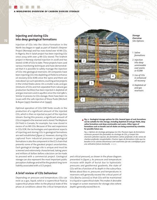
Storage<br />
Overview<br />
Site Options<br />
1 Saline<br />
formations<br />
2 Injection<br />
into deep<br />
unmineable<br />
coal seams<br />
or ECBM<br />
3 Use of CO2<br />
in enhanced<br />
oil recovery<br />
4 Depleted oil<br />
and gas<br />
reservoirs<br />
Fig. 2: Geological storage options for CO2. Several types of rock formations<br />
can be suitable for CO2 storage, including depleted oil and gas fields, deep<br />
saline formations and deep unmineable coal seams. Other types of<br />
formations such as basalts and oil shales are being examined by scientists<br />
for possible future use.<br />
Fig. 2: Options de stockage géologique du CO2. Plusieurs types de formations<br />
rocheuses peuvent être favorables au stockage de CO2, y compris des<br />
réservoirs pétroliers épuisés, des formations salines profondes et des veines de<br />
charbon profondes inexploitables. D’autres types de formations telles que les<br />
basaltes et les schistes bitumineux sont examinées par des scientifiques pour<br />
une utilisation future éventuelle. © GCCSI.<br />
and critical pressure), as shown in the phase diagram<br />
presented in figure 3. As pressure and temperature<br />
increase with depth of burial due to hydrostatic<br />
pressures and geothermal gradients, the state of<br />
CO2 will be a function of its depth in the subsurface.<br />
Below about 800 m, pressures and temperatures in<br />
reservoirs will generally exceed the critical point of<br />
CO2 [Bachu (2000)] so that CO2 will be maintained<br />
in a liquid or supercritical state. This makes it desirable<br />
to target or screen reservoirs for storage sites where<br />
depths generally exceed 800 m.