KESSEL-Kleinkläranlagen InnoClean PLUS
KESSEL-Kleinkläranlagen InnoClean PLUS
KESSEL-Kleinkläranlagen InnoClean PLUS

Create successful ePaper yourself
Turn your PDF publications into a flip-book with our unique Google optimized e-Paper software.
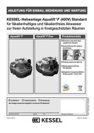
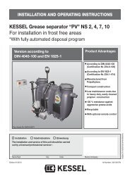
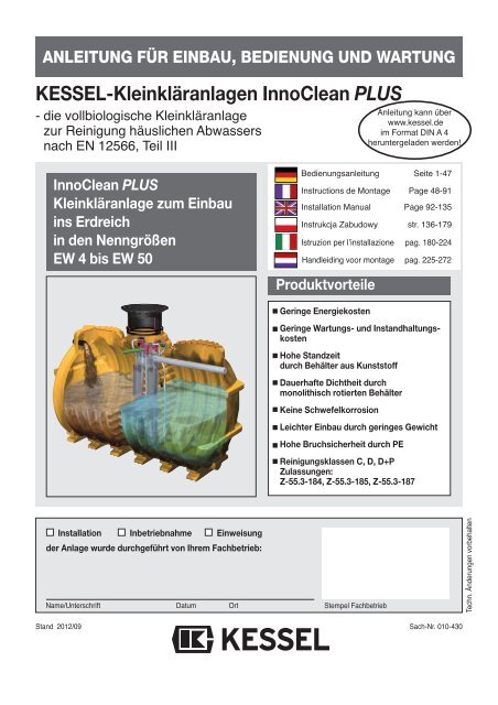
ANLEITUNG FÜR EINBAU, BEDIENUNG UND WARTUNG<br />
<strong>KESSEL</strong>-<strong>Kleinkläranlagen</strong> <strong>InnoClean</strong> <strong>PLUS</strong><br />
- die vollbiologische Kleinkläranlage<br />
zur Reinigung häuslichen Abwassers<br />
nach EN 12566, Teil III<br />
<strong>InnoClean</strong> <strong>PLUS</strong><br />
Kleinkläranlage zum Einbau<br />
ins Erdreich<br />
in den Nenngrößen<br />
EW 4 bis EW 50<br />
Installation Inbetriebnahme Einweisung<br />
der Anlage wurde durchgeführt von Ihrem Fachbetrieb:<br />
Name/Unterschrift Datum Ort<br />
Stand 2012/09<br />
Bedienungsanleitung Seite 1-47<br />
Instructions de Montage Page 48-91<br />
Installation Manual Page 92-135<br />
Produktvorteile<br />
Geringe Energiekosten<br />
Geringe Wartungs- und Instandhaltungskosten<br />
Hohe Standzeit<br />
durch Behälter aus Kunststoff<br />
Dauerhafte Dichtheit durch<br />
monolithisch rotierten Behälter<br />
Keine Schwefelkorrosion<br />
Leichter Einbau durch geringes Gewicht<br />
Hohe Bruchsicherheit durch PE<br />
Reinigungsklassen C, D, D+P<br />
Zulassungen:<br />
Z-55.3-184, Z-55.3-185, Z-55.3-187<br />
Stempel Fachbetrieb<br />
Anleitung kann über<br />
www.kessel.de<br />
im Format DIN A 4<br />
heruntergeladen werden!<br />
Instrukcja Zabudowy str. 136-179<br />
Istruzion per lʼinstallazione pag. 180-224<br />
Handleiding voor montage pag. 225-272<br />
Sach-Nr. 010-430<br />
Techn. Änderungen vorbehalten
Warnung !<br />
Achtung !<br />
1. Sicherheitshinweise<br />
Achtung! Erstickungsgefahr beim Betreten der Anlage<br />
Das Personal für Montage, Bedienung, Wartung und Reparatur muss die entsprechende Qualifikation<br />
für diese Arbeiten aufweisen.<br />
Der Verantwortungsbereich, die Zuständigkeit und die Überwachung des Personals müssen durch<br />
den Betreiber genau geregelt sein.<br />
Die Betriebssicherheit der gelieferten Anlage ist nur bei bestimmungsgemäßer Verwendung gewährleistet.<br />
Die Grenzwerte der technischen Daten dürfen auf keinen Fall überschritten werden.<br />
Diese Anlage enthält elektrische Spannungen und steuert mechanische Anlagenteile. Bei Nichtbeachtung<br />
der Bedienungsanleitung können erhebliche Sachschäden, Körperverletzungen oder tödliche<br />
Unfälle die Folge sein.<br />
Bei Montage, Bedienung, Wartung und Reparatur der Anlage sind die Unfallverhütungsvorschriften,<br />
die in Frage kommenden DIN- und VDE-Normen und Richtlinien zu beachten.<br />
Dies sind u.a.:<br />
• „Unfallverhütungsvorschriften - Bauarbeiten“ BGV C22 bisher VBG 37<br />
• „Baugruben und Gräben, Böschungen, Arbeitsraumbreite, Verbau“ DIN 4124<br />
• „Verlegung und Prüfung von Abwasserleitungen und -kanälen“ DIN EN 1610<br />
• „Richtlinien für Arbeiten in Behältern und engen Räumen“ BGR 117 bisher ZH1/77<br />
Die Abdeckung der Kleinkläranlage muss gegen unbefugtes Öffnen (insbesondere durch Kinder)<br />
auch während der Arbeitspausen ausreichend gesichert sein.<br />
Die Anlage besteht aus mehreren Komponenten. Beachten Sie deshalb die einzelnen Kapitel in der<br />
Bedienungsanleitung. Bei jeder Montage, Wartung, Inspektion und Reparatur an einer der Komponenten<br />
ist immer die Gesamtanlage durch ziehen des Netzsteckers an der Steuereinheit außer Betrieb<br />
zu setzen und gegen Wiedereinschalten zu sichern. Stellen Sie sicher, dass der Zufluss von Abwasser<br />
während der Montage unterbrochen ist.<br />
Das Steuergerät steht unter Spannung und darf nicht geöffnet werden.<br />
Nur Elektrofachkräfte dürfen Arbeiten an elektrischen Einrichtungen durchführen.<br />
Der Begriff Elektrofachkraft ist in der VDE 0105 definiert.<br />
Arbeiten am Verdichter, die über die im Kapitel Inspektion und Wartung beschriebenen Tätigkeiten<br />
hinausgehen, sind unzulässig.<br />
Es ist sicherzustellen, dass sich die Elektrokabel sowie alle anderen elektrischen Anlagenteile in<br />
einem einwandfreien Zustand befinden. Bei Beschädigung darf die Anlage auf keinen Fall in Betrieb<br />
genommen werden.<br />
Umbau oder Veränderungen der Anlage sind nur in Absprache mit dem Hersteller zu tätigen. Originalersatzteile<br />
und vom Hersteller zugelassenes Zubehör dienen der Sicherheit. Die Verwendung anderer<br />
Teile kann die Haftung für die daraus entstehenden Folgen aufheben.<br />
3
Inhaltsverzeichnis<br />
1. Sicherheitshinweise .......... .............................................................................................. Seite 3<br />
2. Allgemeines 2.1 Einsatzbereich ........................................................................ Seite 6<br />
2.2 Anlagenbeschreibung .............................................................. Seite 6<br />
2.3 Anlagenkonfiguration .............................................................. Seite 7<br />
2.4 Maße und Nutzvolumen .......................................................... Seite 8<br />
2.5 Funktionsbeschreibung ........................................................... Seite 13<br />
3. Verpackung, Transport 3.1 Verpackung.............................................................................. Seite 15<br />
und Lagerung 3.2 Transport................................................................................. Seite 15<br />
3.3 Lagerung ................................................................................. Seite 15<br />
4. Einbau und Montage 4.1 Einbauort................................................................................. Seite 16<br />
4.2 Baugrube................................................................................. Seite 16<br />
4.3 Sauberkeitsschicht.................................................................. Seite 16<br />
4.4 Einsetzen ................................................................................ Seite 17<br />
4.5 Behälter befüllen..................................................................... Seite 17<br />
4.6 Verfüllung Baugrube................................................................ Seite 17<br />
4.7 Verrohrung .............................................................................. Seite 17<br />
4.8 Verlegung der Verbindungsleitungen...................................... Seite 18<br />
4.9 Montage der Aufsatzstücke..................................................... Seite 19<br />
4.10 Befüllen................................................................................... Seite 20<br />
4.11 Einbau Steuereinheit und Verdichter....................................... Seite 21<br />
5. Inbetriebnahme 5.1 Anlage in Betriebsbereitschaft setzen..................................... Seite 24<br />
5.2 Pflichten des Betreibers .......................................................... Seite 25<br />
5.3 Einweisung Kunde .................................................................. Seite 25<br />
6. Betrieb und Entsorgung 6.1 Betrieb..................................................................................... Seite 25<br />
6.2 Eigenkontrolle des Betreibers ................................................. Seite 26<br />
6.3 Was nicht in die biol. Kleinkläranlage gehört ........................... Seite 27<br />
6.4 Entsorgung.............................................................................. Seite 28<br />
7. Wartung 7.1 Vorklärung und Belebung ........................................................ Seite 29<br />
7.2 Verdichter ................................................................................ Seite 30<br />
8. Steuerung der Kleinkläranlage 8.1 Systemmenü........................................................................... Seite 33<br />
8.2 Informationsmenü................................................................... Seite 33<br />
8.3 Wartungsmenü........................................................................ Seite 33<br />
8.4 Einstellungsmenü.................................................................... Seite 34<br />
9. Störungen und Abhilfemaßnahmen ............................................. ................................................... Seite 35<br />
10. Gewährleistung ..... ................................................................................................. Seite 38<br />
11. Anlagenpass und Werkabnahme ....................................................................................................... Seite 39<br />
12. Konformitätserklärung ....................................................................................................... Seite 40<br />
13. Betriebstagebuch ....................................................................................................... Seite 41<br />
14. Wartungscheckliste ....................................................................................................... Seite 42<br />
15. Technische Daten ....................................................................................................... Seite 43<br />
4
Sehr geehrter Kunde,<br />
wir freuen uns, dass Sie sich für ein Produkt von <strong>KESSEL</strong> entschieden haben.<br />
Die gesamte Anlage wurde vor Verlassen des Werkes einer strengen Qualitätskontrolle unterzogen. Prüfen Sie bitte dennoch<br />
sofort, ob die Anlage vollständig und unbeschädigt bei Ihnen angeliefert wurde. Im Falle eines Transportschadens<br />
beachten Sie bitte die Anweisungen in Kapitel „Gewährleistung“ dieser Anleitung.<br />
Diese Einbau-, Bedienungs- und Wartungsanleitung enthält wichtige Hinweise, die bei Montage, Bedienung, Wartung und<br />
Reparatur zu beachten sind. Vor allen Arbeiten an der Anlage müssen der Betreiber sowie das zuständige Fachpersonal<br />
diese Anleitung sorgfältig lesen und befolgen.<br />
<strong>KESSEL</strong> AG<br />
5
2.1 Einsatzbereich<br />
<strong>InnoClean</strong> <strong>PLUS</strong> , die Kleinkläranlage von <strong>KESSEL</strong>, ist eine<br />
Reinigungsanlage für häusliche Abwässer nach EN 12566,<br />
Teil III. Für Niederschlagsabwässer, Abwässer aus der Tierhaltung<br />
sowie Schwimmbadabwässer ist diese Anlage nicht<br />
vorgesehen. In einem biologischen Verfahren, reinigt diese<br />
Kleinkläranlage häusliches Abwasser und passt sich automatisch<br />
den anfallenden Mengen an. Das Abwasser wird je<br />
nach Anlagengröße in einem oder mehreren Kunststoffbehältern<br />
gesammelt und gereinigt. Dieser Behälter ist zum<br />
Verbau im Erdreich vorgesehen. Die Belüftung und Umwäl-<br />
2.2 Anlagenbeschreibung<br />
<br />
<br />
<br />
<strong>KESSEL</strong>-<strong>InnoClean</strong> <strong>PLUS</strong> besteht aus zwei Hauptsegmenten.<br />
Innerhalb eines frostfreien, überflutungssicheren und<br />
trockenen Raumes befindet sich die Steuereinheit; der<br />
Kunststoffbehälter, in dem der Klärungsprozess stattfindet,<br />
wird außerhalb des Gebäudes im Erdreich verbaut.<br />
2. Allgemeines<br />
<br />
<br />
<br />
zung wird von einem Verdichter bereitgestellt und durch eine<br />
Steuereinheit vollautomatisch geregelt. Der Verdichter und<br />
die Steuerung sind zum freien Einbau in frostgeschützten,<br />
überflutungssicheren und trockenen Räumen vorgesehen.<br />
Die Zuleitung muß rückstaufrei an die <strong>InnoClean</strong> <strong>PLUS</strong> angeschlossen<br />
werden. Zusätzlich zu der Kleinkläranlage<br />
muss für eine angemessene Abwasserableitung nach ATV-<br />
DVWK-A138 gesorgt werden. Weiterhin ist in jedem Fall die<br />
Kommune, der Landkreis oder die untere Wasserbehörde für<br />
eine Genehmigung zur Errichtung und den Betrieb der Anlage<br />
zuständig.<br />
<br />
<br />
Steuereinheit (Steuerung und Verdichter)<br />
Zulauf<br />
Vorklärkammer<br />
Belebungskammer<br />
Belüfterkerze<br />
Sickerschacht (optional)<br />
Ventilblock<br />
Klärturm mit integriertem Probenahmebehälter,<br />
Luftheber und Ablauf<br />
Kabelleerrohr<br />
Lüftungsleitung<br />
6
2.3 Anlagenkonfiguration<br />
Seitenansicht<br />
Behälter EW 4 - 6<br />
Nutzvolumen 4800 l<br />
Seitenansicht<br />
Behälter EW 8 -10<br />
Nutzvolumen 7600 l<br />
Frontansicht<br />
7<br />
2. Allgemeines<br />
L
2.4 Maße und Nutzvolumen<br />
Gewicht<br />
(ca. kg)<br />
Höhe<br />
KabelleerKabelrohr (hleer)<br />
leerrohr<br />
(mm)<br />
Höhe<br />
Auslauf Auslauf<br />
(h1)(mm)<br />
(mm)<br />
Höhe<br />
Zulauf Zulauf (h2)<br />
(mm)<br />
(mm)<br />
Grundwasser<br />
(GW) (mm)<br />
(mm)<br />
T EÜ<br />
(mm)<br />
Tiefe Tiefe (T)<br />
GOK bis Sohle Zulauf<br />
(mm)<br />
(mm)<br />
Breite Breite(B)<br />
(mm)<br />
Länge Länge(L)<br />
(mm)<br />
Gesamtvolumen<br />
(l)<br />
Zu-/Ablauf<br />
(DN)<br />
Anzahl<br />
Behälter<br />
Artikelnummer<br />
Reinigungsklasse<br />
C D<br />
maximaler<br />
Schmutzwasserzulauf<br />
(l/Tag)<br />
Einwohnergleichwert<br />
(EW)<br />
Gesamt Behälter 1 Behälter 2 Behälter 3 Behälter 4 Behälter 5 Behälter 6 L 1 L 2 L 3 b1=b2 min max<br />
4 600 97804 RC 97804 RD 1 150 4800 4800 2350 2000 604 1054 T-255 1775 1875 1775 2000 530<br />
6 900 97806 RC 97806 RD 1 150 4800 4800 2350 2000 604 1054 T-255 1775 1875 1775 2000 530<br />
8 1.200 97808 RC 97808 RD 1 150 7600 7600 3470 2000 604 1054 T-255 1775 1875 1775 2000 700<br />
10 1.500 97810 RC 97810 RD 1 150 7600 7600 3470 2000 604 1054 T-255 1775 1875 1775 2000 700<br />
12 1.800 97812 RC 97812 RD 2 150 9600 4800 4800 2350 2350 2000 604 1054 T-255 1775 1875 1775 2000 970<br />
14 2.100 97814 RC 97814 RD 2 150 12400 7600 4800 3470 2350 2000 604 1054 T-255 1775 1875 1775 2000 1130<br />
16 2.400 97816 RC 97816 RD 2 150 12400 7600 4800 3470 2350 2000 604 1054 T-255 1775 1875 1775 2000 1130<br />
18 2.700 97818 RC 97818 RD 2 150 15200 7600 7600 3470 3470 2000 604 1054 T-255 1775 1875 1775 2000 1300<br />
20 3.000 97820 RC 97820 RD 2 150 15200 7600 7600 3470 3470 2000 604 1054 T-255 1775 1875 1775 2000 1300<br />
22 3.300 97822 RC 97822 RD 3 150 18300 5350 7600 5350 2350 3470 2350 2000 604 1054 T-255 1775 1875 1775 2000 1430<br />
2. Allgemeines<br />
24 3.600 97824 RC 97824 RD 3 150 21000 8100 4800 8100 3470 2350 3470 2000 604 1054 T-255 1775 1875 1775 2000 1540<br />
26 3.900 97826 RC 97826 RD 3 150 21000 8100 4800 8100 3470 2350 3470 2000 604 1054 T-255 1775 1875 1775 2000 1540<br />
28 4.200 97828 RC 97828 RD 3 150 23800 8100 7600 8100 3470 3470 3470 2000 604 1054 T-255 1775 1875 1775 2000 1700<br />
30 4.500 97830 RC 97830 RD 3 150 23800 8100 7600 8100 3470 3470 3470 2000 604 1054 T-255 1775 1875 1775 2000 1700<br />
32 4.800 97832 RC 97832 RD 6 150 31000 5350 5350 4800 5350 4800 5350 2350 2350 2350 2000 604 1054 T-255 1775 1875 1775 2000 2620<br />
34 5.100 97834 RC 97834 RD 6 150 31000 5350 5350 4800 5350 4800 5350 2350 2350 2350 2000 604 1054 T-255 1775 1875 1775 2000 2620<br />
36 5.400 97836 RC 97836 RD 6 150 31000 5350 5350 4800 5350 4800 5350 2350 2350 2350 2000 604 1054 T-255 1775 1875 1775 2000 2620<br />
38 5.700 97838 RC 97838 RD 6 150 36600 5350 5350 7600 5350 7600 5350 2350 3470 2350 2000 604 1054 T-255 1775 1875 1775 2000 2950<br />
40 6.000 97840 RC 97840 RD 6 150 36600 5350 5350 7600 5350 7600 5350 2350 3470 2350 2000 604 1054 T-255 1775 1875 1775 2000 2950<br />
42 6.300 97842 RC 97842 RD 6 150 36600 5350 5350 7600 5350 7600 5350 2350 3470 2350 2000 604 1054 T-255 1775 1875 1775 2000 2950<br />
8<br />
44 6.600 97844 RC 97844 RD 6 150 36600 5350 5350 7600 5350 7600 5350 2350 3470 2350 2000 604 1054 T-255 1775 1875 1775 2000 2950<br />
46 6.900 97846 RC 97846 RD 6 150 42000 8100 8100 4800 8100 4800 8100 3470 2350 3470 2000 604 1054 T-255 1775 1875 1775 2000 3150<br />
48 7.200 97848 RC 97848 RD 6 150 42000 8100 8100 4800 8100 4800 8100 3470 2350 3470 2000 604 1054 T-255 1775 1875 1775 2000 3150<br />
50 7.500 97850 RC 97850 RD 6 150 42000 8100 8100 4800 8100 4800 8100 3470 2350 3470 2000 604 1054 T-255 1775 1875 1775 2000 3150<br />
Bitte beachten Sie:<br />
witterungsbedingte Einflüsse oder Abkühlung während der Verbauphase (durch Befüllen mit kaltem Wasser),<br />
können bei den Behältern zu Abweichungen von den Maßangaben führen.<br />
Bitte prüfen Sie daher vor Verbau insbesondere die Höhenangaben auf ihr tatsächliches Maß.
Anlagenkonfiguration EW 4, EW 6, EW 8 und EW 10<br />
9<br />
2. Allgemeines<br />
hRmax<br />
hRmin<br />
hRmax hRmin<br />
ARmax ARmin
2. Allgemeines<br />
Anlagenkonfiguration EW 12, EW 14, EW 16 und EW 20<br />
10<br />
hRmax hRmin<br />
ARmax ARmin
Anlagenkonfiguration EW 22 bis EW 30<br />
11<br />
2. Allgemeines<br />
hRmax hRmin ARmax<br />
ARmin
Anlagenkonfiguration EW 32 bis EW 50<br />
2. Allgemeines<br />
12<br />
hRmax hRmin ARmax ARmin
2.5 Funktionsbeschreibung<br />
Der Klärprozess wird vollautomatisch von<br />
der Steuereinheit geregelt. Ein Klärzyklus<br />
dauert ca. 8 Stunden und wird durch<br />
Abführen des geklärten Wassers beendet.<br />
Der Klärungsprozess basiert auf Mikroorganismen,<br />
die während der Behandlungsphase<br />
das Abwasser reinigen.<br />
1. Einleitung des Schwarzwassers<br />
(gesamtes häusliches Abwasser)<br />
Sämtliches häusliches Abwasser gelangt in<br />
die Vorklärkammer. Dort sinken die<br />
Schwerteile zum Boden ab und bilden eine<br />
Schlammschicht. Der Abwasserschlamm<br />
verbleibt in der Vorklärkammer, verdichtet<br />
sich und muss bei Erreichen der maximalen<br />
Aufnahmekapazität entsorgt werden.<br />
2. Füllen der Belebungskammer<br />
(Beschickung)<br />
Die Belebungskammer wird mit dem Abwasser<br />
aus der Vorklärkammer befüllt.<br />
Über den Beschickungsheber wird ein definiertes<br />
Abwasservolumen aus der Vorklärkammer<br />
in die Belebungskammer geführt.<br />
3. Behandlungsphase des Abwassers<br />
(Normal-, Spar- und Urlaubsphase)<br />
In der Belebungskammer wird das Abwasser<br />
mit kurzen Belüfterstößen (Membranrohrbelüfter)<br />
verwirbelt. Durch eine phasenweise<br />
Belüftung gelangt Sauerstoff in<br />
das Abwasser und Mikroorganismen erhalten<br />
Sauerstoff für den Nährstoffabbau.<br />
Dabei bildet sich Belebtschlamm. Der Stoffwechsel<br />
der Mikroorganismen reinigt das<br />
Abwasser.<br />
Die Behandlungsphase dauert in der Regel<br />
ca. sechs Stunden. Darüber hinaus reguliert<br />
sich die Anlage gemäß ihrer Beschickung.<br />
Die Abwasserbehandlung läuft<br />
dann im Rahmen der “Normalphase”, der<br />
“Sparphase” oder der “Urlaubsphase” ab.<br />
(siehe Punkt 6.1)<br />
13<br />
2. Allgemeines
4. Absetzphase<br />
Nach der Behandlungsphase folgt eine<br />
zweistündige Absetzphase. Alle in dem Abwasser<br />
enthaltenen Feststoffe, sowie der<br />
Belebtschlamm setzen sich am Beckenboden<br />
ab somit bildet sich im oberen Bereich<br />
eine Klarwasserschicht und am Boden eine<br />
Schlammschicht aus Mikroorganismen.<br />
5. Abziehen des Klarwassers<br />
(Klarwasserabzug)<br />
Oberhalb dieser Schlammschicht verbleibt<br />
nun gesäubertes Wasser das über den Luftheber<br />
für den Klarwasserabzug in die Vorflut<br />
oder Versickerung geführt wird.<br />
6. Rückpumpen des Belebtschlamms<br />
(Schlammabzug)<br />
Überschüssiger Belebtschlamm wird in die<br />
Vorklärung zurückgehoben.<br />
2. Allgemeines<br />
14
3. Verpackung, Transport und Lagerung<br />
Das Kapitel Sicherheitshinweise ist zu beachten!<br />
3.1 Verpackung<br />
Eine Verpackung der Behälter zum Zwecke des Transports<br />
bzw. der Lagerung ist bei Beachtung der nachfolgenden<br />
Punkte nicht notwendig.<br />
Hinweis: Der Eintrag von Fremdkörpern (Schmutz, Staub<br />
etc.) während der Verbauphase in die Kläranlage ist zu vermeiden.<br />
Ggf. sind an allen Öffnungen Abdeckungen anzubringen.<br />
3.2 Transport<br />
• Der Transport ist nur von solchen Firmen durchzuführen,<br />
die über fachliche Erfahrungen, geeignete Geräte, Einrichtungen<br />
und Transportmittel, sowie ausreichend geschultes<br />
Personal verfügen.<br />
• Die Behälter müssen so transportiert werden, daß sie nicht<br />
unzulässig belastet werden und dass eine Lageveränderung<br />
während des Transports ausgeschlossen ist. Im Falle<br />
einer Verspannung ist diese so vorzunehmen, dass eine<br />
Beschädigung der Behälter ausgeschlossen ist (z.B. Verwendung<br />
von Gewebe- oder Schlaufengurten). Die Verwendung<br />
von Drahtseilen oder Ketten ist nicht zulässig.<br />
• Beim Abheben, Verfahren und Absetzen der Behälter müssen<br />
stoßartige Beanspruchungen vermieden werden.<br />
Kommt ein Gabelstapler zum Einsatz, müssen während der<br />
Fahrt mit dem Gabelstapler die Behälter gesichert werden.<br />
Ein Rollen oder Schleifen der Behälter über den Untergrund<br />
ist nicht zulässig. Auf der Ladefläche eines LKW darf<br />
der Behälter für Zwecke der Be- und Entladung geschoben<br />
und gezogen werden.<br />
15<br />
• Die Behälter sind gegen unzulässige Lageveränderungen<br />
während der Beförderung zu sichern. Durch die Art der Befestigung<br />
dürfen die Behälter nicht beschädigt werden.<br />
3.3 Lagerung<br />
Sollte eine Lagerung der Behälter vor dem Einbau erforderlich<br />
sein, so darf diese nur kurzzeitig und auf ebenem, von<br />
scharfkantigen Gegenständen befreitem Untergrund geschehen.<br />
Bei Lagerung im Freien sind die Behälter gegen<br />
Beschädigung, Sturmeinwirkung und Verschmutzung zu<br />
schützen.
Während der Zwischenlagerung der Kleinkläranlage<br />
sowie bis zum Abschluss der Einbauarbeiten, müssen<br />
an der Baustelle geeignete Sicherungsmaßnahmen getroffen<br />
werden, um Unfälle und Beschädigungen der<br />
Kleinkläranlage zu verhindern.<br />
Das Kapitel Sicherheitshinweise ist zu beachten.<br />
Einbauvoraussetzungen<br />
Der Einbau ist nur von solchen Firmen durchzuführen, die<br />
über fachliche Erfahrungen, geeignete Geräte und Einrichtungen<br />
sowie ausreichend geschultes Personal verfügen.<br />
Eine Erfassung der Bodenbeschaffenheit im Hinblick auf die<br />
bautechnische Eignung muss vorgenommen worden sein<br />
(Bodenklassifikation für bautechnische Zwecke DIN 18196).<br />
Der maximal auftretende Grundwasserstand muss ebenso<br />
vor Beginn der Bauarbeiten festgestellt werden. Eine ausreichende<br />
Ableitung (Drainage) von Sickerwässern ist bei<br />
wasserundurchlässigen Böden zwingend notwendig. Die<br />
auftretenden Belastungsarten wie max. Verkehrslasten und<br />
Einbautiefe müssen abgeklärt sein.<br />
Kurzübersicht Einbauschritte (siehe auch 4.1 bis 4.12)<br />
1. Einbauort festlegen.<br />
2. Baugrube ausheben.<br />
3. Sauberkeitsschicht (Behälterbett) erstellen.<br />
4. Behälter in die Baugrube einsetzen.<br />
5. Behälter in allen Kammern bis zur Hälfte mit Wasser befüllen,<br />
um Standsicherheit zu gewährleisten.<br />
6. Baugrube mit Kies (bis unter den Auslauf) lagenweise<br />
verfüllen und verdichten.<br />
7. Verrohrung der Zu- und Abläufe, sowie der Lüftungsleitung<br />
und Kabelleerrohrleitung.<br />
8. Belüftungsschlauch und Steuerleitung im Kabelleerrohr<br />
verlegen.<br />
9. Aufsatzstück aufsetzen und mit Klemmring fixieren.<br />
10. Abschließende Befüllung des Behälters.<br />
11. Wandkonsole, Verdichter und Steuerung montieren und<br />
anschließen.<br />
12. Inbetriebnahme der Anlage (siehe Kapitel 5).<br />
4.1 Einbauort<br />
Unmittelbar vor dem Einbringen des Behälters in die Baugrube<br />
hat der Sachkundige der mit dem Einbau beauftragten<br />
Firma folgendes zu prüfen und zu bescheinigen:<br />
- Die Unversehrtheit der Behälterwand;<br />
- den ordnungsgemäßen Zustand der Baugrube, insbesondere<br />
hinsichtlich der Abmessungen und Sohlenbettung;<br />
- Beschaffenheit der Körnung des Verfüllmaterials.<br />
Die Distanz zwischen Steuereinheit und Behälter darf maximal<br />
12,5 m (Option: 30 m - Schlauchpaket = Distanz 27,5 m)<br />
betragen. Sollte dies nicht ausreichen, so kann die Steuereinheit<br />
und der Verdichter in einem optionalen Schaltschrank<br />
installiert werden.<br />
Der max. Abstand bei Anlagen mit mehreren Behältern beträgt<br />
3,0 m. Sollten Sie diesen Abstand überschreiten, so<br />
sind zusätzliche Schläuche notwendig.<br />
4. Einbau und Montage<br />
4.2 Baugrube<br />
Hinweis: Bei Mehrbehälteranlagen eine Baugrube für alle<br />
Behälter ausheben!<br />
➁<br />
➀<br />
Die größeren <strong>InnoClean</strong> <strong>PLUS</strong> -Anlagen bestehen aus zwei oder mehr Behältern.<br />
Diese lassen sich individuell in verschiedenen Varianten anordnen. So können<br />
schwierigste Einbausituationen leicht gemacht werden.<br />
Der Baugrund muss waagerecht und eben sein, um die Anlage<br />
vollflächig aufstellen zu können. Außerdem muss der<br />
Baugrund eine ausreichende Tragfähigkeit gewährleisten.<br />
Als Unterbau ist ein verdichteter Rundkornkies (Körnung<br />
8/16, Dicke mind. 30 cm, Dpr=95%) und darauf 3 - 10 cm verdichteter<br />
Sand notwendig. Der Abstand zwischen Baugrubenwand<br />
und Behälter muss mindestens 70 cm betragen.<br />
Die Böschungen müssen der DIN 4124 entsprechen.<br />
• Einbau im Gelände mit Hanglage<br />
Beim Einbau der Kleinkläranlage in ein Gelände mit Hanglage<br />
ist unbedingt darauf zu achten, dass der seitlich schiebende<br />
Erddruck bei nicht gewachsenem Boden durch eine<br />
entsprechend ausgelegte Stützmauer abgefangen wird.<br />
• Frostfreie Tiefe<br />
Beachten Sie beim Einbau der Kleinkläranlage unbedingt die<br />
örtlich festgelegte frostfreie Tiefe. Um auch im Winter einen<br />
reibungslosen Betrieb zu gewährleisten, ist beim<br />
Einbau ebenso die Zu- und Ablaufleitung in frostfreier<br />
Einbautiefe zu verlegen. In aller Regel liegt die frostfreie<br />
Tiefe, wenn nicht anders durch die Behörde angegeben, bei<br />
ca. 80 cm.<br />
4.3 Sauberkeitsschicht<br />
Unterbau: Rundkornkies<br />
(Körnung 8/16) nach DIN 4226-1<br />
Behälterbett: Sand<br />
Behälterumhüllung: Rundkornkies<br />
(Körnung 8/16) nach DIN 4226-1<br />
Bereich außerhalb<br />
Behälterumhüllung: Material geeigneter Beschaffenheit<br />
Deckschicht: Humus o.ä. (Belastungsklasse beachten)<br />
16<br />
➁<br />
➀
β nach<br />
DIN 4124<br />
<br />
<br />
≥ 50cm<br />
Unterbau: Rundkornkies (max. Körnung 8/16) nach<br />
DIN 4226-1 verdichtet mit Dpr=95%<br />
Behälterbett: verdichteter Sand<br />
Behälter<br />
Behälterumhüllung: Rundkornkies (max. Körnung<br />
4.4 Einsetzen<br />
Der Behälter ist mit Hilfe einer geeigneten Vorrichtung<br />
stoßfrei in die Baugrube einzubringen und auf die Sohlenbettung<br />
aufzusetzen (siehe auch Kapitel „Transport“).<br />
Fließrichtung und Fließrichtungspfeile auf dem Behälter beachten!<br />
4.5 Behälter befüllen<br />
Behälter in beiden Kammern mit Klarwasser befüllen (ca. 80<br />
cm) um eine bessere Standfestigkeit zu erlangen.<br />
4.6 Verfüllung Baugrube<br />
Generell sollte das Befüllen des Behälters und die Verfüllung<br />
der Baugrube parallel ausgeführt werden. Die Verfüllung der<br />
Baugrube erfolgt bis Unterkante Zu- und Ablauf, sowie der<br />
Lüftungs- und Kabelleerrohrleitung. Die Behälterumhüllung<br />
muss in einer Breite von mindestens 50 cm hergestellt werden.<br />
Die einzelnen Lagen des Verfüllmaterials sollten nicht<br />
höher als 30 cm sein. Sie sind mit leichten Verdichtungs-<br />
4. Einbau und Montage<br />
<br />
17<br />
<br />
≥ 50cm<br />
≥ 70cm ≥ 70cm<br />
<br />
≤ 20cm<br />
≤ 30cm<br />
≤ 30cm<br />
≤ 30cm<br />
≤ 30cm<br />
≤ 30cm<br />
≤ 30cm<br />
≤ 30cm<br />
≤ 30cm<br />
≤ 30cm<br />
3-10cm<br />
8/16) nach DIN 4226-1 verdichtet mit Dpr=95%<br />
Bereich außerhalb Behälterumhüllung:<br />
Material geeigneter Beschaffenheit<br />
Deckschicht: Humus, Straßenbelag, Beton o.ä.<br />
geräten zu verdichten (mind. Dpr=95%). Eine Beschädigung<br />
der Behälterwand und eine Verlagerung der Behälter während<br />
und nach dem Einbau muss ausgeschlossen werden.<br />
4.7 Verrohrung<br />
Einen Vorschlag zur Verlegung der Rohrleitungen finden Sie<br />
auf den Seiten 268-271. Die Zu-/Ablaufleitungen, sowie Verbindungsleitungen<br />
sind frostfrei (siehe 4.2) zu verlegen und<br />
anzuschließen, sobald die Baugrube bis zur Unterkante der<br />
Zu- und Ablaufleitung verfüllt und verdichtet ist.<br />
Der Übergang von Fallleitungen in horizontale Leitungen ist<br />
mit zwei 45°-Bogenformstücken und einem mindestens<br />
250 mm langen Zwischenstück auszuführen. Vor dem Inno-<br />
Clean <strong>PLUS</strong> -Behälter ist eine Beruhigungsstrecke vorzusehen,<br />
deren Länge mindestens dem 10-fachen der Nennweite<br />
der Rohrleitung entspricht. Für die Ausbildung des<br />
Zulaufes ist das Zulaufrohr bauseits 20 cm in die Zulauföffnung<br />
einzu-schieben. Das Auslaufrohr kann mittels Muffenrohrverbindung<br />
an die Grundleitung angeschlossen werden.<br />
• Kabelleerrohr<br />
Für die Leitungsverbindung zwischen Steuergerät/Kompressor<br />
und Ventilblock/<strong>InnoClean</strong> <strong>PLUS</strong> -Behälter muss ein<br />
Kabelleerrohr (KG-Rohr aus PVC-U in der Dimension DN<br />
100) verlegt werden. Das Leerrohr sollte über seine gesamte<br />
Länge über ein stetiges Gefälle von ≥ 2° zum Behälter ver-
Betondecke<br />
Kabelleerrohrabdichtung<br />
Art. Nr. 97 711<br />
handelsübliche<br />
Wanddurchführung<br />
z. B. Fa. Steelter oder<br />
Fa. DOYMA DN 100<br />
fügen. Für die Durchführung durch die Gebäudewand empfiehlt<br />
<strong>KESSEL</strong> auf handelsübliche Wanddurchführungen<br />
zurück zu greifen (siehe Bild). Zur Abdichtung des Kabelleerrohres<br />
im Gebäude, sollte die Abdeckung von <strong>KESSEL</strong><br />
(Kabelleerrohrabdichtung Art.-Nr. 97711) zum Schutz vor<br />
Geruchsbelästigungen eingesetzt werden.<br />
Richtungsänderungen sollten über Bogenformstücke mit maximal<br />
30° Abwinkelung realisiert werden.<br />
Achtung: Alle Leitungen sollten temporär bis zum endgültigen<br />
Anschluß, mit Klebeband verschlossen werden, um<br />
Schmutzeintrag während des Durchschiebens zu vermeiden.<br />
Bemerkung:<br />
Die Behälter können im Bereich der Dome angebohrt werden,<br />
um zusätzliche Anschluß- und Lüftungsleitungen herzustellen.<br />
Hierzu sind Original-Bohrkronen und Rohrdurchführungsdichtungen<br />
von <strong>KESSEL</strong> zu verwenden (<strong>KESSEL</strong>-<br />
Bohrkronen DN 50 - DN 150, Art.-Nr. 50100,<br />
<strong>KESSEL</strong>-Rohrdurchführungsabdichtungen:<br />
DN 50 Art.-Nr. 850114<br />
DN 70 Art.-Nr. 850116<br />
DN 100 Art.-Nr. 850117<br />
DN 125 Art.-Nr. 850118<br />
DN 150 Art.-Nr. 850119)<br />
Die Bohrungen sollten auf möglichst planen Flächen erfolgen.<br />
Für eine optimale Abdichtung der Bohrung sollte der<br />
Abstand zwischen dem Rand der Bohrung und unebener<br />
Kontur mindestens 15 mm betragen, damit die Dichtung umlaufend<br />
gleichmäßig um die Bohrung anliegt.<br />
• Entlüftung<br />
Die Be- und Entlüftung der Anlage erfolgt über eine Lüftungsleitung<br />
der Größe DN 100 und wird an der entsprechenden Öffnung<br />
am Dom angeschlossen. Eine zusätzliche Lüftungsleitung<br />
kann am Dom angeschlossen werden (siehe Abb. S. 5).<br />
Hierzu ist die entsprechende Bohrkrone und Rohrdurch-<br />
4. Einbau und Montage<br />
Kellerwand<br />
Gefälle mind. 2°<br />
fallend zum Behälter<br />
KG-Rohr DN 100<br />
führungsdichtung von <strong>KESSEL</strong> zu verwenden . <strong>KESSEL</strong> empfiehlt<br />
die Verwendung eines Aktivkohlefilters zur Vermeidung<br />
von Geruchsbelästigung.<br />
Hinweis für die Nenngrößen EW 12 bis EW 30<br />
Für die künftige Belüftung des Belebtschlammes ist bei den<br />
Anlagen EW 12 bis EW 20 bauseits die Belüfterkerze in die<br />
Belebungskammer des Behälters einzubringen.<br />
Dazu ist die Belüfterkerze über den Luftschlauch auf die<br />
Sohle des Behälters (Belebungskammer) herabzulassen<br />
und mittig in Längsrichtung auszurichten. Analog sind bei<br />
Anlagen der Nenngrößen EW 22 bis EW 30 die Belüfterkerzen<br />
vor Befüllen der Tanks im 3. Behälter in Längsrichtung<br />
einzulegen.<br />
18<br />
Dichtung<br />
Art.-Nr. 860116<br />
Dichtung für<br />
Rohrdurchführung<br />
Behälterwand<br />
<strong>InnoClean</strong> <strong>PLUS</strong><br />
Ventilblock<br />
<strong>InnoClean</strong> <strong>PLUS</strong>
4.8 Verlegung der Verbindungsleitungen zur Steuereinheit<br />
(Belüftungsschlauch und Steuerleitung)<br />
Die Steuerleitung, sowie der Belüftungsschlauch sind zwischen<br />
Ventilblock und Steuereinheit im Kabelleerrohr zu verlegen<br />
( siehe Vorgehen).<br />
Vorgehen:<br />
- Öffnen des Verriegelungsbügels am Ventilblock im Behälter<br />
- Entnahme des Ventilblocks von der Adapterplatte<br />
- grauen Belüftungsschlauch und Steuerleitung durch das<br />
Kabelleerrohr ziehen<br />
- Belüftungsschlauch mittels Schnellverbinder am Ventilblock<br />
anschließen (siehe 4.11 Punkt 5)<br />
- Ventilblock auf Adapterplatte einsetzen<br />
Adapterplatte<br />
Lasche zum<br />
Einhängen der<br />
Steuerleitung<br />
Steuerleitung<br />
Luftschläuche zu den Drucklufthebern<br />
Luftschlauch zum Verdichter<br />
4. Einbau und Montage<br />
Schnellverbinder Ventilblock<br />
4.9 Montage der Aufsatzstücke Zuerst die Dichtung (siehe Zeichnung 4.9) in die vorgesehene<br />
Sicke im Dom einlegen.<br />
Das teleskopische <strong>KESSEL</strong>-Aufsatzstück im unteren Bereich<br />
mit Gleitmittel einfetten und in die Behälteröffnung einstecken,<br />
in die gewünschte Position bringen. Alternativ kann<br />
Gleitmittel auch auf den Dichtring aufgetragen werden.<br />
Mit Hilfe des Klemmringes (optionales Zubehör) kann nun<br />
das Aufsatzstück in der gewünschten Position (Ausrichtung<br />
an der Geländeoberkante) fixiert werden. Die Feinjustierung<br />
Klemmring<br />
(optionales Zubehör)<br />
19<br />
Verriegelungsbügel<br />
- Achtung: Steuerleitung muss in vorgesehene Lasche eingeklipst<br />
werden (siehe Abb.) um ein korrektes Verriegeln<br />
mit der Adapterplatte zu gewährleisten.<br />
- Ventilblock auf korrekten Sitz prüfen und Verriegelungsbügel<br />
schließen<br />
auf die endgültige Höhe erfolgt dann mittels der Stellschrauben.<br />
Bodenneigungen können durch das stufenlos höhenverstellbare<br />
und bis 5° neigbare Aufsatzstück ausgeglichen werden.<br />
Die mitgelieferten Aufkleber der “Innofanten” sind auf die<br />
gereinigte und trockene Innenfläche am Aufsatzstück anzubringen<br />
(siehe Bild).<br />
Wichtig: Der grüne “Innofant” ist auf die Zulaufseite zu kleben<br />
und der rote auf die Auslaufseite!<br />
Anschließend das Aufsatzstück ausreichend verfüllen und<br />
verdichten.
4. Einbau und Montage<br />
Die Dichtlippe soll auf der Innenseite des<br />
Ringes nach unten zeigen.<br />
Zulauf ➔ ➔ Auslauf<br />
4.10 Abschließende Befüllung des Behälters<br />
Vor dem Verfüllen nochmaliges Kontrollieren der Zu- und Ablaufleitung, sowie der Entlüftungsleitung und des Kabelleerrohrs.<br />
Das Aufsatzstück mit der Geländeoberkante abgleichen.<br />
20
4. 11 Einbau der Steuereinheit und des Verdichters<br />
Beachten Sie bitte, daß für die Anschlussleitungen vom<br />
Behälter zur Steuereinheit ein Kabelleerrohr (DN 100) verlegt<br />
werden muss (siehe 4.7).<br />
Allgemeine Hinweise<br />
ACHTUNG: <strong>KESSEL</strong> empfiehlt, für die Ausführung von<br />
elektrischen Anschlüssen, einen Fachbetrieb des Elektrohandwerks<br />
zu beauftragen. Nehmen sie die Anlage<br />
erst nach vollständigem Einbau in Betrieb. Während der<br />
Anschlussarbeiten darf die Anlage nicht ans Netz angeschlossen<br />
sein.<br />
Steuerung und Verdichter sind in einem frostgeschützten,<br />
überflutungssicheren und trockenen Raum zu montieren.<br />
Rückstausichere Montage beachten!<br />
Auf eine gute Belüftung des Raumes in dem der Verdichter<br />
aufgestellt wird ist zu achten. Eine ausreichende Luftzirkulation,<br />
insbesondere auch bei Geräten die innerhalb eines<br />
Außenschaltschrankes untergebracht werden sollen, ist zu<br />
achten, um den Verdichter vor Überhitzung zu schützen.<br />
Eine kühle Umgebungstemperatur sichert eine hohe Lebensdauer<br />
der Membranen und Ventile.<br />
4. Einbau und Montage<br />
<br />
21<br />
<br />
<br />
<br />
<br />
<br />
Netzanschluss<br />
Verdichter<br />
Wandkonsole<br />
Steuergerät<br />
Netzanschluss Verdichter<br />
Anschlussbuchse für potentialfreien Kontakt<br />
Anschluss Ventilblock<br />
(inkl. Schwimmerschalter)<br />
Anschluss externer Signalgeber<br />
Druckluftanschluss Ventilblock<br />
Anschluss Druckluftsensor<br />
Winkelstück für<br />
Anschluss Druckluftschlauch<br />
Schnellverbinder<br />
Der Verdichter sollte nicht in staubiger Umgebung betrieben<br />
werden. Ein Überhitzen durch verstopfte Filter verkürzt die<br />
Lebensdauer der Membranen und Filter.<br />
Der Verdichter soll vor direkter Sonneneinstrahlung, Regen,<br />
Schnee und Frost geschützt sein. Die angesaugte Umgebungsluft<br />
muss frei von entflammbaren oder aggressiven<br />
Gasen oder Dämpfen sein.<br />
Die Schlauchleitung ist so kurz und so gerade wie möglich<br />
zwischen Steuerung und Behälter zu verlegen. Richtungsänderungen<br />
sind über lange Bögen anstatt engen Abwinkelungen<br />
zu realisieren.<br />
Der Verdichter ist oberhalb der Steuerung auf einem geeigneten<br />
Sockel oder einer Konsole zu platzieren, um evtl.<br />
Schäden zu vermeiden.<br />
Bei der Montage auf einer instabilen Unterlage können durch<br />
Vibrationen störende Geräusche auftreten.<br />
Der Verdichter ist horizontal zu montieren, um eine einseitige<br />
Belastung der Membranen und dadurch verkürzte Lebensdauer<br />
der Komponenten zu verhindern.<br />
Der Verdichter soll auf allen 4 Gummifüßen komplett aufstehen<br />
und soll nicht wackeln.
Montage und Anschluss<br />
<br />
<br />
<br />
<br />
<br />
4. Einbau und Montage<br />
<br />
<br />
<br />
Die Wandkonsole (optionales Zubehör) oder eine<br />
alternative Abstellmöglichkeit ist waagerecht an der<br />
Wand zu fixieren.<br />
Das Steuergerät durch Lösen der vier stirnseitigen<br />
Kreuzschlitzschrauben öffnen und dessen Rückwand<br />
mit den mitgelieferten vier Kreuzschlitzschrauben an<br />
den vorgebohrten Stellen der Wandkonsole (unterhalb<br />
der Abstellfläche für den Verdichter) befestigen.<br />
Anschließend ist der Gehäusedeckel mit max. 1 Nm<br />
wieder zu verschrauben. Achtung: Darauf achten,<br />
dass das Gerät spannungsfrei ist (siehe Sicherheitshinweise<br />
S.2)<br />
Den Verdichter auf der Abstellfläche der Wandkonsole<br />
in die dafür vorgesehenen Vertiefungen stellen.<br />
Bitte beachten Sie, dass die Kontrolllampe nach<br />
vorne gerichtet und der elektrische Anschluss des<br />
Gerätes auf der rechten Seite des Gerätes ist. Der<br />
Netzstecker des Verdichters ist mit der Schuko-Kupplung<br />
am Schaltgerät zu verbinden.<br />
Bevor das Winkelstück für den Anschluss der Druckluftleitung<br />
an den Verdichter am Gerät angeschlossen<br />
wird, ist die mitgelieferte Metallhülse in den langen<br />
Schenkel des Winkelstückes einzuschieben. Anschließend<br />
erfolgt die Montage des Winkelstückes<br />
am Stutzen des Verdichters und dessen Fixierung<br />
mittels der Federklemme am Gerät.<br />
Abweichung bei den Verdichtergrößen EL 150/200/<br />
250: Entfernen Sie den Stutzen beim Verdichter und<br />
Schrauben Sie das mitgelieferte Winkelstück am Gewinde<br />
des Verdichters ein (Gewinde mit Teflonband<br />
o.ä. abdichten). Das Einbringen der Metallhülse entfällt<br />
bei diesen Verdichtergrößen. Schneiden Sie nun<br />
von dem mitgelieferten Luftschlauch ein Stück von 20<br />
cm Länge ab und verbinden Sie damit das Winkelstück<br />
mit dem Schnellverbinder.<br />
Den Schnellverbinder durch Drehen der Verschlusskappe um 120° nach links öffnen und das lange Ende<br />
des Winkelstückes bis zum Anschlag einschieben. Die Verschlusskappe durch Rechtsdrehung schließen.<br />
Der transparente Schlauch des Druckluftsensors ist mit dem Steuergerät an der dritten Buchse von links anzuschließen.<br />
Hierfür die schwarze Überwurfmutter lösen und den innenliegenden Klemmring entnehmen, danach<br />
die Überwurfmutter und den Klemmring auf den transparenten Schlauch aufschieben, anschl. Schlauch<br />
aufstecken. Zum Schluss schwarze Überwurfmutter handfest anschrauben.<br />
Für den Anschluss der Druckluftleitung aus dem Behälter ist der graue Belüftungsschlauch im Kabelleerrohr<br />
auf passende Länge zu kürzen und ohne Abwinkelungen mit dem Schnellverbinder am Verdichter zu fixieren.<br />
Achtung: Belüftungsschlauch locker, nicht auf Spannung verlegen.<br />
Das Anschlusskabel vom Ventilblock ist in die entsprechende Buchse am Steuergerät einzustecken und mit<br />
der Verschraubung zu fixieren.<br />
22
SICHERUNG<br />
Fuse<br />
Fusible<br />
230VAC 50Hz<br />
3,15 AT<br />
NETZ<br />
Mains<br />
Réseau<br />
230VAC 50Hz<br />
PUMPE<br />
Pump<br />
Pompe<br />
230VAC 50Hz<br />
max: 1,0 A<br />
br<br />
L<br />
br<br />
L<br />
bl<br />
N<br />
bl<br />
N<br />
F1<br />
PE<br />
PE<br />
X1<br />
X2<br />
4. Einbau und Montage<br />
Optionale Anschlüsse am Schaltgerät:<br />
Achtung: Alle optionalen Anschlüsse sind nur durch Elektrofachkräfte durchzuführen.<br />
Q1 Q2 Q3 Q4 Q5<br />
23<br />
X5<br />
bl<br />
-<br />
or<br />
+<br />
br bl<br />
or or or<br />
X3 X4<br />
I2 IC PE<br />
X6<br />
1<br />
or or or or or<br />
RxTx MRRIGND<br />
ALARM<br />
Alarm<br />
Alarme<br />
POTENTIALFREIER<br />
KONTAKT<br />
Potential free<br />
switch contact<br />
Connexion libres<br />
de contact<br />
max: 42V 0,5A<br />
SCHWIMMER<br />
floater<br />
flotteur<br />
230V 50Hz
Einweisung / Übergabe<br />
<br />
Das Kapitel Sicherheitshinweise ist zu beachten! (S.2)<br />
Die Inbetriebnahme wird von einem Fachbetrieb oder einem<br />
<strong>KESSEL</strong>-Beauftragten durchgeführt (gegen Aufpreis).<br />
Folgende Personen sollten bei der Übergabe anwesend sein:<br />
- Abnahmeberechtigter des Bauherrn<br />
- Fachbetrieb<br />
Ferner empfehlen wir die Teilnahme des Bedienungspersonals/<br />
Betreibers, Entsorgungsunternehmens<br />
Übersicht Einweisung:<br />
5. 1. Anlage in Betriebsbereitschaft setzen<br />
5. 2. Kontrolle der Anlage<br />
5. 3. Einweisung anhand der Einbau- und Bedienungsanleitung<br />
5. 4. Erstellung des Übergabeprotokolls. (siehe Kapitel 13)<br />
Nach Beendigung der Einweisung ist die Anlage in betriebsbereiten<br />
Zustand zu setzen.<br />
5.1 Anlage in Betriebsbereitschaft setzen<br />
Die Anlage ist vor Inbetriebnahme vollständig zu reinigen<br />
(einschließlich Zu- und Abläufe); Fest- und Grobstoffe sind zu<br />
entfernen.<br />
Die Anlage ist bis zu einer Höhe von 1,20 m in beiden Kammern<br />
mit klarem Wasser zu befüllen. Netzstecker des Steuergerätes<br />
in die Steckdose stecken. Die Anlage initialisiert sich selbständig.<br />
<br />
<br />
5. Inbetriebnahme<br />
<br />
Display/Anzeigenfeld<br />
Bewegungstasten/Richtungstasten<br />
für die Führung durch das Programm-Menü<br />
Bestätigungstaste/OK-Taste<br />
Zurücktaste/ESC-Taste<br />
Kontrolllampe für Betriebsbereitschaft<br />
Kontrolllampe für Störungsmeldung<br />
Netzabschlusskabel<br />
Netzanschluss für Verdichter<br />
Anschluss Druckluftsensor<br />
Anschlussmöglichkeiten<br />
für externen Signalgeber<br />
Anschlus für Ventilblock<br />
Anschlussbuchse für potentialfreien Kontakt<br />
Hinweis: Die Netzleitung muss mit einem FI-Schutzautomaten<br />
ausgerüstet sein.<br />
0.<br />
Systemstart<br />
Systemdiagnose<br />
1.5 Systeminfo<br />
Uhrzeit: 20:45<br />
Schwimmer: S1 S2<br />
Ereignisse: Netzausfall<br />
Normalphase<br />
24<br />
0.1 Sprache<br />
deutsch<br />
französisch<br />
englisch<br />
0.2 Datum/Uhrzeit<br />
Datum<br />
01.01.2009 Uhrzeit<br />
12:00<br />
0.3 Klassen<br />
C<br />
D<br />
0.4 Nenngrößen<br />
EW4<br />
EW6<br />
EW8<br />
EW10<br />
…<br />
EW24
Bei der Erstinitialisierung der Anlage fragt das Steuergerät<br />
nach vier Grundeinstellungen. Im Display des<br />
Steuergerätes erscheint die Frage nach:<br />
1. der Sprache für die Benutzerführung<br />
2. dem Datum und der Uhrzeit<br />
3. der gewünschten Reinigungsklasse C oder D<br />
4. der erforderlichen Nenngröße der Anlage.<br />
Durch Betätigen der Bewegungstasten / Richtungstasten<br />
kann die gewünschte Einstellung über einen Markierungsbalken<br />
gekennzeichnet werden und die Anschließende<br />
Betätigung der Bestätigungstaste hinterlegt die gewählte<br />
Einstellung im Systemspeicher. Sobald die 4 Voreinstellungen<br />
vorgenommen wurden, lädt das Steuergerät den Programmspeicher<br />
und geht selbständig in den Betriebsmodus.<br />
Die Anlage ist jetzt betriebsbereit.<br />
Hinweise zur Schlammrückführung:<br />
Die Belebtschlammrückführung ist erforderlich, um die<br />
Bildung einer zu großen Menge an Belebtschlamm zu vermeiden.<br />
Eine zu große Menge an Belebtschlamm könnte<br />
zu Störungen im Auslauf der Kläranlage führen und eventuell<br />
vorhandene Versickerungsanlagen beeinträchtigen.<br />
Die rückgeführte Schlammmenge sedimentiert in der Vorklärkammer<br />
und wird mit der nächsten Primärschlammentsorgung<br />
abgeführt.<br />
Die Steuerung der Schlammrückführung kann über die<br />
Zeiten T20 & T21 eingestellt werden. Nach der Inbetriebnahme<br />
der Anlage sollten beide Schlammrückführungen<br />
für die ersten 3 bis 5 Monate unterbunden werden, um<br />
einen schnelleren Aufbau der Biologie zu gewährleisten.<br />
6.1 Betrieb<br />
Nach Inbetriebnahme der Anlage bildet sich nach 3-6 Monaten<br />
eine aktive Belebtschlammschicht mit Mikroorganismen<br />
in der Belebungskammer. Mikroorganismen müssen dieser<br />
Anlage nicht zugeführt werden. Eine Zuführung von Belebtschlamm<br />
aus dem nächstgelegenen Klärwerk erachten wir<br />
jedoch als sinnvoll. Wichtig: Belebtschlamm ausschließlich in<br />
die Belebungskammer geben!<br />
Zum reibungslosen Betrieb sind die Wartungsintervalle unbedingt<br />
einzuhalten. Die rechtzeitige Entleerung der Vorklärkammer<br />
muss gewährleistet sein.<br />
Der Betrieb der Kleinkläranlage läuft vollautomatisch ab. Im<br />
Einzelnen sind dies drei Phasen, die “Normal”-, “Spar”-, und<br />
“Urlaubsphase”. Diese unterscheiden sich bezüglich ihrer<br />
Belüftungszeit und Menge. Die eigentliche Klärung findet in<br />
der Normalphase (6 Stunden) statt.<br />
Bei nicht ausreichender Beschickung der Anlage (zu geringer<br />
Schmutzwasserzulauf) geht diese selbständig in die<br />
“Sparphase” (2 Stunden) über. In dieser Phase wird aufgrund<br />
der geringeren Abwassermenge die Belüftungszeit re-<br />
5. Inbetriebnahme<br />
6. Betrieb und Entsorgung<br />
25<br />
Darüber hinaus kann es sinnvoll sein, nach jeder Primärschlammentsorgung<br />
(siehe Punkt 6.4 Entsorgung) die<br />
Einstellung T20 ("Rückführung Urlaubsphase") zu reduzieren<br />
um einen übermäßigen Austrag an Belebtschlamm<br />
zu vermeiden. Für gute Reinigungsergebnisse sollten Sie<br />
sicherstellen, dass sich je nach Betriebsbedingungen,<br />
zwischen 300 ml/l bis 600 ml/l Belebtschlamm im Belebungsbecken<br />
befindet. Sollte dieser Wert nicht erreicht<br />
sein, reduzieren oder erhöhen Sie die voreingestellten<br />
Werte der Schlammrückführung. In der Tabelle auf Seite<br />
31 finden Sie die von Werk voreingestellten Werte.<br />
5.2 Pflichten des Betreibers<br />
Kontrolle<br />
- Transport- oder Montageschäden<br />
- bauliche Mängel<br />
- aller elektrischen und mechanischen Komponenten auf<br />
Sitz und Funktion prüfen<br />
- Schwimmerfunktion<br />
- Schlauchanschlüsse<br />
- Prüfung der Leitungsverbindungen<br />
- der Heber (siehe Punkt 8)<br />
- Belüfterkerze<br />
5.3. Einweisung des Kunden anhand der Einbauanleitung<br />
- Einbau- und Bedienungsanleitung mit Kunde durchgehen<br />
- Bedienung der Anlage (Erklären und Beschreiben)<br />
- Aufklärung des Kunden über die Pflichten des Betreibers<br />
(Entsorung, Wartung, Betrieb einer biologischen Kleinkläranlage,<br />
Betriebstagebuch)<br />
duziert, um ein “aushungern” der adaptierten Mikroorganismen<br />
zu verhindern. Bei längerem Verbleib in der “Sparphase”<br />
(8 Stunden) schaltet sich automatisch die “Urlaubsphase”<br />
ein.<br />
Die “Urlaubsphase” zeichnet sich durch eine noch geringere<br />
Sauerstoffzufuhr aus. Ergänzend dazu wird am Ende der Urlaubsphase<br />
eine definierte Schlammmenge von der Belebtkammer<br />
in die Vorklärung gefördert. Dies ermöglicht beim<br />
nächsten Beschicken eine gewisse Nährstoffzufuhr in die<br />
Belebung. Dies trägt zur Biologieerhaltung bei längerem Stillstand<br />
bei.<br />
Sobald in der Vorklärkammer ausreichend Wasser vorhanden<br />
ist, dass der Schwimmer beim anschließenden Beschicken<br />
eingeschaltet wird, geht die Anlage automatisch in<br />
die Normalphase über.<br />
Diese Anpassung an unterschiedliche Abwassermengen<br />
wird automatisch von der Steuerung geregelt. Die entsprechende<br />
Phase wird am Schaltgerät angezeigt. Eine allgemeine<br />
Übersicht über die entsprechenden Phasen und Zyklen<br />
finden Sie im Kapitel 2.5.
Wenn Sie sich an nachfolgende Empfehlungen halten, können<br />
Sie unnötige Reparaturkosten vermeiden und die Lebensdauer<br />
Ihrer Anlage erhöhen:<br />
• Die Anlage muss ständig eingeschaltet bleiben, auch<br />
während Sie sich im Urlaub befinden.<br />
• Fremdwasser, wie Regen-, Grund-, Schwimmbad- und<br />
Aquarienwasser darf nicht eingeleitet werden.<br />
• Bei Haushaltsreinigern beachten Sie bitte, dass diese keine<br />
sauren oder alkalischen Reaktionen zeigen. Wir empfehlen<br />
biologische abbaubare Reiniger und Waschmittel.<br />
• Die Deckel der Anlage müssen sich öffnen lassen.<br />
• Sorgen Sie dafür, dass die Anlage regelmäßig durch eine<br />
Fachfirma gewartet wird.<br />
• Nur die Vorklärung muss regelmäßig (ca. alle 12-24 Monate)<br />
durch ein Entsorgungsunternehmen entschlammt<br />
werden! Nach Rücksprache mit den zuständigen Wasserbehörden<br />
und Abschluss eines Wartungsvertrages kann<br />
dies aber auch ggf. bedarfsgerecht erfolgen.<br />
Hinweis: Bei Außerbetriebnahme muss sicher gestellt werden,<br />
dass die Anlage weiterhin gefüllt bleibt.<br />
Unbedingt beachten:<br />
Sie können weiterhin alle Reinigungs- und Waschmittel<br />
benutzen - aber bitte die Dosierungsvorschriften<br />
der Hersteller beachten!<br />
Auch verschiedene Rohrreiniger sind, wenn die Dosierung<br />
nach Herstellerangaben eingehalten wird,<br />
verwendbar.<br />
Allerdings sterben bei jeder Einleitung dieser Reinigungsmittel<br />
eine Anzahl an Bakterien ab. Wenn möglich,<br />
bitte auf biologisch abbaubare Reiniger zurückgreifen<br />
und auf die Verwendung von Rohrreinigungsmitteln<br />
verzichten (siehe 6.3).<br />
Hinweise zur Schlammrückführung:<br />
Die Belebtschlammrückführung ist erforderlich, um die<br />
Bildung einer zu großen Menge an Belebtschlamm zu<br />
vermeiden. Eine zu große Menge an Belebtschlamm<br />
könnte zu Störungen im Auslauf der Kläranlage führen<br />
und eventuell vorhandene Versickerungsanlagen beeinträchtigen.<br />
Die rückgeführte Schlammmenge sedimentiert<br />
in der Vorklärkammer und wird mit der nächsten<br />
Primärschlammentsorgung abgeführt.<br />
Die Steuerung der Schlammrückführung kann über die<br />
Zeiten T20 & T21 eingestellt werden. Nach der Inbetriebnahme<br />
der Anlage sollten beide Schlammrückführungen<br />
für die ersten 3 bis 5 Monate unterbunden werden, um<br />
einen schnelleren Aufbau der Biologie zu gewährleisten.<br />
Darüber hinaus kann es sinnvoll sein, nach jeder Primärschlammentsorgung<br />
(siehe Punkt 6.4 Entsorgung) die<br />
Einstellung T20 ("Rückführung Urlaubsphase") zu reduzieren<br />
um einen übermäßigen Austrag an Belebtschlamm<br />
zu vermeiden. Für gute Reinigungsergebnisse sollten Sie<br />
6. Betrieb und Entsorgung<br />
sicherstellen, dass sich je nach Betriebsbedingungen,<br />
zwischen 300 ml/l bis 600 ml/l Belebtschlamm im Belebungsbecken<br />
befindet. Sollte dieser Wert nicht erreicht<br />
sein, reduzieren oder erhöhen Sie die voreingestellten<br />
Werte der Schlammrückführung. In der Tabelle auf Seite<br />
29 finden Sie die von Werk voreingestellten Werte.<br />
6.2 Eigenkontrolle des Betreibers<br />
Als Betreiber der Kläranlage haben Sie gegenüber der Wasserbehörde<br />
die Pflicht, für einen reibungslosen Betrieb der<br />
Anlage zu sorgen. Betriebsstörungen an biologischen <strong>Kleinkläranlagen</strong><br />
wirken sich negativ auf die Ablaufqualität des<br />
gereinigten Wassers aus. Diese müssen daher umgehend<br />
erkannt und durch Sie selbst oder einen qualifizierten Wartungsbetrieb<br />
beseitigt werden. Um die Eigenkontrollen zu<br />
dokumentieren, sind Sie verpflichtet, ein Betriebstagebuch<br />
zu führen. Am Ende dieses Handbuches finden Sie eine Kopiervorlage,<br />
die alle notwendigen Vorgaben enthält.<br />
Die Wasserbehörde kann Einsicht in dieses Betriebstagebuch<br />
verlangen. Im Einzelnen sind Sie dazu aufgefordert, folgende<br />
Kontrollen regelmäßig durchzuführen:<br />
Monatliche Kontrollen<br />
• An der Steuerung: Übertragen der Betriebszeiten vom Display<br />
ins Betriebstagebuch<br />
• An der Vorklärung: Kontrolle von Schwimmschlamm auf<br />
der Wasseroberfläche. Dieser ist ggf. abzuziehen oder mit<br />
Klarwasser zu zerschlagen. Es darf kein Schlamm unkontrolliert<br />
in die Belebungskammer gelangen. Spätestens bei<br />
70% der Aufnahmekapazität muss der Schlamm entsorgt<br />
werden. Die Messung der Dicke der Schlammschicht erfolgt<br />
ähnlich der Ölstandsmessung bei Kraftfahrzeugen.<br />
Benutzen Sie eine lange Stange oder ein ähnliches Hilfsmittel.<br />
Diese wird in die Vorklärkammer bis zum Behälterboden<br />
eingetaucht. Das Mess werkzeug wird danach aus<br />
dem Behälter genommen und die Schlammschicht kann<br />
gemessen werden. Eine genaue Messung kann durch<br />
Fachpersonal durchgeführt werden.<br />
• An der Belebungskammer: Sichtkontrolle des ablaufenden<br />
Wassers auf Klarheit<br />
• Sichtkontrolle der Durchmischung und Luftblaseneintrag<br />
26
6.3 Was nicht in eine biologische Kleinkläranlage gehört<br />
6. Betrieb und Entsorgung<br />
Halbjährliche Kontrollen<br />
Wartung durch einen Fachbetrieb. Dabei sind die Vorgaben der zuständigen Behörden zu beachten. Bei einer Schlammhöhe<br />
von 95 cm vom Behälterboden sind ca. 70 % der Aufnahmekapazität erreicht.<br />
Folgende Hinweise sollten Sie im eigenen Interesse beachten:<br />
Feste oder flüssige Stoffe,<br />
die nicht in den Ausguss<br />
oder in die Toilette gehören<br />
Was sie anrichten Wo sie gut aufgehoben sind<br />
Asche zersetzt sich nicht Mülltonne<br />
Kondome Verstopfungen Mülltonne<br />
Chemikalien vergiftet Abwasser Sammelstellen<br />
Desinfektionsmittel tötet Bakterien Nicht verwenden<br />
Farben vergiftet Abwasser Sammelstellen<br />
Fotochemikalien vergiftet Abwasser Sammelstellen<br />
Frittierfett lagert sich in Rohren ab und<br />
führt zu Verstopfungen<br />
Mülltonne<br />
Heftpflaster verstopft die Rohre Mülltonne<br />
Katzenstreu verstopft die Rohre Mülltonne<br />
Kippen lagern sich in der Anlage ab Mülltonne<br />
Korken lagern sich in der Anlage ab Mülltonne<br />
Lacke vergiften Abwasser Sammelstellen<br />
Medikamente vergiften Abwasser Sammelstellen, Apotheken<br />
Motoröl vergiftet Abwasser Sammelstellen, Tankstellen<br />
Ölhaltige Abfälle vergiften Abwasser Sammelstellen<br />
Ohrenstäbchen verstopfen die Kläranlage Mülltonne<br />
Pflanzenschutzmittel vergiften Abwasser Sammelstellen<br />
Pinselreiniger vergiften Abwasser Sammelstellen<br />
Putzmittel vergiften Abwasser Sammelstellen<br />
Rasierklingen verstopfen die Kläranlage,<br />
Verletzungsgefahr<br />
Mülltonne<br />
Rohrreiniger vergiften Abwasser, Rohrfraß Nicht verwenden<br />
Schädlingsbekämpfungsmittel vergiften Abwasser Sammelstellen<br />
Slipeinlagen, Tampons verstopfen die Kläranlage Mülltonne<br />
Speiseöl verstopft die Kläranlage Mülltonne / Sammelstellen<br />
Speisereste verstopfen die Kläranlage Mülltonne<br />
Tapetenkleister<br />
Textilien (z. B. Nylonstrümpfe,<br />
verstopft die Kläranlage Sammelstellen<br />
Putzlappen, Taschentücher) verstopfen die Kläranlage Altkleidersammlung, Mülltonne<br />
Verdünner vergiftet Abwasser Sammelstellen<br />
Vogelsand verstopft Kläranlage Mülltonne<br />
WC-Steine vergiften Abwasser Nicht verwenden<br />
Windeln<br />
WC-Papier feucht<br />
verstopfen Kläranlage Mülltonne<br />
(feuchte Reinigungstücher) verstopfen die Kläranlage Nicht verwenden<br />
27
6.4 Entsorgung<br />
Entleerungsintervalle:<br />
Soweit nicht anders bestimmt, gelten folgende Entleerungsintervalle<br />
des Klärschlamms (aus der Vorklärkammer):<br />
Bei 70% der Aufnahmemenge der Kleinkläranlage, das entspricht<br />
ca. 95 cm, ist der Inhalt des Schlammfanges durch<br />
einen Entsorgungsfachbetrieb zu entsorgen (Messung siehe<br />
6.2 Eigenkontrolle des Betreibers oder durch Wartungsfirma).<br />
Achtung: Nur eine rechtzeitige Entsorgung der Anlage<br />
gewährleistet eine richtige Funktion.<br />
Aus diesem Grunde sollte mit einem fachkundigen Unternehmen<br />
ein Entsorgungsvertrag abgeschlossen werden.<br />
Durchführung der Entsorgung<br />
In der Vorklärkammer sammelt sich Klärschlamm an. Dieser<br />
muss entsorgt werden.<br />
Zum Aus- und Einheben der Schachtabdeckung mitgelieferte<br />
Aushebeschlüssel verwenden.<br />
• Schachtabdeckung abnehmen.<br />
• Mit Saugrüssel des Entsorgungsfahrzeuges den<br />
Schlammfang bzw. die Vorklärkammer möglichst<br />
komplett entleeren.<br />
6. Betrieb und Entsorgung<br />
• Behälterwände mit Klarwasser reinigen.<br />
• Behälter bis zu einer Höhe von 1,2 m mit Klarwasser<br />
befüllen.<br />
• Auflagering für Abdeckung säubern.<br />
• Schachtabdeckung auflegen.<br />
Wichtiger Hinweis:<br />
<strong>KESSEL</strong> empfiehlt, bei der Entsorgung des Schlammfangs<br />
bzw. der Vorklärkammer (insbesondere bei eher unterlastig<br />
betriebenen Anlagen), ca. 25 bis 30 cm Füllstandshöhe an<br />
Restschlamm in der Anlage zu belassen, um dem Belebtschlamm<br />
in der Zeit nach der Entsorgung, noch genügend<br />
Nährstoffe zuführen zu können. Eine komplette Entsorgung<br />
kann dazu führen, daß die Menge an Belebtschlamm aufgrund<br />
Nährstoffmangels abnimmt und die Reinigungsleistung<br />
der Anlage reduziert wird.<br />
Weiterhin wird empfohlen, die Entsorgung der Anlage nach<br />
Möglichkeit während der Sommermonate durchführen zu<br />
lassen. Der entsorgungsbedingte Rückgang an Bakterienkulturen<br />
reproduziert sich während der Sommermonate<br />
schneller als im Winterhalbjahr.<br />
Der Schlammfang, der regelmäßig zu entsorgen ist, befindet sich auf der Zulaufseite des Behälters.<br />
➔ ➔<br />
Zulauf Auslauf<br />
ACHTUNG:<br />
Die Belebungskammer befindet sich unterhalb der Rohrleitung, die das Abwasser aus der Anlage abfließen läßt (Auslauf).<br />
Der Belebtschlamm in der Kammer darunter darf unter keinen Umständen entsorgt werden! Achten Sie darauf, dass bei<br />
der Entsorgung keine Einbauteile beschädigt werden.<br />
28
7.1 Wartung Vorklärung + Belebung<br />
Hinweis: Informieren Sie sich, wer in Ihrem Gebiet für die<br />
Wartung von <strong>Kleinkläranlagen</strong> zuständig ist.<br />
Bei der Wartung müssen Arbeiten und Untersuchungen in<br />
Abständen von ca. 6 Monaten (mind. 2 mal jährlich) durch<br />
das Servicepersonal durchgeführt werden. Die Anlagenbestandteile<br />
innerhalb des Behälters sind wartungsfreundlich.<br />
Die Untersuchungsergebnisse des gereinigten Abwassers<br />
werden von der unteren Wasserbehörde als Nachweis der<br />
Reinigungsleistung angefordert (Betriebstagebuch).<br />
Wir empfehlen, mindestens folgende Arbeiten vorzunehmen:<br />
• Kontrolle des Betriebstagebuches auf regelmäßige Eintragung<br />
der Laufzeiten.<br />
• Überprüfen des baulichen Zustands der Anlage, z.B.: Zugänglichkeit,<br />
Lüftung, Schraubverbindungen, Schläuche.<br />
• Freie Beweglichkeit des Schwimmers kontrollieren.<br />
• Funktionskontrolle aller betriebswichtigen maschinellen,<br />
elektrotechnischen und sonstigen Anlagenteile, insbesondere<br />
des Verdichters und der Belüftungseinrichtungen.<br />
• Funktionskontrolle der Alarmfunktion und der Steuerung<br />
auf mögliche Fehler oder Ereignisse.<br />
• Kontrolle der Luftheber (Klarwasser-, Beschickungs- und<br />
Schlammheber) auf Verstopfung. Dazu kann es notwendig<br />
sein, die Luftheber zu entfernen und zu säubern. Hierzu<br />
entriegeln Sie den Schnellverschluss am Heber und ziehen<br />
den grauen Luftschlauch heraus. Anschließend öffnen Sie<br />
den roten Verschlusshebel und ziehen den Luftheber aus<br />
dem Klärturm heraus. Somit kann der Heber inkl. innenliegendem<br />
Schlauch von Verschmutzungen gereinigt werden.<br />
<br />
<br />
<br />
<br />
<br />
<br />
29<br />
<br />
7. Wartung<br />
<br />
Anschließend setzen Sie den Heber wieder in die entsprechende<br />
Position und schließen ihn wieder korrekt an.<br />
• Sollte es aufgrund eines unzureichenden Belüftungsbildes<br />
notwendig sein, die Belüfterkerze zu reinigen oder zu tauschen,<br />
kann diese über die integrierte Führungsschiene<br />
am Klärturm entnommen werden. Die Position der Belüfterkerze<br />
befindet sich unterhalb des Auslaufrohres am<br />
Boden des Behälters. Ziehen Sie hierzu am entsprechenden<br />
Luftschlauch die Belüfterkerze heraus. Achten Sie beim<br />
Einsetzen der Belüfterkerze darauf, dass die integrierte<br />
Führungskralle wieder in die Führungsschiene am Klärturm<br />
eingesetzt wird. Die Belüfterkerze muss bis auf den Boden<br />
des Behälters heruntergelassen werden.<br />
• Durchführung allgemeiner Reinigungsarbeiten wie z.B.: Beseitigung<br />
von Ablagerungen, Entfernen von Fremdkörpern.<br />
• Achten Sie darauf, dass der Schwimmerschalter sauber<br />
und frei vorliegt.<br />
• Einstellen optimaler Betriebswerte (siehe Tabelle S. 29)<br />
z.B. Sauerstoffversorgung (~ 2 mg/l), Schlammvolumen<br />
(300 - 500 ml/l).<br />
• Feststellung der Schlammspiegelhöhe im Schlammspeicher<br />
und ggf. Veranlassung der Schlammabfuhr.<br />
Die durchgeführte Wartung muss im Betriebstagebuch vermerkt<br />
werden.<br />
Probenahmebehälter<br />
Klarwasserheber<br />
Beschickungsheber<br />
Schlammheber<br />
Auslaufrohr<br />
Schnellverschluss<br />
Verschlusshebel<br />
Ventilblock<br />
Schwimmerschalter
7.2 Wartung des Verdichters<br />
Achtung: Vor Beginn der Wartungsarbeiten ist der Netzstecker<br />
zu ziehen.<br />
Hinweis: Bitte beachten Sie die Angaben im Betriebshandbuch<br />
des Verdichters.<br />
Filterreinigung einmal pro Quartal.<br />
1. Lösen Sie die Befestigungsschraube des Filterdeckels.<br />
2. Den Filterdeckel abziehen/lösen.<br />
3. Entnehmen Sie den Filter. Den Filter durch Aufschlagen<br />
vom Staub befreien. Bei starker Verschmutzung den Filter<br />
mit einem neutralen Reiniger säubern, anschließend<br />
mit Wasser auswaschen und im Schatten trocknen.<br />
4. Den gereinigten Filter wieder so einsetzen, dass die feinere<br />
Wabenstruktur auf der Unterseite liegt!<br />
Den Filterdeckel durch Druck von oben einpressen.<br />
5. Befestigen Sie den Filterdeckel mit der Schraube.<br />
Achtung! Benutzen Sie keine Lösungsmittel zur Filterreinigung,<br />
da dies zu Schaden führen kann.<br />
Generell ist zu prüfen:<br />
- Strömt Luft aus dem Luftaustritt?<br />
- Sind abnormale Geräusch oder Vibrationen zu vernehmen?<br />
- Ist die Temperatur des Verdichters normal oder evtl. zu<br />
hoch?<br />
- Zeigt das Netzkabel etwaige Schäden auf?<br />
7. Wartung<br />
7.3 Diagnose und Fehler<br />
Bei Beanstandungen beachten Sie bitte zuerst Kapitel 10<br />
Störungen und Abhilfemaßnahmen.<br />
Kann ein Fehler dennoch nicht behoben werden, Anlage vom<br />
Stromnetz trennen und einen unserer Händler oder Servicemitarbeiter<br />
kontaktieren. Hierbei Angaben der Bauteile (Typenschild)<br />
und Fehler so detailliert wie möglich übermitteln.<br />
Warnung:<br />
Vor Behebung eines eventuellen Fehlers der Anlage nicht<br />
wieder in Betrieb nehmen. Keine weiteren selbständigen Reparaturversuche<br />
unternehmen! Instandsetzung muss vom<br />
Fachpersonal durchgeführt werden. Für etwaige Fragen zu<br />
Servicearbeiten, kontaktieren Sie bitte einen unserer Händler<br />
oder Servicemitarbeiter.<br />
Ersatzteile<br />
Bitte verwenden Sie ausschließlich Originalteile.<br />
Andernfalls kann es zu Fehlfunktionen oder Defekt des<br />
Verdichters führen.<br />
Für die Erhaltung normaler Serviceintervalle des Verdichters<br />
die gesonderte Einbau- und Bedienungsanleitung beachten.<br />
Eine Ersatzteilliste erhalten Sie über den Kundendienst der<br />
<strong>KESSEL</strong> .<br />
30
Kompressortyp<br />
KLASSE C<br />
EL 100 EL 150 EL 200 EL 250<br />
Timer Bezeichnung Zeitbereich EW4 EW6 EW8 EW10 EW 12 EW14 EW16 EW18 EW20 EW22 EW24 EW26 EW28 EW30<br />
T1 Beschickung M:S 10:00 14:00 18:00 22:00 18:00 22:00 26:00 22:00 26:00 30:00 24:00 28:00 32:00 36:00<br />
T2 Deni-Zeit H:M 0:00 0:00 0:00 0:00 0:00 0:00 0:00 0:00 0:00 0:00 0:00 0:00 0:00 0:00<br />
T3 Nitri-Zeit H:M 2:00 2:00 2:00 2:00 2:00 2:00 2:00 2:00 2:00 2:00 2:00 2:00 2:00 2:00<br />
T4 Sparphase H:M 2:00 2:00 2:00 2:00 2:00 2:00 2:00 2:00 2:00 2:00 2:00 2:00 2:00 2:00<br />
T5 Absetzzeit H:M 1:20 1:20 1:20 1:20 1:20 1:20 1:20 1:20 1:20 1:20 1:20 1:20 1:20 1:20<br />
T6 Pause Deni M:S 0:00 0:00 0:00 0:00 0:00 0:00 0:00 0:00 0:00 0:00 0:00 0:00 0:00 0:00<br />
T7 Belüften Deni M:S 0:00 0:00 0:00 0:00 0:00 0:00 0:00 0:00 0:00 0:00 0:00 0:00 0:00 0:00<br />
T8 Pause Nitri M:S 15:00 15:00 15:00 15:00 15:00 15:00 15:00 15:00 15:00 13:00 15:00 13:00 10:00 8:00<br />
T9 Belüften Nitri M:S 4:00 8:00 7:30 10:30 7:30 10:30 15:00 10:30 15:00 15:00 15:00 15:00 15:00 15:00<br />
T10 Pause Sparphase M:S 15:00 15:00 15:00 15:00 15:00 15:00 15:00 15:00 15:00 15:00 15:00 15:00 15:00 15:00<br />
T11 Belüften Sparphase M:S 2:00 3:00 4:00 5:00 4:00 5:00 6:00 5:00 6:00 7:00 6:00 7:00 8:00 9:00<br />
T12 Zeit Handbetrieb Belüften M:S 5:00 5:00 5:00 5:00 5:00 5:00 5:00 5:00 5:00 5:00 5:00 5:00 5:00 5:00<br />
T13 Zeit Handbetrieb Beschickung M:S 5:00 5:00 5:00 5:00 5:00 5:00 5:00 5:00 5:00 5:00 5:00 5:00 5:00 5:00<br />
T14 Zeit Handbetrieb KW-Abzug M:S 5:00 5:00 5:00 5:00 5:00 5:00 5:00 5:00 5:00 5:00 5:00 5:00 5:00 5:00<br />
T15 Zeit Handbetrieb Schlammabzug M:S 5:00 5:00 5:00 5:00 5:00 5:00 5:00 5:00 5:00 5:00 5:00 5:00 5:00 5:00<br />
T16 Alarm KW-Abzug H:M 01:00 01:00 01:00 01:00 01:00 01:00 01:00 01:00 01:00 01:00 01:00 01:00 01:00 01:00<br />
T17 Urlaubsphase H:M 8:00 8:00 8:00 8:00 8:00 8:00 8:00 8:00 8:00 8:00 8:00 8:00 8:00 8:00<br />
T18 Belüften Urlaubsphase M:S 1:00 1:30 2:00 2:30 2:00 2:30 3:00 2:30 3:00 3:30 3:00 3:30 4:00 4:30<br />
T19 Pause Urlaubsphase M:S 15:00 15:00 15:00 15:00 15:00 15:00 15:00 15:00 15:00 15:00 15:00 15:00 15:00 15:00<br />
T20 Rückführung Urlaubsphase M:S 1:00 1:30 2:00 2:30 2:00 2:30 3:00 2:30 3:00 3:30 3:00 3:30 4:00 4:30<br />
T21 Schlammabzug M:S 2:00 3:00 4:00 5:00 4:00 5:00 6:00 5:00 6:00 7:00 6:00 7:00 8:00 9:00<br />
T22 Normalphase H:M 6:00 6:00 6:00 6:00 6:00 6:00 6:00 6:00 6:00 6:00 6:00 6:00 6:00 6:00<br />
T23 Nachlaufzeit M:S 0:00 4:00 0:00 4:00 4:00 3:00 4:00 3:00 4:00 4:00 3:00 4:00 3:00 4:00<br />
T24 Überlast M:S 4:00 6:00 8:00 10:00 8:00 10:00 12:00 10:00 12:00 14:00 11:00 13:00 15:00 17:00<br />
T25 M:S 0:00 0:00 0:00 0:00 0:00 0:00 0:00 0:00 0:00 0:00 0:00 0:00 0:00 0:00<br />
T26 M:S 0:00 0:00 0:00 0:00 0:00 0:00 0:00 0:00 0:00 0:00 0:00 0:00 0:00 0:00<br />
T27 H:M 0:00 0:00 0:00 0:00 0:00 0:00 0:00 0:00 0:00 0:00 0:00 0:00 0:00 0:00<br />
C1 Phasenwechsel Konstante 12 12 12 12 12 12 12 12 12 12 12 12 12 12<br />
C2 Unterlast Konstante 4 4 4 4 4 4 4 4 4 4 4 4 4 4<br />
Wasserstand min 80 80 80 80 80 80 80 80 80 80 80 80 80 80<br />
Wasserstand max 150 150 150 150 150 150 150 150 150 150 150 150 150 150<br />
Belüftungszeit 63 108 135 158 135 158 180 158 180 204 180 204 225 240<br />
31<br />
7. Wartung<br />
Einstellparameter für Steuerung 331-105 <strong>InnoClean</strong> <strong>PLUS</strong><br />
Kompressortyp<br />
KLASSE D<br />
EL 100 EL 150 EL 200 EL 250<br />
Timer Bezeichnung Zeitbereich EW4 EW6 EW8 EW10 EW 12 EW14 EW16 EW18 EW20 EW 22 EW24 EW26 EW28 EW30<br />
T1 Beschickung M:S 10:00 14:00 18:00 22:00 18:00 22:00 26:00 22:00 26:00 30:00 24:00 28:00 32:00 36:00<br />
T2 Deni-Zeit H:M 0:45 0:45 0:45 0:45 0:45 0:45 0:45 0:45 0:45 0:45 0:45 0:45 0:30 0:30<br />
T3 Nitri-Zeit H:M 1:15 1:15 1:15 1:15 1:15 1:15 1:15 1:15 1:15 1:15 1:15 1:15 1:30 1:30<br />
T4 Sparphase H:M 2:00 2:00 2:00 2:00 2:00 2:00 2:00 2:00 2:00 2:00 2:00 2:00 2:00 2:00<br />
T5 Absetzzeit H:M 1:20 1:20 1:20 1:20 1:20 1:20 1:20 1:20 1:20 1:20 1:20 1:20 1:20 1:20<br />
T6 Pause Deni M:S 14:50 14:50 14:50 14:50 14:50 14:50 14:50 14:50 14:50 14:50 14:50 14:50 14:50 14:50<br />
T7 Belüften Deni M:S 0:10 0:10 0:10 0:10 0:10 0:10 0:10 0:10 0:10 0:10 0:10 0:10 0:10 0:10<br />
T8 Pause Nitri M:S 15:00 15:00 5:00 0:10 7:30 5:00 0:10 5:00 2:00 0:10 2:00 0:10 2:00 0:10<br />
T9 Belüften Nitri M:S 8:00 15:00 15:00 15:00 15:00 15:00 15:00 15:00 15:00 15:00 15:00 15:00 15:00 15:00<br />
T10 Pause Sparphase M:S 15:00 15:00 15:00 15:00 15:00 15:00 15:00 15:00 15:00 15:00 15:00 15:00 15:00 15:00<br />
T11 Belüften Sparphase M:S 2:00 3:00 4:00 5:00 4:00 5:00 6:00 5:00 6:00 7:00 6:00 7:00 8:00 9:00<br />
T12 Zeit Handbetrieb Belüften M:S 5:00 5:00 5:00 5:00 5:00 5:00 5:00 5:00 5:00 5:00 5:00 5:00 5:00 5:00<br />
T13 Zeit Handbetrieb Beschickung M:S 5:00 5:00 5:00 5:00 5:00 5:00 5:00 5:00 5:00 5:00 5:00 5:00 5:00 5:00<br />
T14 Zeit Handbetrieb KW-Abzug M:S 5:00 5:00 5:00 5:00 5:00 5:00 5:00 5:00 5:00 5:00 5:00 5:00 5:00 5:00<br />
T15 Zeit Handbetrieb Schlammabzug M:S 5:00 5:00 5:00 5:00 5:00 5:00 5:00 5:00 5:00 5:00 5:00 5:00 5:00 5:00<br />
T16 Alarm KW-Abzug H:M 01:00 01:00 01:00 01:00 01:00 01:00 01:00 01:00 01:00 01:00 01:00 01:00 01:00 01:00<br />
T17 Urlaubsphase H:M 8:00 8:00 8:00 8:00 8:00 8:00 8:00 8:00 8:00 8:00 8:00 8:00 8:00 8:00<br />
T18 Belüften Urlaubsphase M:S 1:00 1:30 2:00 2:30 2:00 2:30 3:00 2:30 3:00 3:30 3:00 3:30 4:00 4:30<br />
T19 Pause Urlaubsphase M:S 15:00 15:00 15:00 15:00 15:00 15:00 15:00 15:00 15:00 15:00 15:00 15:00 15:00 15:00<br />
T20 Rückführung Urlaubsphase M:S 1:00 1:30 2:00 2:30 2:00 2:30 3:00 2:30 3:00 3:30 3:00 3:30 4:00 4:30<br />
T21 Schlammabzug M:S 2:00 3:00 4:00 5:00 4:00 5:00 6:00 5:00 6:00 7:00 6:00 7:00 8:00 9:00<br />
T22 Normalphase H:M 6:00 6:00 6:00 6:00 6:00 6:00 6:00 6:00 6:00 6:00 6:00 6:00 6:00 6:00<br />
T23 Nachlaufzeit M:S 0:00 4:00 0:00 4:00 4:00 3:00 4:00 3:00 4:00 4:00 3:00 4:00 3:00 4:00<br />
T24 Überlast M:S 4:00 6:00 8:00 10:00 8:00 10:00 12:00 10:00 12:00 14:00 11:00 13:00 15:00 17:00<br />
T25 M:S 0:00 0:00 0:00 0:00 0:00 0:00 0:00 0:00 0:00 0:00 0:00 0:00 0:00 0:00<br />
T26 M:S 0:00 0:00 0:00 0:00 0:00 0:00 0:00 0:00 0:00 0:00 0:00 0:00 0:00 0:00<br />
T27 H:M 0:00 0:00 0:00 0:00 0:00 0:00 0:00 0:00 0:00 0:00 0:00 0:00 0:00 0:00<br />
C1 Phasenwechsel Konstante 12 12 12 12 12 12 12 12 12 12 12 12 12 12<br />
C2 Unterlast Konstante 4 4 4 4 4 4 4 4 4 4 4 4 4 4<br />
Wasserstand min 80 80 80 80 80 80 80 80 80 80 80 80 80 80<br />
Wasserstand max 150 150 150 150 150 150 150 150 150 150 150 150 150 150<br />
Belüftungszeit 90 135 180 225 160 180 225 180 200 225 200 225 240 270
8. Bedienung des Schaltgerätes<br />
<br />
<br />
<br />
8. Steuerung der Kleinkläranlage<br />
<br />
<br />
Menüführung<br />
Die Menüführung des Schaltgerätes ist in die Systeminfo,<br />
sowie drei unterschiedliche Hauptmenüpunkte unterteilt.<br />
Durch einmaliges betätigen einer Bedientaste wird die<br />
Hintergrundbeleuchtung aktiviert.<br />
OK-Taste: Sprung in nächst höhere Ebene<br />
ESC-Taste: Sprung in die nächst niedrigere Ebene<br />
▲ : Navigation innerhalb einer Ebene<br />
▼<br />
Alarmtaste<br />
Durch einmaliges drücken kann akustisches<br />
Signal quittiert werden.<br />
Insofern der Fehler behoben wurde, kann<br />
durch nochmaliges betätigen der Alarmtaste<br />
auch der optische Fehler quitttiert werden.<br />
Wurde der Fehler nicht behoben wird durch erneutes<br />
Betätigen der Alarmtaste der akustische Alarm erneut<br />
ausgelöst.<br />
Bei Auftreten eines Netzausfalls ist die Anlage nicht betriebsbereit.<br />
Das Schaltgerät geht in Stand-by-Modus<br />
(Akku-Betrieb). Dies macht sich durch einen akustischen<br />
und optischen Alarm bemerkbar. Durch Betätigen der<br />
<br />
Display/Anzeigenfeld<br />
Bewegungstasten/Richtungstasten<br />
Bestätigungstaste/OK-Taste<br />
Zurücktaste/ESC-Taste<br />
Kontrolllampe für Betriebsbereitschaft<br />
Kontrolllampe für Störungsmeldung<br />
Netzabschlusskabel<br />
Netzanschlus für Verdichter<br />
Anschluss Druckluftsensor<br />
Anschlussmöglichkeiten<br />
für externen Signalgeber<br />
Anschluss für Ventilblock<br />
Anschlussbuchse für potentialfreien Kontakt<br />
Alarmtaste kann der akustische Alarm quittiert werden.<br />
Der Stand-by-Modus wird für mind. 72 Stunden aufrecht<br />
erhalten. Anschließend schaltet sich das Schaltgerät<br />
selbständig aus. Wird während einer Stunde der Netzanschluss<br />
wiederhergestellt, fährt das Programm selbständig<br />
mit der letzten Programmphase fort. Sollte dies nicht<br />
der Fall sein, initialisiert sich das Gerät bei wiederkehrendem<br />
Netzanschluss neu. Dies kann auch manuell durch<br />
längeres Betätigen der Alarmtaste durchgeführt werden.<br />
Hinweis:<br />
Bestimmte Menüs sind durch ein Passwort geschützt.<br />
Das dient dem Schutz der Anlage vor nicht sachgemäßer<br />
Benutzung.<br />
32
8.1.System-Menü<br />
8.2 Informationsmenü<br />
Systeminfo<br />
Uhrzeit: 00:00:00<br />
Schwimmer 1: Ein / Aus<br />
TX:<br />
TX1:<br />
Informationen<br />
Wartung<br />
8.3 Wartungsmenü<br />
Einstellungen<br />
Systeminfo zÈ≥«ó•ùßò® Informationen<br />
pßò®≤•í«ù®ßóß<br />
Wartung Üí≤«»ßô<br />
Einstellungen<br />
lùß≥«ó§§»ßôóß<br />
8. Steuerung der Kleinkläranlage<br />
Betriebsstunden<br />
Ereignisse / Fehler<br />
Steuerungstyp<br />
Wartungstermin<br />
Wasserhöhe<br />
Parameter<br />
Handbetrieb<br />
oíßïìó«≤ùóì<br />
Testbetrieb ~ó≥«ìó«≤ùóì<br />
Wartungstermin<br />
Üí≤«»ßô≥«ó≤•ùß<br />
33<br />
Anzeige der Hierarchie-Ebene<br />
Uhrzeit<br />
Anzeige der aktivierten Schwimmer, sowie deren Position<br />
Anzeige der Phase<br />
Anzeige der aktuell abgelaufenen Zeit der jeweil. Phase<br />
Anzeige von Alarm/Fehlerinformationen<br />
8.2.1 Betriebsstunden<br />
Anzeige aller Laufzeiten der Anlage.<br />
8.2.2 Ereignisse / Fehler<br />
Chronologische Fehler- und Ereignisanzeige (siehe<br />
auch Kapitel 10 „Störungen und Abhilfemaßnahmen“)<br />
Alle vorgenommenen Änderungen der Einstellungen<br />
werden hier gespeichert.<br />
8.2.3 Steuerungstyp<br />
Anzeige der Reinigungsklasse, Größe, Sprache und<br />
des Softwarestandes<br />
8.2.4 Wartungstermin<br />
Anzeige der nächst notwendigen, sowie der zuletzt<br />
durchgeführten Wartung.<br />
Hinweis: Daten liegen nur vor, wenn diese vom Wartungspartner<br />
im Menü Einstellungen hinterlegt worden<br />
sind. (siehe auch 8.3.3)<br />
8.2.5 Wasserhöhe<br />
Durch Betätigen der OK-Taste wird eine Messung der<br />
aktuellen Wasserhöhe im Belebungsbecken durchgeführt.<br />
8.2.6 Parameter<br />
Anzeige aller eingestellten Steuerungsparameter der<br />
Anlage. Eine Änderung der Parameter ist in diesem<br />
Menü nicht möglich. (siehe auch 8.4.1 und 8.4.2)<br />
8.3.1 Handbetrieb<br />
Durch den Handbetrieb wird der Automatikbetrieb<br />
außer Kraft gesetzt. Manuelle Ansteuerung der Lüftungsheber,<br />
sowie der Belüfterkerze.<br />
8.3.2 Testbetrieb<br />
Automatischer Test der Ventile im Ventilblock. Der Verdichter<br />
wird hierbei nicht eingeschaltet.
8.4 Einstellungsmenü<br />
Systeminfo<br />
Informationen<br />
Wartung<br />
Einstellungen<br />
8. Steuerung der Kleinkläranlage<br />
Parameter<br />
Parameterspeicher<br />
Datum / Uhrzeit<br />
Schwimmer<br />
Drucksensor<br />
HW Modul<br />
UW Modul<br />
Drucküberwachung<br />
Kommunikation<br />
Klassen<br />
Nenngrößen<br />
Sprache<br />
Reset<br />
Stromüberwachung<br />
8.3.3 Wartungstermin<br />
Eingabe des nächsten Wartungstermins durch den<br />
Wartungspartner.<br />
8.4.1 Parameter<br />
Änderung werkseitig hinterlegter Parameter.<br />
Hinweis: Jede Änderung wird mit Bestätigung der<br />
OK-Taste sofort übernommen. Zusätzlich gibt es<br />
beim Verlassen des Menüs die Möglichkeit, diese<br />
Werte in dem Parameterspeicher (siehe Punkt<br />
8.4.2) unter einem eigenen Namen zu speichern.<br />
8.4.2 Parameterspeicher<br />
Laden der bei der Initialisierung übernommenen<br />
Werte und der unter neuem Namen hinzugefügten<br />
Werte (siehe 8.4.1).<br />
8.4.3 Datum/Uhrzeit<br />
Einstellung des aktuellen Datums und der Uhrzeit.<br />
8.4.4 Schwimmer<br />
Ein-/Ausschalten der beiden Schwimmer (zweiter<br />
Schwimmer ist optionales Zubehör). Status wird im<br />
Systeminfomenü angezeigt.<br />
8.4.5 Drucksensor<br />
Aktivierung / Deaktivierung des Drucksensors.<br />
Durch die Deaktivierung wird das Hochwasser- und<br />
das Unterwasser-Modul, sowie die Drucküberwachung<br />
deaktiviert.<br />
8.4.6 HW Modul Ein- und Ausschalten des Hochwasseralarms.<br />
Die werkseitig voreingestellte Höhe<br />
für die Alarmmeldung beträgt 150 cm.<br />
8.4.7 UW Modul Ein- und Ausschalten des Unterwasseralarms. Die werkseitig voreingestellte Höhe für die<br />
Alarmmeldung beträgt 80 cm.<br />
8.4.8 Drucküberwachung Kontinuierliche Druckmessung (Überwachung) des Systems der <strong>InnoClean</strong> <strong>PLUS</strong> . Die<br />
voreingestellten Werte sollten nicht verändert werden. Die Drucküberwachung wird durch<br />
Deaktivieren des Drucksensors deaktiviert (siehe 8.4.5)<br />
8.4.9 Kommunikation Eingabe/Änderung des Stationsnamens, der Gerätenummer, des Modemtyps, des PINS<br />
und der Nr. des Mobiltelefons, an welche mögliche Störungen per SMS gesendet werden<br />
können (detaillierte Beschreibung siehe separate Bedienungsanleitung).<br />
8.4.10 Klassen Anzeige/Änderung der Reinigungsklasse.<br />
8.4.11 Nenngrößen Anzeige/Änderung der Nenngröße.<br />
8.4.12 Sprache Anzeige/Änderung der Sprache.<br />
8.4.13 Reset Zurücksetzen des Steuergerätes auf die Werkseinstellung (Betriebsstunden werden<br />
nicht zurückgesetzt).<br />
8.4.14 Stromüberwachung Kontinuierliche Strommessung (Überwachung) des Systems der <strong>InnoClean</strong> <strong>PLUS</strong> . Die<br />
voreingestellten Werte sollten nicht verändert werden. Die Stromüberwachung wird<br />
durch Setzen der unteren Stromgrenze auf 0,0 A deaktiviert.<br />
34
Fehler<br />
Fehleranzeige Schaltgerät<br />
Hochwasser Schwimmer 2+ Hochwasser<br />
Sensor<br />
Wasserstand in der Belebungskammer<br />
hat max. Niveau überschritten.<br />
Gefahr des Überlaufens<br />
der Anlage.<br />
Unterwasser Sensor:<br />
Wasserstand in der Belebungskammer<br />
hat min. Niveau unterschritten.<br />
Überdruck:<br />
Überschreiten des max.<br />
eingestellten Drucks der<br />
Drucküberwachung<br />
Unterdruck:<br />
Unterschreiten des max. eingestellten<br />
Drucks der Drucküberwachung<br />
Überstrom<br />
(Stromaufnahme zu hoch)<br />
Unterstrom<br />
(Stromaufnahme zu niedrig)<br />
Akkuspannung zu niedrig<br />
9. Störungen und Abhilfemaßnahmen<br />
Mögliche Ursache<br />
- Niveau zu niedrig eingestellt<br />
- Zulaufmenge zu hoch<br />
- Klarwasserheber defekt oder<br />
verstopft<br />
- Wasser kann nicht abfließen,<br />
Rückstau<br />
- Niveau zu hoch eingestellt<br />
- Anlage nach Wartung nicht ausreichend<br />
befüllt<br />
- Behälter undicht<br />
- Druck zu niedrig eingestellt<br />
- Verdichter baut zu hohen Gegendruck<br />
auf<br />
- Ventilblock schaltet nicht<br />
- Belüftungsschlauch ist geknickt<br />
- Luftheber sind verstopft<br />
- Belüftungskerze ist verstopft<br />
- Druck zu hoch eingestellt<br />
- Verdichter arbeitet nicht<br />
oder nur unzureichend<br />
- Undichtigkeit im System<br />
der <strong>InnoClean</strong> <strong>PLUS</strong><br />
- Wert zu niedrig eingestellt<br />
- Defekt am Verdichter<br />
- Wert zu hoch eingestellt<br />
- Verdichter schaltet nicht ein<br />
- defekt<br />
- interne Feinsicherung im<br />
Schaltgerät (3,15 A) hat ausgelöst<br />
- Akku defekt oder Lebensdauer<br />
überschritten<br />
35<br />
Behebung<br />
- Einstellung auf 150 cm<br />
- Überprüfung der Zulaufmengen<br />
der Anlage<br />
- Überprüfung der hydraulischen<br />
Leistung des Klarwasserhebers<br />
und ggf. Reinigung<br />
- Für freie Ablaufmöglichkeiten im<br />
Probenahmeschacht sorgen.<br />
- Einstellung auf 80 cm<br />
- Anlage mit 1,20 m Wasser<br />
befüllen<br />
- Abdichten des Behälters<br />
- Einstellung auf 350 mbar<br />
- Überprüfung des Ventilblocks und<br />
ggf. Austausch<br />
- Knickstellen entfernen<br />
- Reinigung der Luftheber<br />
- Reinigung der Belüftungskerze<br />
- Einstellung auf 10 mbar<br />
- Überprüfung der Leistungsfähigkeit<br />
des Verdichters (siehe<br />
Kapitel Wartung)<br />
- Überprüfung aller Anschlüsse<br />
und Schläuche auf mögliche<br />
Leckagen<br />
- Einstellung auf 2,0 A<br />
- Tausch der elektrischen Komponenten<br />
und ggf. Überprüfung<br />
durch Elektrofachkraft<br />
- Einstellung auf 0,1 A<br />
- Netzanschluss des Verdichters<br />
am Schaltgerät überprüfen<br />
- Austausch<br />
- Austausch Sicherung<br />
- Austausch des Akkus
9. Störungen und Abhilfemaßnahmen<br />
Fehler Mögliche Ursache Behebung<br />
Akkuspannung zu hoch<br />
Relaisfehler<br />
Auf dem Display der Steuerung<br />
ist keine Anzeige vorhanden oder<br />
es erscheint “Netzausfall”<br />
Auf dem Display erscheint die<br />
Meldung „Abzug“<br />
Weitere Fehlermöglichkeiten<br />
Der Wasserstand in der Vorklärung<br />
ist ungewöhnlich hoch, wobei in<br />
der Belebung ein normaler Wasserstand<br />
vorhanden ist<br />
Der Wasserstand in der Vorklärung<br />
und in der Belebung ist ungewöhnlich<br />
hoch<br />
- Akku nicht vorhanden<br />
- Kontaktfehler am Akku<br />
- Relaiskontakt im Schaltgerät “verklebt”<br />
- Die Anlage ist stromlos<br />
- Das Display ist defekt<br />
- Maximale Abzugszeit zu niedrig<br />
- Unkontrollierter Zufluss zur<br />
Anlage (z.B. Regenwasser,<br />
Undichtigkeiten der Anlage)<br />
- Wasser kann nicht abfließen (z.B.<br />
Rückstau, Schlauch des Drucklufthebers<br />
nicht im Ablauf)<br />
- Schwimmerschalter zu niedrig<br />
(Einstellung: siehe Schwimmerschalter)<br />
- zu hohe Stoßbelastung<br />
der Anlage<br />
- Druckluftheber für die<br />
Beschickung ist verstopft<br />
- Anlage unterdimensioniert<br />
- Netzausfall<br />
- Außergewöhnlich hoher Fremdwasserzufluss.<br />
Bei starkem Regen<br />
durch Oberflächenwasser oder<br />
aufgeweichten Böden durch einen<br />
undichten Behälter.<br />
- Verdichter arbeitet nicht.<br />
- Druckluftheber für Klarwasserabzug<br />
ist verstopft.<br />
- Druckschlauch undicht oder nicht<br />
mehr angeschlossen.<br />
36<br />
- Akku einsetzen<br />
- Akku auf Polarität und Sitz prüfen<br />
- Schaltgerät tauschen<br />
- Vorsicherung und/oder<br />
FI-Schalter überprüfen<br />
- Service anrufen<br />
- Maximale Abzugszeit<br />
anpassen<br />
- Sicherstellen, dass kein<br />
Fremdwasser der Anlage<br />
zuläuft<br />
- Für freie Ablaufmöglichkeiten<br />
sorgen.<br />
- Schwimmerschalter austauschen<br />
- Stoßbelastung regulieren<br />
- Kann auch im längeren Handbetrieb<br />
die Funktion nicht wiederhergestellt<br />
werden, Druckluftheber<br />
herausnehmen und<br />
freispülen<br />
- Zulaufmengen anpassen oder<br />
Anlage erweitern<br />
- Anlage an Netz anschließen<br />
- Fremdwasser darf in Kläranlagen<br />
nicht über längere Zeit eindringen.<br />
Ggf. Betonbehälterabdichten<br />
oder sonstige Ursachen<br />
abstellen.<br />
- Im Handbetrieb Funktion überprüfen.<br />
Lässt sich der Verdichter<br />
nicht in Betrieb nehmen,<br />
Service anrufen.<br />
- Kann auch im längeren Handbetrieb<br />
die Funktion nicht wiederhergestellt<br />
werden, Druckluftheber<br />
herausnehmen und<br />
freispülen.<br />
- Anschlüsse und Druckschlauch<br />
überprüfen und ggf.<br />
wiederherstellen.
Die Reinigungsleistung der Anlage<br />
ist unbefriedigend<br />
9. Störungen und Abhilfemaßnahmen<br />
Fehler Mögliche Ursache Behebung<br />
- Magnetventil defekt.<br />
- Ist beim Handbetrieb Klarwasserabzug<br />
kein deutliches Öffnungsgeräusch<br />
feststellbar, Service anrufen.<br />
- Es kommt zum Rückstau an der - Die Einleitungsstelle muss wieder<br />
Einleitungsstelle. Das mit dem<br />
Klarwasserheber geförderte Wasser<br />
fließt wieder zurück.<br />
freigängig gemacht werden.<br />
Die meisten vorgenannten Störfälle<br />
können zu einer Verminderung der<br />
Reinigungsleistung führen. Des weiteren<br />
kann es vielerlei Gründe für<br />
unzureichende Ablaufwerte geben,<br />
wie z.B.:<br />
- Unzureichender Lufteintrag,<br />
Einleitung größerer Mengen<br />
Reinigungs- oder Desinfektionsmittel<br />
sowie anderer unzulässiger<br />
Stoffe (Farben,<br />
Lösungsmittel, etc.).<br />
- Nicht durchgeführte Schlammentsorgung.<br />
- Fehlerhafte Einstellungen der<br />
Einwohnerwerte.<br />
- Anlage längere Zeit vom Stromnetz<br />
getrennt.<br />
37<br />
Im Interesse der Umwelt sollten Sie<br />
sich mit Ihrem<br />
Servicebetrieb in Verbindung setzen,<br />
um eine Verbesserung<br />
der Ablaufwerte zu erreichen.
1. Ist eine Lieferung oder Leistung mangelhaft, so hat <strong>KESSEL</strong><br />
nach Ihrer Wahl den Mangel durch Nachbesserung zu beseitigen<br />
oder eine mangelfreie Sache zu liefern. Schlägt die Nachbesserung<br />
zweimal fehl oder ist sie wirtschaftlich nicht vertretbar, so hat<br />
der Käfer/Auftraggeber das Recht, vom Vertrag zurückzutreten<br />
oder seine Zahlungspflicht entsprechend zu mindern. Die Feststellung<br />
von offensichtlichen Mängeln muss unverzüglich, bei<br />
nicht erkennbaren oder verdeckten Mängeln unverzüglich nach<br />
ihrer Erkennbarkeit schriftlich mitgeteilt werden. Für Nachbesserungen<br />
und Nachlieferungen haftet <strong>KESSEL</strong> in gleichem Umfang<br />
wie für den ursprünglichen Vertragsgegenstand. Für Neulieferungen<br />
beginnt die Gewährleis-tungsfrist neu zu laufen, jedoch<br />
nur im Umfang der Neulieferung.<br />
Es wird nur für neu hergestellte Sachen eine Gewährleistung<br />
übernommen.<br />
Die Gewährleistungsfrist beträgt 24 Monate ab Auslieferung an<br />
unseren Vertragspartner.<br />
§ 377 HGB findet weiterhin Anwendung.<br />
10. Gewährleistung<br />
Über die gesetzliche Regelung hinaus erhöht die <strong>KESSEL</strong> AG die<br />
Gewährleistungsfrist für Leichtflüssigkeitsabscheider, Fettabscheider,<br />
Schächte, <strong>Kleinkläranlagen</strong> und Regenwasserzisternen<br />
auf 20 Jahre bezüglich Behälter. Dies bezieht sich auf die<br />
Dichtheit, Gebrauchstauglichkeit und statische Sicherheit.<br />
Voraussetzung hierfür ist eine fachmännische Montage sowie ein<br />
bestimmungsgemäßer Betrieb entsprechend den aktuell gültigen<br />
Einbau- und Bedienungsanleitungen und den gültigen Normen.<br />
2. <strong>KESSEL</strong> stellt ausdrücklich klar, dass Verschleiß kein Mangel ist.<br />
Gleiches gilt für Fehler, die aufgrund mangelhafter Wartung auftreten.<br />
Hinweis: Das Öffnen von versiegelten Komponenten oder Verschraubungen<br />
darf nur durch den Hersteller erfolgen. Andernfalls<br />
können Gewährleistungsansprüche ausgeschlossen sein.<br />
Stand 01. 06. 2010<br />
38
Mat. Bez.<br />
Anlagenpaß / Werksabnahme<br />
Mat.-/Auftr.-Nr./Fert. Dat.<br />
Rev.Std./Werkstoff/Gewicht<br />
Norm / Zulasssung<br />
39<br />
Verwendung<br />
Größe<br />
Reinigungsklasse<br />
Leistung<br />
Leistung<br />
Die Anlage wurde vor Verlassen des Werks auf Vollständigkeit und Dichtheit überprüft.<br />
Datum Name des Prüfers
12. Konformitätserklärung<br />
<strong>KESSEL</strong> AG, Bahnhofstraße 31, D-85101 Lenting<br />
12<br />
EN 12566-3<br />
Vorgefertigte Kläranlage<br />
zur Behandlung von häuslichem Abwasser<br />
<strong>KESSEL</strong> Kleinkläranlage <strong>InnoClean</strong> <strong>PLUS</strong><br />
Hydraulischer Tageszufluß: 0,6-8 m 3 /d<br />
Organische Tagesschmutzfracht 0,24 – 3,0 kg/d<br />
Werkstoff: PE-LLD<br />
Wasserdichtheit (Prüfung mit Wasser) bestanden<br />
Stand- / Druckfestigkeit: bestanden<br />
Dauerhaftigkeit: bestanden<br />
Reinigungsleistung: CSB: 92%<br />
BSB: 98%<br />
TSS: 94%<br />
Stromverbrauch: 0,46 – 1,2 KWh/d<br />
pH-Wert: NPD<br />
Stickstoffparameter: NPD<br />
Gesamtphosphor: NPD<br />
Konzentration an gel. Sauerstoff: NPD<br />
Schlammanfall: NPD<br />
40
Wöchentliche Kontrollen der Betriebszeiten (h)<br />
Datum Gesamtlaufzeit <br />
Beschickung<br />
13. Betriebstagebuch (Kopiervorlage)<br />
Belüftung Klarwasserabzug<br />
41<br />
Schlammabzug<br />
Besondere Vorkommnisse
Wartungsprotokoll <strong>KESSEL</strong> Inno-Clean +<br />
gem. DIN 4261 -100<br />
Name des Betreibers: Standort:<br />
Typ der Anlage: Seriennummer:<br />
Reinigungsklasse: Dichtheitsprüfung am:<br />
Einwohnergleichwert: Datum:<br />
Anlagenteil / Funktion<br />
Kontrolle<br />
Ausführung<br />
Mängel<br />
ja nein ja nein<br />
Erster Eindruck<br />
Einbausituation Behälter<br />
<br />
Einbausituation Heber/Kompressor<br />
<br />
Einbausituation Schläuche/Kabel knickfrei <br />
Kann Fremdwasser eintreten<br />
<br />
Entlüftungsleitung<br />
Schaltgerät<br />
<br />
Überprüfung Einträge Betriebstagebuch <br />
Anzeige von Ereignissen oder Fehlern<br />
<br />
Schlammrückführung ein<br />
<br />
Test Magnetventile<br />
<br />
Vorklärung<br />
Anschlüsse Heber funktionstüchtig<br />
Zulaufrohr frei von Verunreinigungen<br />
Ist Schwimmschlamm vorhanden<br />
Ist Anlage übergelaufen?<br />
Belebung<br />
Belüfterkerze funktionstüchtig<br />
Funktion Sauerstoffeintrag<br />
Funktion Schwimmerschalter bei Hmax.<br />
Funktion Schwimmerschalter bei Hmin<br />
Freigängigkeit Schwimmerschalter<br />
Ist Schwimmschlamm vorhanden<br />
Probenahme<br />
Probenahmebehälter reinigen und spülen<br />
Kompressor<br />
Filter sauber und durchgängig<br />
Membranwechsel erforderlich<br />
Temperatur des Gerätes handwarm<br />
Warnlampe aus<br />
Betriebsstunden Laufzeit (h)<br />
Laufzeit Klarwasserheber<br />
Laufzeit Beschickungsheber<br />
Laufzeit Belüftung<br />
Gesamtlaufzeit<br />
Füllstände<br />
Füllstandstiefe Schlammfang<br />
Füllstandshöhe Primärschlamm<br />
Füllstandstiefe Belebtkammer<br />
Belebtschlammvolumen<br />
Abwasseranalyse (Parameter soweit messbar)<br />
(Datum)<br />
<br />
<br />
<br />
<br />
<br />
<br />
<br />
<br />
<br />
<br />
<br />
<br />
<br />
<br />
<br />
CSB (mg/l) NO 3-N Nitrat (mg/l)<br />
BSB 5 (mg/l)<br />
NH 4-N Ammonium (mg/l)<br />
NO 2-N Nitrit (mg/l)<br />
Bemerkung<br />
N ges.,anorg Gesamtstickst. (mg/l)<br />
pH-Wert el. Leitfähigkeit (μS) absetzbare Stoffe<br />
(Stempel)<br />
Bewertung / Auswirkung<br />
Geruch<br />
nein<br />
ja, bis:<br />
O 2 Sauerstoff (mg/l) PO 4-P Phosphat (mg/l) Lufttemperatur (°C)<br />
--> download unter www.Inno-clean.de<br />
Schlammabfuhr<br />
Datum der letzten Schlammabfuhr:<br />
Schlammabfuhr veranlassen:<br />
Farbe<br />
Temperatur Belebung (°C)<br />
(Unterschrift)<br />
geändert auf
15. Technische Daten<br />
1) bei 200 mbar<br />
2) IP 54 bei Direktanschluss Kompressor/ Schaltgerät<br />
3) Weitere Angaben zum Schaltgerät:<br />
Netzanschluss Absicherung 10 A träge; FI Schutzschalter 30 mA<br />
Geräteinterne Glasrohr-Feinsicherung 5x20 mm 3,15AT nur für die Eingänge und Ausgänge<br />
(Die Elektronik hat eine unabhängige Spannungsversorgung und Akku-Pufferung)<br />
Netzstrom Standby (Einsatzbereit) 17 mA (Display Hintergrundbeleuchtung ist ausgeschaltet)<br />
Netzstrom in Betrieb 0,8 A bis 1,4 A (je nach Kompressorgröße)<br />
Schaltleistung der Relais-Ausgänge 230 V AC, 16 A, cos phi = 1<br />
Schaltleistung des potentialfreien Kontaktes (Wechsler) 230 V AC: 5 A ; 42 V DC: 0,5 A<br />
Optional:<br />
Anschluss für serielle Schnittstelle COM1 über 5-poligen Pfostenstecker<br />
Anschluss für zweiten Schwimmerschalter 230V AC über 3 Klemmen<br />
Anschluss für Fernsignalgeber 20 m Leitung 2x0,75 qmm (<strong>KESSEL</strong>-Nr. 20162)<br />
43<br />
Leistungsaufnahme in W 74 1)<br />
92 1)<br />
149 1)<br />
210 1)<br />
241 1)<br />
Volumenstrom in l/min 73 1)<br />
94 1)<br />
165 1)<br />
196 1)<br />
233 1)<br />
Abmessungen L x B x H in mm 200 x 65 x 180<br />
Schlauchanschluss (außen) in mm<br />
Geräuschpegel in dB(A) 40 42 44 45 55<br />
Netzspannung in V AC 230<br />
Netzfrequenz in Hz 50<br />
Einsatztemperatur in °C 0 bis +40<br />
Schutzklasse 1<br />
Schutzart IP 42 2)<br />
7<br />
249 x 202 x 220 268,5 x 357 x 234 200 x 140 x 140<br />
19<br />
25<br />
20, 25<br />
20-30<br />
230<br />
230<br />
50<br />
50<br />
-10 bis +40<br />
-10 bis +40<br />
1<br />
1<br />
IP 44<br />
IP 68<br />
Nettogewicht in kg 8,5<br />
16<br />
3,5<br />
1,2<br />
Länge Anschlussleitung in m 1,5<br />
15<br />
1,4<br />
abgewinkelter Schutzkontaktstecker,<br />
Steckerart gerader Schutzkontaktstecker<br />
Amphenolstecker 6+PE Schutzkontaktstecker (f. Kompressor),<br />
Amphenolbuchse (f. Ventilblock)<br />
Modell Einheit<br />
EL 80<br />
EL 100<br />
EL 150<br />
EL 200<br />
EL 250<br />
Membrankompressor<br />
Ventilblock mit<br />
Schwimmerschalter<br />
Schaltgerät 3)
1<br />
2<br />
3<br />
4<br />
5<br />
6a<br />
6b<br />
6c<br />
6d<br />
Pos. Bezeichnung Art.Nr.<br />
1 Schlauchverbinder 003-486<br />
2 Luftanschlussbogen 331-121<br />
3 HTK-Bogen 63050<br />
4 Dualverschlusshebel 331-118<br />
5 Schlauch 331-015<br />
6 Belüfterkerze<br />
6a Länge 620 mm 331-133<br />
6b Länge 820 mm 331-134<br />
6c Länge 1170 mm 331-135<br />
6d Länge 1370 mm 331-136<br />
16. Ersatzteile<br />
Pos. Bezeichnung Art.Nr.<br />
7 Aushebeschlüssel 915595<br />
8 Lippendichtung 860116<br />
9 Klemmring Aufsatzstück 160-023<br />
10 Aufsatzstück Ø 600/500, tagwasserdicht 230-002<br />
11 Abdeckplatte A/B 860130<br />
12 Ventilblock mit Schwimmerschalter 331-106<br />
13 Adapterplatte mit Stutzen 308-031<br />
14 Überschiebmuffe DN 150 331-227<br />
44<br />
14<br />
13<br />
12<br />
11<br />
10<br />
9<br />
8<br />
7
15<br />
16<br />
Pos. Bezeichnung Art.Nr.<br />
15 Drucküberwachung 331-164<br />
16 Luftschlauch 19 x 25 mm 331-076<br />
17 Schaltgerät 97717<br />
18 Membrankompressor gesamt<br />
18a EL 80 331-238<br />
18b EL 100 331-020<br />
18c EL 150 331-029<br />
18d EL 200 331-173<br />
18e EL 250 331-174<br />
16. Ersatzteile<br />
45<br />
21<br />
20a<br />
20b<br />
19a<br />
19b<br />
18a<br />
18b<br />
18c<br />
18d<br />
18e<br />
Pos. Bezeichnung Art.Nr.<br />
19 Ersatzmembrane (1 Paar)<br />
19a bei EL 100 (1 Paar), EL 150 und 200 (2 Paar) 331-079<br />
19b bei EL 120 (1 Paar), EL 250 (2 Paar) 331-080<br />
20 Wartungsset (1 Set besteht aus: 2x Membran,<br />
2x Ventil, Filterelement)<br />
20a bei Kompressor EL 100 (1 Set),<br />
EL 150 und 200 (2 Sets)<br />
331-072<br />
20b bei Kompressor EL 120 (1 Set), EL 250 (2 Sets) 331-078<br />
21 Filtermatte (1 St.): bei EL 100 und 120 (1 St.),<br />
bei EL 150,200 und 250 (2 St.)<br />
97719<br />
17
17. Übergabeprotokoll<br />
Bezeichnung und NG: __________________________________________________________<br />
Tag / Uhrzeit __________________________________________________________<br />
Objektbezeichung __________________________________________________________<br />
Adresse __________________________________________________________<br />
Telefon / Telefax __________________________________________________________<br />
Bauherr __________________________________________________________<br />
Adresse __________________________________________________________<br />
Telefon / Telefax __________________________________________________________<br />
Planer __________________________________________________________<br />
Adresse __________________________________________________________<br />
Telefon / Telefax __________________________________________________________<br />
Ausführende Sanitärfirma __________________________________________________________<br />
Adresse __________________________________________________________<br />
Telefon / Telefax __________________________________________________________<br />
<strong>KESSEL</strong>-Kommissions-Nr.:<br />
Abnahmeberechtigter __________________________________________________________<br />
Adresse __________________________________________________________<br />
Telefon / Telefax __________________________________________________________<br />
Anlagen-Betreiber __________________________________________________________<br />
Adresse __________________________________________________________<br />
Telefon / Telefax __________________________________________________________<br />
Übergabeperson __________________________________________________________<br />
Sonstige Anwesende / Sonstiges __________________________________________________________<br />
Die aufgeführte Inbetriebnahme und Einweisung wurde im Beisein des Abnahmeberechtigten und des Anlagenbetreibers<br />
durchgeführt. Bitte Durchschrift ans Werk senden!<br />
____________________________ ____________________________ ____________________________<br />
Ort, Datum Unterschrift Abnahmeberechtigter Unterschrift Anlagenbetreiber<br />
46
NOTICE D´INSTALLATION, DE MONTAGE ET D´ENTRETIEN<br />
Micro station d'épuration <strong>KESSEL</strong> <strong>InnoClean</strong> <strong>PLUS</strong><br />
Micro station d'épuration totalement biologique pour le traitement des<br />
eaux usées ménagères, selon la EN 12566, partie III<br />
Micro station d´épuration<br />
<strong>InnoClean</strong> <strong>PLUS</strong> pour une<br />
Installation à enterrer,<br />
dans les Grandeur nominales<br />
EQ 4 à EQ 50<br />
L'installation Mise en service Initiation au système<br />
du système a été exécutée par l'installateur spécialisé :<br />
L´ínstruction<br />
de service peut être<br />
téléchargée vers l´aval<br />
www.kessel.de en<br />
format DIN A4.<br />
Avantages du produit<br />
Dépenses d'énergie réduites<br />
Faibles frais de maintenance et<br />
d'entretien<br />
Durée d'usage élevée grâce á la matière<br />
PE<br />
Etanchéité absolue, cuve monolithique,<br />
fabrication par roto moulage<br />
Longévité, même avec des eaux usées<br />
agressives<br />
Faible poids, coût réduit d´installation pas<br />
de grande machine nécessaire<br />
Haute sécurité à la rupture.<br />
Classes de nettoyage C, D, D+P<br />
Nom/Signature Date Lieu Cachet de l'installateur spécialisé<br />
Mise à jour 2012/09 N° d'ident. 010-430-FR<br />
Sous toutes réserves de modifications techniques
Avertissement !<br />
Attention !<br />
1. Consignes de sécurité<br />
Attention ! Risque d'asphyxie en cas d´intervention dans la cuve.<br />
Le personnel affecté au montage, à la manipulation, à la maintenance et aux réparations doit présenter<br />
la qualification correspondant à ces travaux.<br />
L'exploitant doit dicter les règles exactes concernant les domaines de responsabilité, les compétences<br />
et la surveillance du personnel.<br />
La sécurité du fonctionnement du système fourni n'est assurée que si son utilisation est bien conforme<br />
à sa destination. Les valeurs limites des caractéristiques techniques ne doivent en aucun cas être dépassées.<br />
Ce système contient des parties sous tension électrique et commande des pièces mécaniques. Des dommages<br />
matériels considérables, des lésions corporelles et des accidents mortels peuvent résulter de la<br />
non-observation des instructions de service.<br />
Il faut observer les prescriptions de prévention des accidents et les normes et directives DIN ou VDE entrant<br />
en ligne de compte lors du montage, de l'utilisation, de la maintenance et de réparations du système.<br />
Il s'agit entre autres des :<br />
• « Prescriptions de prévention des accidents - Travaux de construction » BGV C22 auparavant VBG 37<br />
• « Fouilles et tranchées, talus, largeur d'espace de travail, étayage » DIN 4124<br />
• « Pose et contrôle de conduites et de canalisations d'eaux usées » DIN EN 1610<br />
• « Directives relatives aux travaux dans des réservoirs et des espaces étroits »<br />
BGR 117 auparavant ZH1/77<br />
Le couvercle du système d'épuration doit être suffisamment sécurisé contre toute ouverture non autorisée<br />
(notamment par des enfants), y compris pendant les phases de d´installation.<br />
Le système est constitué de plusieurs composants. C'est pourquoi vous devez tenir compte des différents<br />
chapitres des instructions de service. Il faut toujours, pour chaque montage, maintenance, inspection et<br />
réparation sur un des composants, mettre l'ensemble du système hors service en retirant la prise de secteur<br />
sur l'unité de commande et le sécuriser contre tout ré enclenchement. Assurez-vous que le flux d'arrivée<br />
d'eaux usées est interrompu pendant le montage.<br />
L'appareil de commande est sous tension et ne doit pas être ouvert.<br />
Seuls des professionnels qualifiés doivent exécuter des travaux sur les dispositifs électriques.<br />
L'appellation d'électricien qualifié est définie dans la norme VDE 0105.<br />
Il est interdit d'effectuer tous travaux sur le compresseur sortant du cadre des activités décrites au chapitre<br />
relatif à l'inspection et à la maintenance.<br />
Il faut s'assurer que les câbles électriques ainsi que toutes les pièces électriques du système sont en<br />
parfait état. Le système ne doit en aucun cas être mis en service s'il est endommagé.<br />
Toute transformation ou modification du système ne doit être faite qu'en concertation avec le constructeur.<br />
Les pièces de rechange d'origine et les accessoires autorisés par le constructeur servent à la sécurité.<br />
L'emploi d'autres pièces peut entraîner l'exclusion de toute responsabilité pour les conséquences<br />
qui en résultent.
Sommaire<br />
1. Consignes de sécurité .......... .............................................................................................. Page 48<br />
2. Généralités 2.1 Champ d'application ............................................................... Page 51<br />
2.2 Description du système............................................................ Page 51<br />
2.3 Configuration de l´installation.................................................. Page 52<br />
2.4 Dimension et volume............................................................... Page 53<br />
2.5 Description du fonctionnement................................................ Page 58<br />
3. Emballage, transport 3.1 Emballage................................................................................ Page 60<br />
et entreposage 3.2 Transport................................................................................. Page 60<br />
3.3 Entreposage............................................................................ Page 60<br />
4. Installation et montage 4.1 Lieu de l´installation .................................................................. Page 61<br />
4.2 La Fouille .................................................................................. Page 61<br />
4.3 Mise à niveau du fond de fouille. .............................................. Page 61<br />
4.4 La pose ..................................................................................... Page 62<br />
4.5 Remplissage de la cuve............................................................ Page 62<br />
4.6 Remblaiement........................................................................... Page 62<br />
4.7 Raccordement .......................................................................... Page 62<br />
4.8 Montage des tuyaux pneumatiques.......................................... Page 63<br />
4.9 Mise en place des rehausses ................................................... Page 64<br />
4.10 Remplissage final ................................................................... Page 65<br />
4.11 Installation du gestionnaire et du compresseur...................... Page 66<br />
5. Mise en service 5.1 Mise en service de l´installation................................................ Page 69<br />
5.2 Recommandation à l´utilisateur ................................................ Page 70<br />
5.3 Explication du fonctionnement ................................................. Page 70<br />
6. Entretien et vidange de boue 6.1 Phase de fonctionnement.................................................... Page 70<br />
6.2 Vérification par l´utilisateur ...................................................... Page 71<br />
6.3 Consignes d´enlèvement des boues ................................. Page 72<br />
6.4 Elimination............................................................................... Page 73<br />
7. Maintenance 7.1 Décantation et traitement ........................................................ Page 74<br />
7.2 Compresseur........................................................................... Page 75<br />
7.3 Diagnostics et erreurs ............................................................. Page 75<br />
8. Programmation de la micro station 8.1 Menu du système .................................................................... Page 78<br />
8.2 Menu - Information .................................................................. Page 78<br />
8.3 Menu - entretien....................................................................... Page 79<br />
8.4 Menu - programmation............................................................ Page 79<br />
9. Pannes - solutions ................................................................................................ Page 80<br />
10. Garantie ........................................................................................................ Page 83<br />
11. Certificat de l´installation/ mise en service .............................................................................................. Page 84<br />
12. . Certificat de conformité ........................................................................................................ Page 85<br />
13. Rapport journalier ........................................................................................................ Page 86<br />
14. Piéces détanchée ........................................................................................................ Page 87<br />
15. Instructions d´entretien ........................................................................................................ Page 89<br />
16. Information technique ........................................................................................................ Page 90<br />
49
Cher client,<br />
Nous nous réjouissons que vous vous soyez décidé en faveur d'un produit de <strong>KESSEL</strong>.<br />
L'ensemble du système a été soumis à un contrôle de qualité sévère avant de quitter l'usine. Veuillez contrôler immédiatement<br />
si le système a bien été livré chez vous complet et sans dommages. Veuillez tenir compte, en cas de dommages<br />
pendant le transport, des instructions du chapitre « Garantie » de ces instructions.<br />
Ces instructions de montage, de service et de maintenance contiennent des remarques importantes devant être observées<br />
au moment du montage, de la maintenance et de réparations. L'exploitant et le personnel spécialisé responsable<br />
doivent les lire avec attention et les suivre avant tous travaux sur le système.<br />
<strong>KESSEL</strong><br />
50
2.1 Champ d'application<br />
<strong>InnoClean</strong> <strong>PLUS</strong> , le système d'épuration de <strong>KESSEL</strong> est un<br />
système de nettoyage pour les eaux usées ménagères conforme<br />
à la norme DIN 4261 Partie II / EN 12566, Partie I et<br />
Partie III. Ce système n'est pas prévu pour les eaux usées<br />
de précipitation, les eaux usées provenant de l'élevage d'animaux,<br />
ni les eaux usées de piscines. Ce système d'épuration<br />
nettoie, par un procédé biologique, les eaux usées ménagères<br />
et s'adapte automatiquement aux quantités qui surviennent.<br />
Les eaux usées sont collectées dans un réservoir<br />
en plastique et nettoyées. Ce réservoir n'est pas prévu<br />
2.2 Description de l'installation<br />
<br />
<br />
<br />
<strong>KESSEL</strong> <strong>InnoClean</strong> <strong>PLUS</strong> est composé de deux unités principaux.<br />
Le Boîtier de commande et compresseur qui doivent<br />
être installés à l'abri du gel et protégé contre l´humidité la<br />
cuve en matière PE dans laquelle se déroule le processus<br />
de purification et qui est situé en dehors du bâtiment, en pose<br />
enterrer.<br />
2. Généralités<br />
<br />
<br />
<br />
51<br />
pour l'étayage en terre. L'aération et la circulation sont entièrement<br />
régulées automatiquement par une unité de commande.<br />
Celle-ci est prévue pour un montage libre dans des<br />
locaux secs protégés contre le gel et les inondations. La conduite<br />
d'alimentation doit être raccordée sans refoulement à<br />
l'<strong>InnoClean</strong> <strong>PLUS</strong> . Il faut, outre la conduite d'alimentation du<br />
système d'épuration, prévoir une conduite d'évacuation des<br />
eaux usées conforme à la norme ATV-DVWK-A138. En<br />
outre, la commune, le district ou l'administration responsables<br />
des eaux du plus bas niveau de hiérarchie sont compétents<br />
pour délivrer les permis de construction et d'exploitation.<br />
<br />
<br />
Boîtier de commande (Gestionnaire et compresseur)<br />
Entrée<br />
Compartiment de décantation primaire<br />
Compartiment à lit bactérien<br />
Cartouche d'aérateur<br />
Puisard (optionnel)<br />
Vannes pneumatiques<br />
Tourelle d'épuration avec bac de prélèvement, élément<br />
air lift et écoulement intégré<br />
Gaine pour câbles<br />
Conduite de ventilation
2.3 Configuration des installations<br />
Vue de face,<br />
Cuve EQ 4 - 6<br />
volume utile 4800 l<br />
Vue de face,<br />
conteneur EQ 8-10<br />
volume utile 7600 l<br />
Vue de face<br />
2. Généralités<br />
L<br />
52
2.4. Masse et volume utile<br />
Gewicht Poids<br />
(ca. kg) kg)<br />
Höhe<br />
Hauteur Kabel-<br />
pour gaine<br />
á câbles(hleer) leerrohr<br />
(mm)<br />
Höhe<br />
(h1) Hauteur<br />
Auslauf<br />
sortie (mm) (mm)<br />
(h2) Höhe Hauteur<br />
Zulauf entrée<br />
(mm)<br />
Grund-<br />
(GW) Nappe<br />
wasser<br />
phréatique<br />
(mm)<br />
TEÜ TEÜ (mm)<br />
(mm)<br />
Profondeur Tiefe du niveau<br />
supérieure GOK bis Sohle du terrain Zulauf au<br />
fil d´eau (mm) (T)<br />
Largeur Breite<br />
(B) (mm)<br />
Longueur<br />
Länge<br />
(L) (mm)<br />
(mm)<br />
Gesamtvolumen<br />
Volumes totaux<br />
(l)<br />
Entrée Zu-/Ablauf et<br />
Sortie (DN) DN<br />
Quantité<br />
Anzahl<br />
conte-<br />
Behälter<br />
neurs<br />
Artikelnummer<br />
Numéro d'article classe<br />
Reinigungsklasse<br />
de nettoyage<br />
C D<br />
maximaler<br />
Volume Schmutz- max<br />
wasserzulauf<br />
en arrivée<br />
(l/Tag)<br />
Einwohner-<br />
Equivalent<br />
gleichwert<br />
habitant (EW)<br />
(EW)<br />
Gesamt Behälter 1 Behälter 2 Behälter 3 Behälter 4 Behälter 5 Behälter 6 L 1 L 2 L 3 b1=b2 min max<br />
4 600 97804 RC 97804 RD 1 150 4800 4800 2350 2000 604 1054 T-255 1775 1875 1775 2000 530<br />
6 900 97806 RC 97806 RD 1 150 4800 4800 2350 2000 604 1054 T-255 1775 1875 1775 2000 530<br />
8 1.200 97808 RC 97808 RD 1 150 7600 7600 3470 2000 604 1054 T-255 1775 1875 1775 2000 700<br />
10 1.500 97810 RC 97810 RD 1 150 7600 7600 3470 2000 604 1054 T-255 1775 1875 1775 2000 700<br />
12 1.800 97812 RC 97812 RD 2 150 9600 4800 4800 2350 2350 2000 604 1054 T-255 1775 1875 1775 2000 970<br />
14 2.100 97814 RC 97814 RD 2 150 12400 7600 4800 3470 2350 2000 604 1054 T-255 1775 1875 1775 2000 1130<br />
16 2.400 97816 RC 97816 RD 2 150 12400 7600 4800 3470 2350 2000 604 1054 T-255 1775 1875 1775 2000 1130<br />
18 2.700 97818 RC 97818 RD 2 150 15200 7600 7600 3470 3470 2000 604 1054 T-255 1775 1875 1775 2000 1300<br />
20 3.000 97820 RC 97820 RD 2 150 15200 7600 7600 3470 3470 2000 604 1054 T-255 1775 1875 1775 2000 1300<br />
22 3.300 97822 RC 97822 RD 3 150 18300 5350 7600 5350 2350 3470 2350 2000 604 1054 T-255 1775 1875 1775 2000 1430<br />
24 3.600 97824 RC 97824 RD 3 150 21000 8100 4800 8100 3470 2350 3470 2000 604 1054 T-255 1775 1875 1775 2000 1540<br />
26 3.900 97826 RC 97826 RD 3 150 21000 8100 4800 8100 3470 2350 3470 2000 604 1054 T-255 1775 1875 1775 2000 1540<br />
2. Généralités<br />
28 4.200 97828 RC 97828 RD 3 150 23800 8100 7600 8100 3470 3470 3470 2000 604 1054 T-255 1775 1875 1775 2000 1700<br />
30 4.500 97830 RC 97830 RD 3 150 23800 8100 7600 8100 3470 3470 3470 2000 604 1054 T-255 1775 1875 1775 2000 1700<br />
32 4.800 97832 RC 97832 RD 6 150 31000 5350 5350 4800 5350 4800 5350 2350 2350 2350 2000 604 1054 T-255 1775 1875 1775 2000 2620<br />
34 5.100 97834 RC 97834 RD 6 150 31000 5350 5350 4800 5350 4800 5350 2350 2350 2350 2000 604 1054 T-255 1775 1875 1775 2000 2620<br />
53<br />
36 5.400 97836 RC 97836 RD 6 150 31000 5350 5350 4800 5350 4800 5350 2350 2350 2350 2000 604 1054 T-255 1775 1875 1775 2000 2620<br />
38 5.700 97838 RC 97838 RD 6 150 36600 5350 5350 7600 5350 7600 5350 2350 3470 2350 2000 604 1054 T-255 1775 1875 1775 2000 2950<br />
40 6.000 97840 RC 97840 RD 6 150 36600 5350 5350 7600 5350 7600 5350 2350 3470 2350 2000 604 1054 T-255 1775 1875 1775 2000 2950<br />
42 6.300 97842 RC 97842 RD 6 150 36600 5350 5350 7600 5350 7600 5350 2350 3470 2350 2000 604 1054 T-255 1775 1875 1775 2000 2950<br />
44 6.600 97844 RC 97844 RD 6 150 36600 5350 5350 7600 5350 7600 5350 2350 3470 2350 2000 604 1054 T-255 1775 1875 1775 2000 2950<br />
46 6.900 97846 RC 97846 RD 6 150 42000 8100 8100 4800 8100 4800 8100 3470 2350 3470 2000 604 1054 T-255 1775 1875 1775 2000 3150<br />
48 7.200 97848 RC 97848 RD 6 150 42000 8100 8100 4800 8100 4800 8100 3470 2350 3470 2000 604 1054 T-255 1775 1875 1775 2000 3150<br />
50 7.500 97850 RC 97850 RD 6 150 42000 8100 8100 4800 8100 4800 8100 3470 2350 3470 2000 604 1054 T-255 1775 1875 1775 2000 3150<br />
Veuillez considérer : Des influences liées aux conditions météorologiques ou le refroidissement, pendant la phase de pose<br />
(remplissage avec l'eau froide), peut-être à l´origine de déviations des indications de mesure.<br />
Veuillez vérifier en particulier, avant la pose, les dimensions de hauteur par rapport aux indications.
2. Généralités<br />
Configuration des installations EQ 4, EQ 6, EQ 8 EQ et 10<br />
Bac de prélèvement<br />
Capteur de chargement<br />
Entrée<br />
DN 150<br />
Dépôt de matière<br />
lourde etdécantation<br />
de boues<br />
Elément de renvoie des eaux claires<br />
Trop plein<br />
Elément de renvoie d'excédent de boue<br />
Aération SBR<br />
Commutateur de flotteur<br />
Cartouche de ventilation aérateur<br />
Sortie<br />
DN 150<br />
Entrée<br />
Bd kg/d BSB5 Fret/jour<br />
Qd m 3 /d Arrivé eau usée / jour<br />
Q10 m 3 /h max. Arrivé eau usée /heure<br />
Vdz m 3 max. Eau usée /cycle<br />
Volumina<br />
Vr, moyen m 3 Volume de réacteur moyen,<br />
Vr, max m 3 Volume de réacteur maximal<br />
Vr, min m 3 Volume de réacteur minimal<br />
Vs m 3 Volume minimal de boues<br />
Vp m 3 Volume de stockage de boue<br />
Vs, ges m 3 Volume utile du réservoir de boues<br />
Hauteur<br />
Hr max m Niveau d'eau maximal pour traitement<br />
Hr min m Niveau d'eau minimal pour traitement<br />
Hs m Niveau d'eau minimal réservoir de<br />
boues<br />
Hp m Hauteur du tampon dans le réservoir<br />
Hges m Niveau d'eau maximal réservoir de<br />
boues<br />
Entrée Masse<br />
Cuve en PE Variante mono cuve<br />
Volume Hauteur Surface<br />
hRmax<br />
hRmin<br />
54<br />
hRmax hRmin ARmax ARmin
2. Généralités<br />
Configuration des installations EQ 12, EQ 14, EQ 16 et EQ 20<br />
Bac de prélèvement<br />
Capteur de chargement<br />
Entrée<br />
DN 150<br />
Lignes de connexion DN 150<br />
Conteneur 1<br />
Conteneur 2<br />
Dépôt de matière<br />
lourde etdécantation<br />
de boues<br />
Elément de renvoie des eaux claires<br />
Trop plein<br />
Elément de renvoie d'excédent de boue<br />
Aération<br />
SBR<br />
Commutateur de flotteur<br />
Entrée<br />
Bd kg/d BSB5 Fret/jour<br />
Qd m3 /d Arrivé eau usée / jour<br />
Q10 m3 /h max. Arrivé eau usée /heure<br />
Vdz m3 Cartouche de ventilation aérateur<br />
max. eau usée /cycle<br />
Sortie<br />
DN 150<br />
Elément aérateur<br />
pour tuyau 1+ 2<br />
Entrée Masse<br />
Cuve en PE Variante deux cuve<br />
Volume Hauteur Surface<br />
55<br />
Volumina<br />
Vr, moyen m 3 Volume de réacteur moyen,<br />
Vr, max m 3 Volume de réacteur maximal<br />
Vr, min m 3 Volume de réacteur minimal<br />
Vs m 3 Volume minimal de boues<br />
Vp m 3 Volume de stockage de boue<br />
Vs, ges m 3 Volume utile du réservoir de boues<br />
Hauteur<br />
Hr max m Niveau d'eau maximal pour traitement<br />
Hr min m Niveau d'eau minimal pour traitement<br />
Hs m Niveau d'eau minimal réservoir de<br />
boues<br />
Hp m Hauteur du tampon dans le réservoir<br />
Hges m Niveau d'eau maximal réservoir de<br />
boues<br />
hRmax hRmin ARmax ARmin
Configuration des installations EQ 22 - EQ 30<br />
Entrée<br />
DN 150<br />
Vue de face<br />
Bac de prélèvement<br />
Capteur de chargement<br />
2. Généralités<br />
Elément de renvoie des eaux claires<br />
Elément de renvoie d'excédent de boue<br />
Commutateur de flotteur Cartouche de ventilation aérateur 2<br />
Cartouche de ventilation aérateur1<br />
Dépôt de matière lourde<br />
et décantation de boues Aération<br />
SBR<br />
Dépôt de matière lourde<br />
et décantation de boues<br />
Aération<br />
SBR<br />
Trop plein<br />
Conteneur 1 Conteneur 2 Conteneur 3<br />
Entrée<br />
Bd kg/d BSB5 Fret/jour<br />
Qd m 3 /d Arrivé Eau usée / jour<br />
Q10 m 3 /h max. Arrivé Eau usée /heure<br />
Vdz m 3 max. Eau usée /cycle<br />
Volumina<br />
Vr, moyen m 3 Volume de réacteur moyen,<br />
Vr, max m 3 Volume de réacteur maximal<br />
Vr, min m 3 Volume de réacteur minimal<br />
Vs m 3 Volume minimal de boues<br />
Vp m 3 Volume de stockage de boue<br />
Vs, ges m 3 Volume utile du réservoir de boues<br />
56<br />
Sortie<br />
DN 150<br />
Entrée Masse<br />
Cuve en PE Variante trois cuve<br />
Volume Hauteur Surface<br />
hRmax<br />
hRmin<br />
ARmax ARmin
Configuration des installations EQ 32 - EQ 50<br />
2. Généralités<br />
57<br />
hRmax hRmin ARmax<br />
ARmin
2.5. Description du fonctionnement<br />
Le processus d'épuration est automatiquement<br />
régulé par le gestionnaire. Un cycle<br />
d'épuration dure environ 8 heures et se termine<br />
par lʼévacuation de l'eau purifiée. Le<br />
processus de clarification se base sur des<br />
micro-organismes qui se charge de la purification<br />
des eaux.<br />
1. Les eaux usées arrivent dans le premier<br />
compartiment ou est appliqué une phase<br />
de décantation<br />
Les eaux usées arrivent dans le premier<br />
compartiment ou est appliqué une phase de<br />
décantation<br />
L´ors de la phase de décan tation les matières<br />
lourdes se déposent au fond et forment<br />
une couche de boue. Les boues d'eaux<br />
résiduaires restent dans le compartiment<br />
de décantation primaire et devront être<br />
éliminées lorsque la capacité d'absorption<br />
maximale aura été atteinte.<br />
2. . Remplissage du compartiment d´activation<br />
(chargement)<br />
Le compartiment à lit bactérien est rempli<br />
avec les eaux usées provenant de du compartiment<br />
de décantation primaire. Un volume<br />
d'eaux usées défini, en provenance du<br />
compartiment de décantation primaire est<br />
envoyer, au moyen du système air lift, dans<br />
le compartiment de traitement.<br />
3. Phase de traitement des eaux usées<br />
(phase normale, économique ou vacance)<br />
Dans le compartiment de traitement des eaux<br />
usées. Des pulsations d´air en phase séquentielle<br />
sont envoyées (cartouche de ventilation<br />
à membrane). Par La ventilation séquentielle,<br />
l'oxygène arrive dans les eaux<br />
usées; les micro-organismes s´enrichi d´oxygène<br />
afin de détruire les substances nutritives.<br />
Il se forme ainsi de la boue activée. Le métabolisme<br />
des micro-organismes nettoie les<br />
eaux usées. La phase de traitement dure habituellement<br />
environ six heures. En outre, l'installation<br />
est réglée en fonction de son chargement.<br />
Le traitement d'eaux usées passe<br />
alors dans le cadre de la "phase normale", de<br />
la "phase économique" ou de la "phase<br />
congé". (voir point 6.1)<br />
2. Généralités<br />
58
4. Phase de décantation<br />
Une phase de décantation de 2 heures suit<br />
la phase de traitement. Toutes Les matières<br />
solides contenues dans les eaux usées<br />
ainsi que la boue activée se déposent au<br />
fond du bassin, ce qui est lʼorigine de formation<br />
d´une couche d'eau claire dans la<br />
zone supérieure, tandis quʼune couche de<br />
boue des micro-organismes se dépose au<br />
fond.<br />
5. Evacuation de l'eau claire<br />
(renvoie de lʼeau claire)<br />
Maintenant, au-dessus de cette couche de<br />
boue, il ne reste que de l'eau purifiée qui par<br />
l´intermédiaire de l´air lift est renvoyer vers<br />
l´extérieur, vers un puisard, en milieu naturel<br />
ou en filtration.<br />
6. Renvoie du micro organisme vers le<br />
compartiment de décantation<br />
La boue activée excédentaire est renvoyée<br />
dans le compartiment de décantation primaire.<br />
2. Généralités<br />
59
3. Emballage, transport et stockage<br />
Il faut tenir compte du chapitre traitant des consignes<br />
de sécurité !<br />
3.1 Emballage<br />
Il n'est pas nécessaire d'emballer les réservoirs en vue de<br />
leur transport ou de leur entreposage si on tient compte des<br />
points suivants.<br />
Note : Il faut éviter tout pénétration de corps étrangers (saleté,<br />
poussières etc.) dans le système d'épuration. Il faut, le<br />
cas échéant, poser des couvercles sur toutes les ouvertures.<br />
3.2 Transport<br />
l Le transport ne doit être effectué que par des sociétés disposant<br />
de l'expérience professionnelle, des appareillages,<br />
dispositifs et moyens de transport adaptés, ainsi que de personnel<br />
suffisamment formé.<br />
l Les réservoirs doivent être transportés de manière à ne pas<br />
être sollicités au-delà de ce qui est admis et que tout changement<br />
de position pendant le transport soit exclu. En cas<br />
de haubannage, il faut procéder à ce dernier de façon à ce<br />
que tout endommagement des réservoirs soit exclu (p. ex.<br />
emploi de courroies en tissu, de cordes en chanvre). Il est<br />
interdit d'employer des câbles métalliques ou des chaînes.<br />
l Il faut éviter toute espèce de choc au moment de soulever,<br />
de déplacer et de déposer les réservoirs. Si on emploie un<br />
chariot élévateur, il faut assurer les réservoirs pendant le déplacement<br />
avec ce dernier. Il est interdit de faire rouler ou de<br />
traîner les réservoirs sur le sol.<br />
l Veuillez observer :<br />
Le réservoir ne doit être être soulevé qu'à l'aide de sangles<br />
de retenues autorisées pour soulever des charges (n'employer<br />
en aucun cas des courroies de fixation).<br />
l Les réservoirs doivent être sécurisés contre tout changement<br />
de position non autorisé pendant leur convoyage. Les<br />
réservoirs ne doivent pas être endommagés par le type de<br />
fixation. Il est interdit de faire rouler ou glisser le conteneur<br />
sur un fond à vives arêtes. Le conteneur, pour des raisons<br />
dues au chargement et au déchargement, peut être poussé<br />
ou tiré sur la surface de chargement d'un camion.<br />
3.3 Entreposage<br />
S'il devait être nécessaire d'entreposer les réservoirs avant<br />
leur montage, ce dernier ne doit avoir lieu que pour une période<br />
brève et sur un sol plat libre d'objets contondants. En cas<br />
d'entreposage à l'air libre, les réservoirs doivent être<br />
protégés contre les endommagements, les effets de la<br />
tempête et la salissure.<br />
60
Pendant l'entreposage d'une micro station d'épuration<br />
ainsi que jusqu'à la conclusion des travaux d'installation,<br />
des mesures de protection appropriées doivent être<br />
prises sur le chantier de construction pour empêcher<br />
des accidents et endommager la micro station d'épuration.<br />
Il faut respecter le chapitre des consignes de sécurité.<br />
Conditions de montage<br />
Le montage ne peut être exécuté que par des entreprises qui<br />
disposent des expériences professionnelles, des appareils<br />
appropriés et des installations ainsi que dʼun personnel suffisamment<br />
formé. Une étude de la nature du sol en vue de<br />
l'aptitude technique de la construction doit avoir été entreprise<br />
(classification des sols pour des buts techniques de<br />
construction DIN 18196). ). Le niveau de la nappe phréatique<br />
pouvant être présent doit également avoir été déterminé<br />
avant le début des travaux de construction. Un drainage suffisant<br />
des eaux dʼinfiltration est souvent nécessaire en cas<br />
de sols imperméables. Les types de charge susceptibles de<br />
se produire de même que les charges de circulation maximales<br />
et la profondeur d'installation doivent être clarifiées.<br />
Aperçu des étapes du montage (voir aussi 4.1 à 4.12)<br />
1. Choisir l'endroit d'installation.<br />
2. Préparer la fouille.<br />
3. Préparer un radier au niveau.<br />
4. Placer la cuve dans la fouille.<br />
5. Remplir à moitie les compartiments de la cuve avec de<br />
l´eau.<br />
6. Remplir par couches et comprimer la fouille avec du gravier<br />
(jusqu'à la sortie).<br />
7. Raccorder les entrées et les sorties, ainsi que la conduite<br />
de ventilation et la gaine pour le câblage.<br />
8. Mettre en place le tuyau flexible de ventilation et la ligne<br />
de commande dans la gaine à câbles.<br />
9. Fixer l'anneau de serrage sur la rehausse et la positionner<br />
10. Finir le remplissage de la cuve<br />
11. Monter la console murale, le compresseur et raccorder la<br />
conduite d´air<br />
12. Mise en service de l'installation (voir chapitre 5).<br />
4.1 Emplacements de montage<br />
Immédiatement avant la mise en place de la cuve dans la<br />
fouille, le représentant de la société, en compagnie du responsable<br />
chargé du montage doit contrôler et certifier les<br />
points suivants :<br />
- L'intégrité de la paroi de la cuve;<br />
- L'état réglementaire de la fouille, en particulier par rapport<br />
aux mesurages et de la dalle de fondation;<br />
- Qualité de la granulation du matériau de remplissage.<br />
La distance entre le pupitre de commande et le de la cuve<br />
ne doit pas être supérieure à 12,5 m (option : 30 m - ensemble<br />
de tuyaux = distance 27,5 m). Si cela ne suffit pas,<br />
le pupitre de commande et le compresseur peuvent être installés<br />
dans une armoire de commande optionnelle.<br />
4. Installation et montage<br />
61<br />
En cas dʼinstallations avec plusieurs cuves, la distance maximale<br />
est 3,0 m. Si cette distance est dépassée, des tuyaux<br />
supplémentaires sont nécessaires.<br />
➁<br />
➀<br />
➁<br />
Récipient distance minimale „D“ ① to ②<br />
longueur maximale „L“ du tube de liaison = 3000 mm<br />
Les plus grandes installations <strong>InnoClean</strong> <strong>PLUS</strong> se composent de deux ou de davantage<br />
de conteneurs. Ceux-ci peuvent être attribués individuellement dans des<br />
variantes différentes. Il est ainsi possible de faciliter le montage même dans les<br />
cas les plus difficiles.<br />
4.2 Fouille<br />
Remarque: En cas d'installation à plusieurs cuves creuser<br />
une fouille de d´installation pour tous les cuves!<br />
Le sol à bâtir doit être horizontal et plat afin de pouvoir positionner<br />
l'installation sur toute la surface. En outre, le sol à<br />
bâtir doit garantir une force portative suffisante. Comme soubassement,<br />
on utilisera obligatoirement du gravier rond compressé<br />
(granulation 8/16, épaisseur minimale 30 cm, Dpr=95<br />
%) avec au dessus 3 - 10 cm de sable compressé. La distance<br />
entre le mur de fouille et le conteneur doit être au<br />
moins 70 cm. Les pentes doivent correspondre à la DIN<br />
4124.<br />
• Installation sur un terrain en pente<br />
En cas dʼinstallation d'une micro station d'épuration sur un<br />
terrain en pente, il faut impérativement faire attention à ce<br />
que la poussée des terres exercée latéralement soit étayée<br />
par un mur d'appui conçu en conséquence.<br />
• Profondeur à lʼabri du gel<br />
Lors de l'installation d'une micro station d'épuration il faut<br />
impérativement que la profondeur prévue pour la recevoir<br />
soit à lʼabri du gel. Pour garantir un fonctionnement sans problème<br />
également en hiver, il faut également que les entrées<br />
et sorties de lʼalimentation aient été conçues pour être à lʼabri<br />
du gel. En règle générale, la profondeur à lʼabri du gel,<br />
sauf autre indication donnée par les services publics donné,<br />
se situe à environ 80 cm.<br />
4.3 Couches de propreté<br />
Fond de fouille : gravier roulé<br />
(granulation 8/16) selon DIN 4226-1<br />
Radier pour la cuve : sable<br />
Remblaiement : gravier roulé<br />
(granulation 8/16) selon DIN 4226-1<br />
Zone extérieure<br />
➀
β nach<br />
DIN 4124<br />
<br />
<br />
≥ 50cm<br />
fondement : gravier rond (granulation maximale 8/16) selon<br />
DIN 4226-1 compressé avec Dpr=95 %<br />
lits de conteneur : sable compressé<br />
Cuve<br />
Remblaiement de la cuve: matériau de qualité appropriée<br />
Couche de couverture : humus ou autre (tenir compte de la<br />
classe de charge)<br />
4.4 Mise en place<br />
La pose le la cuve dans la fouille doit être mis en place sans<br />
chocs, dans la fouille à l'aide d'un dispositif approprié et déposé<br />
sur la dalle de fondation (voir aussi chapitre "Transport").<br />
Lors de la mise en place faire attention au sens d´écoulement<br />
voir flèche entrée-sortie<br />
4.5 5 Remplissage du conteneur<br />
Remplir avec de l'eau claire les deux compartiments de la<br />
cuve (environ 80 cm) pour avoir une meilleure stabilité.<br />
4.6 Remblayage de la fouille<br />
En règle générale, le remplissage de la cuve et le remblayage<br />
de la fouille doivent être réalisés parallèlement. Le<br />
4. Installation et montage<br />
<br />
<br />
enveloppement du conteneur : gravier rond (granulation maximale<br />
8/16) selon DIN 4226-1 compressé avec Dpr=95 %<br />
zone à lʼextérieur de lʼenveloppement du conteneur:<br />
matériau de qualité appropriée<br />
couches de couverture : humus, tapis routier, béton ou autres.<br />
remblayage de la fouille sʼexécute jusqu'au bord inférieur de<br />
lʼentrée et de la sortie ainsi que des conduits de ventilation<br />
et de câblage. L'enveloppement du conteneur doit avoir une<br />
largeur d'au moins 50 cm. Les différents dépôts du matériel<br />
de remplissage ne doivent pas avoir une hauteur supérieure<br />
à 30 cm. Ils doivent être compressés avec des compacteurs<br />
(Dpr min. =95 %). Après le remblayage, il est exclu de déplacer<br />
ou bouger la cuve sans endommager celle ci.<br />
4.7 Tuyauteries<br />
Vous trouverez un conseil de pose des conduites, pages<br />
268-271. Les alimentations dʼentrée et de sortie ainsi que les<br />
conduites de connexion doivent être conçues pour être à lʼabri<br />
du gel (voir 4.2) et raccordés dès que la fouille est compacté<br />
et remplies jusqu'au bord inférieur des conduites dʼentrée<br />
et de sortie. Le passage à lʼhorizontale des lignes de descente<br />
est à réaliser avec deux pièces arquées à 45 ° et une<br />
pièce intermédiaire d'au moins 250 mm de long. A l´entrée<br />
de la cuve il faut prévoir une distance d´apaisement des fluides<br />
dont la longueur corresponde à au moins dix fois le<br />
diamètre nominal de la conduite. Pour raccorder le conduit<br />
à la cuve, le tube de DN 150 est à introduire, sur site de<br />
20 cm dans l´ouverture d´alimentation. Le tuyau de sortie<br />
peut être connecté à la ligne de base par moyen de raccordement<br />
du tuyau douille.<br />
62<br />
<br />
≥ 50cm<br />
≥ 70cm ≥ 70cm<br />
≤ 20cm<br />
≤ 30cm<br />
≤ 30cm<br />
≤ 30cm<br />
≤ 30cm<br />
≤ 30cm<br />
≤ 30cm<br />
≤ 30cm<br />
≤ 30cm<br />
≤ 30cm<br />
3-10cm
4. Installation et montage<br />
Dalle en béton<br />
Dispositif<br />
d´étanchéité<br />
Réf : 97711<br />
Cloison<br />
• Gaine pour câblage<br />
La liaison entre le boîtier de commande / compresseur et<br />
bloc de soupape / cuve <strong>InnoClean</strong> <strong>PLUS</strong> sera assurée par<br />
une gaine pour câbles (tube KG en PVC et de dimension DN<br />
100). La gaine vide doit avoir sur toute sa longueur une pente<br />
permanente de ≥ 2 ° ° vers la cuve. Pour la réalisation du mur<br />
du bâtiment, <strong>KESSEL</strong> recommande d'avoir recours à des<br />
réalisations commerciales (voir figure).<br />
Pour l´étanchéitée de la gaine pour câbles située dans le<br />
bâtiment, <strong>KESSEL</strong> propose une pièce spéciale (Référence<br />
de commande 97711) afin dʼobtenir une protection contre les<br />
odeurs.<br />
Les changements de direction doivent être réalisés avec des<br />
coudes avec un angle de 30 ° au maximum.<br />
Attention: toutes les conduites, quʼelles soient temporaires<br />
ou définitives, doivent être étanchéifiées avec du scotch pour<br />
éviterl'entrée d´impuretés l´ors der la pose.<br />
Remarque:<br />
Dans la zone du trou d homme, les cuves peuvent être percé<br />
pour les conduites de raccordement et de ventilation supplémentaires.<br />
Il faut alors utiliser les couronnes de scie cloche<br />
originales et les joints de passage pour tube de <strong>KESSEL</strong><br />
(<strong>KESSEL</strong> - Scie cloche DN 50 - DN 150, référence 50100)<br />
Dispositif d´étanchéité <strong>KESSEL</strong>:<br />
DN 50 Réf : 850114<br />
DN 70 Réf : 850116<br />
DN 100 Réf : 850117<br />
DN 125 Réf : 850118<br />
DN 150 Réf : 850119)<br />
Les percements doivent être exécutés, si possible, sur des<br />
surfaces planes. Pour une étanchéité optimale du percement,<br />
la distance entre le bord et le contour inégal, doit être<br />
au moins 15 mm afin que le joint soit positionné de façon régulière<br />
autour du trou.<br />
• Ventilation<br />
La ventilation de l'installation se fait via une conduite d´alimentations.<br />
Dans un diamètre DN 100 (Ø110) . Une con-<br />
Tube DN 100 (Ø110)<br />
Réalisation de<br />
passage de<br />
cloison Pentes au minimum de<br />
2° par rapport au cuve<br />
63<br />
Joint réf : 860116<br />
Joint au passage<br />
des tubes<br />
Bloc de soupape<br />
<strong>InnoClean</strong> <strong>PLUS</strong><br />
Paroi de la cuve<br />
INNOCLEAN <strong>PLUS</strong><br />
duite de ventilation secondaire peut être raccordé au trou<br />
d´homme. Dans ce cas, il faut utiliser la scie cloche correspondante<br />
et le joint adéquat <strong>KESSEL</strong> (voir la figure en page<br />
5). <strong>KESSEL</strong> recommande l'application d'un filtre à charbon<br />
actif pour éviter les mauvaises odeurs.<br />
Observations pour les Innocleans EW 12 jusqu`à EW30<br />
Pour la ventilation de la boue active, il faudra monter directement<br />
la cartouche de ventilation dans le compartiment à<br />
lit bactérien.<br />
Pour cela, il faut rabaisser la cartouche de ventilation audessus<br />
du tuyau d´air, sur la semelle de la cuve et l´orienter<br />
de façon centrée dans le sens de la longueur de la cuve.<br />
Les systèmes analogiques sont à l'EW nominale tailles 22 à<br />
EW 30, l'aérateur bougies avant de remplir les réservoirs au<br />
3ème Insérer le récipient dans la direction longitudinale.<br />
Counduit pour câbles Èvent DN 100<br />
Cuve 1<br />
Entrée Sortie<br />
Tuyau de raccordement<br />
Cuve 2
4.8 Pose des lignes de connexion pour lʼunité de commande<br />
(tuyau flexible de ventilation et ligne de commande)<br />
Les conduites de commande sont à placer en gaine et à raccorder<br />
au gestionnaire et au bloc de vannes pneumatiques<br />
(voir la procédure)<br />
Manière de procéder :<br />
- Débloquer le levier de verrouillage sur le bloc de soupape<br />
dans la cuve<br />
- Retirer le bloc de soupape de la plaque d'adaptation<br />
- Tirer le tuyau flexible de ventilation gris et le câble de commande<br />
en passant par la gaine pour câbles.<br />
- Connecter le tuyau flexible de ventilation au bloc de soupape<br />
au moyen dʼun raccord rapide (voir 4.11 point 5)<br />
- Placer le bloc de soupape sur la plaque d'adaptation<br />
Plaque<br />
d'adaptation<br />
Languette pour<br />
accrocher le câble<br />
de commande<br />
Ligne de commande<br />
Flexibles pour les airs lifts<br />
4.9 Montage de la rehausse<br />
Joint de lèvre DN 600<br />
4. Installation et montage<br />
Flexible dʼair pour compresseur<br />
Raccord rapide Bloc de soupape<br />
Rehausse télescopique<br />
Anneau de serrage<br />
(accessoire optionels)<br />
Trou d´homme<br />
de la cuve<br />
Profondeur<br />
d'insertion<br />
minimale<br />
100 mm<br />
Levier de<br />
verrouillage<br />
- Attention: le câble de commande doit être clipsé dans la<br />
languette prévue à cet effet (voir figure) afin dʼavoir un<br />
verrouillage correct avec la plaque d'adaptation.<br />
- Vérifier que le bloc de soupape est correctement positionné<br />
et bloquer la pièce de verrouillage<br />
Air-lift pour<br />
remplissage<br />
Raccordement pneumatique bloc électrovanne<br />
Placer d'abord le joint (voir dessin 4.9) dans la cannelure<br />
prévue dans le dôme.<br />
Avec un lubrifiant, graisser la partie bisoute de la rehausse<br />
<strong>KESSEL</strong> et le joint et emboiter dans le trous d´homme jusquʼà<br />
la position souhaité, puis fixer au moyen dʼun collier de<br />
serrage (accessoire optionels). Un ajustage de précision à<br />
la hauteur définitive peut être effectué á l´aide des vis de<br />
réglage. Les inclinaisons au sol peuvent être égalisées au<br />
moyen de la rehausse qui peut être inclinée et réglée de manière<br />
continue en hauteur jusquʼà 5°. Les autocollants "Innofanten"<br />
fournis à la livraison doivent être fixés sur la surface<br />
nettoyée et sèche de la rehausse (voir figurine).<br />
Important: Lʼauto-collant "Innofant" vert doit être appliqué<br />
du côté Entrée et rouge du côté sortie! Pour terminer, effectuer<br />
en remblayage finale autour de la rehausse et colmater.<br />
64<br />
Raccordement pneumatique<br />
compresseur.<br />
Air-lift pour renvoi<br />
des boues<br />
Cartouche<br />
d´oxygénation<br />
Air-lift pour l´extraction des<br />
eaux claires
4. Installation et montage<br />
65<br />
Les langette du joint doivent être orienté<br />
vers le fond de cuve.<br />
Entrée Sortie<br />
➔ ➔<br />
4.10 Remplissage finale de la cuve<br />
Avant de procéder au remplissage, vérifier une dernière<br />
fois l'alimentation entrée et de sortie, ainsi que la conduite<br />
de ventilation et la gaine pour câbles. Egaliser la rehausse<br />
par rapport au terrain
4. 11 Montage du gestionnaire et du compresseur<br />
Veuillez faire attention à utiliser une gaine de minimum (DN 100)<br />
pour les lignes de raccordement allant du conteneur au pupitre<br />
e de commande.<br />
Instructions générales<br />
ATTENTION : <strong>KESSEL</strong> recommande de faire exécuter les<br />
raccordements électriques par une entreprise spécialisée<br />
en électricité. Ne mettez l'installation en service<br />
qu’une fois que le montage est entièrement terminé.<br />
Pendant les travaux de raccordement, l'installation ne<br />
doit pas être sous tension.<br />
Le gestionnaire et le compresseur doivent être installé dans<br />
un local sec, et á l´abri du gel et des inondations. Il faut tenir<br />
compte dʼéventuel refoulement !<br />
Il faut assurer une bonne ventilation dans le local où le compresseur<br />
est installé. en particulier pour les appareils placés<br />
à l'intérieur d'un abri extérieure, afin deprotéger le compresseur<br />
contre un surchauffe ment.<br />
Une température ambiante fraîche garantit une durée de vie<br />
élevée des membranes et des soupapes.<br />
4. Installation et montage<br />
<br />
<br />
<br />
<br />
<br />
<br />
Prise secteur<br />
Compresseur<br />
Consoles murale<br />
Boîtier de commande<br />
Raccordement compresseur<br />
Raccord pour contact libre de potentielle<br />
Raccordement bloc de vannes pneumatiques<br />
(y compris commutateur de flotteur)<br />
Raccord émetteur de signaux extérieurs<br />
Raccord air pour vannes pneumatique<br />
Raccord détecteur pneumatique<br />
Raccord coudé pour branchement tuyau à<br />
air comprimé<br />
Raccord rapide<br />
Le compresseur ne doit pas se trouver dans un environnement<br />
poussiéreux. Une surchauffe par des filtres bouchés réduit<br />
la durée de la vie des membranes et des filtres. Le compresseur<br />
doit être protégé de la lumière directe du soleil, de<br />
la pluie, de la neige et du gel. L'air ambiant aspiré ne doit pas<br />
contenir des vapeurs ou de gaz inflammables ou agressifs.<br />
La tuyauterie flexible doit être aussi courte et rectiligne que<br />
possible entre la commande et la cuve. Les changements de<br />
direction doivent réalisés en effectuant de larges courbes.<br />
Le compresseur doit être positionné au-dessus du gestionnaire<br />
au moyen dʼun support approprié ou dʼune console<br />
pour éviter dʼéventuels dommages. Si le montage est effectué<br />
sur un support instable, des bruits gênants peuvent être<br />
générés par les vibrations.<br />
Le compresseur doit être monté horizontalement pour<br />
empêcher une charge unilatérale des membranes, ce qui réduirait<br />
ainsi la durée de vie des composants. Le compresseur<br />
doit être placé sur 4 plots en caoutchouc<br />
et ne pas bouger.<br />
66
Montage et raccordement<br />
<br />
<br />
<br />
<br />
4. Installation et montage<br />
<br />
<br />
<br />
<br />
67<br />
La console murale doit être fixée à lʼhorizontale sur le<br />
mur, au moyen des deux vis et chevilles fournies à la<br />
livraison.<br />
Ouvrir le boîtier de commande en desserrant les quatre<br />
vis à tête cruciforme situées sur la face avant et<br />
fixer sa paroi arrière sur la console murale (en dessous<br />
de la surface de pose du compresseur) à lʼaide<br />
des quatre vis à tête cruciforme fournies à la livraison.<br />
La fermeture du couvercle doit être effectuée avec<br />
une serrage de max 1Nm. Attention: vérifier auparavant<br />
que l'appareil est hors tension (voir les consignes<br />
de sécurité en page 2)<br />
Positionner le compresseur sur la surface de pose de<br />
la console murale, en utilisant les creux prévus à cet<br />
effet. Veuillez bien faire attention que le voyant de<br />
contrôle soit placé vers lʼavant de l'appareil et que le<br />
raccordement électrique se trouve sur la droite de l'appareil.<br />
La fiche de secteur du compresseur doit<br />
être connectée à l'embrayage Schuko de l'appareil de<br />
commande.<br />
Avant que le raccord angulaire pour le raccordement<br />
de la conduite pneumatique au compresseur à l'appareil<br />
ne soit connecté, il faut introduire l'enveloppe<br />
métallique fournie à la livraison dans la longue branche<br />
du raccord angulaire. Le montage du raccord angulaire<br />
sʼexécute sur la tubulure du compresseur et<br />
sa fixation se fait sur lʼappareil au moyen du serrejoint<br />
à ressort.<br />
Adaptation aux dimensions du compresseur EL 150/200/250 : retirez le raccord du compresseur et vissez<br />
sur le filetage du compresseur le raccord angulaire fourni à la livraison (étanchéifier le filetage avec une<br />
bande téflon ou similaire). On ne peut pas utiliser de gaine métallique avec ces dimensions de compresseur.<br />
Découper un morceau de 20 cm du tuyau livré avec la station et joignez y le coude avec le connecteur.<br />
Ouvrir le raccord rapide en tournant le bouchon de fermeture de 120 ° vers la gauche et introduire la longue<br />
extrémité du raccord angulaire jusqu'à la butée. Fermer le couvercle de fermeture en tournant vers la droite.<br />
Le tuyau flexible transparent du capteur pneumatique doit être connecté au boîtier de commande avec la<br />
troisième douille de gauche. Pour ce faire, desserrer l'écrou à chapeau noir et retirer l'anneau de serrage intégré<br />
puis enfiler l'écrou à chapeau et l'anneau de serrage sur le tuyau flexible transparent et terminer en<br />
fixant le tuyau flexible. Enfin, visser fermement l'écrou à chapeau noir.<br />
Pour le raccordement de la conduite pneumatique du conteneur, il faut raccourcir le tuyau flexible de ventilation<br />
gris pour lʼadapter à la longueur appropriée dans la gaine pour câbles et le fixer au compresseur avec<br />
le raccord rapide sans le plier. Attention: le tuyau flexible de ventilation doit être souple et non pas tendu.<br />
Le câble de jonction du bloc de soupape doit enfiché dans la douille correspondante du boîtier de commande<br />
et fixé par vissage.
SICHERUNG<br />
Fuse<br />
Fusible<br />
230VAC 50Hz<br />
3,15 AT<br />
NETZ<br />
Mains<br />
Réseau<br />
230VAC 50Hz<br />
PUMPE<br />
Pump<br />
Pompe<br />
230VAC 50Hz<br />
max: 1,0 A<br />
br<br />
L N PE<br />
br<br />
bl<br />
bl<br />
F1<br />
L N PE<br />
X1<br />
X2<br />
4. Installation et montage<br />
Raccords optionnels sur l'appareil de commande :<br />
Attention: tous les raccords optionnels doivent être exécutés par des électriciens de métier.<br />
Q1 Q2 Q3 Q4 Q5<br />
X5<br />
bl<br />
-<br />
or<br />
+<br />
br bl<br />
or or or<br />
X3 X4<br />
I2 IC PE<br />
68<br />
X6<br />
1<br />
or or or or or<br />
RxTx MRRIGND<br />
ALARM<br />
Alarm<br />
Alarme<br />
POTENTIALFREIER<br />
KONTAKT<br />
Potential free<br />
switch contact<br />
Connexion libres<br />
de contact<br />
max: 42V 0,5A<br />
SCHWIMMER<br />
floater<br />
flotteur<br />
230V 50Hz
Instruction / Transfert<br />
<br />
Il faut respecter le chapitre des consignes de sécurité !<br />
(page 2)<br />
La mise en service eservice doit être exécutée par une entreprise<br />
spécialisée ou un mandataire <strong>KESSEL</strong> (contre majoration).<br />
Les personnes suivantes doivent être présentes lors du<br />
transfert :<br />
- le représentant du maître de l'ouvrage<br />
- lʼentreprise spécialisée<br />
Nous recommandons en outre la participation du personnel /<br />
exploitant, de l'entreprise spécialisée dans l'élimination des<br />
déchets<br />
Aperçu des consignes :<br />
5.1. Mise en ordre de marche de lʼinstallation<br />
5.2. Contrôle de l'installation<br />
5.3. Instruction au moyen des consignes de montage et du<br />
mode d'emploi<br />
5. 4. Elaboration du procès-verbal de transfert. (voir chap. 13)<br />
Après la fin de l'instruction, l'installation doit être mise en état<br />
prêt à fonctionner.<br />
5.1 Mise en ordre de marche de lʼinstallation<br />
Avant la mise en service, lʼinstallation doit être complètement<br />
nettoyée (y compris entrées et sorties); les matières solides doivent<br />
être retirées.<br />
Les deux compartiments de la cuve doivent être remplis avec<br />
de l'eau claire jusqu'à une hauteur de 1,20 m. Les fiches de<br />
<br />
<br />
5. Mise en service<br />
<br />
69<br />
écran / champ d'annonces<br />
touches de mouvement / touches de direction<br />
pour la commande via le menu de programme<br />
touche de confirmation / touche Ok<br />
touche retour / touche ESC<br />
lampe témoin pour ordre de marche<br />
lampe témoin pour message de panne<br />
câbles de connexion secteur<br />
raccordement secteur pour compresseur<br />
raccords capteur pneumatique<br />
possibilités de connexion pour l'émetteur de<br />
signaux extérieur<br />
raccords bloc de soupape<br />
Raccord prise pour contact libre de potentiel<br />
secteur du boîtier de commande sont insérées dans les prises<br />
de courant. L'installation s'initialise dʼelle-même.<br />
0.<br />
systéme Systemstart depart<br />
systéme Systemdiagnose diagnose<br />
1.5 Systéme Systeminfo information<br />
Heure: Uhrzeit: 20:45<br />
Flotteur: Schwimmer: S1<br />
S2<br />
Ereignisse: Evenéments Netzausfall Coupure<br />
Normale Normalphase phase<br />
0.1 Sprache Idiome<br />
deutsch<br />
französisch<br />
englisch Allemand<br />
Francais<br />
Anglais<br />
0.2 Datum/Uhrzeit<br />
Date/Heure<br />
Datum<br />
Date<br />
01.01.2009 Uhrzeit<br />
12:00 01.01.02009 Heure<br />
12:00<br />
0.3 Klassen Classification<br />
C<br />
D<br />
0.4 Nenngrößen Grandeur nominale<br />
EW4<br />
EW6<br />
EW8<br />
EW10<br />
…<br />
EW24
Instruction : la conduite de réseau doit être équipée dʼun automate<br />
de protection FI.<br />
Lors d'une première initialisation de l'installation, le boîtier de<br />
commande demande quatre mises au point de base. Les questions<br />
suivantes apparaissent alors sur l'écran du boîtier de<br />
commande :<br />
1. Langue utilisée par lʼopérateur<br />
2. Date et heure<br />
3. Classe de nettoyage souhaitée C ou D<br />
4. Grandeur nominale nécessaire de l'installation.<br />
Le réglage souhaité peut être affiché sur une colonne de marquage<br />
en actionnant les touches de direction / les touches de<br />
mouvement et la mise en action est confirmée par la touche de<br />
validation du réglage choisi dans le système. Dès que les 4<br />
préréglages ont été exécutés, le boîtier de commande charge<br />
la mémoire du programme et passe de lui-même dans le mode<br />
d'exploitation. L'installation est maintenant prête à fonctionner.<br />
Instructions relatives au retour des boues :<br />
Le retour des boues activées est nécessaire pour éviter la<br />
formation d'une trop grande quantité de boue activée. Une<br />
trop grande quantité de boue activée pourrait entraîner des<br />
dysfonctionnements au niveau du départ de la station d'épuration<br />
et perturber éventuellement les stations d'élimination<br />
des eaux par infiltration disponibles. La quantité de boue de<br />
retour se dépose dans la chambre de pré-épuration et est<br />
évacuée avec l'élimination suivante des boues primaires.<br />
La commande du retour des boues peut être réglée pendant<br />
les temps T20 et T21. Après la mise en service de l'installation,<br />
les deux retours des boues devraient être bloqués pendant<br />
les 3 à 5 premiers mois pour garantir une reformation<br />
6.1 Exploitation<br />
Après la mise en service de l'installation, une couche de boue<br />
active avec des micro-organismes se forme dans le compartiment<br />
d´activation durant les 3-6 mois. L´implantation de<br />
micro-organismes dans cette installation est inutile. Cependant,<br />
nous considérons judicieux dʼavoir une amenée de la<br />
boue activée d´une station d'épuration voisine. Important:<br />
L´implantation de boue activée uniquement dans le compartiment<br />
de traitement!<br />
Les périodes de maintenance doivent être impérativement<br />
respectées pour que lʼexploitation se déroule sans problème.<br />
Il faut sʼassurer que vidage des compartiments de décantation<br />
primaire est exécuté dans les délais<br />
L'exploitation d'une petite station d'épuration se déroule automatiquement.<br />
Il existe trois phases, "normale", "économique"<br />
et "congé". Celles-ci se différencient en fonction de leur<br />
durée de ventilation et du volume. La clarification proprement<br />
dite a lieu durant la phase normale (6 heures).<br />
5. Mise en service<br />
6. Entretien et vidange de boue<br />
plus rapide de la biologie. En outre, il peut être rationnel,<br />
après chaque élimination des boues primaires, de réduire le<br />
réglage T20 (voir point 6.4 Elimination des déchets) afin<br />
d'éviter une arrivée excessive en boues activées. Pour de<br />
bons résultats de nettoyage, vous devez vous assurer que,<br />
conformément aux conditions d'exploitation, la quantité de<br />
boue activée se trouvant dans le bassin d'aération, se situe<br />
entre 300 ml/l et 600 ml/l. Si cette valeur n'est pas atteinte, il<br />
faut réduire ou augmenter les valeurs préréglées du retour<br />
des boues. Vous trouverez les valeurs préréglées de l'usine<br />
dans le tableau en page 77.<br />
5.2 Obligations de l'exploitant<br />
Contrôle<br />
- Dégâts dus au transport ou au montage<br />
- Manques constructifs<br />
- Vérification de lʼemplacement et du fonctionnement de tous<br />
les composants électriques et mécaniques<br />
- Fonctionnement du flotteur<br />
- Raccordements de la tuyauterie<br />
- Contrôle des branchements des conduites<br />
- Siphon (voir point 8)<br />
- Aérateur<br />
5.3. Instruction du client au moyen des<br />
consignes de montage<br />
- Voir avec le client les consignes de montage et le<br />
mode d'emploi<br />
- Exploitation de l'installation (explications et description)<br />
- Préciser au client les obligations de l'exploitant (élimination<br />
des déchets, maintenance, exploitation d'une petite station<br />
d'épuration biologique, journal d'entreprise)<br />
En cas de chargement insuffisant de l'installation (petit apport<br />
d'eau usée), celle-ci passe indépendamment dans la<br />
"phase économique" (2 heures). Durant cette phase, le<br />
temps de ventilation est réduit en raison de la plus petite<br />
quantité d'eaux usées, afin dʼempêcher que les micro-organismes<br />
ne soient « affamés ». En cas de durée plus longue<br />
dans la "phase économique" (8 heures) la phase "congé" démarre<br />
automatiquement.<br />
La phase "congé" se distingue par un approvisionnement<br />
d'oxygène encore plus réduit. A la fin de la phase de congé,<br />
une quantité de boue définie est déplacée le compartiment<br />
dʼactivation dans la décantation primaire. Cela permet dʼavoir<br />
lors de lʼalimentation suivante une certaine quantité de substance<br />
nutritive dans le lit bactérien. Cela contribue à la conservation<br />
biologique en cas dʼarrêt plus long.<br />
Dès que lʼeau dans le compartiment de décantation primaire<br />
est en quantité suffisante pour que le flotteur soit activé lorsque<br />
lʼalimentation est connectée, l'installation passe automatiquement<br />
en phase normale.<br />
70
Cette adaptation aux différentes quantités d'eaux usées est<br />
réglée automatiquement par la commande. La phase correspondante<br />
est affichée sur le gestionnaire. Vous trouverez<br />
un aperçu général sur les phases correspondantes et les<br />
cycles dans le chapitre 2.5.<br />
En respectant les recommandations suivantes, vous éviterez<br />
des frais de réparation inutiles et vous augmenterez la<br />
durée de la vie de votre installation :<br />
• L'installation doit rester continuellement allumée, même<br />
pendant la durée des vacances..<br />
• L'eau claire, parasite, telle que de l'eau de pluie, de lʼeau<br />
de nappe phréatique, de piscine et d'aquarium ne doit pas<br />
être introduite<br />
• Veuillez faire attention à ce que les produits d´entretien ménagers<br />
nʼaient pas de réactions acide ou alcalines. Nous recommandons<br />
dʼutiliser des nettoyants et des lessives biodégradables.<br />
• Les couvercles de l'installation doivent être ouverts doivent<br />
impérativement avoir un accès.<br />
• Prenez toute disposition utile pour que l'installation soit<br />
régulièrement entretenue par une société spécialisée.<br />
• Seule la décantation primaire doit être régulièrement (environ<br />
tous les 12-24 mois) débarrassée de sa boue par une entreprise<br />
spécialisée dans l'élimination des déchets ! Cependant<br />
après consultation des services publics d'eau compétents et<br />
la conclusion d'un contrat de maintenance, ce point peut être<br />
aussi, si nécessaire, adapté à la demande.<br />
Remarque: En cas de mise hors service, il faut sʼassurer que<br />
l'installation reste remplie.<br />
Points à respecter impérativement:<br />
L´utilisation de produits de nettoyage et des lessives – respectez<br />
impérativement les dosages indiqués par les fabricants<br />
!<br />
Vous pouvez également utiliser différents déboucheurs de<br />
tuyauterie mai respectez strictement le dosage indiqué<br />
par le fabricant.<br />
Cependant ces produits de nettoyage détruisent un grand<br />
nombre de bactéries. Si possible, donnez la préférence<br />
aux nettoyants biodégradables et nʼutilisez pas de déboucheurs<br />
de tuyauterie (voir 6.3).<br />
Instructions relatives au retour des boues :<br />
Le retour des boues activées est nécessaire pour éviter la<br />
formation d'une trop grande quantité de boue activée. Une<br />
trop grande quantité de boue activée pourrait entraîner des<br />
dysfonctionnements au niveau du départ de la station d'épuration<br />
et perturber éventuellement les stations d'élimination<br />
des eaux par infiltration disponibles. La quantité de boue de<br />
retour se dépose dans la chambre de pré-épuration et est<br />
évacuée avec l'élimination suivante des boues primaires.<br />
La commande du retour des boues peut être réglée pendant<br />
les temps T20 et T21. Après la mise en service de l'installation,<br />
les deux retours des boues devraient être bloqués pen-<br />
6. Entretien et vidange de boue<br />
71<br />
dant les 3 à 5 premiers mois pour garantir une reformation<br />
plus rapide de la biologie. En outre, il peut être rationnel,<br />
après chaque élimination des boues primaires, de réduire le<br />
réglage T20 (voir point 6.4 Elimination des déchets) afin<br />
d'éviter une arrivée excessive en boues activées. Pour de<br />
bons résultats de nettoyage, vous devez vous assurer que,<br />
conformément aux conditions d'exploitation, la quantité de<br />
boue activée se trouvant dans le bassin d'aération, se situe<br />
entre 300 ml/l et 600 ml/l. Si cette valeur n'est pas atteinte, il<br />
faut réduire ou augmenter les valeurs préréglées du retour<br />
des boues. Vous trouverez les valeurs préréglées de l'usine<br />
dans le tableau en page 29.<br />
6.2 Contrôles exécutés par l'exploitant<br />
En tant quʼexploitant de la station d'épuration, vous devez,<br />
vis-à-vis des services publics dʼalimentation en eau prendre<br />
toute mesure pour que votre installation fonctionne sans<br />
problème. Les incidents d'exploitation des micros stations<br />
d'épuration biologiques ont un impact négatif sur la qualité<br />
de l'eau purifier. Cʼest pourquoi un incident doit être immédiatement<br />
détectés et remédié par vous-même ou par une<br />
entreprise de maintenance qualifiée. Pour documenter vos<br />
propres contrôles, vous devez tenir un journal d'entreprise.<br />
A la fin de ce manuel, vous trouverez un document qui contient<br />
toutes les données nécessaires. Les services publics<br />
des eaux peuvent exiger que vous leur présentiez ce journal<br />
d'entreprise. Vous devez exécuter régulièrement les contrôles<br />
suivants:<br />
Contrôles mensuels<br />
• Concernant la commande: Inscription dans le journal d'entreprise<br />
des temps de fonctionnement de l'écran.<br />
• Concernant la décantation primaire : contrôle de la boue flottante<br />
à la surface de l'eau. Celle-ci doit être retirée ou épurée<br />
avec de l'eau claire. Aucune boue ne doit parvenir dans les<br />
compartiments à lit bactérien sans avoir été contrôlée. La<br />
boue doit être éliminée avant que la capacité d'absorption<br />
nʼait atteint 70 %. La mesure de l'épaisseur de la couche de<br />
boue sʼeffectue de la même manière que le mesurage du niveau<br />
d'huile dʼune voiture. Utilisez une longue perche ou un<br />
moyen semblable. Enfoncez perche dans la compartiment<br />
de décantation primaire jusqu'à toucher le fond de la cuve<br />
Retirez-la ensuite et mesurez la couche de boue. Une mesure<br />
exacte peut être exécutée par du personnel spécialisé.<br />
• Concernant la chambre à lit bactérien : contrôle visuel de<br />
la clarté de l'eau<br />
• Contrôle visuel du mélange et de la présence de bulles d'air
Contrôles semestriels<br />
Maintenance par une entreprise spécialisée. Il faut tenir<br />
compte des indications des services publics compétents. Si<br />
la hauteur de boue est de 95 cm par rapport au fond du con<br />
6. Entretien et vidange de boue<br />
6.3 Points ne faisant pas partie d’une micro station d'épuration biologique<br />
Dans votre propre intérêt, vous devez faire attention aux instructions suivantes:<br />
teneur, cela signifie quʼon a atteint environ 70% de la capacité<br />
d'absorption.<br />
Matière lourde ou fluide, qui<br />
ne doivent dans aucun cas être<br />
déversé dans la micro station.<br />
Ce que vous faites Où vous êtes en de bonnes mains<br />
Cendre ne se dégrade pas Poubelle<br />
Préservatifs Obturations Poubelle<br />
Produits chimiques spéciaux empoisonnent les eaux usées Points de collecte de déchets<br />
Produits désinfectants tuent les bactéries Ne pas employer<br />
Peintures spéciaux empoisonnent les eaux usées Points de collecte de déchets<br />
Produits de développement photo<br />
spéciaux<br />
empoisonnent les eaux usées Points de collecte de déchets<br />
Graisse pour frites se dépose dans les tuyaux et<br />
conduit à des obturations<br />
Poubelle<br />
Sparadraps bouchent les tuyaux Poubelle<br />
Litière pour chat bouchent les tuyaux Poubelle<br />
Mégots se déposent dans le système Poubelle<br />
Bouchons se déposent dans le système Poubelle<br />
Vernis spéciaux empoisonnent les eaux usées Points de collecte de déchets<br />
Médicaments<br />
spéciaux, pharmacies<br />
empoisonnent les eaux usées Points de collecte pour déchets<br />
Huile pour moteur déchets<br />
ciaux, pompes à essence<br />
empoisonnent les eaux usées Points de collecte pour spé-<br />
Déchets contenant de l'huile<br />
spéciaux<br />
empoisonnent les eaux usées Points de collecte de déchets<br />
Bâtonnets ouatés bouchent le système d'épuration Poubelle<br />
Produits phytosanitaires spéciaux empoisonnent les eaux usées Points de collecte de déchets<br />
Nettoyant pour pinceau spéciaux empoisonnent les eaux usées Points de collecte de déchets<br />
Produits de nettoyage spéciaux empoisonnent les eaux usées Points de collecte de déchets<br />
Lames de rasoir bouchent le système d'épuration,<br />
risque de blessure<br />
Poubelle<br />
Nettoyant pour tuyaux empoisonnent les eaux usées,<br />
corrodent les tuyaux<br />
Ne pas employer<br />
Insecticides spéciaux empoisonnent les eaux usées Points de collecte de déchets<br />
Lingettes intimes, tampons bouchent le système d'épuration Poubelle<br />
Huile alimentaire<br />
déchets spéciaux<br />
bouche le système d'épuration Poubelle / points de collecte de<br />
Restes de repas bouchent le système d'épuration Poubelle<br />
Colle pour tapisserie spéciaux<br />
Textiles (p. ex. bas en nylon,<br />
bouche le système d'épuration Points de collecte de déchets<br />
chiffons de nettoyage, mouchoirs) bouchent le système d'épuration Collecte de vieux vêtements,<br />
poubelle<br />
Diluant spéciaux empoisonnent les eaux usées Points de collecte de déchets<br />
Aliment pour oiseau bouche le système d'épuration Poubelle<br />
Pastilles pour WC empoisonnent les eaux usées Ne pas employer<br />
Langes<br />
Papier toilette<br />
bouchent le système d'épuration Poubelle<br />
(choffon de nettoyage humide) bouche le système d'épuration Ne pas utiliser<br />
72
6.4 Elimination des déchets<br />
Intervalles de vidage: si rien d'autre n'est prescrit, les intervalles<br />
de vidange des boues à respecter sont les suivants<br />
(depuis le compartiment de décantation primaire) : Lorsque<br />
la capacité de réception d'une micro station d'épuration a atteint<br />
70 %, ce qui correspond à environ 95 cm, le contenu de<br />
boue doit être retiré par une entreprise spécialisée dans le<br />
traitement des déchets (Mesure, voir 6.2 propres contrôles<br />
de l'exploitant ou par la société de maintenance).<br />
Attention: Seule une élimination des déchets de l'installation<br />
exécutée dans les délais garantit un fonctionn<br />
Pour cette raison, il est judicieux de passer un contrat d´entretien<br />
avec une entreprise spécialisé.<br />
Exécution de l’élimination des déchets<br />
Les boues d'épuration s'accumulent dans le compartiment<br />
de décantation primaire. Elles doivent être éliminées.<br />
Pour soulever et abaisser le couvercle du puits, il faut utiliser<br />
la clé spéciale fournie à la livraison.<br />
• Retirer le couvercle du puits<br />
• Avec la trompe d'aspiration du véhicule d'élimination des<br />
déchets vider complètement le compartiment de décanta-<br />
6. Entretien et vidange de boue<br />
73<br />
tion primaire de la boue accumulée.<br />
• Nettoyer les parois de la cuve avec de lʼeau claire.<br />
• Remplir la cuve avec de lʼeau claire jusquʼà une hauteur de<br />
1,2 m.<br />
• Nettoyer la rondelle dʼappui du couvercle<br />
• Remettre en place le couvercle.<br />
Importante remarque:<br />
<strong>KESSEL</strong> recommande, lors de l'élimination des déchets provenant<br />
du séparateur de boue ou de la chambre de pré-épuration<br />
(en particulier, dans le cas d'installations peu chargées)<br />
de laisser dans l'installation de la vase résiduelle sur<br />
une hauteur d'environ 25 à 30 cm afin de pouvoir disposer<br />
de suffisamment de substances nutritives pour la boue activée<br />
après l'élimination des déchets. Une élimination complète<br />
des déchets peut avoir pour conséquence que la quantité<br />
de boue activée diminue en raison du manque de substances<br />
nutritives, ce qui entraînera une baisse des capacités<br />
d'épuration de l'installation.<br />
En outre, nous recommandons de procéder à l'élimination<br />
des déchets de l'installation autant que possible pendant les<br />
mois d'été. La diminution des cultures bactériennes conditionnée<br />
par l'élimination des déchets sera compensée plus<br />
rapidement pendant les mois d'été plus chauds que durant<br />
le semestre d'hiver.<br />
Le compartiment de décantation primaire qui se trouve du côté arrivée de la cuve doit être nettoyé à intervalles réguliers.<br />
➔ ➔<br />
Arrivée Sortie<br />
ATTENTION :<br />
Le compartiment à lit bactérien se trouve au-dessous de la conduite par laquelle s'écoulent les eaux usées purifiés de<br />
l'installation (sortie). La boue activée dans le compartiment ne doit en aucun cas être éliminée ! Faites attention à ce que<br />
durant l'élimination des déchets aucun élément du système ne soit endommagé.
7.1 Maintenance décantation primaire + lit bactérien<br />
Remarque : Informez-vous pour savoir qui est compétent<br />
dans votre région pour la maintenance de micro station<br />
d'épuration.<br />
Lors de la maintenance, des travaux et des contrôles doivent<br />
être exécutés à dʼintervalles d'environ 6 mois (au moins 2 fois<br />
par an) par du personnel de service. Les parties d'installations<br />
à l'intérieur de la cuve sont faciles à entretenir. Les résultats<br />
d'examen des eaux usées nettoyées sont demandés<br />
par les services publics dʼalimentation en eau comme preuve<br />
de l'exécution du nettoyage (journal d'entreprise).<br />
Nous recommandons d'exécuter au moins les travaux suivants<br />
:<br />
• Contrôle du journal d'entreprise concernant l'enregistrement<br />
régulier des temps de marche.<br />
• Contrôle de l'état constructif de l'installation, par exemple:<br />
accessibilité, ventilation, raccords à écrou, tuyaux.<br />
• Contrôle de la mobilité libre du flotteur.<br />
• Contrôle du fonctionnement de toutes les parties importantes<br />
de l'installation, les parties automatiques, électrotechniques<br />
et autres, en particulier du compresseur et des installations<br />
de ventilation.<br />
• Contrôle du fonctionnement de la fonction d'alerte et de la<br />
commande pour détecter les défauts possibles ou les événements.<br />
• Contrôle des siphons (siphons d'eau claire, de chargement<br />
et de boue) pour détecter un engorgement. En outre, il peut<br />
être nécessaire de retirer et de nettoyer le système air-lift.<br />
Pour cela, déverrouillez la fermeture rapide du vérin et<br />
retirez le tuyau gris. Ensuite, ouvrez le levier de fermeture<br />
<br />
<br />
<br />
<br />
<br />
<br />
7. Maintenance<br />
<br />
<br />
rouge et retirez l´air-lift de la tour d'épuration. On peut ainsi<br />
nettoyer le système air-lift, y compris le tuyau flexible intégré<br />
et éliminer les impuretés. Ensuite, vous replacez l´ensemble<br />
dans sa position initiale et effectuer le raccordement.<br />
• S'il est nécessaire en raison d'une ventilation insuffisante<br />
de nettoyer lʼaérateur ou de l'échanger, celui-ci peut être retiré<br />
la tour d'épuration via la glissière intégrée. La position<br />
de lʼaérateur se trouve au-dessous du tuyau de sortie à la<br />
terre de la cuve. Retirez le tuyau dʼair correspondant de<br />
lʼaérateur. En positionnant lʼaérateur faites attention à ce<br />
que le crampon principal intégré soit de nouveau placé<br />
dans la glissière de la tour d'épuration. Lʼaérateur doit être<br />
abaissé jusqu'au fond de la cuve.<br />
• Réalisation des travaux généraux de nettoyage comme, par<br />
exemple : élimination des dépôts, éloignement des corps<br />
hétérogènes.<br />
• Vérifier à ce que le commutateur de flotteur soit propre et<br />
se déplace librement.<br />
• Réglage des valeurs d'exploitation optimales (voir le<br />
tableau en page 29) par exemple approvisionnement d'oxygène<br />
(~ 2 mg/l), volumes de boue (300 - 500 ml/l).<br />
• Détermination de la hauteur d'inversion de boue dans le réservoir<br />
de boues et si nécessaire, origine de la sortie de<br />
boue.<br />
La maintenance exécutée doit être enregistrée dans le journal<br />
d'entreprise<br />
Bac de prélèvement<br />
Air-lift d'eau clarifiéer<br />
Air-lift de chargement<br />
Air-lift de renvoie de boue<br />
Tuyau de sortie<br />
Fermeture rapide<br />
Levier de fermeture<br />
Bloc de vannes pneumatiques<br />
Commutateur de flotteur<br />
74
7.2 Maintenance du compresseur<br />
ATTENTION :<br />
Avant le début des opérations de maintenance, il faut retirer<br />
la prise de secteur.<br />
Remarque: Veuillez respecter les indications du manuel d'exploitation<br />
du compresseur.<br />
Nettoyage du filtre une fois par trimestre..<br />
1. Desserrez la vis de fixation du couvercle de filtre.<br />
2. Desserrez/retirez le couvercle de filtre.<br />
3. Retirez le filtre. Tapotez le filtre pour évacuer la poussière.<br />
En cas de forte pollution nettoyez le filtre avec un nettoyant<br />
neutre, puis lavez-le avec de l'eau avant de le laisser<br />
sécher à l'ombre.<br />
4. Remettez en place le filtre nettoyé de telle sorte que la fine<br />
structure en nid d'abeille se trouve en dessous ! Appuyez<br />
sur le couvercle du filtre.<br />
5. Fixer avec la vis le couvercle du filtre.<br />
ATTENTION ! N'utilisez aucun solvant pour le nettoyage<br />
de filtre car cela peut lʼendommager.<br />
Généralement, il faut contrôler<br />
- Est ce que de lʼair sʼécoule par la sortie dʼair ?<br />
- A tʼon remarqué des vibrations ou des bruits anormaux ?<br />
- La température du compresseur est-elle normale ou éventuellement<br />
trop élevée ?<br />
- Le câble de réseau est-il endommagé ?<br />
7. Maintenance<br />
75<br />
7.3 Diagnostics et erreurs<br />
En cas de réclamations, veuillez d'abord consulter le chapitre<br />
10 Pannes et actions correctives.<br />
Si, malgré tout, un défaut ne peut pas être éliminé, il faut<br />
déconnecter l'installation d'avec le réseau électrique et<br />
contacter l'un de nos commerciaux ou employés du service<br />
après vente. Dans ce cas, vous devez aussi transmettre les<br />
indications des composants (plaque signalétique) et les<br />
défauts constatés en donnant un maximum de détails<br />
Avertissement :<br />
Tant que le défaut éventuel de l'installation n'a pas été<br />
résolu, ne pas remettre en service. N'entreprendre de vous<br />
même aucune autre tentative de réparation ! La réparation<br />
doit être exécutée par du personnel spécialiste. Pour toute<br />
autre question, contactez l'un de nos commerciaux ou employés<br />
du service après-vente<br />
Pièces détachées<br />
N'utilisez, s.v.p. que des pièces d'origine.<br />
Dans le cas contraire, cela peut entrainer des défauts de fonctionnement<br />
ou endommager le compresseur<br />
Pour connaître les intervalles de service normaux du compresseur,<br />
consulter l'instruction de montage et le mode d'emploi.<br />
Vous recevez une liste de pièces de rechange auprès du service<br />
après-vente de <strong>KESSEL</strong>
Compresseur type<br />
CLASSE C<br />
EL 100 EL 150 EL 200 EL 250<br />
Timer Marque Temps EW4 EW6 EW8 EW10 EW 12 EW14 EW16 EW18 EW20 EW22 EW24 EW26 EW28 EW30<br />
T1 Chargement M:S 10:00 14:00 18:00 22:00 18:00 22:00 26:00 22:00 26:00 30:00 24:00 28:00 32:00 36:00<br />
T2 Temps Deni H:M 0:00 0:00 0:00 0:00 0:00 0:00 0:00 0:00 0:00 0:00 0:00 0:00 0:00 0:00<br />
T3 Temps Nitri H:M 2:00 2:00 2:00 2:00 2:00 2:00 2:00 2:00 2:00 2:00 2:00 2:00 2:00 2:00<br />
T4 Phase économique H:M 2:00 2:00 2:00 2:00 2:00 2:00 2:00 2:00 2:00 2:00 2:00 2:00 2:00 2:00<br />
T5 Temps de sédimentation H:M 1:20 1:20 1:20 1:20 1:20 1:20 1:20 1:20 1:20 1:20 1:20 1:20 1:20 1:20<br />
T6 Pause Deni M:S 0:00 0:00 0:00 0:00 0:00 0:00 0:00 0:00 0:00 0:00 0:00 0:00 0:00 0:00<br />
T7 Ventilation Deni M:S 0:00 0:00 0:00 0:00 0:00 0:00 0:00 0:00 0:00 0:00 0:00 0:00 0:00 0:00<br />
T8 Pause Nitri M:S 15:00 15:00 15:00 15:00 15:00 15:00 15:00 15:00 15:00 13:00 15:00 13:00 10:00 8:00<br />
T9 Ventilation Nitri M:S 4:00 8:00 7:30 10:30 7:30 10:30 15:00 10:30 15:00 15:00 15:00 15:00 15:00 15:00<br />
T10 Pause phase économique M:S 15:00 15:00 15:00 15:00 15:00 15:00 15:00 15:00 15:00 15:00 15:00 15:00 15:00 15:00<br />
T11 Ventilation phase économique M:S 2:00 3:00 4:00 5:00 4:00 5:00 6:00 5:00 6:00 7:00 6:00 7:00 8:00 9:00<br />
T12 Temps service manuel ventilation M:S 5:00 5:00 5:00 5:00 5:00 5:00 5:00 5:00 5:00 5:00 5:00 5:00 5:00 5:00<br />
T13 Temps service manuel chargement M:S 5:00 5:00 5:00 5:00 5:00 5:00 5:00 5:00 5:00 5:00 5:00 5:00 5:00 5:00<br />
T14 Temps service manuel sortie KW M:S 5:00 5:00 5:00 5:00 5:00 5:00 5:00 5:00 5:00 5:00 5:00 5:00 5:00 5:00<br />
T15 Temps service manuel sortie de boue M:S 5:00 5:00 5:00 5:00 5:00 5:00 5:00 5:00 5:00 5:00 5:00 5:00 5:00 5:00<br />
T16 Alerte sortie KW H:M 01:00 01:00 01:00 01:00 01:00 01:00 01:00 01:00 01:00 01:00 01:00 01:00 01:00 01:00<br />
T17 Phase congé H:M 8:00 8:00 8:00 8:00 8:00 8:00 8:00 8:00 8:00 8:00 8:00 8:00 8:00 8:00<br />
T18 Ventilation phase congé M:S 1:00 1:30 2:00 2:30 2:00 2:30 3:00 2:30 3:00 3:30 3:00 3:30 4:00 4:30<br />
T19 Pause phase congé M:S 15:00 15:00 15:00 15:00 15:00 15:00 15:00 15:00 15:00 15:00 15:00 15:00 15:00 15:00<br />
T20 Retour phase congé M:S 1:00 1:30 2:00 2:30 2:00 2:30 3:00 2:30 3:00 3:30 3:00 3:30 4:00 4:30<br />
T21 Sortie de boue M:S 2:00 3:00 4:00 5:00 4:00 5:00 6:00 5:00 6:00 7:00 6:00 7:00 8:00 9:00<br />
T22 Phase normale H:M 6:00 6:00 6:00 6:00 6:00 6:00 6:00 6:00 6:00 6:00 6:00 6:00 6:00 6:00<br />
T23 Temporisation marche à vide M:S 0:00 4:00 0:00 4:00 4:00 3:00 4:00 3:00 4:00 4:00 3:00 4:00 3:00 4:00<br />
T24 Surcharge M:S 4:00 6:00 8:00 10:00 8:00 10:00 12:00 10:00 12:00 14:00 11:00 13:00 15:00 17:00<br />
T25 M:S 0:00 0:00 0:00 0:00 0:00 0:00 0:00 0:00 0:00 0:00 0:00 0:00 0:00 0:00<br />
T26 M:S 0:00 0:00 0:00 0:00 0:00 0:00 0:00 0:00 0:00 0:00 0:00 0:00 0:00 0:00<br />
T27 H:M 0:00 0:00 0:00 0:00 0:00 0:00 0:00 0:00 0:00 0:00 0:00 0:00 0:00 0:00<br />
C1 Changement de phase constante 12 12 12 12 12 12 12 12 12 12 12 12 12 12<br />
C2 Sous-charge constante 4 4 4 4 4 4 4 4 4 4 4 4 4 4<br />
Niveau d'eau au minimum 80 80 80 80 80 80 80 80 80 80 80 80 80 80<br />
Niveau d'eau au maximum 150 150 150 150 150 150 150 150 150 150 150 150 150 150<br />
Temps de ventilation 63 108 135 158 135 158 180 158 180 204 180 204 225 240<br />
7. Maintenance<br />
Paramètres de réglage pour la commande <strong>InnoClean</strong> <strong>PLUS</strong><br />
Compresseur type<br />
CLASSE D<br />
EL 100 EL 150 EL 200 EL 250<br />
Timer Marque Temps EW4 EW6 EW8 EW10 EW 12 EW14 EW16 EW18 EW20 EW 22 EW24 EW26 EW28 EW30<br />
T1 Chargement M:S 10:00 14:00 18:00 22:00 18:00 22:00 26:00 22:00 26:00 30:00 24:00 28:00 32:00 36:00<br />
T2 Temps Deni H:M 0:45 0:45 0:45 0:45 0:45 0:45 0:45 0:45 0:45 0:45 0:45 0:45 0:30 0:30<br />
T3 Temps Nitri H:M 1:15 1:15 1:15 1:15 1:15 1:15 1:15 1:15 1:15 1:15 1:15 1:15 1:30 1:30<br />
T4 Phase économique H:M 2:00 2:00 2:00 2:00 2:00 2:00 2:00 2:00 2:00 2:00 2:00 2:00 2:00 2:00<br />
T5 Temps de sédimentation H:M 1:20 1:20 1:20 1:20 1:20 1:20 1:20 1:20 1:20 1:20 1:20 1:20 1:20 1:20<br />
T6 Pause Deni M:S 14:50 14:50 14:50 14:50 14:50 14:50 14:50 14:50 14:50 14:50 14:50 14:50 14:50 14:50<br />
T7 Ventilation Deni M:S 0:10 0:10 0:10 0:10 0:10 0:10 0:10 0:10 0:10 0:10 0:10 0:10 0:10 0:10<br />
T8 Pause Nitri M:S 15:00 15:00 5:00 0:10 7:30 5:00 0:10 5:00 2:00 0:10 2:00 0:10 2:00 0:10<br />
T9 Ventilation Nitri M:S 8:00 15:00 15:00 15:00 15:00 15:00 15:00 15:00 15:00 15:00 15:00 15:00 15:00 15:00<br />
T10 Pause phase économique M:S 15:00 15:00 15:00 15:00 15:00 15:00 15:00 15:00 15:00 15:00 15:00 15:00 15:00 15:00<br />
T11 Ventilation phase économique M:S 2:00 3:00 4:00 5:00 4:00 5:00 6:00 5:00 6:00 7:00 6:00 7:00 8:00 9:00<br />
T12 Temps service manuel ventilation M:S 5:00 5:00 5:00 5:00 5:00 5:00 5:00 5:00 5:00 5:00 5:00 5:00 5:00 5:00<br />
T13 Temps service manuel chargement M:S 5:00 5:00 5:00 5:00 5:00 5:00 5:00 5:00 5:00 5:00 5:00 5:00 5:00 5:00<br />
T14 Temps service manuel sortie KW M:S 5:00 5:00 5:00 5:00 5:00 5:00 5:00 5:00 5:00 5:00 5:00 5:00 5:00 5:00<br />
T15 Temps service manuel sortie de boue M:S 5:00 5:00 5:00 5:00 5:00 5:00 5:00 5:00 5:00 5:00 5:00 5:00 5:00 5:00<br />
T16 Alerte sortie KW H:M 01:00 01:00 01:00 01:00 01:00 01:00 01:00 01:00 01:00 01:00 01:00 01:00 01:00 01:00<br />
T17 Phase congé H:M 8:00 8:00 8:00 8:00 8:00 8:00 8:00 8:00 8:00 8:00 8:00 8:00 8:00 8:00<br />
T18 Ventilation phase congé M:S 1:00 1:30 2:00 2:30 2:00 2:30 3:00 2:30 3:00 3:30 3:00 3:30 4:00 4:30<br />
T19 Pause phase congé M:S 15:00 15:00 15:00 15:00 15:00 15:00 15:00 15:00 15:00 15:00 15:00 15:00 15:00 15:00<br />
T20 Retour phase congé M:S 1:00 1:30 2:00 2:30 2:00 2:30 3:00 2:30 3:00 3:30 3:00 3:30 4:00 4:30<br />
T21 Sortie de boue M:S 2:00 3:00 4:00 5:00 4:00 5:00 6:00 5:00 6:00 7:00 6:00 7:00 8:00 9:00<br />
T22 Phase normale H:M 6:00 6:00 6:00 6:00 6:00 6:00 6:00 6:00 6:00 6:00 6:00 6:00 6:00 6:00<br />
T23 Temporisation marche à vide M:S 0:00 4:00 0:00 4:00 4:00 3:00 4:00 3:00 4:00 4:00 3:00 4:00 3:00 4:00<br />
T24 Surcharge M:S 4:00 6:00 8:00 10:00 8:00 10:00 12:00 10:00 12:00 14:00 11:00 13:00 15:00 17:00<br />
T25 M:S 0:00 0:00 0:00 0:00 0:00 0:00 0:00 0:00 0:00 0:00 0:00 0:00 0:00 0:00<br />
T26 M:S 0:00 0:00 0:00 0:00 0:00 0:00 0:00 0:00 0:00 0:00 0:00 0:00 0:00 0:00<br />
T27 H:M 0:00 0:00 0:00 0:00 0:00 0:00 0:00 0:00 0:00 0:00 0:00 0:00 0:00 0:00<br />
C1 Changement de phase constante 12 12 12 12 12 12 12 12 12 12 12 12 12 12<br />
C2 Sous-charge constante 4 4 4 4 4 4 4 4 4 4 4 4 4 4<br />
Niveau d'eau au minimum 80 80 80 80 80 80 80 80 80 80 80 80 80 80<br />
Niveau d'eau au maximum 150 150 150 150 150 150 150 150 150 150 150 150 150 150<br />
Temps de ventilation 90 135 180 225 160 180 225 180 200 225 200 225 240 270<br />
76
8. Programmation de la micro station<br />
<br />
<br />
Direction de menu<br />
La direction de menu de l'appareil de commande se compose<br />
de l'info de système ainsi que de trois points principaux<br />
de menu. En appuyant une seule fois sur une touche<br />
de service, le rétro-éclairage est activé<br />
OK-Touche: Saut au niveau suivant supérieur<br />
ESC-Touche: Saut au niveau suivant inférieur<br />
▲ : Navigation à lʼintérieur dʼun niveau<br />
▼<br />
Touche Alarm<br />
: En appuyant une seule fois, on peut<br />
accuser réception du signal acoustique.<br />
Pour autant que le défaut ait été éliminé,<br />
on peut actionner encore une fois la touche<br />
d'alerte, le défaut optique est alors<br />
également acquitté.<br />
Si le défaut n'a pas été éliminé, en activant une nouvelle<br />
fois la touche d'alerte, le signal acoustique est de nouveau<br />
déclenché.<br />
En cas de panne de réseau, l'installation n'est pas prête<br />
à fonctionner. L'appareil de commande passe en mode<br />
Stand-by (fonctionnement de l'accumulateur). Cela se re-<br />
<br />
77<br />
Ecran / champ d'annonces<br />
Touches de mouvement /<br />
touches de direction<br />
Touche de validation / Touche OK<br />
Touche retour / clé de sortie<br />
Voyant de contrôle pour ordre de marche<br />
Voyant de contrôle pour message de panne<br />
Câble d´alimentation secteur<br />
Câble d´alimentation pour le compresseur<br />
Raccord du capteur pneumatique<br />
Raccord en attende pour une connexion d´un<br />
émetteur de signaux extérieur<br />
Raccord pour le bloc d´électrovannes<br />
Raccord en attende pour le contact libre<br />
de potentiel<br />
marque par une alerte acoustique et optique. L'alerte<br />
acoustique peut être acquittée en actionnant la touche<br />
d'alerte. Le mode Stand-by d'état est conservé pendant<br />
au moins 72 heures. Ensuite, l'appareil de commande<br />
s'éteint indépendamment. Si le raccordement au réseau<br />
est restauré dans lʼheure, le programme continue indépendamment<br />
avec la dernière phase de programme. Si ce<br />
n'est pas le cas, l'appareil s'initialise en cas de nouveau<br />
raccordement au réseau. Ceci peut être aussi exécuté<br />
manuellement en actionnant plus longtemps la touche<br />
d'alerte.<br />
Remarque:<br />
Les menus déterminés sont protégés par un mot de<br />
passe. Cela a pour but de protéger l'installation d'une utilisation<br />
non appropriée.
8.1.Menu de système<br />
Système Information<br />
Systeminfo<br />
Heure: Uhrzeit: 00:00:00<br />
Flotteur1: Schwimmer Marché/arrêt<br />
1: Ein / Aus<br />
TX: TX: Phase T1 - T24<br />
TX1: TX1: (temp: 00:00:00)<br />
8.2 Information menu<br />
Systeminfo<br />
Système Information<br />
Systeminfo Informationen Information Informationen<br />
Uhrzeit: 00:00:00<br />
Heure: Uhrzeit: 00:00:00<br />
Schwimmer 1: Ein / Aus<br />
Flotteur1: Schwimmer Marché/arrêt<br />
1: Ein / Aus<br />
TX:<br />
TX: Phase T1 - T24<br />
TX1:<br />
TX1: TX1: (temp: 00:00:00)<br />
zÈ≥«ó•ùßò®<br />
Information Informationen<br />
Maintenance<br />
Wartung<br />
Réglages Einstellungen<br />
Wartung Maintenance<br />
Wartung<br />
8.3 Menu d´entretien<br />
Einstellungen Réglages Einstellungen<br />
8. Programmation de la micro station<br />
0 Systéme Information<br />
Heure:<br />
Flotteur1:<br />
T1 Remplissage<br />
TX1< 00:05:54 Remplissage<br />
Système<br />
Information<br />
Information pßò®≤•í«ù®ßóß<br />
Maintenance<br />
Üí≤«»ßô<br />
Réglages lùß≥«ó§§»ßôóß<br />
Heure Betriebsstunden de service<br />
Evénement/Erreurs<br />
Ereignisse / Fehler<br />
Type Steuerungstyp<br />
de commande<br />
Echéance Wartungstermin de mainten.<br />
Niveau Wasserhöhe d´éau<br />
Paramètre Parameter<br />
Mode manuel<br />
oíßïìó«≤ùóì<br />
~ó≥«ìó«≤ùóì<br />
Mode test<br />
Üí≤«»ßô≥«ó≤•ùß<br />
Echéance de mainten.<br />
Annonce du niveau de hiérarchie<br />
Heure<br />
Annonce des flotteurs activés ainsi que de leur position<br />
Annonce de la phase<br />
Annonce du temps actuellement écoulé de la phase<br />
correspondante<br />
Annonce de l'alerte / renseignements sur le défaut<br />
8.2.1 Heures de service<br />
Affichage de tous les temps de marche de l'installation.<br />
8.2.2 Evénements// Erreurs chronologiques<br />
Affichage des événements et des erreurs (voir aussi le<br />
chapitre 10 „Pannes et actions correctives“)<br />
Toutes les modifications des réglages entreprises sont<br />
sauvegardées ici.<br />
8.2.3 Type de commande<br />
Affichage de la classe de nettoyage, grandeur, langue<br />
et version du logiciel<br />
8.2.4 Date de maintenance<br />
Annonce de la prochaine maintenance nécessaire ainsi<br />
que de celle exécutée finalement.<br />
Remarque : les données sont seulement présentées si<br />
elles ont été entrées par le responsable de la maintenance<br />
dans le menu Réglages. (voir aussi 8.3.3)<br />
8.2.5 Niveau d'eau<br />
Une mesure du niveau d'eau actuel est exécutée en actionnant<br />
la touche OK dans le bassin d'aération.<br />
8.2.6 Paramètres<br />
Affichage de tous les paramètres de commande réglés<br />
de l'installation. Une modification des paramètres n'est<br />
pas possible dans ce menu. (voir aussi 8.4.1 et 8.4.2)<br />
8.3.1 Service manuel<br />
Le mode automatique est automatiquement mis hors<br />
service par le mode manuel. Commande manuelle des<br />
siphons de ventilation ainsi que de lʼaérateur.<br />
8.3.2 2 Test de fonctionnement<br />
Test automatique des soupapes dans le bloc de soupape.<br />
De ce fait, le compresseur n'est pas allumé.<br />
78
8. Programmation de la micro station<br />
79<br />
8.3.3 Date de maintenance<br />
Entrée par le responsable de la maintenance de la<br />
prochaine date de maintenance.<br />
8.4 Menu de programation<br />
8.4.1 1 Paramètres<br />
Paramètre Parameter<br />
Modification des paramètres réglés en usine.<br />
Remarque : chaque modification est immédiatement<br />
Système<br />
Information Systeminfo Information Informationen<br />
Mémoire Parameterspeicher paramètre prise en compte en confirmant avec la touche OK. De<br />
Maintenance Wartung<br />
Date Datum / Heure / Uhrzeit<br />
Inter Schwimmer à flotteur<br />
plus, en quittant le menu, il est possible de sauvegarder<br />
ces valeurs sous un propre nom dans la mémoire<br />
des paramètres (voir le point 8.4.2).<br />
Réglages Einstellungen<br />
Capteur Drucksensor pression<br />
8.4.2 Mémoire des paramètres<br />
Alarme HW Modul niveau haut<br />
Alarme UW Modul niveau bas<br />
Chargement des valeurs prises en compte lors de l'initialisation<br />
et des valeurs ajoutées sous un nouveau<br />
nom (voir 8.4.1).<br />
Contrôle Drucküberwachung de pression<br />
8.4.3 Date / heure<br />
Communication<br />
Kommunikation Réglage de la date actuelle et de l'heure.<br />
Klassen Classe<br />
8.4.4 Flotteur<br />
Taille Nenngrößen nominale<br />
Mise sous tension / hors tension des deux flotteurs (le<br />
deuxième flotteur est un accessoire optionnel). Le<br />
Langue Sprache<br />
statut est affiché dans le menu informations du sy-<br />
Reset<br />
stème.<br />
Contrôle Stromüberwachung coulée 8.4.5 Capteur de pression<br />
Activation / désactivation du capteur de pression. En<br />
le désactivant, le module hautes eaux et basses eaux<br />
ainsi que la surveillance de la pression sont désactivés.<br />
8.4.6 Activation Module Activer et désactivation l´alarme du niveau maximum d´eau . La hauteur préréglée en usine<br />
pour le message d'alerte est de 150 cm<br />
8.4.7 Module Activation Activer et désactivation de l'alarme du niveau minimum de l´eau. La hauteur préréglée en<br />
usine pour le message d'alerte est de 80 cm.<br />
8.4.8 Surveillance de Mesure permanente (surveillance) de la pression du système <strong>InnoClean</strong> <strong>PLUS</strong>. Les valeurs<br />
pression préréglées ne doivent pas être changées. La surveillance de la pression est désactivée<br />
par la désactivation du capteur de pression (voir 8.4.5)<br />
8.4.9 9 Entrée Modification du nom de station, du numéro d'appareil, du type de modem, du PIN et du<br />
communication numéro du téléphone cellulaire auquel des comptes-rendus des pannes possibles<br />
peuvent être envoyées par SMS (description détaillée, voir le mode d'emploi séparé).<br />
8.4.10 Affichage des classes / Modification de la classe de nettoyage.<br />
8.4.11 Affichage des grandeurs nominales / Modification de la grandeur nominale<br />
8.4.12 Affichage de la Modification de la langue<br />
langue<br />
8.4.13 Réinitialisation Remise sur le réglage usine du boîtier de commande (les heures de service ne sont pas<br />
remises à zéro).<br />
8.4.14 Surveillance Mesure de courant (surveillance) continuelle du système <strong>InnoClean</strong> <strong>PLUS</strong> . Les valeurs<br />
de courant préréglées ne doivent pas être changées. La surveillance de courant est désactivée en<br />
plaçant la limite de courant inférieure sur 0,0 A.
Défaut<br />
Indicateur de défauts sur l'appareil<br />
de commande<br />
Flotteur niveau max.2 + capteur<br />
de niveau max.<br />
Le niveau d'eau dans le compartiment<br />
à lit bactérien a dépassé le<br />
niveau maximum. Danger de débordement<br />
de l'installation.<br />
Capteur niveau mini :<br />
Le niveau d'eau dans la chambre<br />
à lit bactérien est passé en dessous<br />
du niveau minimum.<br />
Le niveau d'eau dans le compartiment<br />
à lit bactérien est passé en<br />
dessous du niveau minimum.<br />
Surpression :<br />
Pression trop élevée par rapport á<br />
la pression maximale préréglée du<br />
presse-contrôle<br />
Dépression :<br />
Pression trop basse par rapport á<br />
la pression maximale préréglée<br />
du presse-contrôle<br />
Surintensité<br />
(Densité de courant trop élevée)<br />
Sous-intensité<br />
(Densité de courant trop basse)<br />
Tension de batterie trop<br />
Basse<br />
9. Pannes - solutions<br />
Cause possible<br />
- Niveau réglé trop bas<br />
- Flux dʼarrivée trop élevé<br />
- Air lift pour l´eau purifier défectueux<br />
- L'eau ne peut pas s'écouler. Refoulement<br />
- Niveau réglé trop haut<br />
- Installation insuffisamment remplie<br />
après la maintenance<br />
- Cuve non étanche<br />
- Pression réglée trop basse<br />
- Le compresseur a une contrepression<br />
trop élevée<br />
- Le bloc de membranes ne commute<br />
pas<br />
- Le tuyau flexible de ventilation est<br />
plié<br />
- Les sáirs lift sont bouchés<br />
- La cartouche dʼoxygénation est<br />
bouché<br />
- Pression réglée trop haute<br />
- Le compresseur ne travaille pas<br />
ou de manière insuffisante<br />
- Non-étanchéité du système Inno-<br />
Clean <strong>PLUS</strong><br />
- Valeur réglée trop basse<br />
- Compresseur défectueux<br />
- Valeur réglée trop haut<br />
- Le compresseur ne s´enclenche<br />
pas<br />
- Défectueux<br />
- Fusible interne défectueux<br />
(3,15 A)<br />
- Batterie défectueux ou durée de<br />
vie dépassée<br />
80<br />
Elimination des défauts<br />
- Réglage sur 150 cm<br />
- Contrôle des influents<br />
de l'installation<br />
- Contrôle de la puissance hydraulique<br />
de l´air lift d'eau purifié et<br />
si nécessaire, nettoyage<br />
- Vérifier l´écoulement libre dans le<br />
Bac de prélèvement<br />
- Réglage sur 80 cm<br />
- Remplir lʼinstallation avec 1,20 m<br />
d'eau<br />
- Obstruer la fuite<br />
- Réglage à 350 mbar<br />
- Contrôle du bloc d´électrovanne<br />
et si nécessaire le changer<br />
- Eliminer les plis<br />
- Nettoyage des airs lift<br />
- Nettoyage de la cartouche d´oxygénation<br />
- Réglage à 10 mbar<br />
- Contrôle de la capacité du compresseur<br />
(voir chapitre Maintenance)<br />
- Contrôle de tous les raccords et<br />
tuyaux pour détecter de possibles<br />
fuites<br />
- Réglage sur 2,0 A<br />
- Echange des composants électriques<br />
et si nécessaire, contrôle<br />
par un professionnel<br />
- Réglage sur 0,1 A<br />
- Contrôle du raccordement d´alimentation<br />
du compresseur au<br />
gestionnaire<br />
- Echange<br />
- Echange fusible<br />
- Echange des batteries
9. Pannes - solutions<br />
Défaut Raisons Elimination des défauts<br />
Tension de batterie trop haute<br />
Défaut de relais<br />
Aucune annonce n'apparait sur<br />
l´écran du gestionnaire<br />
Sur l´écran apparaît Le message<br />
"Evacuation"<br />
Autres possibilités de défauts<br />
Le niveau d'eau dans le compartiment<br />
de décantation et beaucoup<br />
plus haut par rapport au compartiment<br />
de traitement<br />
Le niveau d'eau dans le compartiment<br />
de décantation<br />
Et de traitement et top haut<br />
- Manque batterie<br />
- Défaut de contact aux batteries<br />
- Le relais dans le gestionnaire<br />
est collé<br />
- L'installation hors courant<br />
- L'écran est défectueux<br />
- Temps d´évacuation trop bas<br />
- Arrivée dʼeau incontrôlée dans<br />
lʼinstallation (par exemple, eau de<br />
pluie, non-étanchéité de l'installation)<br />
- L'eau ne peut pas s'écouler (par<br />
exemple, refoulement, tuyau flexible<br />
de l´air lift mal positionné)<br />
- Commutateur de flotteur réglé<br />
trop bas (réglage : voir. commutateur<br />
de Flotteur<br />
- Influent dans l'installation trop<br />
levée pendant des heures de<br />
pointes<br />
- Air lift pour le chargement est<br />
bouché<br />
- Installation sous-dimensionnée<br />
- Panne de réseau<br />
- Arrivée inhabituelle en grande<br />
quantité dʼeau. Encas de forte<br />
pluie par ruissellement de l'eau<br />
de surface ou sur le sol en raison<br />
de la cuve non étanche.<br />
- Compresseur en panne.<br />
- Air lift pour évacuation eau purifié<br />
est bouchée.<br />
- Fuite tuyau flexible ou<br />
déconnecté.<br />
81<br />
- Mettre en place une batterie<br />
- Contrôler la polarité et la position<br />
de la batterie<br />
- Remplacer le gestionnaire<br />
- Contrôler le fusible et / ou le disjoncteur<br />
différentielle Appeler le<br />
service après-vente<br />
- Adapter le temps de<br />
dʼévacuation<br />
- Vérifier qu'aucune eau d´apport<br />
ne passe dans l'installation<br />
- Vérifier que lʼécoulement se<br />
passe sans problème.<br />
- Remplacer le commutateur de<br />
Flotteur<br />
- Régler les influents par temps de<br />
pointe<br />
- Si la fonction ne peut pas être restaurée<br />
en mode manuel, retirer<br />
l´air lift et le rincer.<br />
- Adapter l´influent ou agrandir l'installation<br />
- Connecter l'installation au<br />
réseau<br />
- Un apport d´eau ne doit pas<br />
pénétrer dans les stations<br />
d'épuration pendant une période<br />
prolongée. Si nécessaire, rentre<br />
tanche ou trouvez les autres<br />
causes.<br />
- Contrôler le fonctionnement en<br />
service manuel. Si le compresseur<br />
ne peut pas être activé, appeler<br />
le service après-vente.<br />
- Si la fonction ne peut pas être restaurée<br />
en mode manuel, retirer<br />
l´air lift et le rincer.<br />
- Contrôler les raccords et le tuyau<br />
flexible de pression et si nécessaire<br />
les remettre en état.
Le résultat de purification<br />
sont pas satisfaisant<br />
9. Pannes - solutions<br />
Défaut Cause possible Elimination des défauts<br />
- Electrovanne défectueuse. - Si, en service manuel pour le renvoi<br />
d'eau purifiée, aucun bruit de<br />
- Formation dʼun bouchon au niveau déclanchement de vanne n'est per-<br />
de l'ouverture. L'eau transportée ceptible, appeler le service après-<br />
via le siphon d'eau clarifiée repart<br />
vers lʼarrière.<br />
vente.<br />
- Débouché la sortie.<br />
La plupart des pannes citées peuvent<br />
entraîner une réduction des<br />
performances de nettoyage. En<br />
outre, différentes raisons peuvent<br />
être à lʼorigine de valeurs de flux insuffisantes,<br />
comme, par exemple :<br />
entrées dʼair déficitaires.<br />
Apport de plus grandes quantités de<br />
produit de nettoyage ou désinfectants<br />
ainsi que d'autres matières interdites<br />
(peinture, solvants, etc.).<br />
Non exécution de l'élimination de la<br />
boue.<br />
Réglages des valeurs qui ne correspondent<br />
pas au équivalent habitant.<br />
Coupure du réseau électrique<br />
pendant une longue période.<br />
82<br />
Dans l'intérêt de l'environnement,<br />
vous devriez prendre contact avec<br />
votre entreprise de service afin<br />
dʼaméliorer les valeurs dʼexploitation
1. Si une livraison ou une prestation est défectueuse, <strong>KESSEL</strong><br />
s’engage, selon votre choix, à éliminer, par réparation, le manque<br />
constaté ou à livrer un article sans défaut. Si la réparation<br />
échoue par deux fois ou si elle n’est pas rentable financièrement,<br />
l'acheteur / le client a le droit de résilier le contrat ou de diminuer<br />
en conséquence le paiement dû. La constatation de manques<br />
évidents doit faire l’objet d’un compte-rendu immédiat ; en cas<br />
de manques non reconnaissables ou cachés, ce compte-rendu<br />
écrit sera envoyé dès que ces manques auront été constatés.<br />
<strong>KESSEL</strong> est responsable des réparations et livraisons postérieures<br />
dans les mêmes conditions que celles de l'objet du<br />
contrat originel. En cas de nouvelles livraisons, le délai de garantie<br />
reprend, mais seulement en ce qui concerne le volume<br />
d'une nouvelle livraison.<br />
Une garantie ne peut être transmise qu’aux objets nouvellement<br />
fabriqués.<br />
La durée de garantie est de 24 mois après livraison par notre<br />
contractant.<br />
Le § 377 du HGB (code du commerce) sont applicables ultérieurement.<br />
10. Garantie<br />
83<br />
En se basant sur la réglementation légale, <strong>KESSEL</strong> AG augmente<br />
et accorde un délai de garantie de 20 ans s’appliquant au<br />
conteneur pour le décanteur, le dégraisseur, les puits, les petites<br />
stations d'épuration et les citernes d'eau de pluie. Ceci concerne<br />
l'étanchéité, l’aptitude à l'emploi et la sécurité statique.<br />
Il faut, pour cela que le montage ait été effectué par une entreprise<br />
professionnelle et que l’exploitation se déroule conformément<br />
aux directives de montage et de service ainsi qu’aux normes<br />
actuellement en vigueur.<br />
2. <strong>KESSEL</strong> rappelle que l'usure n'est pas un défaut pris en compte<br />
par la garantie. Il en est de même pour les défauts dus à une<br />
maintenance défectueuse.<br />
Note: L'ouverture des composants scellés ou des léments vissés<br />
ne peut être exécutée que par le fabricant. Dans le cas contraire,<br />
les droits à garantie peuvent être exclus. "<br />
En date du 01.06.2010
11. Certificat de l´installation/ mise en service<br />
Designation Article<br />
No. de Art./de com./date fabr.<br />
No.de rev./materiau/poids<br />
Norme/Autorisation<br />
Application<br />
Volume /Grandeur<br />
classe de traitement<br />
Alimentation<br />
Alimentation<br />
84<br />
L'intégralité et l´étanchéité de l´installation ont été contrôlées avant de quitter l´usine.<br />
Date Nom de contrôleur
12. Certificat de conformité<br />
85
Contrôles hebdomadaires de Temps de service (h)<br />
Date Temps<br />
total<br />
Alimentation<br />
Ventilation<br />
13. Rapport journalier<br />
Extraction<br />
Repatriment<br />
du boue<br />
Evénements particuliers<br />
86
1<br />
2<br />
3<br />
4<br />
5<br />
6a<br />
6b<br />
6c<br />
6d<br />
14. Piéces détachée <strong>InnoClean</strong> <strong>PLUS</strong><br />
Pos. Désignation Nr.<br />
1 Tuyau connecteur 003-486<br />
2 Coude d'aération 331-121<br />
3 Coude Kessel HTK 63050<br />
4 Levier de vérouillage 331-118<br />
5 Bougie d´aération 50 mm 331-015<br />
6a longueur 620 mm 331-133<br />
6b longueur 820 mm 331-134<br />
6c longueur 1170 mm 331-135<br />
6d longueur 1370 mm 331-136<br />
87<br />
14<br />
Pos. Désignation Nr.<br />
7 Clé de levage et de verrouillage 915595<br />
8 Joint à lèvres 860116<br />
9 Anneau de serrage 160-023<br />
10 Rehausse 600/500 étanche 230-002<br />
11 Couvercle A/B 860130<br />
12 Bloc electrovanne avec interrupteur à flotteur 331-106<br />
13 Plaque d´adaptation avec manchon 308-031<br />
14 Manchon coulissant DN 150 331-227<br />
13<br />
12<br />
11<br />
10<br />
9<br />
8<br />
7
15<br />
16<br />
14. Piéces détachée <strong>InnoClean</strong> <strong>PLUS</strong><br />
Pos. Désignation Nr.<br />
15 Controleur de pression 331-164<br />
16 Tuyau d´aération 19x25mm 331-076<br />
17 Console 97717<br />
18 Compresseur global<br />
18a EL 80 331-238<br />
18b EL 100 331-020<br />
18c EL 150 331-029<br />
18d EL 200 331-173<br />
18e EL 250 331-174<br />
88<br />
21<br />
20a<br />
20b<br />
19a<br />
19b<br />
18a<br />
18b<br />
18c<br />
18d<br />
18e<br />
Pos. Désignation Nr.<br />
19 Membrane de remplacement (1 paire)<br />
19a EL 100 (1 paire), EL 150 et 200 (2 paire) 331-079<br />
19b EL 120 (1 paire), EL 250 (2 paire) 331-080<br />
20 Kit d'entretien (1 kit comprend 2 membranes,<br />
élément filtrant, 2 valves<br />
20a EL 100 (1 Set), EL 150 et 200 (2 Sets) 331-072<br />
20b EL 120 (1 Set), EL 250 (2 Sets) 331-078<br />
21 Natte filtrante (1pièce): pour EL100 et200 (1pièce),<br />
pour EL150,200 et 250 (2pièces).)<br />
97719<br />
17
Données de base<br />
Nom de l'exploitant: ____________________________<br />
Type de l'installation: ____________________________<br />
Classe de nettoyage: ____________________________<br />
Habitants connecté / équivalent habitant :<br />
Date: ___________________________<br />
Partie d'installation / Fonction<br />
Première empreinte<br />
Emplacement de montage du conteneur<br />
Emplacement de montage du siphon / des pompe<br />
Emplacement de montage des tuyaux + câble<br />
Conduite de ventilation<br />
Appareil de commande<br />
Ya tʼil ou y a tʼil eu des messages d'erreur ?<br />
Contrôle journal d'entreprise<br />
Annonce - > phase économique<br />
Temps de marche du siphon d'eau clarifiée<br />
Temps de marche du siphon de chargement<br />
Temps de marche de la ventilation<br />
Délai de validité total<br />
Décantation primaire<br />
Peut-on introduire de lʼeau claire parasite?<br />
Les pompes/Le siphon peuvent-elles fonctionner ?<br />
Le tuyau dʼarrivée est-il libre de toutes impuretés ?<br />
Y a-t-il de la boue flottante ?<br />
Inversion de hauteur de la boue (si possible)<br />
Hauteur du niveau d'eau (si possible)<br />
Aération<br />
De lʼeau claire parasite peut-elle pénétrer?<br />
Les pompes/le siphon peuvent-elles fonctionner ?<br />
Siphon à boue est-il ouvert / fermé ?<br />
Fonctionnement de l'entrée d'oxygène ?<br />
Fonctionnement du commutateur de flotteur à H max.<br />
Fonctionnement du commutateur de flotteur à H min.<br />
Accès libre du commutateur de flotteur ?<br />
Y a-t-il de la boue flottante ?<br />
L'installation a tʼelle débordé ?<br />
15. Instructions d´entretien<br />
89<br />
Lieu: ____________________________<br />
Taille de l'installation :____________________________<br />
Numéro de série : ____________________________<br />
Heure : ____________________________<br />
contrôle défaut remarque<br />
oui non oui non<br />
Analyse des eaux usées (paramètre jusqu'ici mesurale)<br />
Odeur<br />
NH4-N-Azote d'ammonium<br />
Couleur<br />
NO3-N-Azote nitrique<br />
Température<br />
NO2-N-Azote nitrique<br />
Volumes de boue activée<br />
Nges-Azote total<br />
Matières pouvant se déposer<br />
Pges-Phosphate total<br />
Valeur pH<br />
CSB<br />
Concentration d'oxygène<br />
Autres remarques<br />
BSB5 Date Signature
Appareil de commande 3)<br />
Bloc de soupape avec<br />
commutateur de<br />
flotteur<br />
Compresseur à membrane<br />
EL 250<br />
EL 200<br />
EL 150<br />
EL 100<br />
EL 80<br />
Model Unité<br />
16. Information technique<br />
Puissance W 74 1)<br />
92 1)<br />
149 1)<br />
210 1)<br />
241 1)<br />
Flux l/min 73 1)<br />
94 1)<br />
165 1)<br />
196 1)<br />
233 1)<br />
Mesurages L x B x H mm 200 x 65 x 180<br />
Raccordement de la tuyauerie mm<br />
Bruit dB(A) 40 42 44 45 55<br />
Tension de réseau V AC 230<br />
Fréquence du secteur Hz 50<br />
Température d´engagement °C 0 bis +40<br />
Classe de protection 1<br />
Type de protection IP 42 2)<br />
7<br />
249 x 202 x 220 268,5 x 357 x 234 200 x 140 x 140<br />
19<br />
25<br />
20, 25<br />
20-30<br />
230<br />
230<br />
50<br />
50<br />
-10 bis +40<br />
-10 bis +40<br />
1<br />
1<br />
IP 44<br />
IP 68<br />
Poids kg 8,5<br />
16<br />
3,5<br />
1,2<br />
Longueur du câble de raccordem. m 1,5<br />
15<br />
1,4<br />
Fiche de protection coudé,<br />
Type de connecteur droite-fiche à l'épreuve<br />
fiche amphénol 6+PE Sécurité bouchon (pour le compresseur)<br />
Prise Amphenol (pour collecteur)<br />
1) à 200 mbar<br />
2) IP 54 avec connexion directe du compresseur / relais<br />
3) Pour plus d'informations sur le relais:<br />
Raccord de réseau Protection par fusible 10 A ; commutateur de protection FI 30 mA<br />
Protection de tubes de verre dans l'appareil 5x20mm 3,15AT seulement pour les entrées et les sorties <br />
(l'électronique dispose dune alimentation en courant indépendante et dune sauvegarde daccu)<br />
Courant de réseau standby (opérationnel) 17 mA (le rétro-éclairage de lécran est éteint).<br />
Courant de réseau en service 0,8 A jusqu'à 1,4 A (selon la grandeur du compresseur)<br />
Puissance de coupure des sorties de relais 230 V AC, 16 A, cos phi = 1<br />
Puissance de coupure du contact (contact à deux directions) libre de potentiel 230 Vac, 5 A ; 42 VDC 0,5 A<br />
Option:<br />
Raccord pour l'interface en série COM1 sur prise de montant (option) 5 bornes<br />
Raccord pour un deuxième commutateur de flotteur 230Vac via 3 bornes (option)<br />
Raccord pour l'émetteur de signaux lointain 20 m de conduite 2x0,75 qmm (numéro <strong>KESSEL</strong> 20162)<br />
90
Rapport sur l´installation<br />
Désignation : __________________________________________________________<br />
Jour / heure __________________________________________________________<br />
Désignation de l'objet __________________________________________________________<br />
Adresse __________________________________________________________<br />
Téléphone / téléfax __________________________________________________________<br />
Maître d'ouvrage __________________________________________________________<br />
Adresse __________________________________________________________<br />
Téléphone / téléfax __________________________________________________________<br />
Programmateur des travaux __________________________________________________________<br />
Adresse __________________________________________________________<br />
Téléphone / téléfax __________________________________________________________<br />
Société sanitaire en charge de l'exécution des travaux__________________________________________________________<br />
Adresse __________________________________________________________<br />
Téléphone / téléfax __________________________________________________________<br />
N° de commission <strong>KESSEL</strong> :<br />
Personne habilitée à faire la réception __________________________________________________________<br />
Adresse __________________________________________________________<br />
Téléphone / téléfax __________________________________________________________<br />
Exploitant du système __________________________________________________________<br />
Adresse __________________________________________________________<br />
Téléphone / téléfax __________________________________________________________<br />
Personne chargée de la remise __________________________________________________________<br />
Autres personnes présentes / autres __________________________________________________________<br />
La mise en service et l'initiation effectuées ont été faites en présence de la personne habilitée à effectuer la réception et<br />
de l'exploitant du système. Veuillez en envoyer copie à l'usine !<br />
Lieu, date Signature de la personne habilité à faire la réception Signature de l'exploitant du système<br />
91
INSTALLATION, OPERATING AND MAINTENANCE INSTRUTIONS<br />
<strong>KESSEL</strong>-Septic-System <strong>InnoClean</strong> <strong>PLUS</strong><br />
- the fully biological septic system for domestic sewage<br />
purification according to EN 12566, part III<br />
<strong>InnoClean</strong> <strong>PLUS</strong> -<br />
Septic-System for installation<br />
in the ground in nominal<br />
sizes EW 4 to EW 50<br />
The installation and service of this unit should be carried out<br />
by a licensed professional servicer<br />
Name /Sign Date Place<br />
Edition 2012/09<br />
User´s Manual<br />
in DIN A 4 size can be<br />
download at<br />
www.kessel.de<br />
Product advantages<br />
Low energy costs<br />
Low maintenance and servicing costs<br />
Long service life due to plastic tanks<br />
Permanent leak tightness due to<br />
monolithically rotated tank<br />
No sulphur corrosion<br />
Easy installation due to low weight<br />
High break resistance due to PE<br />
Approved for purification<br />
classes C, D, D+P<br />
Stamp<br />
ID number 010-430<br />
Subject to technical amendment
Warning !<br />
Caution !<br />
1. Safety instructions<br />
Caution! Danger of suffocation when entering the plant.<br />
The personnel for assembly, operation, maintenance and repair must possess the appropriate qualification<br />
for this type of work.<br />
The area of responsibility, the authority and the supervision of personnel must be exactly regulated by<br />
the operator.<br />
The operational security of the plant supplied is only guaranteed when it is used in accordance with<br />
the regulations. The limits of the technical specifications may not be exceeded on any account.<br />
This plant contains electric charges and controls mechanical plant components. Non-compliance with<br />
the operating instructions may result in considerable damage to property, personal injuries or fatal accidents.<br />
During assembly, operation, maintenance and repair of the plant, the regulations for the prevention of<br />
accidents, the pertinent DIN and VDE standards and directives must be heeded.<br />
These are among others:<br />
• "Regulations for the prevention of accidents - construction work" BGV C22, previously VBG 37<br />
• "Excavations and trenches - slopes, planking and strutting, breadths of working spaces“ DIN 4124<br />
• "Construction and testing of drains and sewers" DIN EN 1610<br />
• "Directives for working in tanks and narrow spaces" BGR 117, previously ZH1/77<br />
The cover on the small sewage treatment plant must be sufficiently secured against unauthorised<br />
opening (in particular by children) also during work breaks.<br />
The plant consists of several components. Please therefore also heed the individual chapters in the<br />
operating instructions. During assembly, maintenance, service and repair work on one of the components,<br />
the plant as a whole must always be put out of operation by unplugging the mains plug on the<br />
control unit and securing it against unintentional restart. Ensure that the inflow of sewage is interrupted<br />
during assembly.<br />
The control unit is live and may not be opened.<br />
Only qualified electricians may carry out work on electrical facilities.<br />
The term qualified electrician is defined in VDE 0105.<br />
Work on the compressor exceeding the scope of the activities described in the chapter "Service and<br />
Maintenance" is not permissible.<br />
It must be ensured that the electric cables as well as all other electrical plant components are in faultless<br />
condition. In case of damage, the plant may on no account be put into operation.<br />
Conversions or changes to the plant may only be carried out in agreement with the manufacturer. For<br />
safety reasons, use original spare parts and accessories approved by the manufacturer. The use of<br />
other parts may void the liability for any consequences arising thereof.<br />
93
Table of contents<br />
1. Safety instructions .......... .............................................................................................. Page 93<br />
2. General 2.1 Area of application ................................................................. Page 96<br />
2.2 Description of system ............................................................... Page 96<br />
2.3 Plant configuration .................................................................. Page 97<br />
2.4 Dimensions and useful volume .............................................. Page 98<br />
2.5 Functional description ............................................................ Page 103<br />
3. Packaging, transport and storage 3.1 Packaging ................................................................................ Page 105<br />
3.2 Transport................................................................................. Page 105<br />
3.3 Storage.................................................................................... Page 105<br />
4. Installation and assembly 4.1 Place of installation ................................................................. Page 106<br />
4.2 Excavation pit.......................................................................... Page 106<br />
4.3 Blinding layer ......................................................................... Page 106<br />
4.4 Placing .................................................................................... Page 107<br />
4.5 Filling the tank ........................................................................ Page 107<br />
4.6 Backfilling the excavation pit ................................................... Page 107<br />
4.7 Pipework ................................................................................. Page 107<br />
4.8 Laying the connecting lines .................................................... Page 108<br />
4.9 Assembly of the attachment pieces ....................................... Page 109<br />
4.10 Filling ...................................................................................... Page 110<br />
4.11 Installation control unit and compressor ................................ Page 111<br />
5. Commissioning 5.1 Making the plant ready for operation ...................................... Page 114<br />
5.2 Operator's duties..................................................................... Page 115<br />
5.3 Instruction of the Customer .................................................... Page 115<br />
6. Operation and disposal 6.1 Operation ................................................................................ Page 115<br />
6.2 Self-inspection by the operator ............................................... Page 116<br />
6.3 Things that do not belong into a septic system ....................... Page 117<br />
6.4 Disposal................................................................................... Page 118<br />
7. Maintenance 7.1 Preliminary sedimentation and aeration ................................. Page 119<br />
7.2 Compressor............................................................................. Page 120<br />
7.3 Diganosis and faults................................................................ Page 120<br />
8. Control of the septic system 8.1 System menu ......................................................................... Page 123<br />
8.2 Information menu .................................................................. Page 123<br />
8.3 Maintenance menu ................................................................. Page 123<br />
8.4 Settings menu ......................................................................... Page 124<br />
9. Malfunctions and remedial measures ............................................. ................................................... Page 125<br />
10. Warranty ..... ................................................................................................. Page 128<br />
11. Plant passport and factory approval ....................................................................................................... Page 129<br />
12. Declaration of conformity ....................................................................................................... Page 130<br />
13. Operations diary ....................................................................................................... Page 131<br />
14. Maintenance checklist ....................................................................................................... Page 132<br />
15. Technical specifications ....................................................................................................... Page 133<br />
16. Spare Parts ....................................................................................................... Page 134<br />
94
Dear customer,<br />
we are pleased that you have decided to buy a <strong>KESSEL</strong> product.<br />
The entire plant has been subjected to a stringent quality control before it has left our factory. Please nevertheless check<br />
immediately whether the plant has been delivered to you complete and undamaged. In case of any transport damage,<br />
please refer to the instructions in the chapter "Warranty" in this manual.<br />
These installation, operating and maintenance instructions contain important information that has to be observed during<br />
assembly, operation, maintenance and repair. Prior to carrying out any work on the plant, the operator and the responsible<br />
technical personnel must carefully read and heed these instructions.<br />
<strong>KESSEL</strong><br />
95
2.1 Area of application<br />
<strong>InnoClean</strong> <strong>PLUS</strong>, the septic system from <strong>KESSEL</strong>, is a cleaning<br />
unit for domestic wastewater in keeping with DIN 4261<br />
Part II / EN 12566. It is not envisaged for precipitation and<br />
animal husbandry and swimming pool wastewater. This septic<br />
system biologically cleans domestic wastewater and automatically<br />
adapts to the quantities arising. The wastewater<br />
is collected and cleaned in a plastic tank.<br />
This tank is envisaged for trench shoring in the ground. A<br />
control unit automatically regulates aeration and agitation. It<br />
is envisaged for unobstructed installation in frost-protected,<br />
2.2 Description of system<br />
<br />
<br />
<br />
<strong>KESSEL</strong>-<strong>InnoClean</strong> <strong>PLUS</strong> consists of two main segments.<br />
The control unit is located inside a frost-free, flood-proof and<br />
dry room. The plastic tank inside of which the purification process<br />
is taking place is installed in the ground outside the building.<br />
<br />
2. General<br />
<br />
<br />
dry rooms which are safeguarded from flooding. In addition<br />
to the septic system, provision must be made for a suitable<br />
wastewater discharge line in keeping with ATVDVWK A138.<br />
Furthermore, the council, country district or district water<br />
authority is responsible for installation and operation approval.<br />
<br />
<br />
Control unit (control and compressor)<br />
Inlet<br />
Preliminary sedimentation chamber<br />
Aeration chamber<br />
Aerator spark plug<br />
Seepage pit (optional)<br />
Valve block<br />
Purification tower with integrated sampling<br />
vessel and drain<br />
Cable conduit<br />
Ventilation line<br />
96
2.3 Plant configuration<br />
Side view,<br />
tank EW 4 – 6<br />
useful volume 4800 l<br />
Side view<br />
tank EW 8 -10<br />
useful volume 7600 l<br />
Front view<br />
97<br />
2. General<br />
L
2.4 Dimensions and useful volume<br />
Gewicht Weight<br />
(ca. (ca. Kg) kg)<br />
Höhe<br />
Conduit pipe<br />
height<br />
Kabel-<br />
(mm)<br />
leerrohr (hleer)<br />
(mm)<br />
Outlet Höhe<br />
height Auslauf (h1)<br />
(mm)<br />
(mm)<br />
Höhe Inlet<br />
height Zulauf (h2)<br />
(mm)<br />
T<br />
GroundGrund- TEÜ (mm) EÜ<br />
wasserwater (mm) (GW) (mm) (mm)<br />
Tiefe<br />
Depth from ground to<br />
GOK bis Sohle Zulauf<br />
inlet base (mm) (T)<br />
(mm)<br />
Width Breite(B)<br />
(mm)<br />
Länge<br />
Length (mm) (L)<br />
(mm)<br />
Gesamtvolumen<br />
Total volume<br />
(l)<br />
Zu-/Ablauf<br />
Inlet/drain<br />
(DN)<br />
Number Anzahl<br />
of Behälter tanks<br />
Artikelnummer<br />
Item number<br />
Purification Reinigungsklasse class<br />
C D<br />
maximaler<br />
Maximum<br />
Schmutz-<br />
wastewater<br />
wasserzulauf inlet<br />
(l/Tag)<br />
Population<br />
Einwohner-<br />
equivalent gleichwert<br />
(PE) (EW)<br />
Gesamt Behälter 1 Behälter 2 Behälter 3 Behälter 4 Behälter 5 Behälter 6 L 1 L 2 L 3 b1=b2 min max<br />
4 600 97804 RC 97804 RD 1 150 4800 4800 2350 2000 604 1054 T-255 1775 1875 1775 2000 530<br />
6 900 97806 RC 97806 RD 1 150 4800 4800 2350 2000 604 1054 T-255 1775 1875 1775 2000 530<br />
8 1.200 97808 RC 97808 RD 1 150 7600 7600 3470 2000 604 1054 T-255 1775 1875 1775 2000 700<br />
10 1.500 97810 RC 97810 RD 1 150 7600 7600 3470 2000 604 1054 T-255 1775 1875 1775 2000 700<br />
12 1.800 97812 RC 97812 RD 2 150 9600 4800 4800 2350 2350 2000 604 1054 T-255 1775 1875 1775 2000 970<br />
14 2.100 97814 RC 97814 RD 2 150 12400 7600 4800 3470 2350 2000 604 1054 T-255 1775 1875 1775 2000 1130<br />
16 2.400 97816 RC 97816 RD 2 150 12400 7600 4800 3470 2350 2000 604 1054 T-255 1775 1875 1775 2000 1130<br />
18 2.700 97818 RC 97818 RD 2 150 15200 7600 7600 3470 3470 2000 604 1054 T-255 1775 1875 1775 2000 1300<br />
20 3.000 97820 RC 97820 RD 2 150 15200 7600 7600 3470 3470 2000 604 1054 T-255 1775 1875 1775 2000 1300<br />
22 3.300 97822 RC 97822 RD 3 150 18300 5350 7600 5350 2350 3470 2350 2000 604 1054 T-255 1775 1875 1775 2000 1430<br />
24 3.600 97824 RC 97824 RD 3 150 21000 8100 4800 8100 3470 2350 3470 2000 604 1054 T-255 1775 1875 1775 2000 1540<br />
26 3.900 97826 RC 97826 RD 3 150 21000 8100 4800 8100 3470 2350 3470 2000 604 1054 T-255 1775 1875 1775 2000 1540<br />
28 4.200 97828 RC 97828 RD 3 150 23800 8100 7600 8100 3470 3470 3470 2000 604 1054 T-255 1775 1875 1775 2000 1700<br />
2. General<br />
30 4.500 97830 RC 97830 RD 3 150 23800 8100 7600 8100 3470 3470 3470 2000 604 1054 T-255 1775 1875 1775 2000 1700<br />
32 4.800 97832 RC 97832 RD 6 150 31000 5350 5350 4800 5350 4800 5350 2350 2350 2350 2000 604 1054 T-255 1775 1875 1775 2000 2620<br />
34 5.100 97834 RC 97834 RD 6 150 31000 5350 5350 4800 5350 4800 5350 2350 2350 2350 2000 604 1054 T-255 1775 1875 1775 2000 2620<br />
36 5.400 97836 RC 97836 RD 6 150 31000 5350 5350 4800 5350 4800 5350 2350 2350 2350 2000 604 1054 T-255 1775 1875 1775 2000 2620<br />
38 5.700 97838 RC 97838 RD 6 150 36600 5350 5350 7600 5350 7600 5350 2350 3470 2350 2000 604 1054 T-255 1775 1875 1775 2000 2950<br />
40 6.000 97840 RC 97840 RD 6 150 36600 5350 5350 7600 5350 7600 5350 2350 3470 2350 2000 604 1054 T-255 1775 1875 1775 2000 2950<br />
42 6.300 97842 RC 97842 RD 6 150 36600 5350 5350 7600 5350 7600 5350 2350 3470 2350 2000 604 1054 T-255 1775 1875 1775 2000 2950<br />
44 6.600 97844 RC 97844 RD 6 150 36600 5350 5350 7600 5350 7600 5350 2350 3470 2350 2000 604 1054 T-255 1775 1875 1775 2000 2950<br />
46 6.900 97846 RC 97846 RD 6 150 42000 8100 8100 4800 8100 4800 8100 3470 2350 3470 2000 604 1054 T-255 1775 1875 1775 2000 3150<br />
98<br />
48 7.200 97848 RC 97848 RD 6 150 42000 8100 8100 4800 8100 4800 8100 3470 2350 3470 2000 604 1054 T-255 1775 1875 1775 2000 3150<br />
50 7.500 97850 RC 97850 RD 6 150 42000 8100 8100 4800 8100 4800 8100 3470 2350 3470 2000 604 1054 T-255 1775 1875 1775 2000 3150<br />
Attention: Weather influences or cooling of the chamber during installation (due to filling with cold water)<br />
could result in slight dimensional changes of separators, wastewater treatment systems and rainwater storage<br />
tanks in comparison with dimensions listed in catalogs or drawings.<br />
Before installation of the chamber it is recommended that the exact dimensions of the chamber being installed<br />
(especially the chamber height) is checked.
Plant configuration EW 4, EW 6, EW 8 and EW 10<br />
Sampling vessel<br />
Feed sensor<br />
Inlet<br />
DN 150<br />
Coarse particle<br />
strainer and<br />
sludge storage<br />
99<br />
2. General<br />
Clear water syphon<br />
Emergency overflow<br />
Excess sludge syphon<br />
Aeration<br />
SBR<br />
Floating switch<br />
Pipe aerator element<br />
Outlet<br />
DN 150<br />
Inlet<br />
Bd kg/d BSB5 Freight/day<br />
Qd m 3 /d Sewage inlet/day<br />
Q10 m 3 /h Sewage inlet//hour<br />
Vdz m 3 Sewage inlet/cycle<br />
Volumes<br />
Vr, moyen m 3 Medium reactor volume,<br />
Vr, max m 3 Maximumreactor volume<br />
Vr, min m 3 Minimum reactor volume<br />
Vs m 3 Minimum sludge storage<br />
Vp m 3 Volume of buffer inside the storage<br />
Vs, ges m 3 Useful volume sludge storage<br />
Heights<br />
Hr max m Maximum water level Aeration<br />
Hr min m Minimum water level Aeration<br />
Hs m Minimum water level sludge storage<br />
Hp m Height of the buffer inside the storage<br />
Hges m Max. water level sludge storage<br />
Inlet Dimensions<br />
Plastic tank, single tank version<br />
Volumes Height Surface<br />
hRmax<br />
hRmin<br />
hRmax hRmin ARmax ARmin
Plant configuration EW 12, EW 14, EW 16 and EW 20<br />
Sampling vessel<br />
Feed sensor<br />
Inlet<br />
DN 150<br />
Coupler DN 100<br />
Tank 1<br />
Tank 2<br />
Coarse particle<br />
strainer and sludge<br />
storage<br />
Clear water syphon<br />
Emergency overflow<br />
Excess sludge syphon<br />
Aeration<br />
SBR<br />
2. General<br />
Floating switch<br />
Pipe aerator element<br />
Outlet<br />
DN 150<br />
Pipe aerator element<br />
1 + 2<br />
Inlet<br />
Bd kg/d BSB5 Freight/day<br />
Qd m 3 /d Sewage inlet/day<br />
Q10 m 3 /h Sewage inlet//hour<br />
Vdz m 3 Sewage inlet/cycle<br />
Volumes<br />
Vr, moyen m 3 Medium reactor volume,<br />
Vr, max m 3 Maximumreactor volume<br />
Vr, min m 3 Minimum reactor volume<br />
Vs m 3 Minimum sludge storage<br />
Vp m 3 Volume of buffer inside the storage<br />
Vs, ges m 3 Useful volume sludge storage<br />
Heights<br />
Hr max m Maximum water level Aeration<br />
Hr min m Minimum water level Aeration<br />
Hs m Minimum water level sludge storage<br />
Hp m Height of the buffer inside the storage<br />
Hges m Max. water level sludge storage<br />
Inlet Dimensions<br />
Plastic tank, two tank version<br />
Volumes<br />
Height Surface<br />
100<br />
hRmax hRmin ARmax<br />
ARmin
Plant configuration EW 22 to EW 30<br />
Inlet<br />
DN 150<br />
Coarse particle<br />
strainer and sludge<br />
storage<br />
Sampling vessel<br />
Feed sensor<br />
101<br />
2. General<br />
Coupler DN 100<br />
Coarse particle<br />
strainer and<br />
sludge storage<br />
Aeration<br />
SBR<br />
Clear water syphon<br />
Emergency overflow<br />
Excess sludge syphon<br />
Floating switch Pipe aerator element 2<br />
Pipe aerator element 1<br />
Aeration<br />
SBR<br />
Tank 1 Tank 2 Tank 3<br />
Outlet<br />
DN 150<br />
Inlet<br />
Front view<br />
Bd<br />
Qd<br />
kg/d BSB5 Freight/day<br />
m<br />
Inlet<br />
Plastic tank, three tank version<br />
Volumes Height Surface<br />
3 /d Sewage inlet/day<br />
Q10 m3 /h Sewage inlet//hour<br />
Vdz m3 Sewage inlet/cycle<br />
Volumes<br />
Vr, moyen m3 Medium reactor volume,<br />
Vr, max m3 Maximumreactor volume<br />
Vr, min m3 Minimum reactor volume<br />
Vs m3 Minimum sludge storage<br />
Vp m3 Volume of buffer inside<br />
the storage<br />
Vs, ges m3 Heights<br />
Hr max<br />
Hr min<br />
m<br />
m<br />
Maximum water level Aeration<br />
Minimum water level Aeration<br />
Hs m Minimum water level sludge<br />
storage<br />
Hp<br />
storage<br />
m Height of the buffer inside the<br />
Hges m Max. water level sludge<br />
storage<br />
Useful volume sludge storage<br />
Dimensions<br />
hRmax hRmin<br />
ARmax<br />
ARmin
Plant configuration EW 32 to EW 50<br />
2. General<br />
102<br />
hRmax hRmin<br />
ARmax<br />
ARmin
2.5 Functional description<br />
The purification process is controlled fully<br />
automatically by the control unit. A purification<br />
cycle lasts approx. 8 hours and is completed<br />
with the discharge of the purified<br />
water. The purification process is based on<br />
microorganisms which purify the sewage<br />
during the treatment phase.<br />
1. Introduction of the black water<br />
(total domestic sewage)<br />
The entire domestic sewage reaches the<br />
preliminary sedimentation chamber. There<br />
the heavy parts sink to the bottom and form<br />
a layer of sludge. The sewage sludge remains<br />
in the preliminary sedimentation<br />
chamber, consolidates and has to be disposed<br />
off on reaching the maximum intake<br />
capacity.<br />
2. Filling the aeration chamber (feeding)<br />
The aeration chamber is filled with the sewage<br />
from the preliminary sedimentation<br />
chamber. A defined sewage volume is led<br />
via the feed syphon from the preliminary<br />
sedimentation chamber into the aeration<br />
chamber.<br />
3. Sewage treatment phase<br />
(normal, economy and holiday phase)<br />
Inside the aeration chamber, the sewage is<br />
vortexed with short aerator blasts (diaphragm<br />
pipe aerator). Thanks to an intermittent<br />
aeration, oxygen gets into the sewage<br />
and microorganisms receive oxygen<br />
for nutrient decomposition. In the process,<br />
activated sludge is generated. The metabolism<br />
of these microorganisms purifies the<br />
sewage.<br />
As a rule, the treatment phase lasts approx.<br />
six hours. Beyond that, the plant regulates<br />
itself according to its feeding rate. The sewage<br />
treatment then proceeds in line with<br />
the “normal phase”, “economy phase” or<br />
“holiday phase”. (see point 6.1)<br />
103<br />
2. General
4. Sedimentation phase<br />
The treatment phase is followed by a 2-hour<br />
sedimentation phase. Any solids contained<br />
in the sewage as well as the activated sludge<br />
settle on the bottom of the tank and a<br />
clear water layer thus forms in the upper<br />
area, while a sludge layer made up of<br />
microorganisms forms on the bottom.<br />
5. Extracting the clear water<br />
(clear water extraction)<br />
Clear water now remains above this sludge<br />
layer and is fed via the air syphon for the<br />
clear water extraction into the preclarifier or<br />
infiltration plant.<br />
6. Repumping the activated sludge<br />
(sludge extraction)<br />
Excess activated sludge is pumped back<br />
into the preliminary sedimentation.<br />
2. General<br />
104
3. Packaging, transport and storage<br />
The chapter "Safety instructions" must be heeded!<br />
3.1 Packaging<br />
Packaging the tanks for the purpose of transport or storage<br />
is not necessary if the following points are observed.<br />
Note: The ingress of impurities (dirt, dust, etc.) into the sewage<br />
plant during the construction phase must be avoided.<br />
If necessary, covers must be attached to all openings.<br />
3.2 Transport<br />
• Transport must only be carried out by companies who are<br />
in possession of the technical experience, suitable implements,<br />
equipment and means of transport, as well as adequately<br />
trained personnel.<br />
• The tanks must be transported such that they are not subject<br />
to undue stresses and that a dislocation during transport<br />
is ruled out. If restraints are used, these must be attached<br />
such that damage to the tanks is ruled out (e.g. use<br />
of canvas belts or loop belts). The use of wire ropes or<br />
chains is not permissible.<br />
• When lifting, transporting and putting down the tanks, impact<br />
loads must be avoided. If a fork lift is used, the tanks<br />
must be secured while they are transported on the fork lift.<br />
It is not permissible to roll or drag the tanks across the floor.<br />
It is forbidden to roll or drag containers over sharp-edged<br />
surfaces. The containers used for loading and unloading<br />
may only be pushed or pulled on the loading platform of a<br />
lorry.<br />
105<br />
• The tanks must be secured against undue dislocations during<br />
transport. The manner of fastening may not damage<br />
the tanks.<br />
3.3 Storage<br />
If it is necessary to store the tanks prior to installation, this<br />
may only be done temporarily and on level ground that has<br />
been cleared of any sharp-edged objects. In case of outdoor<br />
storage, the tanks must be protected against damage, exposure<br />
to storms and soiling.
During the intermediate storage of the small sewage treatment<br />
plant and until completion of the installation<br />
work, suitable safeguarding measures must be taken at<br />
the building site to prevent accidents and damage to the<br />
small sewage treatment plant.<br />
The chapter "Safety instructions" must be heeded.<br />
Installation requirements<br />
Installation must only be carried out by companies who are<br />
in possession of the technical experience, suitable implements<br />
and equipment as well as adequately trained personnel.<br />
A measurement of the soil conditions with a view to its<br />
structural suitability must have been carried out (soil classification<br />
for structural purposes DIN 18196). The maximum<br />
occurring ground water level must also be determined before<br />
the start of construction work. A sufficient drainage of seepage<br />
water is compulsory for soils that are impermeable to<br />
water. The types of loads occurring such as maximum travelling<br />
loads and installation depth must have been clarified.<br />
Brief overview installation steps (see also 4.1 to 4.12)<br />
1. Deciding on the place of installation.<br />
2. Excavating the excavation pit.<br />
3. Preparing the blinding layer (tank bed) .<br />
4. Placing the tank into the excavation pit..<br />
5. Filling all chambers of the tank halfway up with water to<br />
guarantee stability.<br />
6. Backfilling the excavation pit with gravel in layers (to<br />
below the outlet) and compacting.<br />
7. Pipe installation for the inlets and drains as well as the<br />
ventilation line and cable conduit lines.<br />
8. Laying the ventilation hose and control line inside the<br />
cable conduit.<br />
9. Attaching the attachment piece and fastening with clamping<br />
ring.<br />
10. Concluding filling of the tank.<br />
11. Installing and connecting wall bracket, compressor and<br />
control.<br />
12. Commissioning the plant (see chapter 5).<br />
4.1 Place of installation<br />
Immediately before placing the tank into the excavation pit,<br />
the technical expert of the company that has been commissioned<br />
to carry out the installation has to check and certify<br />
the following:<br />
- The sound condition of the tank wall;<br />
- The proper condition of the excavation pit with a view to its<br />
dimensions and base bedding;<br />
- Consistence of the filling material graining.<br />
The clearance between control unit and tank may amount to<br />
a maximum of 12.6 m (option: 30 m - hose package = clearance<br />
27.5 m). If this proves to be insufficient, the control unit<br />
and the compressor can be installed inside an optional control<br />
cabinet.<br />
4. Installation and assembly<br />
The maximum clearance for plants with several tanks amounts<br />
to 3.0 m. Should this clearance be exceeded, additional<br />
hoses will be necessary.<br />
➁<br />
➀<br />
The larger <strong>InnoClean</strong> <strong>PLUS</strong> plants consist of two or more tanks. These can be<br />
individually arranged in different layouts. Thus, even the most difficult installation<br />
locations can be handled with ease.<br />
4.2 Excavation pit<br />
Note: The foundation soil must be horizontal and level, so<br />
that the plant can be put down onto its full surface. In addition,<br />
the foundation soil must guarantee a sufficient load bearing<br />
capacity. As subbase a compacted round-grain gravel<br />
(graining 8/16, thickness minimum 30 cm, Dpr=95%) and on<br />
top of that 3 - 10 cm compacted sand are necessary. The<br />
clearance between excavation pit wall and tank must amount<br />
to at least 70 cm. The slopes must comply with DIN 4124.<br />
• Installation in terrain with a sloping location<br />
When installing the small sewage treatment plant in terrain<br />
with a sloping location, it is imperative to pay attention that<br />
the laterally thrusting soil pressure of disturbed ground is absorbed<br />
by a correspondingly designed retaining wall.<br />
• Frost-free depth<br />
When installing the small sewage treatment plant it is imperative<br />
to pay attention to the locally determined frost-free<br />
depth. So as to guarantee a smooth operation even during<br />
the winter, the feed pipe and drain pipe also have to be laid<br />
at a frost-free installation depth. Unless otherwise specified<br />
by the authorities, the frost-free depth is as a rule located at<br />
approx. 80 cm.<br />
4.3 Blinding layer<br />
Subbase: Round-grain gravel<br />
(Graining 8/16) acc. to DIN 4226-1<br />
Tank bed: sand<br />
Tank encasing: round-grain gravel<br />
(Graining 8/16) acc. to DIN 4226-1<br />
Area outside the<br />
tank encasing: material of suitable consistence<br />
Top layer: topsoil or similar. (Pay attention to load class)<br />
106<br />
➁<br />
Minimum clearance "D" tank 1 in relation to 2<br />
Maximum length "L" of the connecting pipe<br />
➀
β nach<br />
DIN 4124<br />
<br />
<br />
≥ 50cm<br />
4.4 Placing<br />
The tank must be placed shock-free into the excavation pit<br />
with the aid of suitable equipment and put down onto the<br />
base bedding (see also chapter "Transport").<br />
Pay attention to direction of flow and direction of flow arrows<br />
on the tank!<br />
4.5 Filling the tank<br />
Fill tanks in both chambers with clear water (approx. 80 cm)<br />
to achieve an improved stability.<br />
4.6 Backfilling the excavation pit<br />
In general, filling the tank and backfilling the excavation pit<br />
should be carried out in parallel. The excavation pit is backfilled<br />
up to the bottom edge of inlet and drain, as well as the<br />
ventilation line and cable conduit line. The tank encasing<br />
must be produced in a width of at least 50 cm. The individual<br />
layers of the backfilling material should not exceed a height<br />
of 30 cm. They must be compacted using light compacting<br />
4. Installation and assembly<br />
<br />
Subbase: round-grain gravel (max. graining 8/16) according<br />
to DIN 4226-1 compacted with Dpr=95%<br />
Tank bed: compacted sand<br />
Tank<br />
Tank encasing: round-grain gravel (max. graining 8/16)<br />
107<br />
<br />
≥ 50cm<br />
≥ 70cm ≥ 70cm<br />
<br />
≤ 20cm<br />
≤ 30cm<br />
≤ 30cm<br />
≤ 30cm<br />
≤ 30cm<br />
≤ 30cm<br />
≤ 30cm<br />
≤ 30cm<br />
≤ 30cm<br />
≤ 30cm<br />
3-10cm<br />
according to DIN 4226-1 compacted with Dpr=95%<br />
Area outside tank encasing: material of suitable<br />
consistence<br />
Top layer: topsoil, road surface, concrete or similar<br />
equipment (minimum Dpr=95%). Damage to the tank wall<br />
and a dislocation of the tanks during and after installation<br />
must be ruled out.<br />
4.7 Pipework<br />
A Pipe installation example is available on pages 268-271.The<br />
inlet/drain lines as well as connecting lines must be laid in a<br />
frost-free manner (see 4.2) and connected as soon as the excavation<br />
pit has been backfilled and compacted up to the bottom<br />
edge of inlet and drain line.<br />
The transition from penstocks to horizontal lines must be<br />
executed with two 45° curved fittings and an at least 250 mm<br />
long connecting piece. A stilling section, the length of which<br />
corresponds to at least the tenfold of the pipeline's nominal<br />
width, must be provided upstream of the <strong>InnoClean</strong> <strong>PLUS</strong><br />
tank. To prepare the inlet on-site the inlet pipe should be<br />
pushed approx 20 cm into the inlet opening. The outlet pipe<br />
can be connected to the main drainage pipe using a pipe<br />
connector.<br />
A cable conduit (KG pipe made of PVC-U in the dimension<br />
DN 100) must be laid as line link between control unit/ compressor<br />
and valve block /<strong>InnoClean</strong> <strong>PLUS</strong> tank. The empty<br />
conduit should exhibit a constant gradient of ≥ 2° in relation<br />
to the tank along its entire length. <strong>KESSEL</strong> recommends to<br />
execute the duct through the building wall in the manner of
Cable conduit seal<br />
Item No. 97 711<br />
wall ducts customary in trade (see illustration).<br />
In order to seal the cable conduit inside the building the<br />
<strong>KESSEL</strong> cover (cable conduit sealing, item No. 97711)<br />
should be installed as protection against unpleasant odours.<br />
Changes in direction should be carried out by means of curved<br />
fittings with a maximum bend of 30°.<br />
Caution: Up to their final connection, all pipes should be temporarily<br />
sealed with adhesive tape to prevent the ingress of<br />
dirt while the pipes are pushed through.<br />
Remark:<br />
The tanks may be drilled open in the area of the domes to<br />
produce additional connecting and ventilation lines. For this,<br />
original drill bits and pipe duct seals by <strong>KESSEL</strong> must be<br />
used (<strong>KESSEL</strong> drill bits DN 50 - DN 150, item No. 50100,<br />
<strong>KESSEL</strong> pipe duct seals:<br />
DN 50 item No. 850114<br />
DN 70 item No. 850116<br />
DN 100 item No. 850117<br />
DN 125 item No. 850118<br />
DN 150 item No. 850119<br />
Drilling should be carried out on surfaces that are as plane<br />
as possible.<br />
To provide an optimum seal for the drilled hole, the clearance<br />
between the edge of the drilled hole and uneven contour<br />
should amount to at least 15 mm so that the seal circumferentially<br />
butts evenly against the drill hole.<br />
• Ventilation<br />
Plants with closed cover are aerated and ventilated via the<br />
penstock of the drainage plant. An additional ventilation line<br />
in DN 100 can be connected to the dome. For this purpose,<br />
the appropriate drill bit and pipe duct seal by <strong>KESSEL</strong> must<br />
be used (see illustration page 5). <strong>KESSEL</strong> recommends the<br />
use of an activated carbon filter to avoid any unpleasant<br />
odours.<br />
4. Installation and assembly<br />
Concrete sealing<br />
Wall duct customary in<br />
trade e.g. by Steelter or<br />
DOYMA DN 100<br />
Basement<br />
wall<br />
KG-pipe DN 100<br />
Gradient at least<br />
2° sloping towards the tank<br />
Notice for EW 12 – EW 30 Inno-Cleans<br />
The aeration tube for <strong>InnoClean</strong> <strong>PLUS</strong> systems size EW 12<br />
to EW 20 needs to be installed on-site. The black aeration<br />
tube should be lowered into the treatment chamber (not the<br />
sludge chamber) using the air hose it is connected to and placed<br />
lengthwise on the base of this tank.<br />
Analog systems are at the nominal sizes EW 22 to EW 30,<br />
the aerator candles before filling the tanks in the 3rd Container<br />
insert in the longitudinal direction.<br />
Conduit pipe<br />
108<br />
Seal item<br />
No. 860 116<br />
Seal for pipe duct<br />
Tank wall <strong>InnoClean</strong> <strong>PLUS</strong><br />
Ventil Valve<br />
<strong>InnoClean</strong> <strong>PLUS</strong><br />
Ventialtion pipe DN 100<br />
Tank 1<br />
Inlet Outlet<br />
Connection pipe<br />
Tank 2
4.8 Laying the connecting lines to the control unit<br />
(ventilation hose and control line)<br />
The control line and the ventilation hose must be laid in the<br />
cable conduit between valve block and control unit (seeProcedure)<br />
Procedure:<br />
- Open the locking bracket on the valve block inside the tank<br />
- Remove the valve block from the adapter plate<br />
- Pull the grey ventilation hose and control line through the<br />
cable conduit<br />
- Connect the ventilation hose on the valve block using a<br />
quick-action coupling (see 4.11 Point 5)<br />
- Insert valve block on adapter plate<br />
Adapter plate<br />
Lug to hook<br />
in the control line<br />
Control line<br />
Air hoses to the compressed air syphons<br />
Air hose to the compressor<br />
Quick-action coupling Valve block<br />
4.9 Assembly of the attachment pieces<br />
Lip seal DN 600<br />
4. Installation and assembly<br />
Telescopic attachment piece<br />
Clamping ring<br />
(optional accessory)<br />
Tank dome<br />
Minimum insertion<br />
depth 100 mm<br />
109<br />
Locking bracket<br />
- Caution: Control line must be clipped into the lug provided<br />
for that purpose (see illustration) to ensure a correct locking<br />
with the adapter plate.<br />
- Check valve block for correct seat and close the locking<br />
lever<br />
Wastewater loading<br />
system<br />
Air connection manifold<br />
Air hose with compressor<br />
Sludge transfer system<br />
Aeration tube<br />
Clear water removal system<br />
First of all, place the seal (see drawing 4.9) into the bead provided<br />
inside the dome.<br />
Grease the bottom part of the telescopic <strong>KESSEL</strong> attachment<br />
piece with lubricant and place into the tank opening, bring into<br />
the desired position and fasten by means of a clamping ring<br />
(optional accessory). Alternatively, it is also possible to apply<br />
lubricant to the sealing ring. With the aid of the existing clamping<br />
ring it is now possible to fasten the attachment piece in<br />
the desired position (alignment with the top ground surface).<br />
The fine adjustment to the final height is then effected with the<br />
adjusting screws. A ground slope can be compensated for<br />
with the continuously height-adjustable and up to 5° inclinable<br />
attachment piece. The "Innofant" labels included in the<br />
supply must be attached to the cleaned and dry surface on<br />
the attachment piece (see illustration).<br />
Important: The green "Innofant" must be placed on the inlet<br />
side and the red one on the drain side!<br />
The attachment piece must afterwards be sufficiently backfilled<br />
and compacted.
4. Installation and assembly<br />
110<br />
The sealing lips could point downwards on<br />
the inside of the ring.<br />
Inlet Outlet<br />
➔ ➔<br />
4.10 Concluding filling of the tank.<br />
Before starting to backfill, check once again the inlet and drain line as well as the ventilation line and the cable conduit. Align<br />
the attachment piece with the top ground surface.
4. 11 Installation control unit and compressor<br />
Please note that an empty conduit (DN 100) must be laid to<br />
accommodate the connecting lines between tank and control<br />
unit (see 4.7).<br />
General notes<br />
CAUTION: <strong>KESSEL</strong> recommends to commission a specialist<br />
electrical firm to execute the electrical connections.<br />
Only put the plant into operation after it has been<br />
completely assembled. The plant may not be connected<br />
to the mains while connection work is ongoing.<br />
Control unit and compressor must be assembled in a frostprotected,<br />
flood-proof and dry room. Pay attention to a backwater-protected<br />
assembly!<br />
Pay attention that the room in which the compressor will be<br />
installed is well-ventilated. An adequate air circulation must<br />
be ensured, in particular for equipment that is to be accommodated<br />
inside an external control cabinet so as to protect<br />
the compressor against overheating.<br />
A cool ambient temperature ensures a long service life for<br />
diaphragms and valves.<br />
4. Installation and assembly<br />
<br />
111<br />
<br />
<br />
<br />
<br />
<br />
Mains connection<br />
Compressor<br />
Wall bracket<br />
Control unit<br />
Mains connection compressor<br />
Connecting socket for floating contact<br />
Connection valve block (incl. floating switch)<br />
Connection external signal generator<br />
Compressed air connection valve block<br />
Connection compressed air sensor<br />
Elbow for connection compressed air hose<br />
Quick-action coupling<br />
The compressor should not be operated in a dusty environment.<br />
Overheating caused by clogged filters shortens the<br />
service life of diaphragms and filters.<br />
The compressor is to be protected against direct solar radiation,<br />
snow and frost. The aspirated ambient air must be free<br />
of flammable or aggressive gases or fumes.<br />
The hose line must be laid as short and as straight as possible<br />
between control unit and tank. Changes in direction must<br />
be implemented via long curves instead of narrow bends.<br />
The compressor must be placed upstream of the control unit<br />
on a suitable pedestal or bracket to avoid any possible damage.<br />
Assembly on an instable basis may give rise to bothersome<br />
noises due to vibrations.<br />
The compressor must be assembled horizontally to prevent<br />
a one-sided load on the diaphragms and thus a shortened<br />
service life of the components.<br />
The compressor should fully rest on all 4 rubber feet and may<br />
not wobble.
Assembly and connection<br />
<br />
<br />
<br />
<br />
4. Installation and assembly<br />
<br />
<br />
<br />
<br />
The wall bracket (optional accessory) or alternative<br />
storage room is to be fixed horizontally on the wall.<br />
Open the control unit by undoing the four cruciform<br />
head screws on the face side and fasten its rear wall<br />
at the predrilled points of the wall bracket (below the<br />
storage space for the compressor) using the four cruciform<br />
head screws included in the supply. Subsequently,<br />
the housing cover should be tightened to<br />
maximum torque of 1Nm. Caution: pay attention that<br />
the unit is de-energised (see safety information p. 2)<br />
Place the compressor on the storage space of the wall<br />
bracket into the recesses provided for that purpose.<br />
Please pay attention that the pilot lamp must face to<br />
the front and that the device's electrical connection<br />
must be located on the right hand side of the device.<br />
The compressor's mains plug must be connected with<br />
the earthed connector on the control unit.<br />
Before the elbow for connecting the compressed air<br />
line to the compressor is connected with the device,<br />
the metal sleeve included in the supply must be pushed<br />
into the long leg of the elbow. Afterwards, the<br />
elbow is mounted on the compressor's connection<br />
and is fastened on the device using the spring terminal.<br />
Cut a 20 cm section off of the supplied air hose<br />
and use it to connect the elbow connection using the<br />
supplied clamping ring.<br />
Open the quick-action coupling by turning the end cap by 120° to the left and push in the long end of the<br />
elbow up to the stop. Close the end cap by turning it to the right.<br />
The transparent hose of the compressed air sensor must be connected with the control unit on the third socket<br />
from the left. To do so, undo the black cap nut and remove the clamping ring inside, then push the cap nut<br />
and the clamping ring onto the transparent hose, afterwards push on the hose. Finally, screw on black cap<br />
nut hand-tight.<br />
To connect the compressed air line from the tank, the grey aeration hose in the cable conduit must be shortened<br />
to the adequate length and fastened on the compressor without bends by means of the quick-action<br />
coupling. Caution: lay the aeration hose loosely, without tension.<br />
The connecting cable from the valve block must be plugged into the appropriate socket on the control unit<br />
and fastened by means of the screw connection.<br />
112
SICHERUNG<br />
Fuse<br />
Fusible<br />
230VAC 50Hz<br />
3,15 AT<br />
NETZ<br />
Mains<br />
Réseau<br />
230VAC 50Hz<br />
PUMPE<br />
Pump<br />
Pompe<br />
230VAC 50Hz<br />
max: 1,0 A<br />
br<br />
L<br />
br<br />
L<br />
bl<br />
N<br />
bl<br />
N<br />
F1<br />
PE<br />
PE<br />
4. Installation and assembly<br />
Optional connections on the control unit:<br />
Caution: All optional connections may only be carried out by qualified electricians<br />
X1<br />
X2<br />
Q1 Q2 Q3 Q4 Q5<br />
113<br />
X5<br />
bl<br />
-<br />
or<br />
+<br />
br bl<br />
or or or<br />
X3 X4<br />
I2 IC PE<br />
X6<br />
1<br />
or or or or or<br />
RxTx MRRIGND<br />
ALARM<br />
Alarm<br />
Alarme<br />
POTENTIALFREIER<br />
KONTAKT<br />
Potential free<br />
switch contact<br />
Connexion libres<br />
de contact<br />
max: 42V 0,5A<br />
SCHWIMMER<br />
floater<br />
flotteur<br />
230V 50Hz
Instruction / hand-over<br />
<br />
The chapter "Safety instructions" must be heeded! (p. 2)<br />
Commissioning is carried out by a specialised firm or by an authorised<br />
<strong>KESSEL</strong> agent (at an additional charge).<br />
The following persons should be present for the hand-over:<br />
- Person authorised to perform the acceptance on behalf of the<br />
building owner<br />
- Specialised firm<br />
In addition, we recommend the participation of operating personnel/operator,<br />
waste disposal contractor<br />
Overview instruction:<br />
5. 1. Making the plant ready for operation<br />
5. 2. Checking the plant<br />
5. 3. Instruction based on the installation and operating instructions<br />
5. 4. Drawing up the handover certificate. (see chapter 13)<br />
Once the instruction is completed, the plant must be made<br />
ready for operation.<br />
5.1 Making the plant ready for operation<br />
Prior to commissioning, the plant must be completely cleaned<br />
(including inlets and drains); solids and coarse particles must<br />
be removed.<br />
<br />
<br />
5. Commissioning<br />
<br />
Display/indicator panel<br />
Movement keys/direction keys for guidance<br />
through the program menu<br />
Enter key/OK key<br />
Back key/ESC key<br />
Pilot lamp indicating readiness for operation<br />
Pilot lamp for malfunction message<br />
Mains power supply cable<br />
Mains connection compressor<br />
Connection compressed air sensor<br />
Connection options for external signal<br />
generator<br />
Connection for valve block<br />
Connecting socket for floating contact<br />
Both chambers of the plant must be filled UP with clear water<br />
to a height of 1.20 m.<br />
0.<br />
Systemstart System start<br />
System Systemdiagnose diagnostic<br />
1.5 System Systeminfo information<br />
Time: Uhrzeit: 20:45<br />
Floater: Schwimmer: S1 S1 S2<br />
Events Ereignisse: Main power Netzausfall failure<br />
Normal Normalphase phase<br />
114<br />
0.1 Sprache Language<br />
deutsch<br />
französisch<br />
German<br />
englisch<br />
French<br />
English<br />
0.2 Datum/Uhrzeit<br />
Date/Time<br />
Datum<br />
Date<br />
01.01.2009 Uhrzeit<br />
12:00 01.01.02009 Time<br />
12:00<br />
0.3 Klassen Classes<br />
C<br />
D<br />
0.4 Nenngrößen Nominal Size<br />
EW4<br />
EW6<br />
EW8<br />
EW10<br />
…<br />
EW24
Plug the mains plug of the control unit into the socket. The plant<br />
will initialise automatically.<br />
Note: The mains power supply cable must be equipped with a<br />
fault current circuit breaker.<br />
During the first initialisation of the plant, the control unit requests<br />
four basic settings. The control unit display shows a query for<br />
1. the language for the user prompting<br />
2. the date and the time<br />
3. the desired purification class C or D<br />
4. the required nominal size of the plant.<br />
By pressing the movement keys / direction keys, the desired<br />
setting can be highlighted with a marking bar. Pressing the<br />
enter key stores the selected setting in the system memory. As<br />
soon as the 4 presettings have been made, the control unit<br />
loads the program memory and automatically enters into operating<br />
mode.<br />
The plant is now ready for operation.<br />
Notes on sludge recirculation:<br />
The recirculation of activated sludge is necessary to prevent<br />
the formation of an excessively large quantity of activated<br />
sludge. This excessive quantity of activated sludge could<br />
lead to problems at the outlet of the sewage plant and have<br />
an adverse effect on existing French drains. The recirculated<br />
sludge is deposited in the primary sedimentation chamber<br />
and is discharged with the next primary sludge disposal.<br />
The sludge recirculation control can be set using the times<br />
T20 & T21. After the plant has been put into operation, both<br />
sludge recirculation systems should be disabled for the first<br />
3 to 5 months in order to guarantee faster establishment of<br />
6.1 Operation<br />
After commissioning of the plant, an active activated sludge<br />
layer with microorganisms forms in the aeration chamber<br />
after 3-6 months. It is not necessary to feed any microorganisms<br />
to this plant. We however consider a feeding of activated<br />
sludge from the nearest sewage treatment plant reasonable.<br />
Important: Only feed activated sludge into the aeration<br />
chamber!<br />
To ensure a smooth operation, maintenance intervals have<br />
to be strictly adhered to. The timely emptying of the preliminary<br />
sedimentation chamber must be ensured.<br />
The operation of the small sewage treatment plant is fully automatic.<br />
In detail, there are three phases, the "normal", "economy"<br />
and "holiday" phase. These differ with regard to their<br />
aeration time and quantity. The actual purification takes place<br />
during the normal phase (6 hours).<br />
5. Commissioning<br />
6. Operation and disposal<br />
115<br />
the biology. In addition, it makes sense to reduce the T20 setting<br />
("Recirculation holiday phase") after every primary sludge<br />
disposal (see item 6.4 Disposal) in order to avoid too much<br />
activated sludge being discharged. For good purifying results<br />
you should make sure that there is between 300 ml/l and 600<br />
ml/l activated sludge in the activated sludge tank, depending<br />
on operating conditions. If this value should not be achieved,<br />
reduce or increase the preset sludge recirculation values.<br />
You will find the factory default settings on page 121.<br />
5.2 Operator's duties<br />
Checking<br />
- for transport or installation damage<br />
- for structural defects<br />
- all electrical and mechanical components for seat and function<br />
- floater function<br />
- hose connections<br />
- line connections<br />
- syphons (see point 8)<br />
- aerator<br />
5.3. Instruction of the customer based on the installation<br />
instructions<br />
- Perusing the installation and operating instructions with the customer<br />
- Operating the plant (explaining and describing)<br />
- Explaining the operator duties to the customer (disposal, maintenance,<br />
operation of a small biological sewage treatment<br />
plant, operations diary)<br />
In case of an inadequate feeding of the plant (insufficient sewage<br />
inflow), it will automatically switch to the "economy<br />
phase" (2 hours). In this phase, the aeration time is reduced<br />
to the lower sewage quantity, to prevent "starving out" the adapted<br />
microorganisms. If the plant remains in the "economy<br />
phase" for a longer period of time (8 hours), it automatically<br />
switches to the "holiday phase".<br />
The "holiday phase" is characterised by an even lower supply<br />
of oxygen. Supplementary to that, a defined amount of<br />
sludge is conveyed from the aeration chamber into the preliminary<br />
sedimentation at the end of the holiday phase. This<br />
makes it possible to supply a certain amount of nutrients to<br />
the aeration phase during the next feeding. This contributes<br />
towards the preservation of the biology during a prolonged<br />
standstill.
As soon as a sufficient amount of water is available in the<br />
preliminary sedimentation chamber so that the floater is switched<br />
on during the subsequent feeding, the plant will automatically<br />
switch back to the normal phase.<br />
This adaptation to different sewage quantities is automatically<br />
controlled by the control unit. The corresponding phase<br />
is indicated on the control unit. A general overview of the pertinent<br />
phases and cycles is provided in chapter 2.5.<br />
Heeding the following recommendations will help you avoid<br />
unnecessary costs of repair and increase your plant's service<br />
life:<br />
• The plant must remain switched on all the time, even if you<br />
are away on holiday.<br />
• External water, such as rain, ground, swimming pool or fish<br />
tank water may not be discharged into the plant.<br />
• In the case of household detergents please pay attention<br />
that these do not exhibit any acidic or alkaline reactions. We<br />
recommend the use of biodegradable detergents and washing<br />
agents.<br />
• It must be possible to open the plant's covers.<br />
• Ensure that the plant is regularly serviced by a specialised<br />
firm.<br />
• It is only necessary to have the preliminary sedimentation<br />
desludged regularly (approx. every 12-24 months) by a<br />
waste disposal contractor! After consultation with the responsible<br />
water authorities and conclusion of a maintenance<br />
contract, this can however possibly also take place in<br />
line with demand.<br />
Note: If the plant is taken out of operation, it must be ensured<br />
that it continues to remain filled.<br />
It is imperative to note the following:<br />
You can continue to use any detergent and washing<br />
agent, but please adhere to the manufacturers' dosing instructions!<br />
It is also possible to use various drain cleaners, provided<br />
the dosing according to manufacturers' specifications is<br />
adhered to.<br />
However, every time these detergents are discharged into<br />
the plant, a number of bacteria die off. If possible, please<br />
make use of biodegradable detergents and dispense with<br />
the use of drain cleaners (see 6.3).<br />
Notes on sludge recirculation:<br />
The recirculation of activated sludge is necessary to prevent<br />
the formation of an excessively large quantity of activated<br />
sludge. This excessive quantity of activated sludge could<br />
lead to problems at the outlet of the sewage plant and have<br />
an adverse effect on existing French drains. The recirculated<br />
sludge is deposited in the primary sedimentation chamber<br />
and is discharged with the next primary sludge disposal.<br />
6. Operation and disposal<br />
The sludge recirculation control can be set using the times<br />
T20 & T21. After the plant has been put into operation, both<br />
sludge recirculation systems should be disabled for the first<br />
3 to 5 months in order to guarantee faster establishment of<br />
the biology. In addition, it makes sense to reduce the T20 setting<br />
("Recirculation holiday phase") after every primary sludge<br />
disposal (see item 6.4 Disposal) in order to avoid too<br />
much activated sludge being discharged. For good purifying<br />
results you should make sure that there is between 300 ml/l<br />
and 600 ml/l activated sludge in the activated sludge tank,<br />
depending on operating conditions. If this value should not<br />
be achieved, reduce or increase the preset sludge recirculation<br />
values. You will find the factory default settings on page<br />
29.<br />
6.2 Self-inspection by the operator<br />
As operator of the sewage treatment plant it is your obligation<br />
vis-à-vis the water authority to ensure a smooth operation<br />
of the plant. Malfunctions on small biological sewage treatment<br />
plants have a negative effect on the drainage quality<br />
of the purified water. These must therefore be detected without<br />
delay and rectified by yourself or by a qualified maintenance<br />
firm. So as to keep a record of your self-inspections you<br />
are obliged to keep an operations diary. At the end of this manual,<br />
you will find a master copy that contains all the necessary<br />
specifications.<br />
The water authority may demand to look at this operations<br />
diary. In detail, you are requested to regularly carry out the<br />
following inspections:<br />
Monthly inspections<br />
• At the control: Carrying forward the operating times on the<br />
display into the operations diary<br />
• At the preliminary sedimentation: inspection of the floating<br />
sludge on the water surface. If necessary, this must be<br />
drawn off or broken up with clear water. No sludge may<br />
enter the aeration chamber in an uncontrolled manner. The<br />
sludge must be disposed off at the latest when 70% of the<br />
intake capacity has been reached. Measuring the thickness<br />
of the sludge layer is carried out similar to measuring the<br />
oil level on motorcars. Use a long stick or similar implement.<br />
This is plunged into the preliminary sedimentation chamber<br />
down to the bottom of the tank. The measuring tool is then<br />
removed from the tank and the sludge layer can be measured.<br />
An exact measurement can be carried out by qualified<br />
personnel.<br />
• At the aeration chamber: visual inspection of the draining<br />
water for clearness<br />
• Visual inspection of the mixing process and the input of air<br />
bubbles<br />
116
6.3 Things that do not belong into a septic system<br />
6. Operation and disposal<br />
Six-monthly inspections<br />
Maintenance by a specialised firm. In the process, the responsible authorities' specifications must be observed. Approx. 70%<br />
of the intake capacity has been reached at a sludge height of 95 cm from the tank bottom.<br />
In your own interest, you should heed the following information:<br />
Solid or liquid substances,<br />
that do not belong into the<br />
drain or into the toilet<br />
The damage they cause Where they belong<br />
Ash does not decompose rubbish bin<br />
Condoms clogging rubbish bin<br />
Chemicals poison sewage collecting points<br />
Disinfectants kill bacteria do not use<br />
Paints poison sewage collecting point<br />
Photo chemicals poison sewage collecting points<br />
Chip fat deposits in pipes and<br />
leads to clogging<br />
rubbish bin<br />
Adhesive plaster clogs the pipes rubbish bin<br />
Cat litter clogs the pipes rubbish bin<br />
Butts deposit in the plant rubbish bin<br />
Corks deposit in the plant rubbish bin<br />
Lacquers poison sewage collecting points<br />
Drugs poison sewage collecting points, pharmacies<br />
Motor oil poisons sewage collecting points, petrol stations<br />
Oily wastes poison sewage collecting points<br />
Ear buds clog the sewage treatment plant rubbish bin<br />
Pesticides poison sewage collecting points<br />
Paint brush cleaners poison sewage collecting points<br />
Cleaning agents poison sewage collecting points<br />
Razor blades clog the sewage treatment plant,<br />
danger of injury<br />
rubbish bin<br />
Drain cleaners poison sewage,<br />
pipe corrosion Biocides<br />
rubbish bin<br />
Panty liners, tampons clog the sewage treatment plant rubbish bin<br />
Cooking oil clogs the sewage treatment plant rubbish bin<br />
Leftovers clog the sewage treatment plant rubbish bin<br />
Wallpaper glue clogs the sewage treatment plant collecting points<br />
Textiles (e.g. nylons, cleaning rags, clog the sewage treatment plant collection of second hand<br />
handkerchiefs) clothing/rubbish bin<br />
Thinners poisons sewage collecting points<br />
Bird sand clogs sewage treatment plant rubbish bin<br />
Toilet deodorising blocks poison sewage do not use<br />
Nappies clog sewage treatment plant rubbish bin<br />
Wet wipes (or moist towelettes) clog the wastewater treatment system do not use<br />
117
6.4 Disposal<br />
Evacuation intervals:<br />
Unless otherwise specified, the following evacuation intervals<br />
apply to the sewage sludge (from the preliminary sedimentation<br />
chamber):<br />
At 70% of the intake capacity of the small sewage treatment<br />
plant, which corresponds to approx. 95 cm, the content of the<br />
sludge sump must be disposed off by a waste disposal contractor<br />
(measurement see 6.2 self-inspection of the operator<br />
or by maintenance firm).<br />
Caution: A correct function can only be guaranteed if the<br />
plant content is disposed of in good time.<br />
For this reason, a disposal contract should be concluded with<br />
an expert company.<br />
Performing the disposal<br />
Sewage sludge collects in the preliminary sedimentation<br />
chamber. This sludge must be disposed of.<br />
For taking off and replacing the duct cover use the lifting key<br />
included in the supply.<br />
6. Operation and disposal<br />
• Take off the duct cover.<br />
• Use the suction spout of the sewage disposal vehicle to<br />
evacuate the sludge sump or the preliminary sedimentation<br />
chamber as completely as possible.<br />
• Clean the tank walls with clear water.<br />
• Fill tank with clear water up to a height of 1.2 m.<br />
• Clean cover bearing ring.<br />
• Put on the duct cover.<br />
Important information:<br />
When disposing of the sludge trap or the preclarifying chamber<br />
(in particular in the case of plant that tends to be operated<br />
below capacity), <strong>KESSEL</strong> recommends leaving about 25<br />
to 30 cm of residual sludge in the system so that enough nutrients<br />
can be fed to the activated sludge during the period<br />
after disposal. If it is all disposed of, the quantity of activated<br />
sludge will decrease due to a lack of nutrients and the cleaning<br />
performance of the system will suffer.<br />
We also recommend ensuring that all disposal work is carried<br />
out during the summer months if possible. The drop in<br />
the number of bacteria cultures caused by the disposal process<br />
will reproduce more quickly during the warm summer<br />
months than in the winter.<br />
The sludge sump, the contents of which must be disposed of at regular intervals, is located on the inlet side of the tank.<br />
➔ ➔<br />
Inlet Outlet<br />
CAUTION:<br />
The aeration chamber is located below the pipeline, which drains the sewage from the plant (outlet). The activated sludge<br />
inside the chamber may on no account be disposed of! Pay attention that no mounting parts are damaged during the disposal.<br />
118
7.1 Maintenance Preliminary sedimentation + aeration<br />
Note: Please find out who is responsible for the maintenance<br />
of small sewage treatment plants in your area.<br />
For maintenance purposes, work and inspections must be<br />
carried out by the service staff at intervals of approx. 6<br />
months (at least twice every year). The plant components inside<br />
the tank are easy to maintain. The examination results<br />
of the purified sewage are requested by the Lower Water Authority<br />
as proof of the purification performance (operations<br />
diary).<br />
We recommend to at least carry out the following tasks:<br />
• Inspection of the operations diary for regular entry of the<br />
operating times.<br />
• Checking the plant's state of repair, e.g.: accessibility, ventilation,<br />
screw connections, hoses.<br />
• Checking the free mobility of the floater.<br />
• Function check of all mechanical, electrical and other plant<br />
parts, in particular of the compressor and ventilation facilities.<br />
• Function check of the alarm function and control for possible<br />
faults or incidents.<br />
• Inspection of the air syphons (clear water, feeding and sludge<br />
syphon) for clogging. For this purpose it may be necessary<br />
to remove and clean the air syphons. To do so, unlock<br />
the snap closing on the syphon and pull out the grey air<br />
hose. Afterwards open the red locking lever and pull the air<br />
syphon out of the purification tower. Thus, the syphon incl.<br />
the inside hose can be cleaned of any dirt. Afterwards return<br />
the lever into the appropriate position and connect it<br />
correctly.<br />
<br />
<br />
<br />
<br />
<br />
<br />
<br />
119<br />
7. Maintenance<br />
<br />
• If an inadequate ventilation pattern makes it necessary to<br />
clean or replace the aerator spark plug, the latter can be removed<br />
via the integrated guide rail on the purification tower.<br />
The aerator spark plug is located underneath the outlet pipe<br />
on the bottom of the tank. Pull out the aerator spark plug by<br />
means of the pertinent air hose. When inserting the aerator<br />
spark plug, pay attention that the integrated guide claw is<br />
placed back into the guide rail on the purification tower. The<br />
aerator spark plug must be let down to the bottom of the<br />
tank.<br />
• Performance of general cleaning work such as e.g.: removal<br />
of deposits, removal of foreign matter.<br />
• Pay attention that the floating switch is clean and free floating.<br />
• Setting optimum performance data (see table page 29) e.g.<br />
oxygen supply (~ 2 mg/l), sludge volume (300 - 500 ml/l).<br />
• Determining the sludge level inside the sludge storage and<br />
possibly initiating the sludge removal.<br />
The maintenance that is carried out must be recorded in the<br />
operations diary.<br />
Sampling vessel<br />
Clear water syphon<br />
Feed syphon<br />
Sludge syphon<br />
Discharge pipe<br />
Snap closing<br />
Locking lever<br />
Valve block<br />
Floating switch
7.2 Compressor maintenance<br />
Caution: Before the start of any maintenance work, the<br />
mains plug must be unplugged.<br />
Note: Please note the details in the compressor operations<br />
diary<br />
Filter cleaning every three months<br />
1. Unscrew the attachment screw on the filter lid.<br />
2. Detach/undo the filter lid.<br />
3. Remove the filter. Release any dust by knocking the filter<br />
against something. If it is heavily soiled, clean the filter<br />
with a neutral detergent, afterwards rinse with water and<br />
allow to dry in the shade.<br />
4. Refit the cleaned filter such that the finer honeycomb<br />
structure is located on the bottom side! Press the filter lid<br />
back into place by exerting pressure from above.<br />
5. Fasten the filter lid with the screw.<br />
Caution! Do not use any solvents to clean the filter, as<br />
this may lead to damage.<br />
In general, the following must be checked:<br />
- Is any air flowing from the air outlet?<br />
- Can any abnormal noises or vibrations be heard?<br />
- Is the compressor's temperature normal or possibly<br />
excessive?<br />
- Does the mains power supply cable exhibit any damage?<br />
7. Maintenance<br />
7.3 Diagnosis and faults<br />
In case of complaints, please first of all refer to chapter 10<br />
"Malfunctions and Remedial Measures".<br />
If it is nevertheless not possible to eliminate a fault, separate<br />
the plant from the power supply and contact one of our<br />
dealers or after-sales service technicians. When doing so,<br />
communicate details of the components (rating plate) and<br />
faults as detailed as possible.<br />
Warning:<br />
Do not put the plant back into operation before a possible<br />
fault has been eliminated. Do not undertake any further attempts<br />
at repairing the plant yourself! Repairs must be carried<br />
out by qualified personnel. If you have any queries in respect<br />
of service work, please contact one of our dealers or<br />
after-sales service technicians.<br />
Spare parts<br />
Please use exclusively original parts.<br />
Failure to do so may lead to malfunctions or defects on the<br />
compressor.<br />
Observe the separate installation and operating instructions<br />
with regard to maintaining the normal service intervals for the<br />
compressor. You can obtain a spare parts list from the aftersales<br />
service of <strong>KESSEL</strong>.<br />
120
Control settings <strong>InnoClean</strong> <strong>PLUS</strong><br />
Compressor type<br />
Class C<br />
EL 100 EL 150 EL 200 EL 250<br />
Timer Designation Time EW4 EW6 EW8 EW10 EW 12 EW14 EW16 EW18 EW20 EW22 EW24 EW26 EW28 EW30<br />
T1 Feeding M:S 10:00 14:00 18:00 22:00 18:00 22:00 26:00 22:00 26:00 30:00 24:00 28:00 32:00 36:00<br />
T2 Denitrification time H:M 0:00 0:00 0:00 0:00 0:00 0:00 0:00 0:00 0:00 0:00 0:00 0:00 0:00 0:00<br />
T3 Nitrification time H:M 2:00 2:00 2:00 2:00 2:00 2:00 2:00 2:00 2:00 2:00 2:00 2:00 2:00 2:00<br />
T4 Economy phase H:M 2:00 2:00 2:00 2:00 2:00 2:00 2:00 2:00 2:00 2:00 2:00 2:00 2:00 2:00<br />
T5 Sedimentation time H:M 1:20 1:20 1:20 1:20 1:20 1:20 1:20 1:20 1:20 1:20 1:20 1:20 1:20 1:20<br />
T6 Interval denitrification M:S 0:00 0:00 0:00 0:00 0:00 0:00 0:00 0:00 0:00 0:00 0:00 0:00 0:00 0:00<br />
T7 Aeration economy phase M:S 0:00 0:00 0:00 0:00 0:00 0:00 0:00 0:00 0:00 0:00 0:00 0:00 0:00 0:00<br />
T8 Interval economy phase M:S 15:00 15:00 15:00 15:00 15:00 15:00 15:00 15:00 15:00 13:00 15:00 13:00 10:00 8:00<br />
T9 Aeration nitrification M:S 4:00 8:00 7:30 10:30 7:30 10:30 15:00 10:30 15:00 15:00 15:00 15:00 15:00 15:00<br />
T10 Interval economy phase M:S 15:00 15:00 15:00 15:00 15:00 15:00 15:00 15:00 15:00 15:00 15:00 15:00 15:00 15:00<br />
T11 Aeration economy phase M:S 2:00 3:00 4:00 5:00 4:00 5:00 6:00 5:00 6:00 7:00 6:00 7:00 8:00 9:00<br />
T12 Time manual operation aeration M:S 5:00 5:00 5:00 5:00 5:00 5:00 5:00 5:00 5:00 5:00 5:00 5:00 5:00 5:00<br />
T13 Time manual operation feeding M:S 5:00 5:00 5:00 5:00 5:00 5:00 5:00 5:00 5:00 5:00 5:00 5:00 5:00 5:00<br />
T14 Time man. Oper. clear water extraction M:S 5:00 5:00 5:00 5:00 5:00 5:00 5:00 5:00 5:00 5:00 5:00 5:00 5:00 5:00<br />
T15 Time manual operation sludge extractio M:S 5:00 5:00 5:00 5:00 5:00 5:00 5:00 5:00 5:00 5:00 5:00 5:00 5:00 5:00<br />
T16 Alarm clear water extraction H:M 01:00 01:00 01:00 01:00 01:00 01:00 01:00 01:00 01:00 01:00 01:00 01:00 01:00 01:00<br />
T17 Holiday phase H:M 8:00 8:00 8:00 8:00 8:00 8:00 8:00 8:00 8:00 8:00 8:00 8:00 8:00 8:00<br />
T18 Aeration holiday phase M:S 1:00 1:30 2:00 2:30 2:00 2:30 3:00 2:30 3:00 3:30 3:00 3:30 4:00 4:30<br />
T19 Interval holiday phase M:S 15:00 15:00 15:00 15:00 15:00 15:00 15:00 15:00 15:00 15:00 15:00 15:00 15:00 15:00<br />
T20 Refeeding holiday phase M:S 1:00 1:30 2:00 2:30 2:00 2:30 3:00 2:30 3:00 3:30 3:00 3:30 4:00 4:30<br />
T21 Sludge extraction M:S 2:00 3:00 4:00 5:00 4:00 5:00 6:00 5:00 6:00 7:00 6:00 7:00 8:00 9:00<br />
T22 Normal phase H:M 6:00 6:00 6:00 6:00 6:00 6:00 6:00 6:00 6:00 6:00 6:00 6:00 6:00 6:00<br />
T23 Run-down time M:S 0:00 4:00 0:00 4:00 4:00 3:00 4:00 3:00 4:00 4:00 3:00 4:00 3:00 4:00<br />
T24 Overload M:S 4:00 6:00 8:00 10:00 8:00 10:00 12:00 10:00 12:00 14:00 11:00 13:00 15:00 17:00<br />
T25 M:S 0:00 0:00 0:00 0:00 0:00 0:00 0:00 0:00 0:00 0:00 0:00 0:00 0:00 0:00<br />
T26 M:S 0:00 0:00 0:00 0:00 0:00 0:00 0:00 0:00 0:00 0:00 0:00 0:00 0:00 0:00<br />
T27 H:M 0:00 0:00 0:00 0:00 0:00 0:00 0:00 0:00 0:00 0:00 0:00 0:00 0:00 0:00<br />
C1 Phase change constant 12 12 12 12 12 12 12 12 12 12 12 12 12 12<br />
C2 Underload constant 4 4 4 4 4 4 4 4 4 4 4 4 4 4<br />
Water level min 80 80 80 80 80 80 80 80 80 80 80 80 80 80<br />
Water level max 150 150 150 150 150 150 150 150 150 150 150 150 150 150<br />
Aeration time 63 108 135 158 135 158 180 158 180 204 180 204 225 240<br />
7. Maintenance<br />
121<br />
Compressor type<br />
CLASS D<br />
EL 100 EL 150 EL 200 EL 250<br />
Timer Designation Time EW4 EW6 EW8 EW10 EW 12 EW14 EW16 EW18 EW20 EW 22 EW24 EW26 EW28 EW30<br />
T1 Feeding M:S 10:00 14:00 18:00 22:00 18:00 22:00 26:00 22:00 26:00 30:00 24:00 28:00 32:00 36:00<br />
T2 Denitrification time H:M 0:45 0:45 0:45 0:45 0:45 0:45 0:45 0:45 0:45 0:45 0:45 0:45 0:30 0:30<br />
T3 Nitrification time H:M 1:15 1:15 1:15 1:15 1:15 1:15 1:15 1:15 1:15 1:15 1:15 1:15 1:30 1:30<br />
T4 Economy phase H:M 2:00 2:00 2:00 2:00 2:00 2:00 2:00 2:00 2:00 2:00 2:00 2:00 2:00 2:00<br />
T5 Sedimentation time H:M 1:20 1:20 1:20 1:20 1:20 1:20 1:20 1:20 1:20 1:20 1:20 1:20 1:20 1:20<br />
T6 Interval denitrification M:S 14:50 14:50 14:50 14:50 14:50 14:50 14:50 14:50 14:50 14:50 14:50 14:50 14:50 14:50<br />
T7 Aeration economy phase M:S 0:10 0:10 0:10 0:10 0:10 0:10 0:10 0:10 0:10 0:10 0:10 0:10 0:10 0:10<br />
T8 Interval economy phase M:S 15:00 15:00 5:00 0:10 7:30 5:00 0:10 5:00 2:00 0:10 2:00 0:10 2:00 0:10<br />
T9 Aeration nitrification M:S 8:00 15:00 15:00 15:00 15:00 15:00 15:00 15:00 15:00 15:00 15:00 15:00 15:00 15:00<br />
T10 Interval economy phase M:S 15:00 15:00 15:00 15:00 15:00 15:00 15:00 15:00 15:00 15:00 15:00 15:00 15:00 15:00<br />
T11 Aeration economy phase M:S 2:00 3:00 4:00 5:00 4:00 5:00 6:00 5:00 6:00 7:00 6:00 7:00 8:00 9:00<br />
T12 Time manual operation aeration M:S 5:00 5:00 5:00 5:00 5:00 5:00 5:00 5:00 5:00 5:00 5:00 5:00 5:00 5:00<br />
T13 Time manual operation feeding M:S 5:00 5:00 5:00 5:00 5:00 5:00 5:00 5:00 5:00 5:00 5:00 5:00 5:00 5:00<br />
T14 Time man. Oper. clear water extraction M:S 5:00 5:00 5:00 5:00 5:00 5:00 5:00 5:00 5:00 5:00 5:00 5:00 5:00 5:00<br />
T15 Time manual operation sludge extractio M:S 5:00 5:00 5:00 5:00 5:00 5:00 5:00 5:00 5:00 5:00 5:00 5:00 5:00 5:00<br />
T16 Alarm clear water extraction H:M 01:00 01:00 01:00 01:00 01:00 01:00 01:00 01:00 01:00 01:00 01:00 01:00 01:00 01:00<br />
T17 Holiday phase H:M 8:00 8:00 8:00 8:00 8:00 8:00 8:00 8:00 8:00 8:00 8:00 8:00 8:00 8:00<br />
T18 Aeration holiday phase M:S 1:00 1:30 2:00 2:30 2:00 2:30 3:00 2:30 3:00 3:30 3:00 3:30 4:00 4:30<br />
T19 Interval holiday phase M:S 15:00 15:00 15:00 15:00 15:00 15:00 15:00 15:00 15:00 15:00 15:00 15:00 15:00 15:00<br />
T20 Refeeding holiday phase M:S 1:00 1:30 2:00 2:30 2:00 2:30 3:00 2:30 3:00 3:30 3:00 3:30 4:00 4:30<br />
T21 Sludge extraction M:S 2:00 3:00 4:00 5:00 4:00 5:00 6:00 5:00 6:00 7:00 6:00 7:00 8:00 9:00<br />
T22 Normal phase H:M 6:00 6:00 6:00 6:00 6:00 6:00 6:00 6:00 6:00 6:00 6:00 6:00 6:00 6:00<br />
T23 Run-down time M:S 0:00 4:00 0:00 4:00 4:00 3:00 4:00 3:00 4:00 4:00 3:00 4:00 3:00 4:00<br />
T24 Overload M:S 4:00 6:00 8:00 10:00 8:00 10:00 12:00 10:00 12:00 14:00 11:00 13:00 15:00 17:00<br />
T25 M:S 0:00 0:00 0:00 0:00 0:00 0:00 0:00 0:00 0:00 0:00 0:00 0:00 0:00 0:00<br />
T26 M:S 0:00 0:00 0:00 0:00 0:00 0:00 0:00 0:00 0:00 0:00 0:00 0:00 0:00 0:00<br />
T27 H:M 0:00 0:00 0:00 0:00 0:00 0:00 0:00 0:00 0:00 0:00 0:00 0:00 0:00 0:00<br />
C1 Phase change Konstante 12 12 12 12 12 12 12 12 12 12 12 12 12 12<br />
C2 Underload Konstante 4 4 4 4 4 4 4 4 4 4 4 4 4 4<br />
Water level min 80 80 80 80 80 80 80 80 80 80 80 80 80 80<br />
Water level max 150 150 150 150 150 150 150 150 150 150 150 150 150 150<br />
Aeration time 90 135 180 225 160 180 225 180 200 225 200 225 240 270
8. Control unit operation<br />
<br />
<br />
<br />
Menu navigation<br />
The control unit's menu navigation is subdivided into the<br />
system information as well as three different main menu<br />
items. The background lighting is activated if one of the<br />
control keys is pressed once.<br />
OK-key: Skip to the next higher level<br />
ESC-key: Skip to the next lower level<br />
▲ : Navigation innerhalb einer Ebene<br />
▼<br />
Alarmkey:<br />
<br />
<br />
8. Control of the septic system<br />
The acoustic signal can be acknowledged<br />
by pressing this key once.<br />
If the fault has been eliminated, the visual<br />
fault can also be acknowledged by pressing<br />
the key once more. If the fault has not been<br />
eliminated, the acoustic alarm is triggered<br />
once more when the alarm key is pressed<br />
again.<br />
In case of a mains power failure, the plant is not ready for<br />
operation. The control unit switches to stand-by mode<br />
(battery operation). This becomes noticeable by means of<br />
<br />
Display/indicator panel<br />
Movement keys / direction keys<br />
Enter key/OK key<br />
Back key/ESC key<br />
Pilot lamp indicating readiness for operation<br />
Pilot lamp for malfunction message<br />
Mains power supply cable<br />
Mains connection for compressor<br />
Connection compressed air sensor<br />
Connection options<br />
for external signal generator<br />
Connection for valve block<br />
Connecting socket for floating contact<br />
an acoustic and visual alarm. The acoustic alarm can be<br />
acknowledged by pressing the alarm key. Stand-by mode<br />
is maintained for at least 72 hours. Afterwards, the control<br />
unit switches off automatically. If the mains connection is<br />
re-established within one hour, the program will automatically<br />
continue with the last program phase. If that is not<br />
the case, the device re-initialises itself when the mains<br />
connection returns. This can also be carried out manually<br />
by prolonged pressing of the alarm key.<br />
Note:<br />
Certain menus are password-protected. This serves to<br />
protect the plant against inappropriate use.<br />
122
8.1.System menu<br />
System Information<br />
Systeminfo<br />
Time: Uhrzeit: 00:00:00<br />
Floater: Schwimmer On/Off 1: Ein / Aus<br />
TX: TX: Phase T1 - T24<br />
TX1: TX1: (time: 00:00:00)<br />
8.2 Information menu<br />
System Information<br />
Systeminfo Systeminfo Informationen Information Informationen<br />
Uhrzeit: Time: 00:00:00 Uhrzeit: 00:00:00<br />
Schwimmer Floater: Schwimmer 1: Ein On/Off / Aus 1: Ein / Aus<br />
TX: TX: TX: Phase T1 - T24<br />
TX1: TX1: (time: 00:00:00)<br />
TX1:<br />
zÈ≥«ó•ùßò®<br />
Information Informationen<br />
Maintenance<br />
Wartung<br />
Positions Einstellungen<br />
0 System Information<br />
Time:<br />
Floater:<br />
T1 Feeding<br />
TX1< 00:05:54 Feeding<br />
Wartung Maintenance<br />
Wartung<br />
Einstellungen Positions Einstellungen<br />
8.3 Maintenance menu<br />
System<br />
Information<br />
Information pßò®≤•í«ù®ßóß<br />
Maintenance Üí≤«»ßô<br />
Positions lùß≥«ó§§»ßôóß<br />
8. Control of the septic system<br />
Attendend Betriebsstunden time<br />
Events/Errors<br />
Ereignisse / Fehler<br />
Command Steuerungstyp type<br />
Maintenance Wartungstermin Date<br />
Water Wasserhöhe level<br />
Parameter<br />
man. oíßïìó«≤ùóì operation<br />
test ~ó≥«ìó«≤ùóì operation<br />
123<br />
Maintenance Üí≤«»ßô≥«ó≤•ùß Date<br />
Display of the hierarchy level<br />
Time<br />
Display of the activated floaters and their position<br />
Display of the phase<br />
Display of the currently expired time of the respective phase<br />
Display of alarm/fault information<br />
8.2.2 Incidents / faults<br />
Display of chronological faults and incidents (see also<br />
chapter 10 "Malfunctions and remedial measures")<br />
All changes made to the settings are saved at this point.<br />
8.2.3 Control type<br />
Display of purification class, size, language and software<br />
version<br />
8.2.4 Maintenance deadline<br />
Display of the next necessary and last performed maintenance<br />
Note: Data are only available if these have been stored<br />
in the menu "Settings" by the maintenance partner. (see<br />
also 8.3.3)<br />
8.2.5 Water level<br />
Pressing the OK key carries out a measurement of the<br />
current water level in the aeration basin.<br />
8.2.6 Parameters<br />
Display of all set control parameters of the plant. Changing<br />
the parameters is not possible in this menu (see also<br />
8.4.1 and 8.4.2)<br />
8.3.1 Manual operation<br />
Manual operation overrides automatic operation. Manual<br />
activation of the ventilation plate lifters and of the aerator<br />
spark plug.<br />
8.3.2 Test operation<br />
Automatic test of the valves in the valve block. The compressor<br />
is not switched on during this process.
8.4 Setting menu<br />
Systeminfo<br />
Information Informationen<br />
Maintenance<br />
Wartung<br />
Positions Einstellungen<br />
8. Control of the septic system<br />
Parameter<br />
Parameter Parameterspeicher storage<br />
Date/time Datum / Uhrzeit<br />
Float Schwimmer<br />
Pressure Drucksensor sensor<br />
HW Modul<br />
UW Modul<br />
Pressure Drucküberwachung<br />
monitor<br />
Communication<br />
Kommunikation<br />
Classes Klassen<br />
Nominal Nenngrößen size<br />
Language Sprache<br />
Reset<br />
Electricity Stromüberwachung control<br />
8.3.3 Maintenance deadline<br />
Input of the next maintenance deadline by the maintenance<br />
partner.<br />
8.4.1 Parameters<br />
Change of parameters stored at the factory.<br />
Note: Every change is immediately accepted when<br />
the OK key is pressed. In addition, on quitting this<br />
menu it is possible to save these values in the parameter<br />
memory (see point 8.4.2) under a separate<br />
name.<br />
8.4.2 Parameter memory<br />
Loading of the values accepted on initialisation and of<br />
the values added under a new name (see 8.4.1).<br />
8.4.3 Date / time<br />
Setting the current date and time.<br />
8.4.4 Floater<br />
Switching the two floaters on and off (second floater<br />
is an optional accessory). The status is displayed in<br />
the system information menu.<br />
8.4.5 Pressure sensor<br />
Activation / deactivation of the pressure sensor. Deactivation<br />
deactivates the high water and low water<br />
module and the pressure monitoring system.<br />
8.4.6 High water module<br />
Switching on and off the high water alarm. The height<br />
for the alarm signal preset at the factory is 150 cm.<br />
8.4.7 Low water module Switching on and off the low water alarm. The height for the alarm signal preset at the<br />
factory is 80 cm.<br />
8.4.8 Pressure monitoring Continuous pressure measurement (monitoring) of the <strong>InnoClean</strong> <strong>PLUS</strong> system. The<br />
preset values should not be changed. The pressure monitoring system is deactivated<br />
by deactivating the pressure sensor (see 8.4.5)<br />
8.4.9 Communication Input / change of the station name, the device number, the modem type, the PINS and<br />
the number of the mobile phone to which possible malfunctions can be sent via SMS<br />
(for a detailed description see separate operating instructions).<br />
8.4.10 Classes Display / change of purification class.<br />
8.4.11 Nominal sizes Display / change of nominal size.<br />
8.4.12 Language Display / change of language<br />
8.4.13 Reset Resetting the control unit to the factory setting (operating hours are not reset).<br />
8.4.14 Current monitoring Continuous current measurement (monitoring) of the <strong>InnoClean</strong> <strong>PLUS</strong> system. The preset<br />
values should not be changed. Current monitoring is deactivated by setting the bottom<br />
current limit to 0.0 A.<br />
124
Faults<br />
9. Malfunctions and remedial measure faults<br />
Fault display control unit<br />
High water floater 2+ high water<br />
sensor<br />
Water level in the aeration chamber<br />
has exceeded maximum level.<br />
Danger of plant overflowing.<br />
Low water sensor:<br />
Water level in the aeration chamber<br />
has dropped below the minimum<br />
level.<br />
Excess pressure:<br />
Exceeding the maximum<br />
set pressure of the<br />
pressure monitoring system<br />
Negative pressure:<br />
Falling below the maximum set<br />
pressure of the pressure monitoring<br />
system<br />
Overcurrent<br />
(Current consumption too high)<br />
Undercurrent<br />
(Current consumption too low)<br />
Battery voltage too low<br />
Causes<br />
- Level set too low<br />
- Feed quantity too high<br />
- Clear water syphon defective or<br />
clogged<br />
- Water cannot drain off.<br />
Backup<br />
- Level set too high<br />
- Plant not sufficiently filled after<br />
maintenance<br />
- Tank leaky<br />
- Pressure set too low<br />
- Compressor builds up excessive<br />
backpressure:<br />
- Valve block does not switch<br />
- Vent hose is kinked<br />
- Air syphons are clogged<br />
- Aerator spark plug is clogged<br />
- Pressure is set too high<br />
- Compressor does not work or<br />
works only inadequately<br />
- Leak inside the <strong>InnoClean</strong> <strong>PLUS</strong><br />
system<br />
- Value set too low<br />
- Defect on the compressor<br />
- Value set too high<br />
- Compressor does not switch on<br />
- Defective<br />
- Internal microfuse in<br />
control unit (3.15 A) has tripped<br />
- Battery defective or service life exceeded<br />
125<br />
Elimination<br />
- Setting to 150 cm<br />
- Checking the plant's feed quantities<br />
- Checking the clear water syphon's<br />
hydraulic performance<br />
and cleaning it if necessary<br />
- Providing free drainage in the<br />
sampling duct.<br />
- Setting to 80 cm<br />
- Filling the plant with 1.20 m of<br />
water<br />
- Sealing the tank<br />
- Setting to 350 mbar<br />
- Checking and if necessary replacing<br />
the valve block<br />
- Removing any kinks<br />
- Cleaning the air syphons<br />
- Cleaning the aerator spark plug<br />
- Setting to 10 mbar<br />
- Checking the compressor's<br />
efficiency (see chapter<br />
"Maintenance")<br />
- Checking all connections and<br />
hoses for possible leakages<br />
- Setting to 2.0 A<br />
- Replacing the electrical components<br />
and if necessary testing by<br />
a qualified electrician<br />
- Setting to 0.1 A<br />
- Checking the compressor's<br />
mains connection on the control<br />
unit<br />
- Replacement/ fuse<br />
- Replacement battery
9. Malfunctions and remedial measure faults<br />
Faults Causes Elimination<br />
Battery voltage too high<br />
Relay error<br />
The display of the control<br />
does not show anything or shows<br />
the message "Mains failure"<br />
The display shows the<br />
message "Extraction"<br />
Other possible faults<br />
The water level in the preliminary<br />
sedimentation is exceptionally<br />
high, while the aeration exhibits a<br />
normal water level<br />
The water level in the preliminary<br />
sedimentation and in the aeration<br />
is exceptionally high<br />
- Battery not available<br />
- Battery contact error<br />
- Relay contact in control unit is<br />
stuck together<br />
- The plant is currentless<br />
- The display is defective<br />
- Maximum extraction time too<br />
short<br />
- Uncontrolled inflow to the plant<br />
(e.g. rain water, plant leaks)<br />
- Water cannot drain off (e.g.<br />
backup, compressed air syphon<br />
hose not in drain)<br />
- Floating switch too low (setting<br />
see floating switch)<br />
- Excessive impact load on plant<br />
- Compressed air syphon for the<br />
feeding is clogged<br />
- Plant undersized<br />
- Mains failure<br />
- Exceedingly high external water<br />
inflow. In case of heavy rainfalls<br />
due to surface water or on soaked<br />
soils due to a leaky tank.<br />
- Compressor does not work<br />
- Compressed air syphon for clear<br />
water extraction is clogged<br />
- Pressure hose leaky or no longer<br />
connected.<br />
126<br />
- Insert a battery<br />
- Check battery polarity and seat<br />
- Replace the control unit<br />
- Check pre-fuse and / or earth leakage<br />
circuit breaker<br />
- Call after-sales service, adapt<br />
maximum extraction time<br />
- Ensure that there is no inflow of<br />
external water into the plant<br />
- Provide free drainage.<br />
- Replace the floating switch<br />
- Control the impact load<br />
- If it is not possible to restore the<br />
function even during longer manual<br />
operation, remove the compressed<br />
air syphon and rinse<br />
clean<br />
- Adapt the inflow quantities or expand<br />
the plant<br />
- Connect the plant to the grid<br />
- External water may not penetrate<br />
into sewage treatment plants<br />
for a longer period of time. If necessary<br />
seal concrete tank or<br />
eliminate other causes.<br />
- Check function in manual mode.<br />
If it is not possible to start up the<br />
compressor, call the after-sales<br />
service.<br />
- If it is not possible to restore the<br />
function even during longer manual<br />
operation, remove the compressed<br />
air syphon and rinse<br />
clean.<br />
- Check connections and pressure<br />
hose and if necessary restore
9. Malfunctions and remedial measure faults<br />
Faults Causes Elimination<br />
The clearing capacity of the facility<br />
is disappointing<br />
- Solenoid valve defective.<br />
- A backup occurs at the point of discharge.<br />
The water conveyed<br />
with the clear water syphon flows<br />
back again.<br />
Most of the above-mentioned faults<br />
can lead to a reduction of the purification<br />
performance. In addition,<br />
there may be all kinds of reasons for<br />
inadequate drain values such as insufficient<br />
entry of air.<br />
- Discharge of larger amounts of detergents<br />
or disinfectants or other<br />
forbidden substances (paints, solvents,<br />
etc.) into the plant.<br />
- Sludge disposal not performed.<br />
- Faulty settings for the population<br />
values.<br />
- Plant has been separated from the<br />
power grid for a longer period of<br />
time.<br />
127<br />
- If during the manual operation of<br />
the clear water extraction no distinct<br />
opening noise can be heard,<br />
please call the after-sales service.<br />
The point of discharge must be<br />
cleared again.<br />
- In the interest of the environment,<br />
you should contact your aftersales<br />
service to achieve an improvement<br />
of the drain values.
1. In the case that a <strong>KESSEL</strong> product is defective, <strong>KESSEL</strong> has<br />
the option of repairing or replacing the product. If the product<br />
remains defective after the second attempt to repair or replace<br />
the product or it is economically unfeasible to repair or replace<br />
the product, the customer has the right to cancel the<br />
order / contract or reduce payment accordingly. <strong>KESSEL</strong><br />
must be notified immediately in writing of defects in a product.<br />
In the case that the defect is not visible or difficult to detect,<br />
<strong>KESSEL</strong> must be notified immediately in writing of the defect<br />
as soon as it is discovered. If the product is repaired or replaced,<br />
the newly repaired or replaced product shall receive<br />
a new warranty identical to that which the original (defective)<br />
product was granted. The term defective product refers only<br />
to the product or part needing repair or replacement and not<br />
necessarily to the entire product or unit. <strong>KESSEL</strong> products are<br />
warranted for a period of 24 month. This warranty period begins<br />
on the day the product is shipped form <strong>KESSEL</strong> to its customer.<br />
The warranty only applies to newly manufactured<br />
products. Additional information can be found in section 377<br />
of the HGB.<br />
10. Warranty<br />
In addition to the standard warranty, <strong>KESSEL</strong> offers an additional<br />
20 year warranty on the polymer bodies of class I / II<br />
fuel separators, grease separators, inspection chambers, wastewater<br />
treatment systems and rainwater storage tanks. This<br />
additional warranty applies to the watertightness, usability<br />
and structural soundness of the product.<br />
A requirement of this additional warranty is that the product is<br />
properly installed and operated in accordance with the valid<br />
installation and user's manual as well as the corresponding<br />
norms / regulations.<br />
2. Wear and tear on a product will not be considered a defect.<br />
Problems with products resulting from improper installation,<br />
handling or maintenance will also not be considered a defect.<br />
Note: Only the manufacturer may open sealed components<br />
or screw connections. Otherwise, the warranty may become<br />
null and void<br />
128<br />
01.06.2010
11. Plant passport and factory approval<br />
Mat.-Description<br />
Mat.-No./Order-No./Pr.Date<br />
Ref.No./Material/Weight<br />
EN/Approval<br />
129<br />
Application<br />
Volume/Size<br />
Purification class<br />
Capacity<br />
Capacity<br />
This unit has been checked for watertightness to be sure that it is fully operational before leaving the factory.<br />
Date Name of examiner
12. EC Declaration of conformity<br />
<strong>KESSEL</strong> AG, Bahnhofstraße 31, D-85101 Lenting<br />
12<br />
EN 12566-3<br />
Wastewater treatment system for domestic wastewater<br />
<strong>KESSEL</strong> Wastewater Treatment System<br />
<strong>InnoClean</strong> <strong>PLUS</strong><br />
Daily hydraulic load: 0,6-8 m 3 /d<br />
Daily organic load: 0,24 – 3,0 kg/d<br />
Tank material: PE-LLD<br />
Watertightness test: pass<br />
Stability / Compression strength: pass<br />
Durability test: pass<br />
Treatment performance: COD: 92%<br />
BOD: 98%<br />
TS: 94%<br />
Power consumption: 0,46 – 1,2 KWh/d<br />
pH-value: NPD<br />
Nitrogen parameter: NPD<br />
Total phosporous: NPD<br />
Dissolved oxygen concentration: NPD<br />
Sludge load: NPD<br />
130
Weekly inspection of hours of operation (h)<br />
13. Operations diary (master copy)<br />
Date Total time Feeding Aeration Extraction Recirculation<br />
of sludge<br />
131<br />
Special incidents
Master data<br />
Name of operator: ____________________________<br />
Plant model: ____________________________<br />
Purification class: ____________________________<br />
Number of connected residents / population equivalent:<br />
Date: ____________________________<br />
Plant component / function<br />
First impression<br />
Installation location tank<br />
Installation location syphons / pumps<br />
Installation situation hoses + cables<br />
Ventilation line<br />
Control unit<br />
Are there/Were are malfunction messages?<br />
Inspection operations diary<br />
Display --> economy phase<br />
Operating time clear water syphon<br />
Operating time feed syphon<br />
Operating time ventilation<br />
Total operating time<br />
Preliminary sedimentation<br />
Is it possible for external water to enter?<br />
Are pumps / syphons functional?<br />
Is the feed pipe free of dirt?<br />
Is there any floating sludge?<br />
Height sludge level (if possible)<br />
Height water level (if possible)<br />
Aeration<br />
Is it possible for external water to enter?<br />
Are pumps / syphons functional?<br />
Is the sludge syphon open / closed?<br />
Function oxygen supply?<br />
Function floating switch at Hmax.<br />
Function floating switch at Hmin.<br />
Freedom of movement floating switch?<br />
Is there any floating sludge?<br />
Has plant overflown?<br />
Sewage analysis (parameters as far as measurable)<br />
Odour<br />
Colour<br />
Temperature<br />
Activated sludge volume<br />
Sedimentable substances<br />
pH value<br />
Oxygen concentration<br />
Other remarks<br />
Date Sign<br />
14. Maintenance Checklist<br />
Check Defect Comment<br />
yes no yes no<br />
132<br />
Location: ____________________________<br />
Plant size: ____________________________<br />
Serial number: ____________________________<br />
Time: ____________________________<br />
NH4- N-ammonia nitrogen<br />
NO3- N-nitrate nitrogen<br />
NO2- N-nitrite nitrogen<br />
Ntot- total nitrogen<br />
Pges- total phosphate<br />
CSB Ptot total phosphate<br />
BSB5
15. Technical specifications<br />
1) at 200 mbar<br />
2) IP 54 with direct connection compressor / control unit<br />
3) For more information on the control unit:<br />
Mains connection fuse 10 A slow-blow; fault current circuit breaker 30 mA<br />
Device-internal glass tube microfuse 5x20mm 3.15AT only for the inputs and outputs<br />
(The electronic system has an independent power supply and battery buffer)<br />
Mains current standby (ready for operation) 17 mA (display background lighting is switched off).<br />
Mains current in operation 0.8 A to 1.4 A (depending on compressor size)<br />
Switching capacity of the relay outputs 230 V AC, 16 A, cos phi = 1<br />
Switching capacity of the floating contact (changeover contact) 230 Vac, 5 A ; 42 VDC 0.5 A<br />
Optional:<br />
Connection for serial interface COM1 via 5-pole connector<br />
Connection for second floating switch 230 VAC via 3 terminals<br />
Connection for remote signal generator 20 m line 2 x 0.75 qmm (<strong>KESSEL</strong>-No. 20162)<br />
133<br />
Performance in W 74 1)<br />
92 1)<br />
149 1)<br />
210 1)<br />
241 1)<br />
Flow in l/min 73 1)<br />
94 1)<br />
165 1)<br />
196 1)<br />
233 1)<br />
Dimensions L x B x H in mm 200 x 65 x 180<br />
Hose connections in mm<br />
Noise in dB(A) 40 42 44 45 55<br />
Mains voltage in V AC 230<br />
Mains frequency in Hz 50<br />
Working temperature in °C 0 bis +40<br />
Protection class 1<br />
Type of protection IP 42 2)<br />
7<br />
249 x 202 x 220 268,5 x 357 x 234 200 x 140 x 140<br />
19<br />
25<br />
20, 25<br />
20-30<br />
230<br />
230<br />
50<br />
50<br />
-10 bis +40<br />
-10 bis +40<br />
1<br />
1<br />
IP 44<br />
IP 68<br />
Weight in kg 8,5<br />
16<br />
3,5<br />
1,2<br />
Length of connection cable in m 1,5<br />
15<br />
1,4<br />
angled safety plug,<br />
Type of connector straight-proof plug<br />
Amphenol socket 6+PE Safety plug (for compressor)<br />
Amphenol socket (for valve block)<br />
Model Unit<br />
EL 80<br />
EL 100<br />
EL 150<br />
EL 200<br />
EL 250<br />
Diaphragm compressor<br />
Velve block with<br />
floating switch<br />
Control unit 3)
1<br />
2<br />
3<br />
4<br />
5<br />
6a<br />
6b<br />
6c<br />
6d<br />
Pos. Desription Art.Nr.<br />
1 Hose connector 003-486<br />
2 Air connection fitting 331-121<br />
3 HTK pipe fitting 63050<br />
4 Twin closure lever 331-118<br />
5 Hose 331-015<br />
6 Aeration tube<br />
6a Length 620 mm 331-133<br />
6b Length 820 mm 331-134<br />
6c Length 1170 mm 331-135<br />
6d Length 1370 mm 331-136<br />
16. Spare Parts<br />
134<br />
Pos. Desription Art.Nr.<br />
7 Removal tool 915595<br />
8 Gasket / lip seal 860116<br />
9 Clamping ring for upper section 160-023<br />
10 Upper section Ø 600/500 , surface water tight 230-002<br />
11 Manhole cover - load class A/B 860130<br />
12 Valve assembly with float switch 331-106<br />
13 Adaptor plate with supports 308-031<br />
14 DN 150 female / female fitting 331-227<br />
14<br />
13<br />
12<br />
11<br />
10<br />
9<br />
8<br />
7
15<br />
16<br />
Pos. Desription Art.Nr.<br />
15 Pressure monitor 331-164<br />
16 Air hose 19 x 25 mm 331-076<br />
17 Control unit 97717<br />
18 Membrane compressor pump<br />
18a EL 80 331-238<br />
18b EL 100 331-020<br />
18c EL 150 331-029<br />
18d EL 200 331-173<br />
18e EL 250 331-174<br />
16. Spare Parts<br />
21<br />
20a<br />
20b<br />
19a<br />
19b<br />
18a<br />
18b<br />
18c<br />
18d<br />
18e<br />
Pos. Desription Art.Nr.<br />
19 Replacement membrane (1 pair)<br />
19a For EL 100 (1 pair), for EL 150 and EL 200 (2 pair) 331-079<br />
19b For EL 120 (1 pair), for EL 250 (2 pair) 331-080<br />
20 Maintenance set (set consists of 2 membranes,<br />
2 valves and a filter element)<br />
20a For EL 100 models (1 set), for EL 150 and 200<br />
models (2 sets)<br />
331-072<br />
20b For EL 120 (1 set), for EL 250 models (2 sets) 331-078<br />
21 Filter matt (1 piece): EL 100 and 120 (1 piece),<br />
for EL 150, 200 and 250 (2 pieces)<br />
97719<br />
135<br />
17
INSTRUKCJA ZABUDOWY, OBSŁUGI I KONSERWACJI<br />
Przydomowe oczyszczalnie ścieków <strong>InnoClean</strong> <strong>PLUS</strong><br />
biologiczna przydomowa oczyszczalnia<br />
do ścieków z gospodarstw domowych według EN 12566, część III<br />
Przydomowa oczyszczalnia ścieków <strong>InnoClean</strong> <strong>PLUS</strong><br />
do zabudowy w ziemi<br />
w wielkościach nominalnych EW 4 do EW 50<br />
Instalację<br />
Uruchomienie Poinstruowanie<br />
przeprowadził zakład specjalistyczny:<br />
Nazwisko/podpis Data Miejscowość<br />
Stan 2012/09<br />
Zalety produktu<br />
Niewielkie koszty energii<br />
Niskie koszty konserwacji i utrzymania<br />
Wysoka trwałość dzięki wykonaniu zbiornika<br />
z tworzywa sztucznego<br />
Trwała szczelność zapewniona przez monolityczną<br />
konstrukcję zbiornika<br />
Brak korozji pod wpływem siarki<br />
Łatwa zabudowa dzięki małej masie<br />
Wysoka odporność na połamanie dzięki zastosowaniu<br />
PE<br />
Dopuszczalne klasy oczyszczania C, D, D+P<br />
Pieczęć firmy specjalistycznej<br />
Nr 010-430<br />
Zmiany techniczne zastrzeżone
Ostrzeżenie!<br />
Uwaga!<br />
1. Wskazówki bezpieczeństwa<br />
Uwaga! Możliwość uduszenia się przy wchodzeniu do urządzenia<br />
Personel montażowy, obsługujący, wykonujący prace konserwacyjne i naprawcze musi dysponować<br />
odpowiednimi kwalifikacjami do wykonywania tych prac.Użytkownik urządzenia musi uregulować<br />
kwestie odpowiedzialności, kompetencji i nadzoru personelu.<br />
Bezpieczeństwo pracy tego urządzenia gwarantujemy tylko przy użytkowaniu zgodnym z przeznaczeniem.<br />
W żadnym wypadku nie wolno przekraczać wartości granicznych podanych w danych<br />
technicznych.<br />
Urządzenie to wykazuje napięcia elektryczne i steruje mechanicznymi częściami urządzenia. Nieprzestrzeganie<br />
instrukcji obsługi grozi obrażeniami ciała, śmiercią lub znacznymi szkodami materialnymi.<br />
Podczas montażu, obsługi, konserwacji i napraw urządzenie należy przestrzegać odpowiednich<br />
przepisów BHP oraz norm DIN i VDE oraz dyrektyw.<br />
Właz oczyszczalni musi być wystarczająco zabezpieczony przed niepowołanym otwieraniem (szczególnie<br />
przez dzieci) również podczas przestojów w pracy.<br />
Urządzenie składa się z wielu podzespołów. Przestrzegać w tym celu koniecznie wszystkich wskazówek<br />
dotyczących bezpieczeństwa zawartych w instrukcji obsługi. Podczas montażu, konserwacji,<br />
inspekcji i napraw jednego z komponentów należy zawsze wyłączyć całe urządzenie<br />
przez wyciągnięcie wtyczki na jednostce sterowania i zabezpieczyć przed ponownym załączeniem.<br />
Należy się upewnić, że dopływ wody podczas montażu został odcięty.<br />
Urządzenie sterownicze jest pod napięciem i nie można go otwierać.<br />
Prace na instalacji elektrycznej mogą być przeprowadzane wyłącznie przez wykwalifikowanych<br />
elektryków.<br />
Prace przy sprężarce wykraczające poza czynności podane w rozdziale “Inspekcja i konserwacja”<br />
są niedopuszczalne.<br />
Należy upewnić się, że kabel elektryczny, jak również elementy elektryczne urządzenia znajdują<br />
się w nienagannym stanie. W razie stwierdzenia ich uszkodzenia , urządzenia nie wolno włączać<br />
lub, jeśli pracuje, trzeba je natychmiast wyłączyć.<br />
Zmiana konstrukcji urządzenia możliwa jest tylko po uzgodnieniu z producentem. Oryginalne<br />
części zamienne i oprzyrządowanie autoryzowane przez producenta zapewniają konieczne bezpieczeństwo.<br />
Stosowanie innych części wyklucza odpowiedzialność za powstałe w wyniku tego<br />
szkody.<br />
137
Spis treści<br />
1. Wskazówki dotyczące bezpieczeństwa .......... ........................................................................................ str. 137<br />
2. Informacje ogólne 2.1 Zakres zastosowania........................................................ str. 140<br />
2.2 Opis urządzenia.................................................................. str. 140<br />
2.3 Konfiguracja urządzenia..................................................... str. 141<br />
2.4 Wymiary i pojemność użytkowa......................................... str. 142<br />
2.5 Opis funkcji ........................................................................ str. 147<br />
3. Opakowanie, transportowanie 3.1..Opakowanie ....................................................................... str. 149<br />
i składowanie 3.2 Transport ............................................................................ str. 149<br />
3.3 Składowanie:...................................................................... str. 149<br />
4. Zabudowa i montaż 4.1 Miejsce zabudowy.............................................................. str. 150<br />
4.2 Wykop ................................................................................ str. 150<br />
4.3 Warstwa czysta .................................................................. str. 150<br />
4.4 Posadowienie..................................................................... str. 151<br />
4.5 Napełnianie zbiornika......................................................... str. 151<br />
4.6 Wypełnianie wykopu .......................................................... str. 151<br />
4.7 Rury.................................................................................... str. 151<br />
4.8 Układanie przewodów połączeniowych............................. str. 152<br />
4.9 Montaż nasad..................................................................... str. 153<br />
4.10 Napełnianie........................................................................ str. 154<br />
4.11 Zabudowa jednostki sterowania i sprężarki ...................... str. 155<br />
5. Uruchomienie 5.1 Postawienie urządzenia w stan gotowości do pracy ......... str. 158<br />
5.2 Obowiązki użytkownika...................................................... str. 159<br />
5.3 Poinstruowanie klienta ....................................................... str. 159<br />
6. Eksploatacja i opróżnianie 6.1 Działanie............................................................................. str. 159<br />
6.2 Kontrola własna przez użytkownika ................................... str. 160<br />
6.3 Czego nie można wprowadzać do przydomowej oczyszczalni<br />
ścieków str........................................................................................161<br />
6.4 Opróżnianie ........................................................................ str. 162<br />
7. Konserwacja 7.1 Oczyszczalnie wstępne i osad aktywny ........................... str. 163<br />
7.2 Sprężarka ........................................................................... str. 164<br />
8. Sterowanie 8.1 Menu systemowe ............................................................... str. 167<br />
8.2 Menu informacyjne............................................................. str. 167<br />
8.3 Menu konserwacyjne ......................................................... str. 167<br />
8.4 Menu ustawien ................................................................... str. 168<br />
9. Zakłócenia i usuwanie awarii ............................................. .............................................. str. 169<br />
10. Gwarancja ................................................... .............................................. str. 172<br />
11. Książka urządzenia i odbiór .................................................... .............................................. str. 173<br />
12. Deklaracja zgodności .................................................... .............................................. str. 174<br />
13. Książki eksploatacji urządzenia .................................................... .............................................. str. 175<br />
14. Lista kontrolna konserwacji .................................................... .............................................. str. 176<br />
15. Dane techniczne .................................................... .............................................. str. 177<br />
Części zamienne .......................................................................................... str. 178<br />
138
Szanowny Kliencie,<br />
cieszymy się z wyboru naszego produktu.<br />
Całkowite urządzenie przed opuszczeniem fabryki zostało poddane surowej kontroli jakości. Prosimy jednak natychmiast<br />
skontrolować, czy urządzenie zostało dostarczone w stanie kompletnym i nieuszkodzonym. W razie wystąpienia<br />
szkód transportowych, prosimy postępować zgodnie ze wskazówkami podanymi w rozdziale „Gwarancja”<br />
niniejszej instrukcji obsługi.<br />
Niniejsza instrukcja zabudowy, obsługi i konserwacji zawiera ważne wskazówki, kórych należy przestrzegać podczas<br />
wykonywania prac montażowych, konserwacji, obsługi oraz napraw. Przed rozpoczęciem wszelkich prac<br />
na urządzeniu użytkownik oraz odpowiedzialny personel fachowy muszą dokładnie przeczytać niniejszą instrukcję<br />
oraz przestrzegać jej przepisów.<br />
<strong>KESSEL</strong> Sp z o.o.<br />
139
2.1 Zakres zastosowania<br />
<strong>InnoClean</strong> <strong>PLUS</strong> ¨ , przydomowa oczyszczalnia ścieków<br />
firmy <strong>KESSEL</strong> to urządzenie do oczyszczania ścieków<br />
pochodzących z gospodarstw domowych według normy<br />
EN 12566, część III. Urządzenie to nie jest przewidziane<br />
do oczyszczania wody deszczowej, ścieków pochodzących<br />
z hodowli zwierząt oraz wody z basenów<br />
pływackich. Urządzenie to oczyszcza ścieki przy zastosowaniu<br />
metody biologicznej i automatycznie dopasowuje<br />
się do napływających ilości. Ścieki, w zależności od<br />
wielkości urządzenia, zbierane są w jednym lub w kilku<br />
zbiornikach z tworzywa sztucznego i oczyszczane. Zbiorniki<br />
te są przeznaczone do zabudowy w ziemi. Napo-<br />
2.2 Opis urządzenia<br />
1<br />
2<br />
9<br />
<strong>KESSEL</strong>-<strong>InnoClean</strong> <strong>PLUS</strong> składa się z dwóch podstawowych<br />
segementów. Wewnątrz pomieszczenia nienarażonego<br />
na działanie mrozu i zalanie znajduje się jednostka<br />
sterująca. Zbiornik z tworzywa sztucznego, w<br />
którym odbywa się proces oczyszczania, jest zabudowany<br />
w ziemi.<br />
2. Informacje ogólne<br />
3<br />
7<br />
8<br />
140<br />
wietrzanie i mieszanie jest wykonywane automatycznie<br />
przy pomocy sprężarki i regulowane przez jednostkę sterującą.<br />
Sprężarka i sterowanie przeznaczone są do zabudowy<br />
w suchych pomieszczeniach nienarażonych na<br />
działanie mrozu i chronionych przed zalaniem. Przewód<br />
doprowadzający musi być podłączony do oczyszczalni<br />
<strong>InnoClean</strong> <strong>PLUS</strong> w sposób zabezpieczony przed przepływem<br />
zwrotnym. Dodatkowo należy do oczyszczalni<br />
położyć przewód ściekowy zgodny z ATV-DVWK-<br />
A138. Poza tym, pozwolenie na zabudowę urządzenia<br />
musi wydać odpowiedni organ zajmujący się gospodarką<br />
wodną.<br />
4<br />
5<br />
1. Jednostka sterowania (sterowanie i sprężarka)<br />
2. Dopływ ścieków<br />
3. Komora oczyszczania wstępnego<br />
4. Komora osadu czynnego<br />
5. Rurka napowietrzająca<br />
6. Studnia do przesączania (opcjonalnie)<br />
7. Blok zaworów<br />
8. Kolumna czyszcząca ze zintegrowanym urządzeniem<br />
do poboru<br />
próbek, podnośnik powietrzny i odpływ<br />
9. Rura ochronna na kable<br />
10. Przewód napowietrzania<br />
6<br />
10
2.3 Konfiguracja urządzenia<br />
Widok z boku<br />
Zbiornik EW 4 - 6<br />
Pojemność użytkowa 4800 l<br />
Widok z boku<br />
Zbiornik EW 8 -10<br />
Pojemność<br />
użytkowa 7600 l<br />
Widok z przodu<br />
2. Informacje ogólne<br />
141<br />
Poziom wody gruntowej<br />
180 mm
2.4 Wymiary i pojemność użytkowa<br />
Ciężar<br />
(ok. kg)<br />
Woda Wys. Wys. Wys.<br />
grunt. wasser dopł. Zulauf (h2) Auslauf odpływu rury Kabel- ochr.<br />
(GW) (mm) (mm) (h1)(mm) (hleer)<br />
T EÜ<br />
(mm)<br />
Głębokość(T)<br />
GOK bis do podst. Sohle Zula.uf dopł<br />
(mm)<br />
Szer. Breite(B)<br />
(mm)<br />
Długość Länge (L)<br />
(mm)<br />
Całkowita pojemność<br />
(l)<br />
Dopł./Odpł.<br />
(DN)<br />
Liczba<br />
zbiorn.<br />
Numer art.<br />
klasa oczyszczania<br />
C D<br />
maksym.<br />
doływ<br />
wody brudnej<br />
Równow.<br />
liczb. miesz.<br />
RLM<br />
Gesamt W sumie Behälter Zbion. 1 Zbiorn. Behälter 2 Behälter Zbiorn. 3 Zbiorn. Behälter 4 4 Behälter Zbiorn.5 5 Behälter Zbiorn.6 6 Zbiorn.1 L 1 Zbiorn.2 L 2 Zbiorn. L 3 3 b1=b2 min max<br />
4 600 97804 RC 97804 RD 1 150 4800 4800 2350 2000 604 1054 T-255 1775 1875 1775 2000 530<br />
4 600 97804 RC 97804 RD 1 150 4800 4800 2350 2000 800 1030 T-255 1775 1875 1775 2000 530<br />
6 900 97806 RC 97806 RD 1 150 4800 4800 2350 2000 604 1054 T-255 1775 1875 1775 2000 530<br />
6 900 97806 RC 97806 RD 1 150 4800 4800 2350 2000 800 1030 T-255 1775 1875 1775 2000 530<br />
8 1.200 97808 RC 97808 RD 1 150 7600 7600 3470 2000 604 1054 T-255 1775 1875 1775 2000 700<br />
8 1.200 97808 RC 97808 RD 1 150 7600 7600 3470 2000 800 1030 T-255 1775 1875 1775 2000 700<br />
10 1.500 97810 RC 97810 RD 1 150 7600 7600 3470 2000 604 1054 T-255 1775 1875 1775 2000 700<br />
12 10 1.800 1.500 97810 97812 RC 97810 97812 RD 21 150 9600 7600 4800 7600 4800 2350 3470 2350 2000 800 604 1030 1054 T-255 1775 1875 1775 2000 700 970<br />
14 2.100 97814 RC 97814 RD 2 150 12400 7600 4800 3470 2350 2000 604 1054 T-255 1775 1875 1775 2000 1130<br />
12 1.800 97812 RC 97812 RD 2 150 9600 4800 4800 2350 2350 2000 800 1030 T-255 1775 1875 1775 2000 970<br />
16 2.400 97816 RC 97816 RD 2 150 12400 7600 4800 3470 2350 2000 604 1054 T-255 1775 1875 1775 2000 1130<br />
14 2.100 97814 RC 97814 RD 2 150 12400 7600 4800 3470 2350 2000 800 1030 T-255 1775 1875 1775 2000 1130<br />
18 2.700 97818 RC 97818 RD 2 150 15200 7600 7600 3470 3470 2000 604 1054 T-255 1775 1875 1775 2000 1300<br />
16 2.400 97816 RC 97816 RD 2 150 12400 7600 4800 3470 2350 2000 800 1030 T-255 1775 1875 1775 2000 1130<br />
20 3.000 97820 RC 97820 RD 2 150 15200 7600 7600 3470 3470 2000 604 1054 T-255 1775 1875 1775 2000 1300<br />
22 18 3.300 2.700 97818 97822 RC 97818 97822 RD 32 150 150 18300 15200 5350 7600 7600 7600 5350 2350 3470 3470 2350 2000 800 604 1030 1054 T-255 1775 1875 1775 2000 1300 1430<br />
2. Informacje ogólne<br />
24 3.600 97824 RC 97824 RD 3 150 21000 8100 4800 8100 3470 2350 3470 2000 604 1054 T-255 1775 1875 1775 2000 1540<br />
20 3.000 97820 RC 97820 RD 2 150 15200 7600 7600 3470 3470 2000 800 1030 T-255 1775 1875 1775 2000 1300<br />
26 3.900 97826 RC 97826 RD 3 150 21000 8100 4800 8100 3470 2350 3470 2000 604 1054 T-255 1775 1875 1775 2000 1540<br />
22 3.300 97822 RC 97822 RD 3 150 18300 5350 7600 5350 2350 3470 2350 2000 800 1030 T-255 1775 1875 1775 2000 1430<br />
28 4.200 97828 RC 97828 RD 3 150 23800 8100 7600 8100 3470 3470 3470 2000 604 1054 T-255 1775 1875 1775 2000 1700<br />
24 3.600 97824 RC 97824 RD 3 150 21000 8100 4800 8100 3470 2350 3470 2000 800 1030 T-255 1775 1875 1775 2000 1540<br />
30 4.500 97830 RC 97830 RD 3 150 23800 8100 7600 8100 3470 3470 3470 2000 604 1054 T-255 1775 1875 1775 2000 1700<br />
32 26 4.800 3.900 97826 97832 RC 97826 97832 RD 63 150 31000 21000 5350 8100 5350 4800 4800 8100 5350 4800 5350 2350 3470 2350 3470 2350 2000 800 604 1030 1054 T-255 1775 1875 1775 2000 1540 2620<br />
34 5.100 97834 RC 97834 RD 6 150 31000 5350 5350 4800 5350 4800 5350 2350 2350 2350 2000 604 1054 T-255 1775 1875 1775 2000 2620<br />
28 4.200 97828 RC 97828 RD 3 150 23800 8100 7600 8100 3470 3470 3470 2000 800 1055 T-255 1775 1875 1775 2000 1700<br />
142<br />
36 5.400 97836 RC 97836 RD 6 150 31000 5350 5350 4800 5350 4800 5350 2350 2350 2350 2000 604 1054 T-255 1775 1875 1775 2000 2620<br />
30 4.500 97830 RC 97830 RD 3 150 23800 8100 7600 8100 3470 3470 3470 2000 800 1055 T-255 1775 1875 1775 2000 1700<br />
38 5.700 97838 RC 97838 RD 6 150 36600 5350 5350 7600 5350 7600 5350 2350 3470 2350 2000 604 1054 T-255 1775 1875 1775 2000 2950<br />
32 4.800 97832 RC 97832 RD 6 150 31000 5350 5350 4800 5350 4800 5350 2350 2350 2350 2000 800 1055 T-255 1775 1875 1775 2000 2620<br />
40 6.000 97840 RC 97840 RD 6 150 36600 5350 5350 7600 5350 7600 5350 2350 3470 2350 2000 604 1054 T-255 1775 1875 1775 2000 2950<br />
42 34 6.300 5.100 97834 97842 RC 97834 97842 RD 6 150 36600 31000 5350 5350 7600 4800 5350 7600 4800 5350 2350 2350 3470 2350 2000 800 604 1055 1054 T-255 1775 1875 1775 2000 2620 2950<br />
44<br />
36<br />
6.600<br />
5.400 97836<br />
97844 RC<br />
RC 97836<br />
97844 RD<br />
RD<br />
6 150<br />
150<br />
36600<br />
31000<br />
5350<br />
5350<br />
5350<br />
5350<br />
7600<br />
4800<br />
5350<br />
5350<br />
7600<br />
4800 5350<br />
2350<br />
2350<br />
3470<br />
2350<br />
2000<br />
800<br />
604<br />
1055<br />
1054<br />
T-255<br />
T-255<br />
1775<br />
1775<br />
1875<br />
1875<br />
1775<br />
1775<br />
2000<br />
2000<br />
2620<br />
2950<br />
46 6.900 97846 RC 97846 RD 6 150 42000 8100 8100 4800 8100 4800 8100 3470 2350 3470 2000 604 1054 T-255 1775 1875 1775 2000 3150<br />
38 5.700 97838 RC 97838 RD 6 150 36600 5350 5350 7600 5350 7600 5350 2350 3470 2350 2000 800 1055 T-255 1775 1875 1775 2000 2950<br />
48 7.200 97848 RC 97848 RD 6 150 42000 8100 8100 4800 8100 4800 8100 3470 2350 3470 2000 604 1054 T-255 1775 1875 1775 2000 3150<br />
40 6.000 97840 RC 97840 RD 6 150 36600 5350 5350 7600 5350 7600 5350 2350 3470 2350 2000 800 1055 T-255 1775 1875 1775 2000 2950<br />
50 7.500 97850 RC 97850 RD 6 150 42000 8100 8100 4800 8100 4800 8100 3470 2350 3470 2000 604 1054 T-255 1775 1875 1775 2000 3150<br />
Uwaga! Wpływy atmosferyczne lub ochłodzenie podczas fazy zabudowy (w wyniku napełnienia zimną wodą) mogą<br />
w przypadku zbiorników doprowadzić do odchyleń od podanych wymiarów.<br />
Przed zabudową należy więc sprawdzić szczególnie rzeczywistą wysokość zbiornika.
Konfiguracja urządzenia EW 4, EW 6, EW 8 i EW 10<br />
Zbiornik pobierania próbek<br />
Podnośnik napełniania<br />
Dopływ<br />
Oczyszczanie<br />
zgrubne<br />
i zbiornik osadu<br />
2. Informacje ogólne<br />
Podnośnik wody czystej<br />
Przelew awaryjny<br />
Podnośnik nadmiaru osadu<br />
Przełącznik pływakowy<br />
Skróty i jednostki<br />
Element napowietrzania rury<br />
Dopływ<br />
Osad czynny<br />
SBR<br />
Odpływ<br />
Zbiornik z tworzywa sztucznego, wariant jednozbiornikowy<br />
Dopływ Wymiary<br />
Pojemność Wysokości Powierzchnia<br />
143<br />
hRmax<br />
hRmin<br />
Wymiary<br />
Pojemność<br />
Wysokości<br />
BSB5 wprowadzanie / dzień<br />
doprowadzanie ścieków / dzień<br />
maks. doprowadzanie ścieków / godzina<br />
ilość ścieków / cykl<br />
szerokość<br />
długość<br />
wysokość<br />
średnia pojemność reaktora<br />
maksymalna pojemność reaktora<br />
minimalna pojemność reaktora<br />
minimalny zbiornik osadów<br />
objętość buforowa zbiornika osadu<br />
pojemność użytkowa zbiornika osadu<br />
maks. stan wody reaktora<br />
min. stan wody reaktora<br />
maks. stan wody osadnika<br />
wysokość buforowania w zbiorniku<br />
maks. stan wody osadnika<br />
hRmax hRmin ARmax ARmin
Konfiguracja urządzenia EW 12, EW 14, EW 16 i EW 20<br />
Zbiornik pobierania próbek<br />
Podnośnik napełniania<br />
Zbiornik 1<br />
2. Informacje ogólne<br />
Podnośnik wody czystej<br />
Przelew awaryjny<br />
Podnośnik nadmiaru osadu<br />
Przełącznik pływakowy<br />
Element napowietrzania rury<br />
Dopływ Odpływ<br />
Zbiornik 2<br />
Oczyszczanie<br />
zgrubne<br />
i zbiornik osadu<br />
Osad czynny<br />
SBR<br />
Element napowietrzania<br />
rury 1+2<br />
Zbiornik z tworzywa sztucznego, wariant dwuzbiornikowy<br />
Dopływ Wymiary<br />
Pojemność Wysokości<br />
144<br />
Skróty i jednostki<br />
Dopływ<br />
Wymiary<br />
Pojemność<br />
Wysokości<br />
hRmax hRmin<br />
BSB5 wprowadzanie / dzień<br />
doprowadzanie ścieków / dzień<br />
maks. doprowadzanie ścieków / godzina<br />
ilość ścieków / cykl<br />
szerokość<br />
długość<br />
wysokość<br />
średnia pojemność reaktora<br />
maksymalna pojemność reaktora<br />
minimalna pojemność reaktora<br />
minimalny zbiornik osadów<br />
objętość buforowa zbiornika osadu<br />
pojemność użytkowa zbiornika osadu<br />
maks. stan wody reaktora<br />
min. stan wody reaktora<br />
maks. stan wody osadnika<br />
wysokość buforowania w zbiorniku<br />
maks. stan wody osadnika<br />
ARmin<br />
ARmax
Konfiguracja urządzenia EW 22 do EW 30<br />
Dopływ<br />
Widok z przodu<br />
Oczyszczanie<br />
zgrubne<br />
i zbiornik osadu<br />
2. Informacje ogólne<br />
Zbiornik poboru próbek<br />
Podnośnik napełniania<br />
Oczyszczanie<br />
zgrubne<br />
i zbiornik osadu<br />
145<br />
Podnośnik wody czystej<br />
Przelew awaryjny<br />
Podnośnik nadmiaru osadu<br />
Przełącznik pływakowy<br />
Element napowietrzania rury 1<br />
Osad czynny<br />
SBR<br />
Zbiornik z tworzywa sztucznego, wariant trzyzbiornikowy<br />
Dopływ Wymiary<br />
Pojemność Wysokości<br />
Osad czynny<br />
SBR<br />
Zbiornik 1 Zbiornik 2 Zbiornik 3<br />
Skróty i jednostki<br />
Dopływ<br />
Wymiary<br />
BSB5 wprowadzanie / dzień<br />
doprowadzanie ścieków / dzień<br />
maks. doprowadz. ścieków / godzina<br />
ilość ścieków / cykl<br />
szerokość<br />
długość<br />
wysokość<br />
Pojemność<br />
Wysokości<br />
hRmax hRmin<br />
Element napowietrzania rury 2<br />
średnia pojemność reaktora<br />
maksymalna pojemność reaktora<br />
minimalna pojemność reaktora<br />
minimalny zbiornik osadów<br />
objętość buforowa zbiornika osadu<br />
pojemność użytkowa zbiornika<br />
osadu<br />
maks. stan wody reaktora<br />
min. stan wody reaktora<br />
min. stan wody osadnika<br />
wysokość buforowania w zbiorniku<br />
maks. stan wody osadnika<br />
ARmaxARmin
Konfiguracja urządzenia EW 30 do EW 50<br />
Widok z przodu<br />
Dopływ<br />
Dopływ<br />
Zbiornik 1<br />
Oczyszczanie zgrubne<br />
i zbiornik osadu<br />
Zbiornik 2<br />
2. Informacje ogólne<br />
Oczyszczanie zgrubne<br />
i zbiornik osadu<br />
Zbiornik poboru próbek<br />
Podnośnik napełniania<br />
146<br />
Oczyszczanie<br />
zgrubne<br />
i zbiornik osadu<br />
Oczyszczanie zgrubne<br />
i zbiornik osadu<br />
Podnośnik wody czystej<br />
Przelew awaryjny<br />
Podnośnik nadmiaru osadu<br />
Przełącznik pływakowy Element napowietrzania rury 2<br />
Element napowietrzania rury 1<br />
Zbiornik 3 Zbiornik 4<br />
Osad czynny<br />
SBR<br />
Osad czynny<br />
SBR<br />
Zbiornik 5 Zbiornik 6<br />
Osad czynny<br />
SBR<br />
Osad czynny<br />
SBR<br />
Odpływ<br />
Odpływ<br />
Wymiary<br />
Zbiornik z tworzywa sztucznego, wariant sześciozbiornikowy<br />
Pojemność Wysokości<br />
Powierzchn.<br />
hRmax hRmin ARmax<br />
ARmin
2.5 Opis działania<br />
Proces oczyszczania odbywa się w pełni automatyczne<br />
za pomocą jednostki sterowania.<br />
Cykl oczyszczania trwa ok. 8 godzin i jest zakończony<br />
odprowadzeniem czystej wody. Do<br />
przeprowadzenia procesu oczyszczania<br />
ścieków wykorzystywane są mikroorganizmy.<br />
1. Wprowadzanie wody „czarnej”<br />
(wszystkie ścieki domowe)<br />
Wszystkie ścieki domowe docierają do<br />
komory wstępnego oczyszczania. Tam<br />
substancje stałe osiadają na dnie i tworzą<br />
warstwę osad. Osad pozostaje w komorze<br />
wstępnego oczyszczania, zagęszcza<br />
się i musi zostać usunięty przy osiągnięciu<br />
największej pojemności wchłaniania.<br />
2. Napełnianie komory osadu czynnego<br />
Komora osadu czynnegojest wypełniana<br />
ściekami z komory oczyszczania wstępnego.<br />
Podnośnik powietrzny dozuje odpowiednią<br />
objętość ścieków z komory<br />
oczyszczania wstępnego do komory<br />
osadu czynnego.<br />
3. Faza oczyszczania ścieków<br />
(normalna, oszczędnościowa i urlopowa)<br />
W komorze aktywacji ścieki poddawane<br />
są krótkim uderzeniowym fazom napowietrzania<br />
(napowietrzanie za pomocą<br />
rury z membraną). W wyniku tego napowietrzania<br />
do ścieków doprowadzany jest<br />
tlen i mikroorganizmy powodują rozkładanie<br />
się ścieków stano-wiących<br />
pożywkę. W ten sposób tworzy się osad<br />
aktywny. Przemiana materii mikro-organizów<br />
oczyszcza ścieki.<br />
Faza oczyszczania trwa z reguły ok. 6<br />
godzin. Poza tym urządzenie przeprowadza<br />
samo-regulację w zależności od<br />
ilości doprowadza-nych ścieków. Oczyszczanie<br />
ścieków odbywa się w ramach<br />
“fazy normalnej”, “fazy oszczę-dnościowej”<br />
lub “fazy urlopowej. (patrz punkt<br />
6.1)<br />
2. Informacje ogólne<br />
147
4. Faza osadzania<br />
Po fazie oczyszczania następuje dwugodzinna<br />
faza sedymentacji. Wszystkie<br />
substancje stałe zawarte w ściekach<br />
oraz osad czynny osadzają się na dnie<br />
i tym samym w górnej części tworzy się<br />
warstwa wody czystej a na dnie powstaje<br />
osad złożony z mikroorganizmów.<br />
5. Odprowadzanie wody czystej<br />
Powyżej warstwy osadu pozostaje<br />
teraz oczyszczaone woda i za pomocą<br />
podnośnika powietrznego jest ona odprowadzana<br />
do kolektora lub przesączania.<br />
6. Odpompowywanie osadu czynnego<br />
Nadmiar osadu czynnego jest z powrotem<br />
przepompowywany do oczyszczania<br />
wstępnego.<br />
2. Informacje ogólne<br />
148
Zwrócić uwagę na rozdział „Wskazówki dotyczące bezpieczeństwa”!<br />
3. Opakowanie, transport i składowanie<br />
3.1 Opakowanie<br />
Opakowanie zbiorników do celów transportowych lub<br />
składowania przy przestrzeganiu następujących punktów<br />
nie jest konieczne.<br />
Wskazówka: Unikać dostania się ciał obcych do wnętrza<br />
oczyszczalni (kurzu, zanieczyszczeń itp.). W razie potrzeby<br />
na wszystkich otworach umieścić pokrywy.<br />
3.2 Transport<br />
■ Transport zlecić firmom posiadającym doświadczenie<br />
fachowe, odpowiedni sprzęt i urządzenia, środki transportowe<br />
oraz wystarczającą liczbę przeszkolonego<br />
personelu.<br />
■ Zbiorniki należy transportować w taki sposób, aby nie<br />
były one obciążone w niedopuszczalny sposób i aby<br />
wykluczone było ich przemieszczenie podczas transportu.<br />
W razie konieczności zamocowania, należy je<br />
wykonać w taki sposób, aby wykluczyć uszkodzenie<br />
zbiorników (np. używając tekstylnych pasów, lin konopnych).<br />
Używanie lin metalowych i łańcuchów nie<br />
jest dopuszczalne.<br />
■ Podczas podnoszenia, przemieszczania i ustawiania<br />
zbiorników należy unikać uderzeń. W przypadku stosowania<br />
wózka widłowego, zbiorniki należy zamocować<br />
na wózku na czas jazdy. Nie jest dopuszczalne<br />
toczenie lub przesuwanie zbiornika po ziemi.<br />
Toczenie i ciągnięcie pojemników po podłożu zawierającym<br />
ostre występy jest niedozwolone. Na powierzchni<br />
ładunkowej samochodu ciężarowego pojemniki<br />
149<br />
można przesuwać i ciągnąć w trakcie załadunku i rozładunku<br />
Zbiorniki należy zabezpieczyć przez zmianą położenia<br />
podczas transportu. Zbiornik nie może zostać uszkodzony<br />
przez zabezpieczenie.<br />
3.3 Składowanie:<br />
Jeśli przed zabudową konieczne będzie składowanie zbiornika,<br />
wówczas musi sie to odbywać na możliwie krótkie<br />
i na prostej, wolnej od ostrych przedmiotów powierzchni.<br />
W przypadku składowania na wolnym powietrzu,<br />
zbiorniki zabezpieczyć przed uszkodzeniem, wpływem<br />
czynników atmosferycznych i zanieczyszczeniem.
Podczas składowania oczyszczalni jak również aż do momentu zakończenia<br />
zabudowy należy przestrzegać odpowiednich środków<br />
bezpieczeństwa w celu uniknięcia uszkodzenia urządzenia oraz wypadków.<br />
Zwrócić uwagę na rozdział „Wskazówki dotyczące bezpieczeństwa”.<br />
Wymagania dotyczące zabudowy<br />
Zabudowę mogą przeprowadzić tylko te firmy, które posiadają<br />
doświadczenie fachowe, właściwy sprzęt oraz odpowiednio<br />
przeszkolony personel. Należy przeprowadziąc<br />
ocenę cech gruntu pod względem pod względem przydatności<br />
techniczno-budowlanej (Klasyfikacja gleb dla celów<br />
techniczno-budowlanych DIN 18196). Przed rozpoczęciem<br />
należy stwierdzić maksymalnie występujący poziom wód<br />
gruntowych. Konieczne jest wystarczające odprowadzenie<br />
(drenaż) wód przesiąkających w przypadku gleb przepuszczających<br />
wodę. Należy stwierdzić rodzaje obciążeń, takie<br />
jak obciążenie ze strony poruszających się pojazdów oraz<br />
głębokość zabudowy.<br />
Kroki zabudowy w skrócie (patrz także punkty 4.1 - 4.12)<br />
1. Ustalić miejsce zabudowy.<br />
2. Zrobić wykop.<br />
3. Wykonać podsypkę (łoże zbiornika).<br />
4. Umieścić zbiornik w wykopie.<br />
5. Wszystkie komory zbiornika do połowy napełnić wodą,<br />
aby zapewnić stabilność.<br />
6. Wykop napełnić żwirem i zagęścić (poniżej miejsca wylotu).<br />
7. Podłączyć dopływy i odpływy oraz przewód napowietrzania<br />
oraz rurę ochronną na kable.<br />
8. Ułożyć wąż napowietrzania i przewód sterowania w<br />
rurze ochronej.<br />
9. Nałożyć nasadę i zamocować pierścień zaciskowy.<br />
10. Na koniec napełnić zbiornik.<br />
11. Zamontować i podłączyć konsolę ścienną, sprężarkę i<br />
urządzenie sterujące.<br />
12. Uruchomić urządzenie (patrz rozdział 5).<br />
4.1 Miejsce zabudowy<br />
Bezpośrednio przed umieszczeniem zbiornika w wykopie<br />
specjalista z firmy dokonującej zabudowy powinien zbadać,<br />
stwierdzić i zaświadczyć:<br />
- brak uszkodzeń ścian zbiornika;<br />
- prawidłowy stan wykopu, szczególnie jeśli chodzi o wymiary<br />
i dno<br />
- cechy ziarna materiału wypełniającego.<br />
Odległość pomiędzy jednostką sterowania i zbiornikiem<br />
może wynosić maksymalnie 12,5 m (opcja: 30 m - pakiet<br />
węży = odległość 27,5 m). Jeśli będzie to za mało, wówczas<br />
jednostkę sterowania i sprężarkę można zainstalować w<br />
opcjonalnej szafce.<br />
Maksymalna odległość w przypadku urządzen o kilku zbiornikach<br />
wynosi 3,0 m. Jeśli odległosć będzie większa, konieczne<br />
są dodatkowe węże.<br />
4. Zabudowa i montaż<br />
150<br />
4.2 Wykop<br />
1<br />
2<br />
1<br />
2<br />
minimalna odległość “D” zbiornik 1 do 2 = 700 mm<br />
maksymalna długość “L” rury łączącej = 300 mm<br />
Większe oczyszczalnie <strong>InnoClean</strong> <strong>PLUS</strong> składają się z dwóch lub większej liczby<br />
zbiorników Można je indywidualnie ustawiać w różnych wariantach. W ten<br />
sposób można dostosować zabudowę do lokalnych warunków.<br />
Wskazówka: W przypadku urządzeń wielozbiornikowych wykonać<br />
wykop na wszystkie zbiorniki!<br />
Podłoże budowlane musi być poziome i płaskie, aby urządzenie<br />
stało na całej powierzchni. Poza tym podłoże budowlane<br />
musi wykazywać wystarczającą nośność. Jako<br />
podłoże konieczny jest zagęszczony okrągłoziarnisty żwir<br />
(ziarno 8/16, min. 30 cm, Dpr=95%) i na to<br />
3-10 cm zagęszczonego piasku. Odległość między ścianą<br />
wykopu i zbiornikiem musi wynosić min. 70 cm. Ściany<br />
muszą odpowiadać normie DIN 4124.<br />
Zabudowa w terenie ze spadkiem<br />
Przy zabudowie oczyszczalni na terenie ze spadkiem należy<br />
koniecznie zwrócić uwagę, aby boczny napór ziemi w<br />
przypadku terenu nieporośniętego było odbierane przez odpowiedni<br />
murek ochronny.<br />
Głębokość nieprzemarzająca<br />
Przy zabudowie oczyszczalni koniecznie należy zwrócić<br />
uwagę na lokalne warunki pozwalające na zabudowę chroniącą<br />
przed mrozem. Aby także i w zimie zapewnić bezproblemową<br />
pracę, należy przy zabudowie przewody doprowadzające<br />
i odprowadzające tak samo ułożyć na głębokości<br />
chroniącej przed mrozem. W zasadzie głębokość chroniąca<br />
przed mrozem to ok. 80 cm, o ile lokalne przepisy nie<br />
stanowią inaczej.<br />
4.3 Podsypka<br />
Dolna część: żwir o ziarnie okrągłym<br />
(ziarno 8/16) wg DIN 4226-1Łoże zbiornika: piasek<br />
Podsypka zbiornika: żwir o ziarnie okrągłym<br />
(ziarno 8/16) wg DIN 4226-1<br />
Strefa zewnętrzna<br />
Podsypka zbiornika: materiał o odpowiednich cechach<br />
Warstwa wierzchnia:humus itp. (zwrócić uwagę na klasę<br />
obciążenia!)
według<br />
DIN 4124<br />
6<br />
5 4<br />
≤ 50cm<br />
1 Dolna część: okrągłoziarnisty żwir (maks. ziarno 8/16)<br />
wg DIN 4226-1 zagęszczony Dpr=95%<br />
2 Łoże zbiornika: zagęszczony piasek<br />
3 Zbiornik<br />
4 Obsypka zbiornika: okrągłoziarnisty żwir (maks. ziarno<br />
4.4 Posadowienie<br />
Zbiornik umieścić w wykopie unikając uderzeń i ustawić na<br />
dnie (patrz rozdział „Transport”).<br />
Zwrócić uwagę na kierunek przepływu i strzałki oznaczające<br />
kierunek przepływu na zbiorniku!<br />
4.5 Napełnianie zbiornika<br />
Obie komory zbiornika napełnić czystą wodą (ok. 80 cm) aby<br />
zapewnić lepszą stabilność.<br />
4.6 Wypełnianie wykopu<br />
Napełnianie zbiornika i wypełnianie wykopu należy wykonywać<br />
jednocześnie. Napełnianie wykopu wykonuje się do<br />
dolnej krawędzi dopływu i odpływu oraz przewodu napowietrzania<br />
i rury ochronnej. Obsypka zbiornika musi mieć<br />
szerokość min. 50 cm. Poszczególne warstwy materiału wypełniającego<br />
nie mogą być grubsze niż 30 cm. Należy je zagęszczać<br />
lekkimi urządzeniami do zagęszczania (min.<br />
Dpr=95%). Należy wykluczyć uszkodzenie ścianek i przemieszczenie<br />
zbiornika podczas zabudowy i po jej zakończeniu.<br />
1<br />
4. Zabudowa i montaż<br />
3<br />
≤ 70cm ≤ 70cm<br />
8/16) wg DIN 4226-1 zagęszczony Dpr=95%<br />
5 Obszar poza podsypką zbiornika:<br />
Materiał o odpowiednich cechach<br />
6 Warstwa wierzchnia: humus, drogowa warstwa<br />
awierzchniowa, beton i in.<br />
151<br />
2<br />
≤ 50cm<br />
≤ 20cm<br />
≤ 30cm<br />
≤ 30cm<br />
≤ 30cm<br />
≤ 30cm<br />
≤ 30cm<br />
≤ 30cm<br />
≤ 30cm<br />
≤ 30cm<br />
≤ 30cm<br />
3-10cm<br />
4.7 Rury<br />
Przykład układania przewódow rurowych znajduje się na<br />
stronach 268-271. Przewody doprowadzajace i odprowadzające<br />
jak również przewody łączące należy ułożyć w sposób<br />
chroniony przed działaniem mrozu (patrz 4.2) i podłączyć,<br />
gdy tylko wykop zostanie napełniony i zagęszczony do<br />
dolnej krawędzi dopływu i odpływu.<br />
Przejście od pionów kanalizacyjnych do przewodów poziomych<br />
należy wykonać dwoma łukami 45Ą oraz przynamniej<br />
jednym łącznikiem o długości 250 mm. Przed zbiornikiem<br />
<strong>InnoClean</strong> <strong>PLUS</strong> należy przewidzieć odcinek uspokajający,<br />
którego długość odpowiadać powinna przynajmniej 10krotności<br />
szerokości nominalnej przewodu rurowego. W<br />
celu ukształtowania dopływu rura dopływowa jest wsunięta<br />
na 20cm w otwór dopływowy. Rura odpływowa może być podłączona<br />
do głównego ciągu odprowadzającego ścieki za<br />
pomocą rur ze złączkami mufowymi.<br />
● Rura ochronna na kable<br />
W celu wykonania połączenia przewodów pomiędzy urządzeniem<br />
sterowniczym/sprężarką i blokiem zaworowym/<br />
zbiornikiem <strong>InnoClean</strong> <strong>PLUS</strong> należy ułożyć rurę ochronną na<br />
kable (rura KG z PVC-U w rozmiarze DN 100). Rura ochronna<br />
powinna na całej swojej długości wykazywać stały spadek<br />
wynoszący ? 2Ą do zbiornika. W celu przeprowadzenia<br />
przez ściankę budynku <strong>KESSEL</strong> zaleca użycie dostęnych w
Strop betonowy<br />
Uszczelnienie<br />
rury ochronnej na<br />
kable nr art.<br />
97711<br />
Ściana<br />
piwnicy<br />
dostępne w handlu<br />
przeloty ścienne<br />
firmy Steelter lub<br />
firmy DOYMA<br />
DN 100<br />
handlu przelotów ściennych (patrz. rys.). W celu uszczelnienia<br />
rury na kable w budynku, należy zastosować pokrywę<br />
<strong>KESSEL</strong> (uszczelnienie rury ochronnej na kable nr art.<br />
97711) w celu ochrony przed nieprzyjemny mi zapacha.<br />
Zmiany kierunku powinno się wykonać za pomocą kolanka<br />
maks. 30Ą.<br />
Uwaga! Wszystkie przewody powinny być do momentu<br />
ostatecznego zakończenia prac zaklejone taśmą klejącą,<br />
w celu ochrony przed zabrudzeniem podczas przesuwania.<br />
Uwaga!<br />
Zbiorniki mogą być nawiercone w okolicy włazów w celu<br />
przyłączenia dodatkowych przewodów przyłączeniowych<br />
i napowietrzania. W tym celu należy użyć oryginalnych<br />
koronek wiertarskich <strong>KESSEL</strong> (koronki wiertarskie<br />
<strong>KESSEL</strong> DN 50 - DN 150, nr art. 50100,<br />
Uszczelki przelotów rurowych <strong>KESSEL</strong>:<br />
DN 50 nr art. 850114<br />
DN 70 nr art. 850116<br />
DN 100 nr art. 850117<br />
DN 125 nr art. 850118<br />
DN 150 nr art. 850119<br />
Otwory należy wykonywać na powierzchniach<br />
w miarę płaskich. W celu wykonania optymalnego<br />
uszczelnienia otworu odległość pomiędzy krawędzią<br />
otworu i niepłaskim konturem musi wynosić min. 15 mm,<br />
aby uszczelnienie w całości równomiernie przylegało<br />
wokół otworu.<br />
● Odpowietrzanie<br />
Napowietrzanie i odpowietrzanie urządzenia odbywa się<br />
przez przewód wentylacyjny o wielkości DN 100 przyłączany<br />
w odpowiednich otworach na pokrywie. Można<br />
podłączyć dodatkowy przewód wentylacyjny do pokrywy<br />
(patrz rys. s. 5). W tym celu należy użyć odpowiedniej koronki<br />
wiertarskiej i uszczelki przelotu rurowego <strong>KESSEL</strong>.<br />
4. Zabudowa i montaż<br />
Spadek min. 2Ą<br />
w kierunku zbiornika<br />
Rura KG DN 100<br />
152<br />
Uszczelka<br />
Nr art. 860 116<br />
Uszczelka<br />
przelotu rurowego<br />
Ścianka zbiornika<br />
<strong>InnoClean</strong> <strong>PLUS</strong><br />
Blok zaworów<br />
<strong>InnoClean</strong> <strong>PLUS</strong><br />
<strong>KESSEL</strong> zaleca użycie filtra z węglem aktywnym w celu<br />
uniknięcia nieprzyjemnych zapachów.<br />
Wskazówki dla wielkości nominalnych od RLM12 do RLM 30<br />
Do napowietrzania osadu czynnego w urządzeniach o wielkościach<br />
od RLM12 do RLM20 w komorze osadu czynnego<br />
montowany jest dyfuzor rurowy.<br />
Dyfuzor połączony jest z elastycznym przewodem napowietrzającym.<br />
Przy pomocy prowadnicy jest on opuszczany centralnie<br />
na dno komory napowietrzania.<br />
Systemów analogowych na rozmiar 22 RLM nominalnej do<br />
30 RML aeratora świece przed napełnieniem zbiorników w<br />
3-ga Wkładka pojemnik w kierunku wzdłużnym.<br />
Conduit na kabel Odpowietrznik DN 100<br />
Cysterni 1<br />
Doplyw Odplyw<br />
Rura łącąya<br />
Cysterni 2
4.8 Układanie przewodów łączących do jednostki sterowania<br />
(wąż napowietrzający i przewód sterowania)<br />
Przewód sterowania oraz wąż napowietrzający należy<br />
ułożyć pomiędzy blokiem zaworowym i jednostką sterowania<br />
w rurze ochronnej (patrz czynności).<br />
Czynności:<br />
- Otworzyć pałąk zamykający na bloku zaworowym w<br />
zbiorniku<br />
- Wyjąć blok zaworowy z płyty adaptera<br />
- szary wąż napowietrzający i przewód sterowania przeciągnąć<br />
przez rurę ochronną<br />
- wąż napowietrzający za pomocą szybkozłącza podłączyć<br />
do bloku zaworowego (patrz 4.11 punkt 5)<br />
- włożyć blok zaworowy na płytę adaptera<br />
Płyta adaptera<br />
Zakładka do<br />
zawieszenia<br />
przewodu sterowania<br />
Przewód sterowania<br />
4.9 Montaż nasad<br />
Wąż powietrza do sprężarki<br />
Szybkozłącze<br />
Węże powietrza do podnośników powietrznych<br />
uszczelka wargowa DN 600<br />
nasada teleskopowa<br />
4. Zabudowa i montaż<br />
Blok zaworów<br />
Uchwyt blokujący<br />
pierścień zaciskowy<br />
(opcjonalne akcesoria)<br />
min. głębokość<br />
wciśnięcia 100 mm<br />
153<br />
Podnośnik ścieków<br />
Przyłącze powietrza bloku zaworów<br />
Wąż powietrza ze sprężarką<br />
Podnośnik osadów<br />
Podnośnik wody czystej<br />
Rura napowietrzająca<br />
- Uwaga! Przewód sterowania musi być zakleszczony w<br />
przewidzianą zakładkę (patrz. rys.) w celu poprawnego<br />
zablokowania z płytą adaptera.<br />
- Blok zaworowy sprawdzić pod kątem poprawnego<br />
umieszczenia i zamknąć pałąk mocujący<br />
Najpierw włożyć uszczelkę (patrz rys. 4.9) w przewidziane<br />
miejsce we włazie zbiornika.<br />
Teleskopową nasadę <strong>KESSEL</strong> posmarować na dole smarem<br />
i włożyć w otwór zbiornika, odpowiednio wypoziomować<br />
i zamocować pierścieniem zaciskowym (opcjonalne<br />
akcesoria). Alternatywnie można także nanieść smar na<br />
pierścień uszczelniający. Za pomocą pierścieni zaciskowych<br />
można zamocować nasadę na odpowiedniej pozycji<br />
(wyrównanie górnej krawędzi do terenu). Wyrównanie<br />
precyzyjne na ostateczną wysokość odbywa się za pomocą<br />
śrub nastawczych. Nachylenie tereny można lekko<br />
wyrównać za pomocą nasady z bezpoziomową regulacją<br />
wysokości do 5Ą. Załączone naklejki należy nakleić na<br />
czystą i suchą wewnętrzną powierzchnię nasady (patr.<br />
rys.).<br />
Ważne!<br />
Zieloną nakleję należy nakleić po stronie dopływu a<br />
czerwoną po stronie odpływu!<br />
Następnie nasadę obsypać i zagęścić.
4. Zabudowa i montaż<br />
154<br />
Warga uszczelki powinna po wewnętrznej<br />
stronie pierścienia być skierowana na dół.<br />
Dopływ É É Odpływ<br />
4.10 Ostateczne napełnianie zbiornika.<br />
Przed rozpoczęciem napełniania ponownie skontrolować przewody dopływu i odpływu oraz przewód odpowietrzający<br />
i rurę ochronną na kable.<br />
Nasadę wyrównać do powierzchni terenu.
➀ ➁<br />
➉<br />
<br />
<br />
➈<br />
4. 11 Zabudowa jednostki sterowania i sprężarki<br />
Koniecznie należy zwrócić uwagę, aby została ułożona<br />
rura ocrhonna (DN 100) dla kabla przyłączeniowego od<br />
zbiornika do jednostki sterowania.<br />
Wskazówki ogólne<br />
UWAGA! <strong>KESSEL</strong> zaleca, aby wykonanie przyłączy elektrycznych<br />
zlecić wykwalifikowanemu elektrykowi. Urządzenie podłączać dopiero<br />
po zakończeniu zabudowy. Podczas prac przyłączeniowych<br />
urządzenie nie może być podłączone do sieci.<br />
Sterowanie sprężarki należy zamontować w pomieszczeniu<br />
nienarażonym na działanie mrozu i zalanie. Należy<br />
pamiętać, że w czasie montażu nie może wystąpić przepływ<br />
zwrotny!<br />
Należy zwrócić uwagę na dobrą wentylację pomieszczenia,<br />
w którym jest ustawiona sprężarka. Wstarczająca<br />
cyrkulacja powietrza, szczególnie także w przypadku urządzeń,<br />
które mają być umieszczone wewnątrz zewnętrznej<br />
szafki jest konieczna w celu ochrony sprężarki<br />
przed przegrzaniem.<br />
Niska temperatura otoczenia zapewnia wysoką trwałość<br />
membran i zaworów.<br />
➇<br />
4. Zabudowa i montaż<br />
➃<br />
➅<br />
➆<br />
➂<br />
➄<br />
155<br />
1. Podłączenie do sieci<br />
2. Sprężarka<br />
3. Konsola ścienna<br />
4. Urządzenie sterujące<br />
5. Podłączenie do sieci sprężarki<br />
6. Wtyczka do podłączenia kontaktu bezpotencjałowego<br />
7. Podłączenie bloku zaworów<br />
(łącznie z przełącznikiem pływakowym)<br />
8. Podłączenie zewnętrznego podajnika sygnału<br />
9. Podłączenie powietrza sprężonego blok zaworów<br />
10. Podłączenie czujnika powietrza sprężonego<br />
11. Kątownik do podłączenia węża powietrza<br />
sprężonego<br />
12. Szybkozłącze<br />
Sprężarka nie powinna być ustawiana w pylistym otoczeniu.<br />
Przegrzanie w wyniku zapchania filtra skraca trwałość<br />
membran i filtra.<br />
Sprężarka powinna być chroniona przed bezpośrednim<br />
działaniem promieni słonecznych, deszczu, śniegu i<br />
mrozu. Zasysane powietrze otoczenia musi być wolne od<br />
palnych lub agresywnych gazów i oparów.<br />
Wąż powinien być możliwie krótki i ułożony prosto pomiędzy<br />
sterowaniem i zbiornikiem. Zmiany kierunku należy<br />
wykonać za pomocą długich łuków zamiast ostrych<br />
zagięć.<br />
Sprężarkę należy umieścić nad urządzeniem sterującym<br />
na odpowiednim podeście lub konsoli, aby zapobiec potencjalnym<br />
uszkodzeniom.<br />
W przypadku montażu a niestabilnym podłoży mogą wystąpić<br />
zakłócenia w wyniku wibracji.<br />
Sprężarkę należy umieścić poziomo, aby zapobiec jednostronnemu<br />
obciążeniu membran, co mogłoby skrócić<br />
trwałość komponenetów.<br />
Sprężarka powinna stać na wszystkich 4 gumowych nóżkach<br />
i nie może się chwiać.
Montaż i podłączenie<br />
➃<br />
➄<br />
➆<br />
➁<br />
➂<br />
➅<br />
4. Zabudowa i montaż<br />
➇<br />
➀<br />
156<br />
1 Konsola ścienna (opcjonalnie jako osprzęt) lub alternatywnie<br />
do zamocowania poziomo na ścianie.<br />
2. Urządzenie sterownicze otworzyć wykręcając<br />
cztery wkręty krzyżowe i jego tylną ściankę zamocować<br />
za pomocą dołączonych czterech wkrętów<br />
krzyżowych w nawierconych w ścianie otworach<br />
konsoli ściennej (poniżej miejsca ustawienia sprężarki).<br />
Następnie zamknąć urządzenie sterownicze.<br />
Uwaga! Urządzenie nie może być podłączone<br />
do sieci (patrz “Wskazówki bezpieczeństwa s. 2).<br />
3. Sprężarkę ustawić na płaszczyźnie konsoli ściennej<br />
w przewidziane do tego celu wgłębienia. Prosimy<br />
zwrócić uwagę na to, aby lampka kontrolna<br />
skierowana była do przodu i przyłącze elektryczne<br />
urządzenia było po jego prawej stronie. Gniazdo<br />
wtykowe sprężarki należy połączyć z urządzeniem<br />
sterowniczym połączeniem bagnetowym.<br />
4. Przed zamocowaniem kątownika do podłączania<br />
przewodu powietrza sprężonego do sprężarki na<br />
urządzeniu, należy wsunąć załączoną metalową<br />
tuleję w dłuższe ramię kątownika. Następnie zamontować<br />
kątownik na króćcu sprężarki i zamocować<br />
za pomocą zacisku na urządzeniu.<br />
Odchylenia w przypadku wielkości sprężarki EL<br />
150/200/ 250: Usunąć króciec ze sprężarki i wkręcić<br />
załączony kątownik w gwint sprężarki (gwint<br />
uszczelnić np. taśmą teflonową). Wkładania metalowej<br />
tulei nie wykonuje sie w przypadku tych wielkości<br />
sprężarki.Od dołączonego przewodu napowietrzania<br />
odciąć kawałek o długości 20 cm i połączyć za<br />
jego pomocą kolanko z szybkozłączką.<br />
5. Szybkozłącze otworzyć na lewo przekręcają zatyczkę<br />
o 120Ą i dłuższy koniec kątownika wsunąć<br />
do oporu. Zatyczkę zamknąć przekręcają w<br />
prawo.<br />
6. Przezroczysty wąż czujnika powietrza sprężonego połączyć z urządzeniem sterowniczym na trzeciej<br />
wtyczne z lewej strony. W tym celu odkręcić czarną nakrętkę nasadową i wyjąć leżący wewnątrz pierścień<br />
zaciskowy, następnie nakrętkę nasadową i pierścień zaciskowy nasunąć na przezroczysty wąż,<br />
po czym nasadzić wąż. Na koniec czarną nakrętkę nasadową dokręcić ręcznie.<br />
7. W celu podłączeniu przewodu powietrza sprężonego ze zbironika należy przewód napowietrzający w<br />
rurze ochronnej skrócić na odpowiednią długość i zamocować go bez zagięć za pomocą szybkozłącza<br />
na sprężarce. Uwaga! Wąż napowietrzający układać luźno, bez naprężenia.<br />
8. Kabel przyłączeniowy z bloku zaworowego należy wetkąć w odpowiednią wtyczkę na urządzeniu sterowniczym<br />
i przykręcić.
Opcjonalna podłączenie do urządzenia sterowniczego:<br />
Uwaga! Wszystkie podłączenia opcjonalne powinien przeprowadzać wyłącznie wykwalifikowany elektryk.<br />
BEZPIECZNIK<br />
SICHERUNG<br />
Fuse<br />
Fusible<br />
230VAC 50Hz<br />
3,15 AT<br />
SIEĆ<br />
NETZ<br />
Mains<br />
Réseau<br />
230VAC 50Hz<br />
POMPA<br />
PUMPE<br />
Pump<br />
Pompe<br />
230VAC 50Hz<br />
max: 1,0 A<br />
br<br />
L<br />
br<br />
L<br />
bl<br />
N<br />
SIEĆ<br />
bl<br />
N<br />
F1<br />
PE<br />
PE<br />
POMPA<br />
BEZPIECZNIK<br />
X1<br />
X2<br />
4. Zabudowa i montaż<br />
Q1 Q2 Q3 Q4 Q5<br />
157<br />
X5<br />
bl<br />
or<br />
- +<br />
ALARM<br />
br bl<br />
or or or<br />
X3 X4<br />
I2 IC PE<br />
X6<br />
1<br />
or or or or or<br />
RxTx MRRIGND<br />
PŁYWAK KONTAKT<br />
ALARM<br />
ALARM<br />
Alarm<br />
Alarme<br />
KONTAKT<br />
BEZPOTENCJAŁOWY<br />
POTENTIALFREIER<br />
KONTAKT<br />
Potential free<br />
switch contact<br />
Connexion libres<br />
de contact<br />
max: 42V 0,5A<br />
SCHWIMMER PŁYWAK 2<br />
floater<br />
flotteur<br />
230V 50Hz
1<br />
4<br />
2<br />
7 8<br />
3<br />
Poinstruowanie i przekazanie<br />
Zwrócić uwagę na rozdział „Wskazówki dotyczące bezpieczeństwa”!<br />
(s.2)<br />
Uruchomienie wykonywane przez autoryzowany serwis lub<br />
przez osobę oddelegowaną przez firmę <strong>KESSEL</strong> (za dodatkową<br />
opłatą).<br />
Przy przekazaniu obecne muszą być następujące osoby:<br />
- Osoba upoważniona przez inwestora do odbioru<br />
- Fachowa firma<br />
Poza tym obecny powinien być personel obsługujący/ firma<br />
asenizacyjna<br />
Poinstruowanie obejmuje punkty:<br />
5. 1. Postawienie urządzenia w stan gotowości do pracy<br />
5. 2. Kontrola urządzenia<br />
5. 3. Poinstruowanie na podstawie instrukcji zabudowy i obsługi<br />
5. 4. Sporządzanie protokołu przekazania (patrz rozdział 13)<br />
Po zakończeniu instruktażu należy postawić urządzenie ponownie w<br />
stan gotowości do pracy<br />
5.1 Postawienie urządzenia w stan gotowości do pracy<br />
Urządzenie przed uruchomieniem należy oczyścić (łącznie<br />
z dopływami i odpływami); usunąć większe i stałe zanieczyszczenia.<br />
Urządzenie napełnić w obu komorach czystą<br />
wodą do wysokości 1,20 m. Wtyczkę urządzenia sterowniczego<br />
włożyć do gniazda sieciowego. Urządzenie inicjalizuje<br />
się samoczynnie.<br />
5<br />
5. Uruchomienie<br />
6<br />
9 10 11 12<br />
158<br />
1. Wyświetlacz/pola wskazań<br />
2. Przyciski przesuwania /kierunku do nawigacji<br />
po menu programu<br />
3. Przycisk potwierdzenia/OK<br />
4. Przycisk powrót/ESC<br />
5. Kontrolka gotowości do pracy<br />
6 Kontrolka komunikatu zakłócenia<br />
7. Kabel sieciowy<br />
8. Podłączenie do sprężarki<br />
9. Podłączenie czujnika powietrza sprężonego<br />
10. Miejsce podłączenia<br />
zewnętrznego podajnika sygnału<br />
11. Przyłącze bloku zaworów<br />
12. Wtyczka do podłączenia kontaktu bezpotencjałowego<br />
Wskazówka: Przewód sieciowy musi być wyposażony w automat<br />
ochronny FI. Przy pierwszej inicjalizacji urządzenia urządzenie<br />
sterownicze zadaje pytanie na temat czterech<br />
ustawień podstawowych.<br />
0.<br />
Systemstart<br />
Systemdiagnose<br />
1.5 Systeminfo<br />
Uhrzeit: 20:45<br />
Schwimmer: S1 S2<br />
Ereignisse: Netzausfall<br />
Normalphase<br />
0.1 Sprache<br />
deutsch<br />
französisch<br />
englisch<br />
0.2 Datum/Uhrzeit<br />
Datum<br />
01.01.2009 Uhrzeit<br />
12:00<br />
0.3 Klassen<br />
C<br />
D<br />
0.4 Nenngrößen<br />
EW4<br />
EW6<br />
EW8<br />
EW10<br />
…<br />
EW24
Na wyświetlaczu urządzenia sterowniczego pojawia się<br />
pytanie o:<br />
1. język użytkownika<br />
2. datę i godzinę<br />
3. wybór klasy oczyszczania C lub D<br />
4. konieczną wielkość nominalną urządzenia.<br />
Poprzez naciśnięcie przycisku przesuwu/kierunku można<br />
dokonać odpowiedniego ustawienia za pomocą paska<br />
zaznaczenia i następnie zapisać ustawienie przyciskiem<br />
OK w pamięci systemu.<br />
Po wprowadzeniu 4 ustawień domyślnych, urządzenie<br />
sterownicze ładuje pamięć programu i przechodzi samoczynnie<br />
w tryb roboczy.<br />
Urządzenie jest teraz gotowe do pracy.<br />
Wskazówki dot. recyrkulacji osadów:<br />
Recyrkulacja osadu czynnego jest konieczna w celu, uniknięcia<br />
tworzenia się zu dużej ilości osadu czynnego. Za<br />
duża ilość osadu czynnego może spowodować usterki w<br />
wypływie oczyszczalni ścieków i mieć negatywny wpływ<br />
na działanie ewentualnie istniejących instalacji<br />
chłonnych. Osady z recyrkulacji osiadają w zbiorniku<br />
osadnika wstępnego i są odprowadzane z następnym<br />
usuwaniem osadu pierwotnego.<br />
Sterowanie recyrkulacji osadu może być ustawiane poprzez<br />
czasy T20 & T21. Po uruchomieniu urządzenia należy<br />
zablokować oba systemy recyrkulacji na czas pierwszych<br />
3 do 5 miesięcy działania, aby zapewnić szybszą<br />
budowę biologii. Ponadto wskazane może być zredukowanie<br />
ustawienia T20 ("Recyrkulacja Faza urlopowa"<br />
po każdym usuwaniu osadu pierwotnego(patrz pkt. 6.4<br />
Usuwanie), aby zapobiec za dużemu nanoszeniu osadu<br />
6.1 Eksploatacja<br />
Po uruchomieniu urządzenia, po 3-6 miesiącach tworzy<br />
się aktywna warstwa z mikroorganizmami w komorze<br />
osadu czynnego. Nie ma potrzeby doprowadzania mikroorganizmów<br />
do urządzenia. Doprowadzanie osadu<br />
czynnego z dalej położonej oczyszczalni jest jednak sensowne.<br />
Ważne! Osad czynny wprowadzać jedynie do komory<br />
osadu czynnego!<br />
W celu zapewnienia bezproblemowej eksploatacji należy<br />
koniecznie przestrzegać częstotliwości konserwacji. Należy<br />
zapewnić terminowe opróżnianie komory oczyszczania<br />
wstępnego.<br />
Praca urządzenia przebiega w pełni automatycznie. Dostępne<br />
są trzy fazy: normalna, oszczędnościowa i urlopowa.<br />
Różnią się one czasem napowietrzania i ilością podawanego<br />
tlenu. Właściwe oczyszczanie odbywa się w<br />
5. Uruchomienie<br />
6. Eksploatacja i opróżnianie<br />
159<br />
czynnego. W celu uzyskania dobrych wyników czyszczenia<br />
należy zapewnić, aby w zbiorniku czynnym znajdowało<br />
się pomiędzy 300 ml/l do 600 ml/l osadu czynnego.<br />
Jeżeli ta wielkość nie zostanie osiągnięta, należy zredukować<br />
lub podnieść wstępnie ustawione parametry recyrkulacji<br />
osadu. W tabeli na stronie 165 znajdą Państwo<br />
wartości fabryczne ustawione wstępnie.<br />
5.2 Obowiązki użytkownika<br />
Kontrola:<br />
- Szkody transportowe lub montażowe<br />
- wady budowlane<br />
- sprawdzenie osadzania i działania wszystkich komponenetów<br />
elektrycznych i mechanicznych<br />
- funkcja pływaka<br />
- przyłącza węży<br />
- sprawdzenie połączeń przewodów<br />
- podnośnik (patrz punkt 8)<br />
- rurka napowietrzająca<br />
5.3. Poinstruowanie klienta na podstawie instrukcji zabudowy<br />
- Przestudiowanie instrukcji zabudowy i obsługi z klientem<br />
- Obsługa urządzenia (objaśnienia i opis)<br />
- Poinformowanie klienta na temat obowiązków użytkownika<br />
(opróżniania, konserwacja, eksploatacja biologicznej<br />
oczyszczalni ścieków, książka pracy urządzenia).<br />
trakcie fazy normalnej (6 godzin).<br />
Przy niewystarczającym napełnieniu urządzenia (za mały<br />
napływ ścieków) przechodzi ono samoczynnie w fazę<br />
oszczędnościową (2 godziny). W trakcie tej fazy ze względu<br />
na mniejszą ilość ścieków czas napowietrzania<br />
zostaje zredukowany, aby zapobiec “wygłodzeniu” zaadaptowanych<br />
mikroorganizmów. Przy dłuższym pozostawaniu<br />
w fazie oszczędnościowej (8 godzin) urządzenie<br />
automatycznie przełącza się na tryb fazy urlopowej.<br />
Faza urlopowa charakteryzuje się jeszcze mniejszym dostarczaniem<br />
tlenu. W uzupełnieniu do tego na końcu fazy urlopowej<br />
z komory osadu czynnego do oczyszczania wstępnego<br />
podawana jest zdefiniowana ilość osadu. Umożliwia to<br />
przy następnym napełnieniu określone dostarczanie<br />
pożywki do komory osadu czynnego. Przyczynia się to do<br />
zachowania materiału biologicznego przy dłuższym przestoju.
Gdy w komorze oczyszczania wstępnego będzie dostateczna<br />
ilość wody, tak że zostanie włączony pływak przy następnym<br />
napełnianiu, urządzenia przełącza się na fazę normalną.<br />
To dopasowanie do róznych ilości napływających ścieków<br />
jest regulowane automatycznie przez sterowanie. Na urządzeniu<br />
sterowniczym pokazywana jest dana faza. Ogólny<br />
przegląd przez odpowiednie fazy i cykle znajduje się w rozdziale<br />
2.5.<br />
Jeśli będą przestrzegane następujące zalecenia, można uniknąć<br />
niepotrzebnych kosztów naprawy i przedłużyć trwałość<br />
urządzenia.<br />
❏ Urządzenie musi być stale włączone, również podczas<br />
wyjazdu na urlop<br />
❏ Poprzez urządzenie nie może być odprowadzana woda<br />
deszczowa, wody gruntowe i woda z basenów<br />
pływackich i akwariów<br />
❏ Należy zwrócić uwagę, aby domowe środki czyszczące<br />
nie wywoływały reakcji kwasowych i alkalicznych. Zalecamy<br />
używanie biodegradowalnych środków do prania.<br />
❏ Pokrywa urządzenia musi się dać otworzyć.<br />
❏ Należy zadbać, aby urządzenie było konserwowane regularnie<br />
przez fachową firmę.<br />
❏ Tylko oczyszczanie wstępne musi być regularnie oczyszczane<br />
z osadu (ok. co 12-24 mies.) przez firmę asenizacyjną!<br />
Po uzgodnieniu tego z właściwymi organami<br />
gospodarki wodnej i zawarciu umowy o konserwację<br />
może to następować w miarę potrzeb.<br />
Wskazówka: Przy wyłączeniu urządzenia należy zapewnić,<br />
że pozostanie ono napełnione.<br />
Uwaga!<br />
Można używać wszystkich środków do mycia i prania,<br />
ale należy ściśle przestrzegać przepisów dozowania<br />
podanych przez producenta!<br />
Można także używać różnych środków do czyszczenia<br />
rur,<br />
o ile przestrzegane będą zasady dozowanie, które<br />
podaje ich producent.<br />
Przy każdym wprowadzaniu takich środków czyszczących<br />
pewna ilość bakterii obumiera. Jeśli to możliwe,<br />
należy stosować środki biodegradowalne i zrezygnować<br />
ze środków do czyszczenia rur (patrz 6.3).<br />
Wskazówki dot. recyrkulacji osadów:<br />
Recyrkulacja osadu czynnego jest konieczna w celu, uniknięcia<br />
tworzenia się zu dużej ilości osadu czynnego. Za<br />
duża ilość osadu czynnego może spowodować usterki w<br />
wypływie oczyszczalni ścieków i mieć negatywny wpływ na<br />
działanie ewentualnie istniejących instalacji chłonnych.<br />
Osady z recyrkulacji osiadają w zbiorniku osadnika wstępnego<br />
i są odprowadzane z następnym usuwaniem osadu<br />
pierwotnego.<br />
6. Eksploatacja i opróżnianie<br />
160<br />
Sterowanie recyrkulacji osadu może być ustawiane poprzez<br />
czasy T20 & T21. Po uruchomieniu urządzenia należy zablokować<br />
oba systemy recyrkulacji na czas pierwszych 3 do<br />
5 miesięcy działania, aby zapewnić szybszą budowę biologii.<br />
Ponadto wskazane może być zredukowanie ustawienia<br />
T20 ("Recyrkulacja Faza urlopowa" po każdym usuwaniu<br />
osadu pierwotnego(patrz pkt. 6.4 Usuwanie), aby zapobiec<br />
za dużemu nanoszeniu osadu czynnego. W celu uzyskania<br />
dobrych wyników czyszczenia należy zapewnić, aby w zbiorniku<br />
czynnym znajdowało się pomiędzy 300 ml/l do 600<br />
ml/l osadu czynnego. Jeżeli ta wielkość nie zostanie osiągnięta,<br />
należy zredukować lub podnieść wstępnie ustawione<br />
parametry recyrkulacji osadu. W tabeli na stronie 29 znajdą<br />
Państwo wartości fabryczne ustawione wstępnie.<br />
6.2 Kontrola własna przez użytkownika<br />
Użytkownik urządzenia ma obowiązek zadbać, aby urządzenie<br />
działało nienagannie. Zakłócenia w pracy biologicznej<br />
oczyszczalni ścieków prawie zawsze działają negatywnie na<br />
jakość odprowadzanej wody. Awarie należy natychmiast<br />
rozpoznawać i usunąć lub zlecić ich usunięcie specjalistycznej<br />
firmie. W celu udokumentowania kontroli własnych<br />
należy prowadzić dziennik pracy urządzenia. Na końcu tej<br />
instrukcji znajduje się wzór karty dziennika zawierający wszystkie<br />
konieczne dane.<br />
Organy zajmujące się gospodarką wodną mogą żądać<br />
wglądu w taki dziennik. Poza tym, użytkownik jest zobowiązany<br />
do przeprowadzania następujących kontroli:<br />
Kontrole comiesięczne<br />
❏ Sterowanie: przenoszenie czasów działania z wyświetlacza<br />
do książki eksploatacji urządzenia<br />
❏ Oczyszczanie wstępne: Kontrola osadu pływającego na<br />
powierzchni wody. Należy go w razie potrzeby odciągać<br />
lub rozcieńczać czystą wodą. Do komory osadu czynnego<br />
nie może się dostać osad w sposób niekontrolowany.<br />
NajpóŮniej przy 70% pojemności nalezy usunąć osad.<br />
Pomiar grubości warstwy osadu odbywa się w sposób<br />
podobny do pomiary poziomu oleju w pojazdach. Używa<br />
się do tego długiego bagnetu lub podobnego przyrządu.<br />
Należy go zanurzyć w komorze oczyszczania wstępnego<br />
aż do dna. Przyrząd następnie wyciągnąć i zmierzyć<br />
warstwę osadu. Dokładny pomiar może zostać przeprowadzony<br />
przez fachowy personel.<br />
❏ W komorze osadu czynnego: Kontrola klarowności odprowadzanej<br />
wody<br />
❏ Kontrola wizualna mieszania i wprowadzania pęcherzyków<br />
powietrza<br />
Kontrole co pół roku<br />
Konserwacja wykonywana przez specjalistyczną firmę. Należy<br />
przy tym przestrzegać regulacji wydanych przez odpowiednie<br />
organy. W przypadku wysokości osadu wynoszącej<br />
95 cm od dna zbiornika osiąga się ok. 70 % pojemności.
6. Eksploatacja i opróżnianie<br />
6.3 Czego nie można odprowadzać do przydomowej oczyszczalni ścieków<br />
We własnym interesie należy przestrzegać następujących wskazówek:<br />
Substancje stałe lub płynne,<br />
których nie wolno wylewać<br />
do umywalki lub toalety<br />
Co powodują? Gdzie je wyrzucać?<br />
Popiół nie rozkłada się kontener na śmieci<br />
Prezerwatywy zatkania kontener na śmieci<br />
Chemikalia<br />
stancje<br />
zatruwają ścieki punkty przyjmujące te sub-<br />
środek dezynfekujący zabija bakterie nie używać<br />
Farby<br />
stancje<br />
zatruwają ścieki punkty przyjmujące te sub-<br />
Chemikalia fotograficzne<br />
stancje<br />
zatruwają ścieki punkty przyjmujące te sub-<br />
Tłuszcz po smażeniu odkłada się w rurach<br />
i powoduje zapchanie<br />
kontener na śmieci<br />
Plastry zatykają rury kontener na śmieci<br />
Żwirek dla kotów zatykają rury kontener na śmieci<br />
Ziemia osadza się w urządzeniu kontener na śmieci<br />
Korki osadza się w urządzeniu kontener na śmieci<br />
Lakiery zatruwają ścieki punkty przyjmujące<br />
Lekarstwa zatruwają ścieki punkty przyjmujące, apteki<br />
Olej silnikowy<br />
benzyn.<br />
zatruwają ścieki punkty przyjmujące, stacje<br />
Odpady zawierające oleje zatruwają ścieki punkty przyjmujące<br />
Pałeczki do czyszczenia uszu zatykają oczyszczalnię kontener na śmieci<br />
Środki ochrony roślin zatruwają ścieki punkty przyjmujące<br />
Środki do czyszczenia pędzli zatruwają ścieki punkty przyjmujące<br />
Środki czyszczące zatruwają ścieki punkty przyjmujące<br />
Żyletki do golenia zatykają oczyszczalnię,<br />
obrażenia ciała<br />
kontener na śmieci<br />
Środki do czyszczenia rur zatruwają ścieki, korozja rur nie używać<br />
Środki dezynsekcyjne zatruwają ścieki punkty przyjmujące<br />
Wkładki higieniczne, tampony zatykają oczyszczalnię kontener na śmieci<br />
Olej jadalny<br />
przyjmuj.<br />
zatykają oczyszczalnię kontener na odpady/punkty<br />
resztki jedzenia zatykają oczyszczalnię kontener na śmieci<br />
Kleje do tapet zatykają oczyszczalnię punkty przyjmujące<br />
Tekstylia (np.pończochy nylonowe, zatykają oczyszczalnię kontener na starą odzież,<br />
chusteczki) kontener szmaty<br />
Rozpuszczalniki zatruwają ścieki punkty przyjmujące<br />
Piasek dla ptaków zatyka oczyszczalnię kontener na śmieci<br />
Kostki do WC zatruwają ścieki nie używać<br />
Pieluszki<br />
Papier toaletowy<br />
zatykają oczyszczalnię kontener na śmieci<br />
(chusteczki nawilżające) zapychają oczyszczalnię nie używać!<br />
161
6.4 Opróżnianie<br />
Częstotliwość opróżniania:<br />
O ile nie wydano innych postanowień, obowiązuje następująca<br />
częstotliwość opróżniania oczyszczalni (z komory<br />
oczyszczania wstępnego):<br />
Przy wypełnieniu oczyszczalni w 70%, czyli przy wysokości<br />
ok. 95 cm, należy firmie asenizacyjnej zlecić opróżnienie<br />
osadnika (pomiar patrz 6.2 “Kontrola własna przez użytkownika<br />
lub firmę wykonującą prace konserwacyjne”).<br />
Uwaga! Tylko odpowiednio częste opróżnianie urządzenia gwarantuje<br />
jego poprawne funkcjonowanie.<br />
Za tego względu należy zawrzeć odpowiednią umowę o<br />
opróżnianie ze specjalistyczną firmą.<br />
Przeprowadzanie opróżniania<br />
W komorze oczyszczania wstępnego zbiera się osad. Musi<br />
on zostać usunięty.<br />
W celu wyjęcia i podniesienia pokrywy należy użyć załączonego<br />
specjalnego klucza.<br />
❏ Zdjąć pokrywę.<br />
❏ Osadnik względnie komorę oczyszczania wstępnego<br />
6. Eksploatacja i opróżnianie<br />
Osadnik, który musi być regularnie opróżniany, znajduje się po stronie dopływu zbiornika.<br />
162<br />
opróżnić możliwie w całości poprzez przyłącze wozu<br />
asenizacyjnego.<br />
❏ Oczyścić ścianki zbiornika czystą wodą.<br />
❏ Zbiornik napełnić czystą wodą na wysokość 1,2 m.<br />
❏ Oczyścić pierścień pokrywy.<br />
❏ Nałożyć pokrywę.<br />
Ważna informacja:<br />
<strong>KESSEL</strong> zaleca: przy usuwaniu odseparowanego namułu<br />
wzgl. przy czyszczeniu komory osadnika wstępnego (szczególnie<br />
w przypadku oczyszczalni pracujących raczej poniżej<br />
maksymalnego obciążenia) należy pozostawić w<br />
oczyszczalni namuł do poziomu ok. 25 do 30 cm, aby zapewnić<br />
doprowadzanie dostatecznej ilości substancji<br />
odżywczych do osadu czynnego po usunięciu namułu.<br />
Usunięcie całego namułu może doprowadzić do redukcji<br />
ilości osadu czynnego wskutek niedoboru substancji<br />
odżywczych, co zredukuje skuteczność oczyszczalni.<br />
Poza tym zalecamy usuwanie namułów z oczyszczalni w<br />
miarę możliwości w miesiącach letnich. Stracone wskutek<br />
usunięcia namułu kultury bakteryjne odnawiają się w<br />
ciepłych miesiącach letnich szybciej niż w sezonie zimowym.<br />
É É<br />
Dopływ Odpływ<br />
UWAGA!<br />
Komora osadu czynnego znajduje się poniżej rury, która odprowadza ścieki z urządzenia (wylot). Osad w komorze poniżej<br />
nie może być w żadnym wypadku usuwany! Należy uważać, aby podczas upróżniania nie uszkodzić żadnych zabudowanych<br />
elementów.
7.1 Konserwacja oczyszczanie wstępne +<br />
komora osadu czynnego<br />
Wskazówka: Prosimy zasięgnąć informacji, kto w okolicy<br />
wykonuje konserwację oczyszczalni ścieków.<br />
Podczas konserwacji prace i kontrole muszą być przeprowadzane<br />
w odstępach ok. 6-miesięcznych (przynajmniej<br />
2 razy w roku) przez personel serwisowy. Elementy<br />
urządzenia wewnatrz zbiornika nie wymagają większej<br />
konserwacji. Rezultaty kontroli oczyszczanej wody są<br />
wymagane przez organy wyłaściwe dla gospodarki wodnej<br />
w celu potwierdzenia stopnia oczyszczenia (książka<br />
eksploatacji urządzenia).<br />
Zalecamy, aby przeprowadzać przynajmniej następujace prace:<br />
❏ Kontrola książki eksploatacji pod kątem regularnego<br />
wpisywania czasów pracy.<br />
❏ Sprawdzenie stanu urządzenia, np.: dostępność, wentylacja,<br />
połączenia śrubowe, węże.<br />
❏ Skontrolowanie, czy pływak może poruszać się swobodnie.<br />
❏ Kontrola działania istotnych części mechanicznych,<br />
elektrotechnicznych i innych, a szczególnie sprężarki i<br />
urządzeń napowietrzających.<br />
❏ Kontrola działania funkcji alarmowej i sterowania pod<br />
kątem potencjalnych błędów i zdarzeń.<br />
❏ Kontrola podnośników powietrznych (podnośnik wody<br />
czystej, napełniania i osadów) pod kątem zapchania.<br />
Może się okazać, że podnośniki trzeba wyjąć i wyczyścić.<br />
W tym celu należy odblokować szybkozłącze<br />
podnośnika i wyciągnąć szary wąż powietrza. Następnie<br />
należy otworzyć czerwoną dŮwignię zamykającą i<br />
<br />
<br />
<br />
<br />
<br />
<br />
<br />
7. Konserwacja<br />
<br />
163<br />
wyciągnąć podnośnik z kolumny. W ten sposób można<br />
oczyścić podnośnik oraz leżący wewnątrz wąż. Następnie<br />
ponownie założyć podnośnik na odpowienią<br />
pozycji i ponownie go poprawnie zamnkąć.<br />
❏ Jeśli z powodu niewystarczającego napowietrzania<br />
okaże się konieczne wyczyszczenie rurki napowietrzającej<br />
lub też jej wymiana, można ją wyjąć z szyny prowadzącej<br />
zintegrowanej w kolumnie czyszczącej. Pozycja<br />
rurki napowietrzającej znajduje się poniżej rury<br />
wylotowej na dnie zbiornika. W tym celu wyciągnąć<br />
rurkę napowietrzającą na odpowiednim wężu powietrza.<br />
Należy zwrócić uwagę przy zakładaniu rurki napowietrzającej,<br />
że zintergowany ząbek prowadzący musi<br />
wchodzić w szynę prowadzącą na kolumnie. Rurka napowietrzająca<br />
musi być opuszczona aż do dna zbiornika.<br />
❏ Przeprowadzenie ogólnego czyszczenie, np. usunięcia<br />
osadów, ciał obcych.<br />
❏ Należy zwrócić uwagę, aby przełącznik pływakowy był<br />
czysty i leżał swobodnie.<br />
❏ Ustawienie optymalnych wartości roboczych (patrz tabela<br />
s. 29) , np. doprowadzenie tlenu (~ 2 mg/l), objętość<br />
szlamu (300 - 500 ml/l).<br />
❏ Stwierdzenie wysokości poziomu osadu w zbiorniku i<br />
w razie czego zlecenie opróżnienia.<br />
Przeprowadzaona konserwacja musi zostać wpisana do<br />
dziennika pracy urządzenia.<br />
1. Zbiornik poboru próbek<br />
2. Podnośnik wody czystej<br />
3. Podnośnik ścieków<br />
4. Podnośnik osadu<br />
5. Rura odpływowa<br />
6. Szybkozłącze<br />
7. Dźwignia zamykająca<br />
8. Blok zaworów<br />
9. Przełącznik pływakowy
7.2 Konserwacja sprężarki<br />
Uwaga: Przed rozpoczęciem prac konserwacyjnych wyłączyć<br />
wtyczkę z gniazda.<br />
Wskazówka: Prosmy przestrzegać instrukcji obsługi podanej<br />
przez producenta sprężarki.<br />
Czyszczenie filtra raz na kwartał.<br />
1. Odkręcić śrubę mocującą pokrywy filtra.<br />
2. Podkrywę filtra ściągnąć/zdjąć.<br />
3. Wyjąć filtr. Filtr oczyścić z kurzu przez opukanie. W przypadku<br />
silniejszego zanieczyszczenia filtra wyczyścić<br />
neutralnym środkiem czyszczącym, następnie<br />
spłukać wodą i wysuszyć w cieniu.<br />
4. Wyczyszczony filtr ponownie założyć, tak by drobniejsza<br />
struktura plastra miodu leżała na dole! Pokrywę<br />
filtra wcisnąć z góry w przedstawiony sposób.<br />
5. Zamocować pokrywę filtra za pomocą śruby.<br />
Uwaga! Do czyszczenia filtra nie używać rozpuszczalników, ponieważ<br />
może doprowadzić to do jego uszkodzenia.<br />
Należy przede wszystkim sprawdzić:<br />
- Czy z wylotu powietrza wylatuje powietrze?<br />
- Czy słychać jest nienormalne hałasy i/lub wyczuwa się<br />
wibracje?<br />
- Czy temperatura sprężarki jest normalna czy za wysoka?<br />
- Czy kabel sieciowy nie wykazuje uszkodzeń?<br />
7. Konserwacja<br />
164<br />
7.3 Diagnoza i błędy<br />
Przed zgłaszaniem reklamacji należy najpierw zapoznać<br />
się z rozdziałem 10 “Zakłócenia i usuwanie awarii”<br />
Jeśli jakiegoś zakłócenia mimo to nie można usunąć, urządzenie<br />
należy odłączyć od sieci i skontaktować się ze<br />
sprzedawcą lub z naszym serwisem. W tym celu podać<br />
dane sprężarki (tabliczka urządzenia) i możliwie dokładnie<br />
opisać błędy.<br />
Ostrzeżenie!<br />
Przed usunięciem ewentualnych błędów nie można<br />
włączać urządzenia. Nie wolno przeprowadzać żadnych<br />
dalszych samodzielnych napraw! Naprawy muszą być<br />
przeprowadzaone przez fachowy personel. W razie jakichkolwiek<br />
pytań prosimy skontaktować się z naszym przedstawicielem<br />
lub serwisem.<br />
Części zamienne<br />
Prosimy używać wyłącznie części oryginalnych.<br />
W innym przypadku może to doprowadzić do uszkodzenia<br />
lub/i nieprawidłowej pracy sprężarki.<br />
W celu zachowania częstotliwości serwisowania sprężarki<br />
należy przestrzegać zaleceń w odrębenj instrukcji zabudowy<br />
i obsługi.<br />
Listę części zamiennych można otrzymać w serwisie<br />
firmy <strong>KESSEL</strong>.
Kompressortyp Typ sprężarki<br />
KLASSE D<br />
EL 100 EL 150 EL 200 EL 250<br />
Timer Oznaczenie Bezeichnung Zakres Zeitbereich czasu EW4 EW6 EW8 EW10 EW 12 EW14 EW16 EW18 EW20 EW 22 EW24 EW26 EW28 EW30<br />
T1 Napełnianie Beschickung M:S 10:00 14:00 18:00 22:00 18:00 22:00 26:00 22:00 26:00 30:00 24:00 28:00 32:00 36:00<br />
T2 Czas Deni-Zeit denitryfikacji<br />
H:M 0:45 0:45 0:45 0:45 0:45 0:45 0:45 0:45 0:45 0:45 0:45 0:45 0:30 0:30<br />
T3 Czas Nitri-Zeit nitryfikacji<br />
H:M 1:15 1:15 1:15 1:15 1:15 1:15 1:15 1:15 1:15 1:15 1:15 1:15 1:30 1:30<br />
T4 Sparphase H:M 2:00 2:00 2:00 2:00 2:00 2:00 2:00 2:00 2:00 2:00 2:00 2:00 2:00 2:00<br />
Faza oszczędnościowa.<br />
T5 Absetzzeit H:M 1:20 1:20 1:20 1:20 1:20 1:20 1:20 1:20 1:20 1:20 1:20 1:20 1:20 1:20<br />
T6<br />
Czas<br />
Pause<br />
osadzania<br />
Deni M:S 14:50 14:50 14:50 14:50 14:50 14:50 14:50 14:50 14:50 14:50 14:50 14:50 14:50 14:50<br />
T7 Przerwa Belüften denitryfikacja Deni M:S 0:10 0:10 0:10 0:10 0:10 0:10 0:10 0:10 0:10 0:10 0:10 0:10 0:10 0:10<br />
T8 Napowietrzanie Pause Nitri denitryfikacja.<br />
M:S 15:00 15:00 5:00 0:10 7:30 5:00 0:10 5:00 2:00 0:10 2:00 0:10 2:00 0:10<br />
T9 Przerwa Belüften nitryfikacja Nitri M:S 8:00 15:00 15:00 15:00 15:00 15:00 15:00 15:00 15:00 15:00 15:00 15:00 15:00 15:00<br />
T10<br />
Napowietrzanie<br />
Pause Sparphase<br />
nitryfikacja<br />
M:S 15:00 15:00 15:00 15:00 15:00 15:00 15:00 15:00 15:00 15:00 15:00 15:00 15:00 15:00<br />
T11 Belüften Sparphase M:S 2:00 3:00 4:00 5:00 4:00 5:00 6:00 5:00 6:00 7:00 6:00 7:00 8:00 9:00<br />
Przerwa faza oszczędnościowa.<br />
T12 Zeit Handbetrieb Belüften M:S 5:00 5:00 5:00 5:00 5:00 5:00 5:00 5:00 5:00 5:00 5:00 5:00 5:00 5:00<br />
T13 Napowietrzanie Zeit Handbetrieb faza oszczędnościowa<br />
Beschickung M:S 5:00 5:00 5:00 5:00 5:00 5:00 5:00 5:00 5:00 5:00 5:00 5:00 5:00 5:00<br />
T14 Czas Zeit Handbetrieb tryb ręczny napowietrzanie<br />
KW-Abzug M:S 5:00 5:00 5:00 5:00 5:00 5:00 5:00 5:00 5:00 5:00 5:00 5:00 5:00 5:00<br />
T15 Czas Zeit Handbetrieb tryb ręczny napełnianie Schlammabzug M:S 5:00 5:00 5:00 5:00 5:00 5:00 5:00 5:00 5:00 5:00 5:00 5:00 5:00 5:00<br />
T16 Czas Alarm tryb KW-Abzug ręczny odciąganie wody czystej H:M 01:00 01:00 01:00 01:00 01:00 01:00 01:00 01:00 01:00 01:00 01:00 01:00 01:00 01:00<br />
T17<br />
Czas<br />
Urlaubsphase<br />
tryb ręczny odciąganie odasu.<br />
H:M 8:00 8:00 8:00 8:00 8:00 8:00 8:00 8:00 8:00 8:00 8:00 8:00 8:00 8:00<br />
T18 Belüften Urlaubsphase M:S 1:00 1:30 2:00 2:30 2:00 2:30 3:00 2:30 3:00 3:30 3:00 3:30 4:00 4:30<br />
Alarm odciąganie wody czystej<br />
T19 Pause Urlaubsphase M:S 15:00 15:00 15:00 15:00 15:00 15:00 15:00 15:00 15:00 15:00 15:00 15:00 15:00 15:00<br />
T20 Faza Rückführung urlopowa Urlaubsphase M:S 1:00 1:30 2:00 2:30 2:00 2:30 3:00 2:30 3:00 3:30 3:00 3:30 4:00 4:30<br />
T21 Napowietrzanie Schlammabzug faza urlopowa<br />
M:S 2:00 3:00 4:00 5:00 4:00 5:00 6:00 5:00 6:00 7:00 6:00 7:00 8:00 9:00<br />
T22 Przerwa Normalphase faza urlopowa.<br />
H:M 6:00 6:00 6:00 6:00 6:00 6:00 6:00 6:00 6:00 6:00 6:00 6:00 6:00 6:00<br />
T23 Cofanie Nachlaufzeit faza urlopowa<br />
M:S 0:00 4:00 0:00 4:00 4:00 3:00 4:00 3:00 4:00 4:00 3:00 4:00 3:00 4:00<br />
T24 Überlast M:S 4:00 6:00 8:00 10:00 8:00 10:00 12:00 10:00 12:00 14:00 11:00 13:00 15:00 17:00<br />
Odciąganie osadu.<br />
T25 M:S 0:00 0:00 0:00 0:00 0:00 0:00 0:00 0:00 0:00 0:00 0:00 0:00 0:00 0:00<br />
T26<br />
Faza normalna<br />
M:S 0:00 0:00 0:00 0:00 0:00 0:00 0:00 0:00 0:00 0:00 0:00 0:00 0:00 0:00<br />
T27 Czas wybiegu<br />
H:M 0:00 0:00 0:00 0:00 0:00 0:00 0:00 0:00 0:00 0:00 0:00 0:00 0:00 0:00<br />
C1 Przeciążenie<br />
Phasenwechsel Konstante 12 12 12 12 12 12 12 12 12 12 12 12 12 12<br />
C2 Zmiana Unterlast fazy<br />
Konstante 4 4 4 4 4 4 4 4 4 4 4 4 4 4<br />
Niedociążenie<br />
Wasserstand min 80 80 80 80 80 80 80 80 80 80 80 80 80 80<br />
Wasserstand max 150 150 150 150 150 150 150 150 150 150 150 150 150 150<br />
Czas napowietrzania<br />
Belüftungszeit 90 135 180 225 160 180 225 180 200 225 200 225 240 270<br />
7. Konserwacja<br />
KLASA D<br />
Kompressortyp<br />
KLASSE C<br />
EL 100 EL 150 EL 200 EL 250<br />
Timer Bezeichnung Oznaczenie<br />
Zakres Zeitbereich czasu EW4 EW6 EW8 EW10 EW 12 EW14 EW16 EW18 EW20 EW22 EW24 EW26 EW28 EW30<br />
T1 Beschickung Napełnianie<br />
M:S 10:00 14:00 18:00 22:00 18:00 22:00 26:00 22:00 26:00 30:00 24:00 28:00 32:00 36:00<br />
T2 Deni-Zeit Czas denitryfikacji<br />
H:M 0:00 0:00 0:00 0:00 0:00 0:00 0:00 0:00 0:00 0:00 0:00 0:00 0:00 0:00<br />
T3 Nitri-Zeit H:M 2:00 2:00 2:00 2:00 2:00 2:00 2:00 2:00 2:00 2:00 2:00 2:00 2:00 2:00<br />
Czas nitryfikacj<br />
T4 Sparphase H:M 2:00 2:00 2:00 2:00 2:00 2:00 2:00 2:00 2:00 2:00 2:00 2:00 2:00 2:00<br />
T5 Absetzzeit<br />
Faza oszczędnościowa<br />
H:M 1:20 1:20 1:20 1:20 1:20 1:20 1:20 1:20 1:20 1:20 1:20 1:20 1:20 1:20<br />
T6 Pause Czas osadzania Deni M:S 0:00 0:00 0:00 0:00 0:00 0:00 0:00 0:00 0:00 0:00 0:00 0:00 0:00 0:00<br />
T7 Belüften Przerwa denitryfikacja<br />
Deni M:S 0:00 0:00 0:00 0:00 0:00 0:00 0:00 0:00 0:00 0:00 0:00 0:00 0:00 0:00<br />
T8 Pause Napowietrzanie Nitri denitryfikacja<br />
M:S 15:00 15:00 15:00 15:00 15:00 15:00 15:00 15:00 15:00 13:00 15:00 13:00 10:00 8:00<br />
T9 Belüften<br />
Przerwa nitryfikacja<br />
Nitri M:S 4:00 8:00 7:30 10:30 7:30 10:30 15:00 10:30 15:00 15:00 15:00 15:00 15:00 15:00<br />
T10 Pause Sparphase M:S 15:00 15:00 15:00 15:00 15:00 15:00 15:00 15:00 15:00 15:00 15:00 15:00 15:00 15:00<br />
Napowietrzanie nitryfikacja<br />
T11 Belüften Sparphase M:S 2:00 3:00 4:00 5:00 4:00 5:00 6:00 5:00 6:00 7:00 6:00 7:00 8:00 9:00<br />
T12 Zeit Przerwa Handbetrieb faza oszczędnościowa<br />
Belüften M:S 5:00 5:00 5:00 5:00 5:00 5:00 5:00 5:00 5:00 5:00 5:00 5:00 5:00 5:00<br />
T13 Zeit Napowietrzanie Handbetrieb faza Beschickung oszczędnościowa M:S 5:00 5:00 5:00 5:00 5:00 5:00 5:00 5:00 5:00 5:00 5:00 5:00 5:00 5:00<br />
T14 Zeit Czas Handbetrieb tryb ręczny napowietrzanie<br />
KW-Abzug M:S 5:00 5:00 5:00 5:00 5:00 5:00 5:00 5:00 5:00 5:00 5:00 5:00 5:00 5:00<br />
T15 Zeit Czas Handbetrieb tryb ręczny napełnianie Schlammabzug M:S 5:00 5:00 5:00 5:00 5:00 5:00 5:00 5:00 5:00 5:00 5:00 5:00 5:00 5:00<br />
T16 Alarm<br />
Czas tryb<br />
KW-Abzug<br />
ręczny odciąganie wody czystej<br />
H:M 01:00 01:00 01:00 01:00 01:00 01:00 01:00 01:00 01:00 01:00 01:00 01:00 01:00 01:00<br />
T17 Urlaubsphase H:M 8:00 8:00 8:00 8:00 8:00 8:00 8:00 8:00 8:00 8:00 8:00 8:00 8:00 8:00<br />
Czas tryb ręczny odciąganie odasu<br />
T18 Belüften Urlaubsphase M:S 1:00 1:30 2:00 2:30 2:00 2:30 3:00 2:30 3:00 3:30 3:00 3:30 4:00 4:30<br />
T19 Pause Alarm odciąganie Urlaubsphase wody czystej<br />
M:S 15:00 15:00 15:00 15:00 15:00 15:00 15:00 15:00 15:00 15:00 15:00 15:00 15:00 15:00<br />
T20 Rückführung Faza urlopowa Urlaubsphase M:S 1:00 1:30 2:00 2:30 2:00 2:30 3:00 2:30 3:00 3:30 3:00 3:30 4:00 4:30<br />
T21 Schlammabzug Napowietrzanie faza urlopowa<br />
M:S 2:00 3:00 4:00 5:00 4:00 5:00 6:00 5:00 6:00 7:00 6:00 7:00 8:00 9:00<br />
T22 Normalphase Przerwa faza urlopowa<br />
H:M 6:00 6:00 6:00 6:00 6:00 6:00 6:00 6:00 6:00 6:00 6:00 6:00 6:00 6:00<br />
T23 Nachlaufzeit M:S 0:00 4:00 0:00 4:00 4:00 3:00 4:00 3:00 4:00 4:00 3:00 4:00 3:00 4:00<br />
Cofanie faza urlopowa<br />
T24 Überlast M:S 4:00 6:00 8:00 10:00 8:00 10:00 12:00 10:00 12:00 14:00 11:00 13:00 15:00 17:00<br />
T25<br />
Odciąganie osadu<br />
M:S 0:00 0:00 0:00 0:00 0:00 0:00 0:00 0:00 0:00 0:00 0:00 0:00 0:00 0:00<br />
T26 Faza normalna.<br />
M:S 0:00 0:00 0:00 0:00 0:00 0:00 0:00 0:00 0:00 0:00 0:00 0:00 0:00 0:00<br />
T27 Czas wybiegu.<br />
H:M 0:00 0:00 0:00 0:00 0:00 0:00 0:00 0:00 0:00 0:00 0:00 0:00 0:00 0:00<br />
C1 Phasenwechsel Przeciążenie<br />
Stała Konstante 12 12 12 12 12 12 12 12 12 12 12 12 12 12<br />
C2 Unterlast Zmiana fazy.<br />
Stała Konstante 4 4 4 4 4 4 4 4 4 4 4 4 4 4<br />
Wasserstand min 80 80 80 80 80 80 80 80 80 80 80 80 80 80<br />
Niedociążenie<br />
Wasserstand max 150 150 150 150 150 150 150 150 150 150 150 150 150 150<br />
Belüftungszeit<br />
Czas napowietrzania.<br />
63 108 135 158 135 158 180 158 180 204 180 204 225 240<br />
165<br />
Stała<br />
Stała<br />
Parametry nastawcze dla sterowania 331-105 <strong>InnoClean</strong> <strong>PLUS</strong><br />
Einstellparameter für Steuerung 331-105 Inno-Clean<br />
KLASA C<br />
Typ sprężarki
8. Obsługa urządzenia sterowniczego<br />
1<br />
4<br />
2<br />
3 5<br />
7 8 9 10 11 12<br />
Menu<br />
Menu urządzenia sterowniczego jest podzielone na info<br />
systemowe oraz trzy różne główne punkty menu. Jednokrotne<br />
wciśnięcie przycisku obsługi aktywuje podświetlenie<br />
tła.<br />
Przycisk OK: Przeskok na najbliższy wyższy poziom<br />
Przycisk ESC: Przeskok na najbliższy niższy poziom<br />
: Nawigacja w obrębie jednego poziomu<br />
Przycisk alarmJedno<br />
wciśnięcie może skasować sygnał<br />
akustyczny.<br />
Jeśli błąd zostanie usunięty, wówczas ponowne wciśnięcie<br />
przycisku alarmowego kasuje także błędy optyczne.<br />
Jeśli błąd nie zostanie usunięty przez ponowne wciśnięcie<br />
przycisku alarmu, alarm akustyczny pojawia się ponownie.<br />
W razie braku prądu urządzenie nie jest gotowe do pracy.<br />
Urządzenie sterownicze przechodzi w tryb stand by (tryb-<br />
8. Sterowanie oczyszczalni<br />
6<br />
166<br />
1. Wyświetlacz/pola wskazań<br />
b Przyciski przesuwu/kierunku<br />
3. Przycisk potwierdzenia/OK<br />
4. Przycisk powrót/ESC<br />
5. Kontrolka gotowości do pracy<br />
6 Kontrolka komunikatu zakłócenia<br />
7. Kabel sieciowy<br />
8. Podłączenie sieciowe do sprężarki<br />
9. Podłączenie czujnika powietrza sprężonego<br />
10. Miejsce podłączenia<br />
zewnętrznego podajnika sygnału<br />
11. Przyłącze bloku zaworów<br />
12. Wtyczka do podłączenia kontaktu bezpotencjałowego<br />
bateryjny).Sygnalizo-wane jest to poprzez alarm akustyczny<br />
i optyczny. Przyciśnięcie przycisku alarmowego<br />
może skasować alarmu akustyczny. Tryb stand by utrzymuje<br />
się przez min. 72 godziny. Następnie urządzenie<br />
sterownicze samoczynnie się wyłącza. Jeśli w ciągu godziny<br />
urządzenie zostanie podłączone do prądu, program<br />
samoczynnie kontynuuje ostatnią fazę. Jeśli tak się nie<br />
stanie, urządzenie po ponownym podłączeniu do prądu<br />
wykonuje restart. Można to także przeprowadzić ręcznie<br />
przez dłuższe wciśnięcie przycisku alarmowego.<br />
Wskazówka:<br />
Określone poziomy menu są chronione hasłem. Służy to<br />
ochronie urządzenia przed obsługą przez niepowołane<br />
osoby.
8.1.Menu systemowe<br />
Info Systeminfo syst.<br />
Godz.: Uhrzeit: 00:00:00<br />
Pływak Schwimmer 1: włącz/wyłącz<br />
1: Ein / Aus<br />
TX: (faza T1 do T24)<br />
TX1: (czas00:00:00)<br />
8.2 Menu informacyjne<br />
Systeminfo<br />
Info syst.<br />
Systeminfo Informationen Informacje Informationen<br />
Godz.: 00:00:00<br />
Uhrzeit: 00:00:00 Uhrzeit: 00:00:00<br />
Pływak 1:włącz/wyłącz<br />
Schwimmer Schwimmer 1: Ein / Aus 1: Ein / Aus<br />
TX: TX: (faza T1 do T24)<br />
TX:<br />
TX1: TX1: TX1: (czas00:00:00)<br />
zÈ≥«ó• Menu syst. ùßò®<br />
Informationen<br />
Informacje<br />
Konserw. Wartung<br />
Einstellungen<br />
Ustawienia<br />
Wartung Konserw. Wartung<br />
8.3 Menu konserwacyjne<br />
Einstellungen<br />
Ustawienia<br />
Informacje pßò®≤• í «ù®ßóß<br />
Konserw. Üí≤«»ßô<br />
Ustawienia lùß≥«ó §»ßôóß<br />
8. Sterowanie oczyszczalni<br />
Godziny Betriebsstunden pracy<br />
Zdarzenia/błędy<br />
Ereignisse / Fehler<br />
Typ Steuerungstyp sterowania<br />
Termin Wartungstermin konserwacji<br />
poziom Wasserhöhe wody<br />
Parametry Parameter<br />
Tryb oíßïìó«≤ùóì ręczny<br />
Tryb ~ó≥«ì testowy ó«≤ùóì<br />
Termin Üí≤«»ßô≥«ó≤• konserw.<br />
ùß<br />
Wskazanie poziomu hierarchii<br />
Godzina<br />
Wskazanie aktywowanego pływaka i jego pozycji<br />
Wskazanie fazy<br />
Wskazanie aktualnego czasu trwania danej fazy<br />
Wskazanie alarmu/informacji o błędzie<br />
167<br />
8.2.1 Godziny pracy<br />
Wskazanie czasów biegu urządzenia.<br />
8.2.2 Wydarzenia / błędy<br />
Chronologiczne wskazanie błędów i wydarzeń (patrz także<br />
rozdział 10 “Zakłócenia i usuwanie awarii”)<br />
Tutaj zapisuje się wszystkie wykonane zmiany ustawień.<br />
8.2.3 Typ sterowania<br />
Wskazanie klasy oczyszczania, wielkości, języka i wersji<br />
oprogramowania<br />
8.2.4 Termin konserwacji<br />
Wskazanie nabliższej koniecznej oraz ostatniej przeprowadzaonej<br />
konserwacji.<br />
Wskazówka: Dane obecne są tylko wtedy, jeśli zostaną one<br />
zapisane w menu ustawienia przez osobę wykonującą konserwację.<br />
(patrz też 8.3.3)<br />
8.2.5 Poziom wody<br />
Przyciśnięciem przycisku OK przeprowadza się pomiar aktualnej<br />
wysokości wody w komorze osadu czynnego.<br />
8.2.6 Parametry<br />
Pokazywanie wszystkich ustawionych parametrów sterowania<br />
urządzenia. Zmiany parametrów w tym menu nie są<br />
możliwe. (patrz także 8.4.1 i 8.4.2)<br />
8.3.1 Tryb ręczny<br />
Tryb ręczny wyłącza tryb automatyczny. Mozliwe jest ręczne<br />
sterowanie podnośników powietrznych oraz rurki napowietrzającej.<br />
8.3.2 Tryb testowy<br />
Aytomatyczny test zaworów w bloku zaworów. Sprężarka<br />
nie jest przy tym włączana.<br />
8.3.3 Termin konserwacji<br />
Wprowadzanie następnego terminu konserwacji przez<br />
osobę wykonującą konserwację.
8.4 Menu ustawień<br />
Menu Systeminfo syst.<br />
Informacje Informationen<br />
Konserw. Wartung<br />
Ustawienia Einstellungen<br />
8. Sterowanie oczyszczalni<br />
Parametry Parameter<br />
Pamięć Parameterspeicher parametr.<br />
Data Datum /godz. / Uhrzeit<br />
Pływak Schwimmer<br />
Czujn. Drucksensor ciśn.<br />
Moduł HW Modul WW<br />
Moduł UW Modul WN<br />
Kontrola Drucküberwachung ciśnienia<br />
Komunikacja<br />
Kommunikation<br />
Klasy Klassen<br />
Wielk. Nenngrößen nom.<br />
Język Sprache<br />
Reset<br />
Kontrola Stromüberwachung prądu<br />
168<br />
8.4.1 Parametry<br />
Zmiana fabrycznie wprowadzonych parametrów.<br />
Wskazówka: Każda zmiana parametrów jest natychmiast<br />
zapisywana po wciśnięciu przycisku OK.<br />
Dodatkowo przy opuszczaniu menu istnieje możliwość<br />
zapisania tych wartości w pamięci parametrów<br />
(patrz punkt 8.4.2) pod własną nazwą.<br />
8.4.2 Pamięć parametrów<br />
Ładowanie zastosowanych przy inicjalizacji wartości<br />
oraz wartości zapisanych pod nową nazwą<br />
(patrz 8.4.1).<br />
8.4.3 Data / godzina<br />
Ustawienia aktualnej daty i godziny.<br />
8.4.4 Pływak<br />
Włączanie/wyłączanie obu pływaków (drugi pływak<br />
jest osprzętem opcjonalnym). W menu systemowym<br />
pokazywany jest status.<br />
8.4.5 Czujnik ciśnienia<br />
Aktiywacja / dezaktywacja czujnika ciśnienia. W<br />
wyniku dezaktywacji wyłączany jest moduł za wysokiego<br />
i za wysokiego poziomu wody oraz kontrola<br />
ciśnienia.<br />
8.4.6 Moduł wysokiego poziomu wody<br />
Włączanie i wyłączanie wysokiego poziomu wody. Fabrycznie ustawiona wysokość<br />
komunikatu alarmu wynosi 150 cm.<br />
8.4.7 Moduł niskiego poziomu wody Włączanie i wyłączanie alarmu niskiego poziomu wody. Fabrycznie ustawiona wysokość<br />
komunikatu alarmu wynosi 80 cm.<br />
8.4.8 Kontrola ciśnienia Stały pomiar ciśnienia (kontrola) systemu oczyszczalni <strong>InnoClean</strong> <strong>PLUS</strong>. Ustawione<br />
wartości nie powinny być zmieniane. Kontrolę ciśnienia dezaktywuje się poprzez dezaktywację<br />
czujnika ciśnienia (patrz 8.4.5)<br />
8.4.9 Komunikacja Wprowadzanie/zmiana nazwy stacji, numeru urządzeniu, typu modemu, PINu oraz<br />
numeru telefonu komórkowego, na który mają być wysyłane SMSy o zakłóceniach<br />
(szczegółowy opis podany jest w odrębnej instrukcji obsługi).<br />
8.4.10 Klasy Pokazywanie/zmiana klasy oczyszczania.<br />
8.4.11 Wielkości nominalne Pokazywanie/zmiana wielkości nominalnej.<br />
8.4.12 Język Pokazywanie/zmiana języka.<br />
8.4.13 Reset Resetowanie urządzenia sterowniczego w celu przywrócenia ustawień fabrycznych<br />
(godziny pracy nie są resetowane).<br />
8.4.8 Kontrola prądu Stały pomiar prądu (kontrola) systemu oczyszczalni <strong>InnoClean</strong> <strong>PLUS</strong>. Ustawione<br />
wartości nie powinny być zmieniane. Kontrola prądu dezaktywowana jest przez<br />
ustawienie dolnej granicy prądu na 0,0 A.
Błąd<br />
Wyświetlane błędu urządzenia sterowniczego<br />
Poziom wody wysoki pływak 2+<br />
Poziom wody wysoki czujnik<br />
Poziom wody w komorze osadu<br />
czynnego przekroczył maks. granicę.<br />
Niebezpieczeństwo zalania<br />
urządzenia.<br />
Czujnik niskiego poziomu wody:<br />
Poziom wody w komorze osadu<br />
czynnego przekroczył min. granicę.<br />
Nadciśnienie:<br />
Przekroczenie wartości maksymalnej<br />
maks. ustawionego ciśnienia kontroli<br />
ciśnienia<br />
Podciśnienie:<br />
Przekroczenie wartości minimalnej<br />
maks. ustawionego ciśnienia kontroli<br />
ciśnienia<br />
Nadmiar prądu<br />
(pobór prądu za wysoki)<br />
Niedobór prądu<br />
(Pobór prądu za niski)<br />
Napięcie akumulatora za niskiem<br />
9. Zakłócenia i usuwanie awarii<br />
Możliwa przyczyna<br />
- Za nisko ustawiony poziom<br />
- Wartość dopływu za duża<br />
- Podnośnik wody czystej zepsuty<br />
lub<br />
zapchany<br />
- Woda nie może odpływać, przepływ<br />
zwrotny<br />
- Za wysoko ustawiony poziom<br />
- Urządzenie po konserwacji nie<br />
zostało wystarczająco napełnione<br />
- Zbiornik nieszczelny<br />
- Za nisko ustawione ciśnienie<br />
- Sprężarka tworzy za wysokie przeciwciśnienie<br />
- Blok zaworów nie włącza się<br />
- Wąż napowietrzania jest zagięty<br />
- Podnośniki powietrzne są zapchane<br />
- Rurka napowietrzająca jest zapchana<br />
- Za wysoko ustawione ciśnienie<br />
- Sprężarka nie pracuje<br />
lub pracuje w stopniu niewystarczającym<br />
- Nieszczelność w systemie oczyszczalni<br />
INNOCLEAN <strong>PLUS</strong><br />
- Wartość za nisko ustawiona<br />
- Awaria sprężarki<br />
- Wartość za wysoko ustawiona<br />
- Sprężarka się nie włącza<br />
- uszkodzenie<br />
- zadziałał bezpiecznik czuły w urządzeniu<br />
sterowniczym (3,15 A)<br />
- Akumulatro zepsuty lub przekroczony<br />
okres użytkowania<br />
169<br />
Usuwanie zakłócenia<br />
- Ustawienie na 150 cm<br />
- Sprawdzenie ilości dostarczanych<br />
ścieków do urządzenia<br />
- Sprawdzenie mocy hydraulicznej<br />
podnośnika wody czystej, w<br />
razie potrzeby wyczyszczenie<br />
- Zapewnienie możliwości odpływu<br />
w studzience poboru próbek.<br />
- Ustawienie na 80 cm<br />
- Urządzenie napełnić 1,20 m<br />
wody<br />
- Uszczelnienie zbiornika<br />
- Ustawienie na 350 mbar<br />
- Sprawdzenie bloku zaworów i w<br />
razie potrzeby wymiana<br />
- Usunięcie zagięć<br />
- Wyczyszczenie podnośnika powietrzn.<br />
- Wyczyszczenie rurki napowietrzającej<br />
- Ustawienie na 10 mbar<br />
- Sprawdzenie wydajności<br />
sprężarki<br />
(patrz rozdział “Konserwacja”)<br />
- Sprawdzenie wszystkich przyłączy<br />
i węży pod kątem potencjalnych<br />
przecieków<br />
- Ustawienie na 2,0 A<br />
- Wymiana komponenetów elektrycznych<br />
i w razie potrzeby<br />
sprawdzenie przez wykwalifikowanego<br />
elektryka<br />
- Ustawienie na 0,1 A<br />
- Sprawdzenie przyłącza do sieci<br />
sprężarki na urządzeniu sterowniczym<br />
- Wymiana<br />
- Wymiana bezpiecznika<br />
- Wymiana akumulatora
9. Zakłócenia i usuwanie awarii<br />
Błąd Możliwa przyczyna Usuwanie zakłócenia<br />
Napięcie akumulatora za wysokie<br />
Awaria przekaźnika<br />
Na wyświetlaczu sterowania nie<br />
ma wskazań lub pojawia się “Brak<br />
zasilania”.<br />
Na wyświetlaczu pojawia się komunikat<br />
„Odprowadzanie”<br />
Inne błędy<br />
Poziom wody w oczyszczaniu<br />
wstępnym jest nienormalnie wysoki,<br />
przy czym w aktywacji jest<br />
noramlny stan wody.<br />
Poziom wody oczyszczania<br />
wstępnego i aktywacji jest nienormalnie<br />
wysoki.<br />
- Brak akumulatora<br />
- Błąd styku w akumulatorze<br />
- Styk przekaźnika w urządzeniu<br />
sterowniczym “sklejony”<br />
- Urządzenie jest odłączone od prądu<br />
- Wyświetlacz jest uszkodzony<br />
- Maks. czas odprowadzania za niski<br />
- Niekontrolowany dopływ do urządzenia<br />
(np. woda deszczowa, nieszczelności)<br />
- Woda nie może odpłynąć (np. cofanie<br />
się, wąż podniśnika powietrznego<br />
nie znajduje się w odpływie).<br />
- Przełącznik pływakowy za nisko<br />
(ustawienie: patrz przełącznik pływakowy)<br />
- za wysokie obciążenie uderzeniowe<br />
urządzenia<br />
- Podnośnik powietrzny napełniania<br />
jest zatkany<br />
- Za niskie dymensjonowanie urządzenia<br />
- Brak zasilania<br />
- Nienormalnie wysoki dopływ wody<br />
obcej. W razie silnego deszcz czu<br />
przez wody powierzchniowe lub<br />
przez namokniętą glebę przez nieszczelny<br />
zbiornik.<br />
-Sprężarka nie działa.<br />
- Podnośnik powietrzny ociągania<br />
wody czystej jest zatkany.<br />
- Wąż jest nieszczelny lub nie jest podłączony.<br />
- Dochodzi do przepływu zwrotnego<br />
na stronie wprowadzania. Woda prowadzona<br />
podnośnikiem wody czystej<br />
płynie z powrotem.<br />
170<br />
- Założenie akumulatorów<br />
- Sprawdzenie osadzenia biegunów<br />
- Wymiana urządzenia sterowniczego<br />
- Kontrola bezpiecznika wstępnego<br />
lub/i kontrola wyłącznika FI<br />
- Skontaktować się z serwisem<br />
- Dostosowanie maksymalnego<br />
czasu odprowadzania<br />
- Zapewnienie, aby do urządzenia<br />
nie dochodziła woda obca<br />
- Zapewnienie swobodnego odpływu.<br />
- Wymiana przełącznika pływakowego<br />
- Wyregulować obciążenie uderzeniowe<br />
- Jeśli również przy dłuższym<br />
działaniu trybu ręcznego funkcja ta<br />
nie działa, podnośnik powietrzny<br />
wyjąć i wypłukać.<br />
- Dostosować ilości doprowadzanych<br />
ścieków lub rozbudować<br />
urządzenie<br />
- Podłączyć urządzenie do sieci<br />
- Woda obca nie może dostawać się<br />
do oczyszczalni przez dłuższy czas.<br />
W razie potrzeby uszczelnić zbiornik<br />
betonowy lub usunąć inne przyczyny.<br />
- Sprawdzić działanie w trybie ręcznym.<br />
Jeśli sprężarki nie można<br />
uruchomić, wezwać serwis.<br />
- Jeśli również przy dłuższym<br />
działaniu w trybie ręcznym funkcja<br />
ta nie działa, podnośnik powietrzny<br />
wyjąć i wypłukać.<br />
- Przyłącza i wąż ciśnieniowy sprawdzić<br />
i w razie potrzeby połączyć.
Czyszczenie urządzenia niewystarczające.<br />
9. Zakłócenia i usuwanie awarii<br />
Błąd Możliwa przyczyna Usuwanie zakłócenia<br />
- Zawór magnetyczny zepsuty. - Jeśli w trybie ręcznym odprowadzania<br />
nie słychać wyraźnego<br />
dźwięku otwierania, wezwać ser-<br />
- Dochodzi do przepływu zwrotnewis.go na stronie wprowadzania. - Miejsce wprowadzania musi być<br />
Woda prowadzona podnośnikiem<br />
wody czystej płynie z powrotem.<br />
udrożnione.<br />
Większość wymienionych zakłóceń<br />
może prowadzić do zmniejszenia<br />
wydajności oczyszczania. Poza tym<br />
może być wiele innych przyczyn<br />
niedostatecznego odprowadzania,<br />
jak na przykład:<br />
- niedostateczna ilość doprowadzonego<br />
powietrza, wprowadzenie<br />
większych<br />
ilości środków czyszczących i<br />
dezynfekcyjnych oraz innych<br />
niedopuszczalnych substancji<br />
(farb,<br />
rozpuszczalników, itp.).<br />
- brak usuwania osadu.<br />
- nieprawidłowe ustawienie liczby<br />
mieszkańców.<br />
- urządzenie pozostawało dłuższy<br />
czas<br />
bez dopływu prądu.<br />
171<br />
W interesie środowiska naturalnego<br />
należy skontaktować się z firmą<br />
serwisującą w celu poprawy cech<br />
odprowadzanej wody.
1. Jeśli dostarczono wadliwy towar lub usługa została wykonana<br />
wadliwie, firma <strong>KESSEL</strong> ma prawo wyboru sposobu postępowania,<br />
czy usterka zostanie usunięta, czy też wadliwy<br />
produkt zostanie wymieniony. Jeśli po dwóch naprawach<br />
wada nadal nie zostanie usunięta, kupujący/zamawiający ma<br />
prawo do odstąpienia od umowy lub żądania obniżenia ceny.<br />
Fakt stwierdzenia jawnych wad należy zgłosić niezwłocznie<br />
na piśmie, w przypadku wad ukrytych fakt ten należy zgłosić<br />
niezwłocznie po ich stwierdzeniu. Za naprawy i dostarczone<br />
w terminie późniejszym części, firma <strong>KESSEL</strong> odpowiada w<br />
takim samym stopniu jak w przypadku umowy pierwotnej. W<br />
razie dostarczenia nowych części gwarancja działa na nowo,<br />
ale tylko w zakresie nowej dostarczonej części.<br />
Gwarancja obejmuje jedynie przedmioty nowe.<br />
Okres gwarancji wynosi 24 miesiące licząc od wydania zamawiającemu<br />
umowy. Zastosowanie mają przepisy § 377<br />
Kodeksu handlowego (HGB).<br />
Wykraczając poza ramy przepisów ustawowych, firma KES-<br />
SEL AG wydłuża okres gwarancji w przypadku separatorów<br />
10. Gwarancja<br />
172<br />
cieczy lekkich, separatorów tłuszczu, studzienek, przydomowych<br />
oczyszczalni ścieków i cystern na wodę deszczową do<br />
20 lat na zbiorniki. Odnosi się to do ich szczelności, zdolności<br />
do użytkowania i bezpieczeństwa statycznego.<br />
Wymogiem jest jednak fachowy montaż oraz zgodna z przeznaczeniem<br />
eksploatacja z przestrzeganiem aktualnie obowiązujących<br />
instrukcji zabudowy i obsługi a także obowiązujących<br />
norm.<br />
2. Firma <strong>KESSEL</strong> wyraźnie informuje, że zużycie nie jest wadą.<br />
To samo dotyczy błędów, które powstaną w wyniku wadliwej<br />
konserwacji.<br />
Wskazówka: Zaplombowane komponenty i złącza śrubowe<br />
mogą być otwierane wyłącznie przez producenta. W przeciwnym<br />
razie może dojść do utraty uprawnień gwarancyjnych<br />
Stan z dnia 01.06.2010
Opis materiału<br />
11. Karta urządzenia / odbiór w zakładzie<br />
Nr mat./Zamówienie/data prod.<br />
nowelizacji było/Materiał/Waga<br />
Norma/Dopuszczenie<br />
Zastosowanie<br />
Pejemnoṡć/Wielkoṡć<br />
Klasa oczyszczania<br />
173<br />
Wydajnoṡć<br />
Wydajnoṡć<br />
Urządzenie zostało sprawdzone przed opuszczeniem fabryki sprawdzone pod względem szczelności i kompletności.<br />
Data Dane kontrolera
12. Deklaracja zgodności<br />
<strong>KESSEL</strong> AG, Bahnhofstraße 31, D-85101 Lenting<br />
12<br />
EN 12566-3<br />
Prefabrykatowa Oczyszczalnia cieków <strong>InnoClean</strong><br />
do cieków z Gospodarstw Domowych<br />
<strong>KESSEL</strong> Przydomowe oczyszczalnie cieków<br />
<strong>InnoClean</strong> <strong>PLUS</strong><br />
Dzienny Dopyw cieków: 0,6-8 m 3 /d<br />
Dzienny Dopyw Zanieczyszcze organicznych<br />
174<br />
0,24 – 3,0 kg/d<br />
Materia: PE-LLD<br />
Wodoszczelno (Próba Wodna) zaliczony<br />
Stabilno / Wytrzymao na ciskanie: zaliczony<br />
Zywotnos: zaliczony<br />
Klasa Oczyzzania: CZT: 92%<br />
BZT: 98%<br />
El.su: 94%<br />
Zuycie Energi: 0,46 – 1,2 KWh/d<br />
Warto PH: BD<br />
Azot-Parametr: BD<br />
Fosfor Ogólny/Cakowity: BD<br />
Stzenie Doprowadzonego Tleny BD<br />
Wytwarzanie Osadu: BD
Kontrole cotygodniowe czasu pracy (h)<br />
Data Całk. czas<br />
pracy<br />
13. Książka użytkowania urządzenia (wzór karty)<br />
Napełnianie Napowietrzanie<br />
Odprowadzanie<br />
wody<br />
czystej<br />
Odprowadzanie<br />
osadu<br />
175<br />
Szczególne zdarzenia
Podstawowe dane<br />
Nazwa użytkownika: ____________________________<br />
Typ urządzenia: ____________________________<br />
Klasa oczyszczania: ____________________________<br />
Podłączeni mieszkańcy / równoważna liczba mieszkańców:<br />
_____________________________________________________<br />
14. Lista kontrolna konserwacji<br />
Część urządzenia / funckja<br />
Kontrola da Uwagi<br />
Pierwsze wrażenie<br />
Sytuacja zabudowy zbiornika<br />
Sytuacja zabudowy podnośnik / pompy<br />
Sytuacja zabudowy węża + kable<br />
Przewód odpowietrzający<br />
Urządzenie sterownicze<br />
Czy są lub były zgłoszenia błędów?<br />
Sprawdzenie książki eksploatacji<br />
Wskazanie —> faza gromadzenia<br />
Czas pracy podnoszenia wody czystej<br />
Czas pracy podnoszenia doprowadzania<br />
ścieków<br />
Czas pracy napowietrzania<br />
Całkowity czas pracy<br />
Oczyszczanie wstępne<br />
Czy może dostać się woda obca?<br />
Czy pompy / podnoszenia są sprawne?<br />
Czy rura dopływ.jest wolna od zanieczyszczeń?<br />
Czy jest osad pływający?<br />
Wysoki poziom osadu (jeśli możliwy)<br />
Wysoki poziom wody (jeśli możliwy)<br />
Aktywacja bakterii<br />
Czy może dostać się woda obca?<br />
Czy pompy / podnośniki są sprawne?<br />
Czy podnośniki osady są otwarte / zamknięte?<br />
Działanie wprowadzania tlenu?<br />
Działanie przełącznika pływak. przy Hmax.<br />
Działanie przełącznika pływak. przy Hmin.<br />
Czy przełącznik pływ. porusza się swobodnie?<br />
Czy jest osad pływający?<br />
Czy nastąpiło przelanie?<br />
tak nie tak nie<br />
Analiza ścieków (jeśli parametry można zmierzyć)<br />
Zapach<br />
Kolor<br />
Temperatura<br />
Objętość osadów czynnych<br />
Substancje osadzalne<br />
Wartość pH<br />
Koncentracja tlenu<br />
pozostałe uwagi<br />
Data Podpis<br />
176<br />
Data: ____________________________<br />
Lokalizacja: ____________________________<br />
Wielkość urządzenia: ____________________________<br />
Numer seryjny: ____________________________<br />
Godzina: ____________________________<br />
NH4-N azot amonowy<br />
NO3-N azot azotanowy<br />
NO2-N azot azotynowy<br />
Ncałk. całkowity azot<br />
Pcałk. fosforany w sumie<br />
chemiczne zapotrzebowanie na tlen<br />
biologiczne zapotrzebowanie na tlen5
1) przy 200 mA<br />
2) IP 54 z bezporednim podczeniem sprarki / przekanik<br />
3) Aby uzyska wicej informacji na temat przekanika:<br />
Podczenie do sieci bezpiecznik 10 A zwoczny z przecznikiem ochronnym FI 30 mA<br />
Wewntrzny bezpiecznik czuy w szklanej rurce 5x20mm 3,15 AT tylko dla wej i wyj<br />
(elektronika ma niezalene zasilanie sieciowe i podtrzymywanie bateryjne)<br />
Natenie z sieci Standby (gotowo do pracy) 17 mA (podwietlenie ta wywietlacza jest wyczone)<br />
Natenie sieci podczas pracy 0,8 A do 1,4 A (w zalenoci od wielkoci sprarki)<br />
Moc zacz. wyj przekaników 230 V AC, 16 A, cos phi = 1<br />
Moc przecz. kontaktu bezpotencjaowego (zestyk przeczny) 230 Vac, 5 A ; 42 VDC 0,5 A<br />
Opcja:<br />
Gniazdo zcza seryjnego COM1 przez wtyczk 5-biegunow<br />
Przycze drugiego przecznika pywakowego 230 Vac przez 3 zaciski<br />
Przycze dal podajnika sygnau zdalnego przewód 20 m, 2x0,75 qmm (nr <strong>KESSEL</strong> 20162)<br />
15. Dane techniczne<br />
Moc W 74 1)<br />
92 1)<br />
149 1)<br />
210 1)<br />
241 1)<br />
Przepyw l/min 73 1)<br />
94 1)<br />
165 1)<br />
196 1)<br />
233 1)<br />
Wymiary L x B x H mm 200 x 65 x 180<br />
Przycza wy mm<br />
Haas dB(A) 40 42 44 45 55<br />
Napicie w sieci V AC 230<br />
Czstotliwo w sieci Hz 50<br />
Temperatura stosowania °C 0 bis +40<br />
Klasa ochrony 1<br />
Rodzaj ochrony IP 42 2)<br />
7<br />
249 x 202 x 220 268,5 x 357 x 234 200 x 140 x 140<br />
19<br />
25<br />
20, 25<br />
20-30<br />
230<br />
230<br />
50<br />
50<br />
-10 bis +40<br />
-10 bis +40<br />
1<br />
1<br />
IP 44<br />
IP 68<br />
Ciar kg 8,5<br />
16<br />
3,5<br />
1,2<br />
Dugo kabla poczeniowego m 1,5<br />
15<br />
1,4<br />
ktowa wtyczka bezpieczestwa,<br />
Rodzaj zcza prosty dowód wtyczka wtyczk Amphenol 6+PE Bezpieczestwo wtyczka (sprarki)<br />
Gniazdo Amphenol (dla kolektora)<br />
177<br />
Typ jednostka<br />
EL 80<br />
EL 100<br />
EL 150<br />
EL 200<br />
EL 250<br />
Kompresor membranowy<br />
Blok zaworów z przełcznikiem<br />
pywakowym<br />
Urzdzenie sterownicze 3)
1<br />
2<br />
3<br />
4<br />
5<br />
6a<br />
6b<br />
6c<br />
6d<br />
Pos. Opis Nr.<br />
1 Złączka węa 003-486<br />
2 Kolanko przyłączeniowe powietrza 331-121<br />
3 Kolanko HTK 63050<br />
4 Podwójna dźwignia blokująca 331-118<br />
5 wą 331-015<br />
6 Dyfuzor rurowy<br />
6a Długość 620 mm 331-133<br />
6b Długość 820 mm 331-134<br />
6c Długość 1170 mm 331-135<br />
6d Długość 1370 mm 331-136<br />
16. Części zamienne<br />
178<br />
14<br />
Pos. Opis Nr.<br />
7 Uchwyt do zdejmowania pokrywy 915595<br />
8 Uszczelka wargowa 860116<br />
9 Nasada z pierścieniem zaciskowym 160-023<br />
10 Nasada Ø 600/500, wodoszczelna 230-002<br />
11 Pokrywa A/B 860130<br />
12 Blok zaworów z przełącznikiem pływakowym 331-106<br />
13 Płyta adaptera z króćcami 308-031<br />
14 Mufa DN150 331-227<br />
13<br />
12<br />
11<br />
10<br />
9<br />
8<br />
7
15<br />
16<br />
Pos. Opis Nr.<br />
15 Kontrola ciśnienia 331-164<br />
16 Przewód napowietrzania 19 x 25 mm 331-076<br />
17 Szafka sterownicza 97717<br />
18 Kompresor membranowy odpowiednio:<br />
18a EL 80 331-238<br />
18b EL 100 331-020<br />
18c EL 150 331-029<br />
18d EL 200 331-173<br />
18e EL 250 331-174<br />
16. Części zamienne<br />
179<br />
21<br />
20a<br />
20b<br />
19a<br />
19b<br />
18a<br />
18b<br />
18c<br />
18d<br />
18e<br />
Pos. Opis Nr.<br />
19 Membrany zapasowe<br />
19a przy EL100 (1 para), EL 150 i 200 (2 pary) 331-079<br />
19b przy EL 120 (1 para), EL 250 (2 pary) 331-080<br />
20 Zestaw do konserwacji (1 zestaw składa się z<br />
2 x Membrana, 2 x zawór, filtr)<br />
20a przy kompresorze EL 100 (1 zestaw), EL 150 i 200<br />
(2 zestawy)<br />
331-072<br />
20b przy kompresorze EL 120 (1 ), EL 250 (2 ) 331-078<br />
21 FilMata filtrująca (1 szt.): przy EL 100 i 120 (1 szt.),<br />
przy EL 150,200 i 250 (2 szt.)<br />
97719<br />
17
ISTRUZIONI PER L’INSTALLAZIONE, L’USO E LA MANUTENZIONE<br />
<strong>KESSEL</strong>-Piccoli depuratori <strong>InnoClean</strong> <strong>PLUS</strong><br />
- lʼimpianto di depurazione completamente biologico per il trattamento<br />
delle acque reflue domestiche ai sensi delle EN 12566, parte III<br />
Impianto di depurazione<br />
<strong>InnoClean</strong> <strong>PLUS</strong><br />
Per l’installazione sotterranea<br />
Nelle dimensioni nominali da<br />
AE 4 ad AE 50<br />
L’installazione La messa in funzione L’iniziazione al sistema<br />
sono state eseguite dal vostro installatore specializzato:<br />
Nome/Firma, data, timbro Installatore specializzato<br />
Situazione 2012/09<br />
Le istruzioni possono<br />
essere scaricate nel<br />
formato DIN A 4 sotto<br />
www.kessel.de<br />
Vantaggi del prodotto<br />
Bassi costi energetici<br />
Basse spese di manutenzione e<br />
di assistenza<br />
Lunga durata grazie alla cisterna<br />
in materiale sintetico<br />
Ermeticità permanente grazie alla<br />
struttura monolitica sinterizzata a<br />
rotazione delle cisterne<br />
Nessuna corrosione da zolfo<br />
Montaggio facile grazie allo scarso peso<br />
Grande resistenza alla rottura dovuta al PE<br />
Approvato per depurazioni classe C, D, D+P<br />
Nr. 010-430<br />
Con riserva di modifiche tecniche
Attenzione!<br />
Attenzione!<br />
1. Avvertenze sulla sicurezza<br />
Attenzione! Pericolo di asfissia quando si accede all’impianto<br />
Il personale addetto al montaggio, uso, manutenzione e riparazione deve possedere le qualifiche necessarie<br />
per questi lavori.<br />
Lʼambito di responsabilità, la competenza e la sorveglianza del personale deve essere regolamentata<br />
esattamente dallʼutente.<br />
La sicurezza del funzionamento dellʼimpianto fornito è garantita solo in caso di uso conforme alle disposizioni.<br />
I valori limite dei dati tecnici non devono essere assolutamente superati.<br />
Questo impianto contiene tensioni elettriche e comanda componenti meccanici. In caso di inosservanza<br />
delle istruzioni per lʼuso possono verificarsi gravi danni materiali, lesioni personali o incidenti mortali.<br />
Durante il montaggio, lʼuso e la riparazione dellʼimpianto si devono rispettare le norme antinfortunistiche,<br />
le norme DIN e VDE e le direttive pertinenti.<br />
Queste sono, tra le altre:<br />
• “Norme antinfortunistiche – lavori di costruzione” BGV C22 finora VGB 37<br />
• “Scavi e fossati, pendii, larghezza dello spazio di lavoro, armatura” DIN 4124<br />
• “Posa e controllo di condotte e canali di fognatura” DIN EN 1610<br />
• “Direttive per i lavori in cisterne e spazi ristretti” BGR 117 finora ZH1/77<br />
La copertura del piccolo depuratore deve essere protetta sufficientemente contro aperture non autorizzate<br />
(soprattutto da parte di bambini), anche durante le pause lavorative.<br />
Lʼimpianto è composto da più componenti. Rispettare quindi i singoli capitoli delle istruzioni per lʼuso.<br />
Durante i lavori di montaggio, manutenzione, ispezione e riparazione su uno dei componenti, si deve<br />
sempre mettere fuori servizio lʼintero impianto staccando la spina dellʼunità di controllo e assicurarlo contro<br />
reinserimenti accidentali. Assicurarsi che durante il montaggio lʼafflusso delle acque reflue sia interrotto.<br />
Lʼunità di controllo è sotto tensione e non deve essere aperta.<br />
I lavori sugli impianti elettrici devono essere eseguiti solo da elettricisti specializzati. Il termine elettricista<br />
specializzato è definito nelle VDE 0105.<br />
I lavori sul compressore, che esulano dagli interventi descritti nel capitolo “Ispezione e manutenzione”,<br />
non sono consentiti.<br />
Assicurarsi che i cavi elettrici e tutte le altre componenti elettriche dellʼimpianto siano in perfetto stato.<br />
In caso di danni, lʼimpianto non deve essere assolutamente messo in funzione.<br />
Trasformazioni e modifiche dellʼimpianto possono essere effettuate solo previo accordo con il produttore.<br />
I pezzi di ricambio originali e gli accessori approvati dal produttore garantiscono la sicurezza. Lʼuso<br />
di altre parti può fare decadere la garanzia per le conseguenze da ciò risultanti.<br />
181
Indice<br />
1. Avvertenze sulla sicurezza ....................................................................................................... Pagina 181<br />
2. In generale 2.1 Campo dʼimpiego .................................................................. Pagina 184<br />
2.2 Descrizione dellʼimpianto ....................................................... Pagina 184<br />
2.3 Configurazione dellʼimpianto ................................................. Pagina 185<br />
2.4 4 Dimensioni e volumi utili .................................................... Pagina 186<br />
2.5 Descrizione del funzionamento ............................................. Pagina 191<br />
3. Imballaggio, trasporto e stoccaggio 3.1 Imballaggio ............................................................................ Pagina 193<br />
3.2 Trasporto ............................................................................... Pagina 193<br />
3.3 Stoccaggio............................................................................. Pagina 193<br />
4. Installazione e montaggio 4.1 Luogo dʼinstallazione ............................................................ Pagina 194<br />
4.2 Scavo..................................................................................... Pagina 194<br />
4.3 Strato di base ....................................................................... Pagina 195<br />
4.4 Inserimento ........................................................................... Pagina 195<br />
4.5 Riempimento cisterna ........................................................... Pagina 195<br />
4.6 Riempimento scavo .............................................................. Pagina 195<br />
4.7 Tubazioni............................................................................... Pagina 195<br />
4.8 Posa delle condotte di collegamento..................................... Pagina 196<br />
4.9 Montaggio delle sezioni superiori ......................................... Pagina 197<br />
4.10 Riempimento ......................................................................... Pagina 198<br />
4.11 Installazione dellʼunità di controllo e del compressore........... Pagina 199<br />
5. Messa in funzione 5.1 Preparazione dellʼimpianto per il funzionamento ................... Pagina 202<br />
5.2 Doveri dellʼutente .................................................................. Pagina 202<br />
5.3 Addestramento del cliente .................................................... Pagina 203<br />
6. Funzionamento e smaltimento 6.1 Funzionamento ...................................................................... Pagina 203<br />
6.2 Verifica da parte dellʼutente ................................................... Pagina 204<br />
6.3 Quello che non deve essere introdotto nel piccolo depuratore Pagina 205<br />
7. Manutenzione 7.1 Camera di sedimentazione primaria e dei fanghi attivi .......... Pagina 207<br />
7.2 Compressore ......................................................................... Pagina 208<br />
8. Controllo del piccolo depuratore 8.1 Menu di sistema .................................................................... Pagina 211<br />
8.2 Menu di informazione ........................................................... Pagina 211<br />
8.3 Menu di manutenzione ......................................................... Pagina 211<br />
8.4 Menu di Impostazioni ............................................................ Pagina 212<br />
9. Anomalie e rimedi ............................................................................................... Pagina 213<br />
10. Garanzia ..... ............................................................................................... Pagina 216<br />
11. Certificazione dell’impianto ............................................................................................... Pagina 217<br />
e collaudo finale<br />
12. Dichiarazione di conformità ............................................................................................... Pagina 218<br />
13. Registro delle operazioni ............................................................................................... Pagina 219<br />
14. Check-list per la manutenzione ............................................................................................... Pagina 220<br />
15. Dati tecnici ............................................................................................... Pagina 221<br />
16. Pezzi di ricambo ............................................................................................... Pagina 222<br />
≠<br />
182
Egregio cliente,<br />
siamo lieti che abbia optato per un prodotto della <strong>KESSEL</strong>.<br />
Prima di lasciare la fabbrica, lʼintero impianto è stato sottoposto a severi controlli della qualità. Verifichi tuttavia immediatamente<br />
se lʼimpianto Le è stato consegnato interamente e senza danni. In caso di un danno causato dal trasporto, La<br />
preghiamo di osservare quanto riportato nel capitolo “Garanzia” di queste istruzioni.<br />
Queste istruzioni per lʼinstallazione, lʼuso e la manutenzione contengono indicazioni importanti che devono essere rispettate<br />
durante il montaggio, lʼuso, la manutenzione e riparazione. Prima di tutti gli interventi sullʼimpianto, lʼutente e il personale<br />
specializzato addetto devono leggere attentamente queste istruzioni e quindi seguirle alla lettera.<br />
<strong>KESSEL</strong> AG<br />
183
2.1 Campo d’impiego<br />
<strong>InnoClean</strong> <strong>PLUS</strong> , il piccolo depuratore della <strong>KESSEL</strong>, è un<br />
impianto per il trattamento delle acque reflue domestiche ai<br />
sensi delle EN 12566, parte III. Questo impianto non è progettato<br />
per le acque di scarico piovane, acque reflue da attività<br />
zootecniche e di piscine. Con un processo biologico,<br />
questo piccolo depuratore tratta le acque reflue domestiche<br />
e si adatta automaticamente alle relative quantità. Secondo<br />
la grandezza dellʼimpianto, le acque reflue vengono raccolte<br />
in una o più cisterne di plastica e depurate. Queste cisterne<br />
sono progettate per lʼinstallazione sotterranea. La<br />
2.2 Campo d’impiego<br />
<br />
<br />
<br />
<strong>InnoClean</strong> <strong>PLUS</strong> <strong>KESSEL</strong> è composto da due segmenti principali.<br />
Allʼinterno di un locale asciutto non soggetto a gelo e<br />
inondazioni, si trova lʼunità di controllo; la cisterna di plastica<br />
nella quale avviene il processo di chiarificazione viene installata<br />
nel terreno allʼesterno dellʼedificio.<br />
<br />
2. Generale<br />
<br />
<br />
184<br />
ventilazione e la circolazione vengono assicurate da un compressore<br />
e regolate automaticamente da un unità di controllo.<br />
Il compressore e lʼunità di controllo sono previsti per lʼinstallazione<br />
in locali asciutti, protetti da gelo e inondazioni. La<br />
conduttura deve essere collegata allʼ<strong>InnoClean</strong> <strong>PLUS</strong>in<br />
modo da non creare ristagni. Oltre allʼinstallazione del piccolo<br />
depuratore <strong>InnoClean</strong> <strong>PLUS</strong> , deve essere disponibile<br />
uno scarico delle acque reflue appropriato conf. ATV-DVWK-<br />
A138. Per lʼautorizzazione per lʼinstallazione e il funzionamento<br />
dellʼimpianto è comunque preposto il comune, il<br />
distretto o il dipartimento idrico.<br />
<br />
<br />
Unità di controllo (centralina e compressore)<br />
Entrata acque reflue<br />
Camera di sedimentazione primaria<br />
camera dei fanghi attivi<br />
Aeratore<br />
Pozzo Disperdente (optional)<br />
Blocco valvole<br />
Torre di chiarificazione con contenitore per il prelievo di<br />
campioni integrato, air lift e scarico<br />
Condotto vuoto<br />
Condotta di aerazione
2.3 Configurazione dellʼimpianto<br />
Vista laterale,<br />
Cisterna AE 4 – 6,<br />
Volume utile 4800 l<br />
Vista laterale,<br />
Cisterna AE 8 – 10,<br />
Volume utile 7600 l<br />
Vista frontale<br />
Falda acquifera<br />
2. Generale<br />
185<br />
L
2.4 Dimensioni e volumi utili<br />
Peso<br />
Gewicht<br />
(ca. kg)<br />
Altezza Höhe<br />
condotto Kabel-<br />
vuoto<br />
leerrohr<br />
(mm)<br />
Altezza Höhe<br />
scarico<br />
Auslauf (mm)<br />
(mm)<br />
Altezza Höhe<br />
entrata<br />
Zulauf (mm)<br />
(mm)<br />
Grund- Falda<br />
acquifera<br />
wasser (mm)<br />
(mm)<br />
T EÜ<br />
(mm)<br />
Profondità Tiefe<br />
BSC (Bordo superiore<br />
GOK cisterna) bis fino Sohle base Zulauf entrata<br />
(mm)<br />
Larghezza Breite<br />
(mm) mm)<br />
Lunghezza (L)<br />
Länge<br />
(mm)<br />
(mm)<br />
Volume totale<br />
Gesamtvolumen<br />
(l)<br />
(l)<br />
Entrata e<br />
Zu-/Ablauf scarico<br />
(DN)<br />
Numero<br />
cisterne Anzahl<br />
Behälter<br />
Numero Artikelnummer articolo<br />
Classe Reinigungsklasse depurazione<br />
C D<br />
Adduzione maximaler<br />
Schmutz- max. di<br />
wasserzulauf<br />
acque nere<br />
(l/Tag)<br />
Einwohner-<br />
Abitanti<br />
equivalenti<br />
gleichwert<br />
(EW)<br />
Totale Cisterna 1 Cisterna 2 Cisterna 3 Cisterna 4 Cisterna 5 Cisterna 6<br />
Gesamt Behälter 1 Behälter 2 Behälter 3 Behälter 4 Behälter 5 Behälter 6 L 1 L 2 L 3 b1=b2 min max<br />
4 600 97804 RC 97804 RD 1 150 4800 4800 2350 2000 604 1054 T-255 1775 1875 1775 2000 530<br />
6 900 97806 RC 97806 RD 1 150 4800 4800 2350 2000 604 1054 T-255 1775 1875 1775 2000 530<br />
8 1.200 97808 RC 97808 RD 1 150 7600 7600 3470 2000 604 1054 T-255 1775 1875 1775 2000 700<br />
10 1.500 97810 RC 97810 RD 1 150 7600 7600 3470 2000 604 1054 T-255 1775 1875 1775 2000 700<br />
12 1.800 97812 RC 97812 RD 2 150 9600 4800 4800 2350 2350 2000 604 1054 T-255 1775 1875 1775 2000 970<br />
14 2.100 97814 RC 97814 RD 2 150 12400 7600 4800 3470 2350 2000 604 1054 T-255 1775 1875 1775 2000 1130<br />
16 2.400 97816 RC 97816 RD 2 150 12400 7600 4800 3470 2350 2000 604 1054 T-255 1775 1875 1775 2000 1130<br />
18 2.700 97818 RC 97818 RD 2 150 15200 7600 7600 3470 3470 2000 604 1054 T-255 1775 1875 1775 2000 1300<br />
20 3.000 97820 RC 97820 RD 2 150 15200 7600 7600 3470 3470 2000 604 1054 T-255 1775 1875 1775 2000 1300<br />
22 3.300 97822 RC 97822 RD 3 150 18300 5350 7600 5350 2350 3470 2350 2000 604 1054 T-255 1775 1875 1775 2000 1430<br />
24 3.600 97824 RC 97824 RD 3 150 21000 8100 4800 8100 3470 2350 3470 2000 604 1054 T-255 1775 1875 1775 2000 1540<br />
26 3.900 97826 RC 97826 RD 3 150 21000 8100 4800 8100 3470 2350 3470 2000 604 1054 T-255 1775 1875 1775 2000 1540<br />
2. Generale<br />
28 4.200 97828 RC 97828 RD 3 150 23800 8100 7600 8100 3470 3470 3470 2000 604 1054 T-255 1775 1875 1775 2000 1700<br />
30 4.500 97830 RC 97830 RD 3 150 23800 8100 7600 8100 3470 3470 3470 2000 604 1054 T-255 1775 1875 1775 2000 1700<br />
32 4.800 97832 RC 97832 RD 6 150 31000 5350 5350 4800 5350 4800 5350 2350 2350 2350 2000 604 1054 T-255 1775 1875 1775 2000 2620<br />
34 5.100 97834 RC 97834 RD 6 150 31000 5350 5350 4800 5350 4800 5350 2350 2350 2350 2000 604 1054 T-255 1775 1875 1775 2000 2620<br />
36 5.400 97836 RC 97836 RD 6 150 31000 5350 5350 4800 5350 4800 5350 2350 2350 2350 2000 604 1054 T-255 1775 1875 1775 2000 2620<br />
186<br />
38 5.700 97838 RC 97838 RD 6 150 36600 5350 5350 7600 5350 7600 5350 2350 3470 2350 2000 604 1054 T-255 1775 1875 1775 2000 2950<br />
40 6.000 97840 RC 97840 RD 6 150 36600 5350 5350 7600 5350 7600 5350 2350 3470 2350 2000 604 1054 T-255 1775 1875 1775 2000 2950<br />
42 6.300 97842 RC 97842 RD 6 150 36600 5350 5350 7600 5350 7600 5350 2350 3470 2350 2000 604 1054 T-255 1775 1875 1775 2000 2950<br />
44 6.600 97844 RC 97844 RD 6 150 36600 5350 5350 7600 5350 7600 5350 2350 3470 2350 2000 604 1054 T-255 1775 1875 1775 2000 2950<br />
46 6.900 97846 RC 97846 RD 6 150 42000 8100 8100 4800 8100 4800 8100 3470 2350 3470 2000 604 1054 T-255 1775 1875 1775 2000 3150<br />
48 7.200 97848 RC 97848 RD 6 150 42000 8100 8100 4800 8100 4800 8100 3470 2350 3470 2000 604 1054 T-255 1775 1875 1775 2000 3150<br />
50 7.500 97850 RC 97850 RD 6 150 42000 8100 8100 4800 8100 4800 8100 3470 2350 3470 2000 604 1054 T-255 1775 1875 1775 2000 3150<br />
Si prega di tenere in considerazione: Le condizioni climatiche o il raffreddamento dovuto al riempimento della cisterna<br />
con acqua fredda possono far variare le dimensioni della cisterna rispetto alle misure indicate.<br />
Si prega per tanto di verificare prima della posa la misura specifica dallíaltezza reale.
Configurazione impianto AE 4, AE 6, AE 8 e AE 10<br />
Contenitore prelievo campioni<br />
Sensore dellʼalimentazione<br />
Alimentazione<br />
DN 150<br />
Filtro a maglia<br />
larga e deposito<br />
fango<br />
2. Generale<br />
Sifone acqua chiarificata<br />
Sfioratore dʼemergenza<br />
Sifone fango di supero<br />
Attivazione<br />
SBR<br />
Interruttore a galleggiante<br />
Elemento aeratore tubo<br />
Scarico<br />
DN 150<br />
187<br />
Alimentazione<br />
Bd kg/d BSB5 giorno<br />
Qd m 3 /d Entrata acque nere/giorno<br />
Q10 m 3 /h Entrata acque nere/ora<br />
Vdz m 3 Entrata acque nere/ciclo<br />
Volumi<br />
Vr, medio m 3 Volume reattore medio<br />
Vr, max m 3 Volume reattore massimo<br />
Vr, min m 3 Volume reattore minimo<br />
Vs m 3 Volume utile deposito fango<br />
Vp m 3 Altezza tampone nel deposito<br />
Vs, ges m 3 Volume utile deposito fango<br />
Altezze<br />
Hr max m Livello massimo dell´acqua nella camera<br />
di areazione<br />
Hr min m Livello minimo dell´acqua nella camera di<br />
areazione<br />
Hs m Livello minimo dell´acqua nella camera<br />
del deposito fango<br />
Hp m Livello massimo di stoccaggio acqua in<br />
emergenza<br />
Hges m Livello massimo dell´acqua nella camera<br />
del deposito fango<br />
Cisterna di plastica, variante monocisterna<br />
Alimentazione Dimensions Volumi Altezze Superficie<br />
hRmax<br />
hRmin<br />
hRmax hRmin ARmax ARmin
Configurazione impianto AE 12, AE 14, AE 16 e AE 20<br />
Contenitore prelievo campioni<br />
Sensore dellʼalimentazione<br />
Cisterna 1<br />
Filtro a maglia<br />
larga e deposito<br />
fango<br />
2. Generale<br />
Sifone acqua chiarificata<br />
Sfioratore dʼemergenza<br />
Sifone fango di supero<br />
Attivazione<br />
SBR<br />
Interruttore a galleggiante<br />
Elemento aeratore tubo<br />
Alimentazione Scarico<br />
Cisterna 2<br />
Elemento aeratore tubo<br />
1 + 2<br />
188<br />
Alimentazione<br />
Bd kg/d BSB5 giorno<br />
Qd m 3 /d Entrata acque nere/giorno<br />
Q10 m 3 /h Entrata acque nere/ora<br />
Vdz m 3 Entrata acque nere/ciclo<br />
Volumi<br />
Vr, medio m 3 Volume reattore medio<br />
Vr, max m 3 Volume reattore massimo<br />
Vr, min m 3 Volume reattore minimo<br />
Vs m 3 Volume utile deposito fango<br />
Vp m 3 Altezza tampone nel deposito<br />
Vs, ges m 3 Volume utile deposito fango<br />
Altezze<br />
Hr max m Livello massimo dell´acqua nella<br />
camera di areazione<br />
Hr min m Livello minimo dell´acqua nella<br />
camera di areazione<br />
Hs m Livello minimo dell´acqua nella<br />
camera del deposito fango<br />
Hp m Livello massimo di stoccaggio<br />
acqua in emergenza<br />
Hges m Livello massimo dell´acqua nella<br />
camera del deposito fango<br />
Alimentazione Dimensions<br />
Variante bicisterna<br />
Volumi Altezze Superficie<br />
hRmax hRmin ARmax<br />
ARmin
Configurazione impianto AE 22 - AE 30<br />
Alimentazione<br />
Vista frontale<br />
Contenitore prelievo campioni<br />
Sensore dellʼalimentazione<br />
Filtro a maglia<br />
larga e deposito<br />
fango<br />
2. Generale<br />
Filtro a maglia larga<br />
e deposito fango<br />
189<br />
Sifone acqua chiarificata<br />
Sfioratore dʼemergenza<br />
Sifone fango di supero<br />
Interruttore a galleggiante<br />
Elemento aeratore tubo 2<br />
Elemento aeratore tubo 1<br />
Attivazione<br />
SBR<br />
Alimentazione<br />
Bd kg/d BSB5 giorno<br />
Qd m 3 /d Entrata acque nere/giorno<br />
Q10 m 3 /h Entrata acque nere/ora<br />
Vdz m 3 Entrata acque nere/ciclo<br />
Volumi<br />
Vr, medio m 3 Volume reattore medio<br />
Vr, max m 3 Volume reattore massimo<br />
Vr, min m 3 Volume reattore minimo<br />
Vs m 3 Volume utile deposito fango<br />
Vp m 3 Altezza tampone nel deposito<br />
Vs, ges m 3 Volume utile deposito fango<br />
Attivazione<br />
SBR<br />
Cisterna 1 Cisterna 2 Cisterna 3<br />
Scarico<br />
Altezze<br />
Hr max m Livello massimo dell´acqua<br />
nella camera di areazione<br />
Hr min m Livello minimo dell´acqua nella<br />
camera di areazione<br />
Hs m Livello minimo dell´acqua nella<br />
camera del deposito fango<br />
Hp m Livello massimo di stoccaggio<br />
acqua in emergenza<br />
Hges m Livello massimo dell´acqua<br />
nella camera del deposito<br />
fango<br />
Variante tricisterna<br />
Alimentazione Volumi Altezze Superficie<br />
Dimensions<br />
hRmax hRmin<br />
ARmin<br />
ARmax
Configurazione impianto AE 32 - EW 50<br />
Vista frontale<br />
Alimentazione<br />
Alimentazione<br />
Cisterna 1 Cisterna 2<br />
Filtro a maglia larga e<br />
deposito fango<br />
Dimensions<br />
2. Generale<br />
Contenitore prelievo campioni<br />
Sensore dellʼalimentazione<br />
Filtro a maglia larga e<br />
deposito fango<br />
Variante a sei cisterne<br />
Volumi<br />
190<br />
Filtro a maglia larga e<br />
deposito fango<br />
Filtro a maglia larga<br />
e deposito fango<br />
Sifone acqua chiarificata<br />
Sfioratore dʼemergenza<br />
Sifone fango di supero<br />
Interruttore a galleggiante Elemento aeratore tubo 2<br />
Attivazione<br />
SBR<br />
Elemento aeratore tubo 1<br />
Cisterna 3 Cisterna 4<br />
Attivazione<br />
SBR<br />
Altezze<br />
Attivazione<br />
SBR<br />
Cisterna 5 Cisterna 6<br />
hRmax hRmin<br />
Attivazione<br />
SBR<br />
Scarico<br />
Scarico<br />
Superficie<br />
ARmax<br />
ARmin
2.5 Descrizione del funzionamento<br />
Il processo di chiarificazione viene regolato<br />
automaticamente dallʼunità di controllo. Un<br />
ciclo di chiarificazione dura circa 8 ore e si<br />
conclude con lo scarico dellʼacqua chiarificata.<br />
Il processo di chiarificazione si basa<br />
su microorganismi che durante la fase di<br />
trattamento puliscono le acque reflue.<br />
1. Ingresso delle acque reflue<br />
(tutte le acque reflue domestiche)<br />
Tutte le acque reflue domestiche vengono<br />
convogliate nelle camera di sedimentazione<br />
primaria, dove gli elementi solidi si depositano<br />
sul fondo formando uno strato di<br />
fango. I fanghi di fogna rimangono nella camera<br />
di sedimentazione primaria, si compattano<br />
e devono essere smaltiti al raggiungimento<br />
della capacità massima di assorbimento.<br />
2. Riempimento della camera dei fanghi<br />
attivi (alimentazione)<br />
La camera dei fanghi attivi viene riempita<br />
con le acque nere provenienti dalla camera<br />
di sedimentazione primaria. Attraverso il sistema<br />
air lift, un volume definito di acque reflue<br />
viene convogliato dalla camera di sedimentazione<br />
primaria alla camera dei fanghi<br />
attivi.<br />
3. Fase di trattamento delle acque reflue<br />
(fase normale, economica e per le vacanze)<br />
Nella camera dei fanghi attivi, le acque reflue<br />
vengono mischiate con brevi getti di<br />
aria ambiente (aeratore a membrana del<br />
tubo). Grazie allʼaerazione a fasi, nelle<br />
acque reflue viene introdotto ossigeno e i<br />
microorganismi ne approfittano per scomporre<br />
le sostanze nutritive. Durante questo<br />
processo si formano i fanghi attivi. Il metabolismo<br />
dei microorganismi depura le<br />
acque reflue. La fase di trattamento normalmente<br />
dura ca. sei ore. Lʼimpianto si regola<br />
inoltre automaticamente secondo lʼalimentazione.<br />
Il trattamento delle acque reflue<br />
si svolge poi nellʼambito della “Fase<br />
normale”, “Fase economica” oppure “Fase<br />
per le vacanze” (vedi punto 6.1).<br />
2. Generale<br />
191
4. Fase di sedimentazione<br />
Al termine della fase di trattamento segue<br />
una fase di sedimentazione che dura 2 ore.<br />
Tutte le sostanze solide contenute nelle<br />
acque reflue e i fanghi attivi si depositano<br />
sul fondo della vasca, nella parte superiore<br />
si crea così uno strato di acque chiarificate<br />
e sul fondo uno strato di fango composto da<br />
microorganismi.<br />
5. Scarico dellʼacqua chiarificata<br />
(Estrazione dellʼacqua chiarificata)<br />
Sopra questo strato di fango ora rimane<br />
solo acqua purificata che viene convogliata<br />
nel fosso di scolo o nella fossa filtrante.<br />
6. Riconvogliamento dei fanghi attivi<br />
(Estrazione dei fanghi)<br />
I fanghi attivi eccedenti vengono riportati<br />
nella camera di sedimentazione primaria.<br />
2. Generale<br />
192
3. Imballaggio, trasporto e stoccaggio<br />
Osservare il capitolo Avvertenze sulla sicurezza!<br />
3.1 Imballaggio<br />
Se si rispettano i seguenti punti, non è necessario imballare le<br />
cisterne per il trasporto.<br />
Nota: evitare lʼinfiltrazione di corpi estranei (sporco, polvere,<br />
ecc.) durante la fase di installazione nellʼimpianto di depurazione.<br />
Coprire eventualmente tutte le aperture.<br />
3.2 Trasporto<br />
• Il trasporto deve essere effettuato solo da ditte che dispongono<br />
della necessaria esperienza, apparecchiature, dispositivi e<br />
mezzi di trasporto adatti nonché di personale sufficientemente<br />
addestrato.<br />
• Le cisterne devono essere trasportate in modo da evitare sollecitazioni<br />
non consentite ed escludere spostamenti durante il<br />
trasporto. Eventuali fissaggi devono essere eseguite in modo<br />
da evitare danni alle cisterne (p. es. uso di cinghie e cappi di<br />
tessuto). Non è consentito lʼuso di funi metallici o catene.<br />
• Durante il sollevamento, spostamento e deposito delle cisterne,<br />
evitare urti e colpi. Se si ricorre a un elevatore a forca, durante<br />
il trasporto le cisterne devono essere fissate. Non è<br />
consentito fare rotolare o trascinare le cisterne.<br />
Non è consentito fare rotolare o trascinare la cisterna su fondi<br />
a spigoli vivi. La cisterna può essere spinta o trascinata sulla<br />
superficie di carico di un camion per motivi di carico e scarico.<br />
193<br />
• Durante il trasporto, le cisterne devono essere assicurate contro<br />
spostamenti accidentali. Il tipo di fissaggio non deve causare<br />
danni alle cisterne.<br />
3.3 Stoccaggio<br />
Se prima dellʼinstallazione fosse necessario stoccare le cisterne,<br />
ciò deve avvenire solo per un breve periodo su un fondo<br />
piano e privo di oggetti a spigoli vivi. In caso di stoccaggio allʼaperto,<br />
le cisterne devono essere protette contro danneggiamenti,<br />
intemperie e sporco.
Durante lo stoccaggio temporaneo del piccolo depuratore<br />
e fino al termine dei lavori di installazione, sul cantiere<br />
devono essere prese misure di sicurezza idonee<br />
per evitare incidenti e danni al depuratore stesso.<br />
Osservare il capitolo Avvertenze sulla sicurezza.<br />
Presupposti per lʼinstallazione<br />
Lʼinstallazione deve essere effettuata solo da ditte che dispongono<br />
della necessaria esperienza, apparecchiature, dispositivi<br />
e mezzi di trasporto adatti nonché di personale sufficientemente<br />
addestrato. Il rilevamento della natura del terreno<br />
per accertarne lʼidoneità tecnico-costruttiva deve essere<br />
stato effettuato (classificazione del terreno per scopi tecnico-costruttivi<br />
DIN 18196). Prima dellʼinizio dei lavori edili si<br />
deve accertare anche il livello della falda acquifera massimo<br />
possibile. In caso di terreni impermeabili allʼacqua, è assolutamente<br />
necessario un drenaggio sufficiente dellʼacqua<br />
dʼinfiltrazione. I tipi di carico, come carichi mobili max. e profondità<br />
di installazione, devono essere stati definiti.<br />
Breve panoramica delle fasi di installazione<br />
(vedi anche da 4.1 a 4.12)<br />
1. Stabilire il luogo dʼinstallazione<br />
2. Effettuare lo scavo<br />
3. Realizzare lo strato di base (letto della cisterna).<br />
4. Mettere la cisterna nello scavo.<br />
5. Per assicurare la stabilità, riempire per metà tutte le camere<br />
della cisterna con acqua.<br />
6. Riempire lo scavo con strati di ghiaia (fin sotto allo scarico)<br />
e compattare.<br />
7. Installare le tubazioni dellʼadduzione e dello scarico, del<br />
canale di aerazione e della condotta di protezione dei<br />
cavi.<br />
8. Posare il tubo flessibile di ventilazione e la linea per i comandi<br />
nel condotto vuoto.<br />
9. Applicare la sezione superiore e fissare con lʼanello di<br />
bloccaggio.<br />
10. Riempimento conclusivo della cisterna.<br />
11. Montare mensola, compressore e centralina e<br />
collegare.<br />
12. Messa in funzione dellʼimpianto (vedi capitolo 5).<br />
4.1 Luogo dʼinstallazione<br />
Immediatamente prima di mettere la cisterna nello scavo, lʼesperto<br />
della ditta incaricata dellʼinstallazione deve controllare<br />
e certificare quanto segue:<br />
- lʼintegrità della parete della cisterna;<br />
- la regolarità delle condizioni dello scavo, soprattutto per<br />
quanto riguarda dimensioni e fondazione;<br />
- la caratteristica della grana del materiale di riempimento.<br />
La distanza tra unità di controllo e cisterna deve essere di<br />
massimo 12,5 m (opzione: pacchetto di tubi flessibili da 30<br />
m = distanza 27,5 m). Se ciò non fosse sufficiente, lʼunità di<br />
controllo e il compressore possono essere installati in un<br />
4. Installazione e montaggio<br />
194<br />
➁<br />
➀<br />
Gli impianti <strong>InnoClean</strong> <strong>PLUS</strong> più grandi sono composti da<br />
due o più cisterne, che possono essere sistemate individualmente<br />
in diverse varianti. Questo consente di risolvere<br />
anche le situazioni più difficili.<br />
quadro di comando ad armadio optional. La distanza massima<br />
per impianti con più cisterne e di 3,0 m. Se si dovesse<br />
superare questa distanza, sono necessari altri tubi.<br />
4.2 Scavo<br />
Nota: in caso di impianti a più cisterne, eseguire uno scavo<br />
per tutte le cisterne!<br />
Affinché lʼimpianto appoggi correttamente, il terreno di fondazione<br />
deve essere orizzontale e piano e deve inoltre avere<br />
una portata sufficiente. La fondazione deve essere costituita<br />
da uno strato di ghiaia naturale (grana 8/16, spessore min.<br />
30 cm, Dpr =95%) coperto da 3-10 cm di sabbia compattata.<br />
La distanza tra la parete dello scavo e la cisterna deve<br />
essere di almeno 70 cm. I pendii devono essere conformi alle<br />
DIN 4124.<br />
• Installazione in terreni in pendenza<br />
In caso di installazione del piccolo depuratore in un terreno<br />
in pendenza si deve assolutamente fare attenzione che, in<br />
caso di terreno vergine, la spinta laterale delle terre venga<br />
assorbita da un muro di contenimento appositamente progettato.<br />
• Profondità esente dal gelo<br />
Per lʼinstallazione del piccolo depuratore rispettare assolutamente<br />
la profondità esente dal gelo fissata in loco. Per<br />
garantire un funzionamento perfetto anche in inverno, durante<br />
lʼinstallazione anche le condotte di alimentazione e di<br />
scarico devono essere posate a una profondità esente dal<br />
gelo. Se non indicato diversamente dalle autorità, la profondità<br />
esente dal gelo normalmente si trova a ca. 80 cm.<br />
4.3 Strato di base<br />
➁<br />
Distanza minima “D” tra cisterna 1 e 2<br />
Lunghezza massima “L” del tubo di raccordo<br />
➀<br />
Fondazione: ghiaia naturale (grana 8/16) conf. DIN 4226-1<br />
Letto cisterna: sabbia<br />
Incamiciatura cisterna: ghiaia naturale<br />
(grana 8/16) conf. DIN 4226-1
β<br />
DIN 4124<br />
<br />
<br />
≥ 50cm<br />
Fondazione: ghiaia naturale (grana max. 8/16) conf. DIN 4226/1<br />
compattata con Dpr=95%.<br />
Letto cisterna: sabbia compattata<br />
Cisterna<br />
Incamiciatura cisterna: ghiaia naturale (grana max.<br />
4. Installazione e montaggio<br />
<br />
<br />
8/16) conf. DIN 4226-1 compattata con Dpr=95%<br />
Zona al di fuori dellʼincamiciatura della cisterna: materiale dalle caratteristiche<br />
adatte.<br />
Strato di copertura: humus, manto stradale, calcestruzzo o simili<br />
195<br />
<br />
≥ 50cm<br />
≥ 70cm ≥ 70cm<br />
Zona al di fuori dellʼincamiciatura della cisterna: materiale<br />
dalle caratteristiche adatte. Strato di copertura: humus o simili<br />
(rispettare la classe di carico)<br />
4.4 Inserimento<br />
La cisterna deve essere inserita delicatamente nello scavo<br />
con mezzi adatti e appoggiata sulla fondazione (vedi anche<br />
capitolo “Trasporto”).<br />
Fare attenzione al senso di scorrimento e alle rispettive frecce<br />
applicate sulla cisterna!<br />
4.5 Riempimento della cisterna<br />
Per ottenere una migliore stabilità, riempire entrambe le camere<br />
della cisterna con acqua (ca. 80 cm).<br />
4.6 Riempimento dello scavo<br />
In generale, il riempimento della cisterna e quello dello scavo<br />
dovrebbero essere eseguiti parallelamente. Il riempimento<br />
dello scavo avviene fino al bordo inferiore della condotta di<br />
alimentazione e di scarico, di quella di aerazione e del<br />
condotto vuoto.<br />
Lʼincamiciatura della cisterna deve avere una larghezza minima<br />
di 50 cm. I singoli strati del materiale di riempimento<br />
non dovrebbero superare i 30 cm. Devono essere compattati<br />
con compattatori leggeri (min. Dpr=95%). Durante e dopo<br />
≤ 20cm<br />
≤ 30cm<br />
≤ 30cm<br />
≤ 30cm<br />
≤ 30cm<br />
≤ 30cm<br />
≤ 30cm<br />
≤ 30cm<br />
≤ 30cm<br />
≤ 30cm<br />
3-10cm<br />
lʼinstallazione evitare assolutamente danneggiamenti della<br />
parete della cisterna e spostamenti della cisterna stessa.<br />
4.7 Tubazioni<br />
Una proposta per la posa di tubazioni la troverete alle pagini<br />
268-271. Non appena lo scavo è stato riempito fino al<br />
bordo inferiore della condotta di alimentazione e di scarico<br />
ed è stato compattato, le tubazioni di alimentazione e quelle<br />
di scarico devono essere posate e collegate in modo da<br />
non essere soggette al gelo (vedi 4.2). Il collegamento tra<br />
condotte di alimentazione per gravità e tubazioni orizzontali<br />
deve essere eseguito con almeno due curve a 24° e un raccordo<br />
della lunghezza minima di 250 mm. Prima della cisterna<br />
<strong>InnoClean</strong> <strong>PLUS</strong> si deve prevedere un tratto di stabilizzazione<br />
la cui lunghezza corrisponde al minimo al decuplo<br />
del diametro nominale della tubazione. Sul cantiere nella<br />
fase dell´installazione, il tubo d´entrata dovra essere inserito<br />
nell´apertura del tubo d´ingresso per 20 cm. Il tubo d´uscita<br />
può essere collegato alla condotta di base tramite il raccordo<br />
femmina.<br />
• Tubi ed accessori per cavo<br />
Per il collegamento delle linee tra unità di controllo/compressore<br />
e blocco valvole/cisterna <strong>InnoClean</strong> <strong>PLUS</strong> , si deve<br />
posare un condotto vuoto (tubo KG in PCV-U delle dimensioni<br />
DN 100). Per tutta la sua lunghezza, il condotto vuoto dov-
Soletta di calcestruzzo<br />
Guarnizione per<br />
condotto vuoto<br />
art. n. 97 711<br />
rebbe avere una pendenza di ≥ 2° verso la cisterna. Per realizzare<br />
il passaggio attraverso il muro dellʼedificio, la <strong>KESSEL</strong><br />
consiglia di ricorrere ai dispositivi comunemente disponibili<br />
in commercio (vedi foto).DN 50 art. n. 850114. <strong>InnoClean</strong><br />
<strong>PLUS</strong> , si deve posare un condotto vuoto (tubo KG in PCV-<br />
U delle dimensioni DN 100). Per tutta la sua lunghezza, il<br />
condotto vuoto dovrebbe avere una pendenza di ≥ 2° verso<br />
la cisterna. Per realizzare il passaggio attraverso il muro<br />
dellʼedificio, la <strong>KESSEL</strong> consiglia di ricorrere ai dispositivi comunemente<br />
disponibili in commercio (vedi foto).<br />
Per lʼermetizzazione del condotto vuoto nellʼedificio si dovrebbe<br />
utilizzare la copertura della <strong>KESSEL</strong> (guarnizione del<br />
condotto vuoto art. n. 97711) come protezione contro i cattivi<br />
odori.<br />
Cambiamenti di direzione dovrebbero essere realizzati con<br />
curve con unʼangolazione massima di 30°.<br />
Attenzione: per evitare infiltrazioni di sporco durante lʼinstallazione,<br />
tutte le tubazioni e linee dovrebbero essere provvisoriamente<br />
sigillate con nastro adesivo fino al loro collegamento<br />
definitivo.<br />
Nota:<br />
Per realizzare altre linee di collegamento e condotte di aerazione,<br />
le cisterne possono essere forate nella zona dei<br />
duomi. A questo scopo utilizzare punte a corona originali e<br />
guarnizioni per condotte passanti <strong>KESSEL</strong> (Punte a corona<br />
<strong>KESSEL</strong> DN 50 – DN 150, art. n. 50100,<br />
Guarnizioni per condotte passanti <strong>KESSEL</strong>:<br />
DN 50 art. n. 850114<br />
DN 70 art. n. 850116<br />
DN 100 art. n. 850117<br />
DN 125 art. n. 850118<br />
DN 150 art. n. 850119)<br />
I fori dovrebbero essere praticati su superfici possibilmente<br />
piane. Per unʼermetizzazione ottimale del foro, la distanza tra<br />
il suo bordo e il contorno non piano dovrebbe essere di almeno<br />
15 mm, per far sì che la guarnizione aderisca uniformemente<br />
su tutto il perimetro del foro.<br />
• Disaerazione<br />
Negli impianti con copertura chiusa, lʼaerazione e la disae-<br />
4. Installazione e montaggio<br />
canalizzazione a<br />
muro comunemente<br />
disponibile in<br />
commercio, p.es.<br />
ditta Steelter o<br />
ditta DOYMA DN<br />
100<br />
Parete<br />
della<br />
cantina<br />
Pendenza min. 2°<br />
verso la cisterna<br />
Tubo KG DN 100<br />
196<br />
Guarnizione art.<br />
n. 860 116<br />
Guarnizione per<br />
passaggio tubo<br />
Parete cisterna<br />
<strong>InnoClean</strong> <strong>PLUS</strong><br />
Blocco valvole<br />
<strong>InnoClean</strong> <strong>PLUS</strong><br />
razione avvengono attraverso la condotta di alimentazione<br />
per gravità dellʼimpianto di drenaggio. Unʼulteriore condotta<br />
di aerazione in DN 100 può essere collegata al duomo. Per<br />
questo usare la relativa punta a corona e la guarnizione per<br />
condotte passanti <strong>KESSEL</strong> (vedi illustrazione pagina 5). Per<br />
evitare cattivi odori, la <strong>KESSEL</strong> consiglia lʼutilizzo di un filtro<br />
a carbone attivo.<br />
Avviso per le dimensioni AE 12-30<br />
Per la ventilazione futura del fango attivo è necessario installare<br />
negli impianti da AE 12 a AE 20 in cantiere la candela<br />
di ventilazione nella camera attiva del serbatoio. Si abbassa<br />
la candela di ventilazione tramite il tubo d´aria sul<br />
fondo del serbatoio (camera attiva) per poi allinearla nel centro<br />
in direzione longitudinale.<br />
Sistemi analogici sono a AE nominale dimensioni da 22 a AE<br />
30, l'aeratore candele prima del riempimento dei serbatoi nel<br />
3 ° Inserto contenitore nella direzione longitudinale.<br />
Tubi ed accessori per cavo Sfogo DN 100<br />
Cisterna 1<br />
Alimentazione Sciarcio<br />
Tubo di collegamento<br />
Cisterna 2
4.8 Posa delle condotte di collegamento allʼunità di controllo<br />
(tubo di aerazione e linea di controllo)<br />
La linea di controllo e il tubo di aerazione devono essere posati<br />
nel condotto vuoto tra il blocco valvole e lʼunità di controllo<br />
(vedi procedimento)<br />
Procedimento:<br />
- sbloccare la leva sul blocco valvole nella cisterna<br />
- estrarre il blocco valvole dalla piastra adattatrice<br />
- far passare il tubo di aerazione grigio e la linea di controllo<br />
attraverso il condotto vuoto<br />
- con il raccordo rapido, collegare il tubo di aerazione al blocco<br />
valvole (vedi 4.11 punto 5)<br />
- inserire il blocco valvole nella piastra adattatrice<br />
Piastra adattatrice<br />
Linguetta per lʼinserimento<br />
della<br />
linea di controllo<br />
Lina di controllo<br />
Tubi dellʼaria verso gli elevatori ad aria compressa<br />
4. Installazione e montaggio<br />
4.9 Montaggio delle sezioni superiori Inserire prima la guarnizione (vedi disegno 4.9) nellʼapposita<br />
nervatura del duomo.<br />
Ingrassare con lubrificante la parte inferiore della sezione su-<br />
Guarnizione<br />
Tubo dellʼaria verso il compressore<br />
Raccordo rapido Blocco valvole<br />
Rialzo telescopico<br />
Anello di serraggio<br />
(accessori opzionali)<br />
Passa uomo<br />
Inserire almeno<br />
100 mm<br />
Staffa di<br />
bloccaggio<br />
197<br />
- Attenzione: per garantire un bloccaggio corretto con la piastra<br />
adattatrice, la linea di controllo deve essere chiusa a<br />
incastro nellʼapposita linguetta (vedi ill.)<br />
- Controllare che il blocco valvole sia fissato saldamente e<br />
chiudere la staffa di bloccaggio<br />
Sistema di aspirazione<br />
di uscita<br />
Attacco collegamento aria alla valvola<br />
Attacco tubazione dal compressore<br />
Sistema di aspirazione<br />
dei fanghi<br />
Areazione a<br />
candela<br />
Sistema di aspirazione<br />
di acque chiare<br />
periore telescopica <strong>KESSEL</strong> e inserire nellʼapertura della cisterna,<br />
portare nella posizione desiderata e fissare con lʼanello<br />
di bloccaggio. In alternativa, il lubrificante può essere<br />
applicato anche sullʼanello di tenuta. Con lʼaiuto dellʼanello di<br />
bloccaggio (accessori opzionali), ora la sezione superiore<br />
può essere fissata nella posizione desiderata (allineamento<br />
con la parte superiore del terreno). La regolazione di precisione<br />
sullʼaltezza definitiva avviene con le viti di regolazione.<br />
Le pendenze del terreno possono essere compensate con la<br />
sezione superiore regolabile verticalmente in continuo e inclinabile<br />
fino a 5°. Gli adesivi “Innofanten” in dotazione devono<br />
essere applicati sulla superficie interna pulita e asciutta della<br />
sezione superiore (vedi illustrazione).<br />
Importante: lʼ“Innofant” verde deve essere incollato sul lato<br />
entrata e quello rosso sul lato uscita!<br />
In seguito riempire sufficientemente lo scavo attorno alla sezione<br />
superiore e compattare.
4. Installazione e montaggio<br />
198<br />
Sul lato interno dellʼanello, il labbro di tenuta<br />
dovrebbe essere rivolto verso il basso.<br />
Entrata Uscita<br />
➔ ➔<br />
4.10 Riempimento conclusivo della cisterna<br />
Prima del riempimento dello scavo controllare di nuovo la linea di alimentazione e quella di scarico nonché la condotta di disaerazione<br />
e il condotto vuoto. Allineare la sezione superiore con il bordo superiore del terreno.
4.11 Installazione dell’unità di controllo e del compressore<br />
Considerare che per le linee di collegamento tra la cisterna<br />
e lʼunità di comando si deve posare un condotto vuoto (DN<br />
100).<br />
Indicazioni generali<br />
ATTENZIONE: per l’esecuzione degli allacciamenti<br />
elettrici, la <strong>KESSEL</strong> consiglia di incaricare un azienda<br />
specializzata del settore elettrotecnico. Mettere in funzione<br />
l’impianto solo dopo l’ultimazione del montaggio.<br />
Durante i lavori di collegamento, l’impianto non deve essere<br />
allacciato alla rete.<br />
Centralina e compressore devono essere installati in un locale<br />
asciutto, protetto da gelo e inondazioni. Assicurare un<br />
montaggio che non consente ristagni. Garantire una buona<br />
ventilazione del locale nel quale viene installato il compressore.<br />
Per proteggere questʼultimo dal surriscaldamento, assicurare<br />
una circolazione dʼaria sufficiente, soprattutto in<br />
caso di apparecchiature installate in un quadro di comando<br />
4. Installazione e montaggio<br />
<br />
<br />
<br />
<br />
<br />
<br />
199<br />
Allacciamento alla rete<br />
Compressore<br />
Mensola<br />
Unità di controllo<br />
Allacciamento alla rete del compressore<br />
Connettore per un contatto a potenziale zero<br />
Collegamento blocco valvole (incl. interruttore<br />
a galleggiante)<br />
Collegamento dei segnalatori esterni<br />
Collegamento aria compressa blocco valvole<br />
Collegamento sensore aria compressa<br />
Gomito per collegamento tubo flessibile aria<br />
compressa<br />
Raccordo rapido<br />
ad armadio collocato allʼesterno. Una bassa temperatura<br />
ambiente assicura una lunga durata di membrane e valvole.<br />
Il compressore non dovrebbe essere fatto funzionare in ambienti<br />
polverosi. Un surriscaldamento dovuto a filtri ostruiti<br />
accorcia la durata di membrane e filtri. Il compressore deve<br />
essere protetto da irradiazioni solari dirette, pioggia, neve e<br />
gelo. Lʼaria ambiente aspirata deve essere priva di gas o vapori<br />
infiammabili o aggressivi. La conduttura flessibile tra<br />
centralina e cisterna deve essere la più corta e diritta possibile.<br />
Cambiamenti di direzione devono essere realizzati con<br />
curve lunghe invece che con angolazioni strette.<br />
Per evitare eventuali danni, il compressore deve essere sistemato<br />
sopra la centralina su uno zoccolo o una mensola<br />
adatti.<br />
In caso di montaggio su un fondo instabile, le vibrazioni possono<br />
generare fastidiosi rumori.<br />
Per evitare un carico unilaterale delle membrane e ridurre<br />
così la durata dei componenti, il compressore deve essere<br />
montato orizzontalmente.<br />
Il compressore deve appoggiare correttamente e saldamente<br />
su tutte le quattro basi di gomma.
Montaggio e collegamento<br />
<br />
<br />
<br />
<br />
4. Installazione e montaggio<br />
<br />
<br />
<br />
<br />
La staffa a parete (accessorio opzionale) o deposito<br />
alternativa è quella di essere fissato orizzontalmente<br />
sulla parete.<br />
Aprire lʼunità di controllo svitando le quattro viti con intaglio<br />
a croce frontali e con le quattro viti con intaglio<br />
a croce fissarne la parete posteriore nei punti preforati<br />
della mensola (sotto la superficie di appoggio del<br />
compressore). In seguito richiudere lʼunità di controllo.<br />
Attenzione: assicurarsi che lʼapparecchio non sia<br />
sotto tensione (vedi Avvertenze sulla sicurezza pag.<br />
2).<br />
Mettere il compressore negli appositi incavi della superficie<br />
di appoggio della mensola, assicurandosi che<br />
la spia sia rivolta in avanti e che lʼallacciamento elettrico<br />
dellʼapparecchio si trovi sul lato destro di questʼultimo.<br />
La spina elettrica del compressore deve essere<br />
collegata allʼunità di controllo con il connettore Schuko.<br />
Prima di collegare il gomito per il collegamento della<br />
condotta ad aria compressa al compressore, inserire<br />
la bussola metallica in dotazione nel lato lungo del gomito.<br />
In seguito viene eseguito il montaggio del gomito<br />
sul raccordo del compressore e il suo fissaggio allʼapparecchio<br />
mediante il morsetto a molla. Tagliate ora<br />
dal tubo dell´area fornito, un pezzo di 20 cm e collegate<br />
con lo stesso il pezzo ad angolo con l´innesto rapido.<br />
Aprire il raccordo rapido ruotando di 120° verso sinistra il cappuccio e quindi inserire fino allʼarresto lʼestremità<br />
lunga del gomito. Chiudere il cappuccio con una rotazione destrorsa.<br />
Il tubo flessibile trasparente del sensore dellʼaria compressa deve essere collegato alla terza bussola da<br />
sinistra dellʼunità di controllo. A questo scopo svitare il dado a risvolto nero, togliere lʼanello di bloccaggio<br />
interno, applicare il dado e lʼanello sul tubo trasparente e quindi collegarlo. Infine avvitare a mano il dado a<br />
risvolto nero.<br />
Per il collegamento della conduttura ad aria compressa della cisterna, accorciare il tubo di aerazione grigio<br />
nel condotto vuoto fino a ottenere la lunghezza adatta e con il raccordo rapido fissarlo al compressore<br />
senza angolazioni. Attenzione: posare il tubo di aerazione senza tensioni!<br />
Il cavo di collegamento del blocco valvole deve essere inserito nella relativa presa dellʼunità di controllo e<br />
fissato con il raccordo a vite.<br />
200
Collegamenti optional sulla centralina:<br />
Attenzione: tutti i collegamenti optional devono essere eseguiti da elettricisti specializzati.<br />
Dispositivo di<br />
protezione<br />
SICHERUNG<br />
Fuse<br />
Fusible<br />
230VAC 50Hz<br />
3,15 AT<br />
Rete<br />
NETZ<br />
Mains<br />
Réseau<br />
230VAC 50Hz<br />
Pompa<br />
PUMPE<br />
Pump<br />
Pompe<br />
230VAC 50Hz<br />
max: 1,0 A<br />
br<br />
L N PE<br />
br<br />
bl<br />
bl<br />
F1<br />
Rete<br />
L N PE<br />
X1<br />
X2<br />
Pompa<br />
4. Installazione e montaggio<br />
Dispositivo di<br />
protezione<br />
Q1 Q2 Q3 Q4 Q5<br />
201<br />
X5<br />
bl<br />
-<br />
or<br />
+<br />
Allarme<br />
br bl<br />
or or or<br />
X3 X4<br />
I2 IC PE<br />
X6<br />
1<br />
or or or or or<br />
RxTx MRRIGND<br />
Galleggiante Contatto<br />
Allarme<br />
ALARM<br />
Alarm<br />
Alarme<br />
Contatto a<br />
potenziale zero<br />
POTENTIALFREIER<br />
KONTAKT<br />
Potential free<br />
switch contact<br />
Connexion libres<br />
de contact<br />
max: 42V 0,5A<br />
Galleggiante 2<br />
SCHWIMMER<br />
floater<br />
flotteur<br />
230V 50Hz
Istruzioni/Consegna<br />
<br />
Osservare il capitolo Avvertenze sulla sicurezza! (Pag. 2)<br />
La messa in funzione viene eseguita da unʼazienda specializzata<br />
o da un incaricato della <strong>KESSEL</strong> (dietro sovrapprezzo).<br />
Alla consegna dovrebbero presenziare le seguenti persone:<br />
- persona autorizzata dal committente della costruzione alla<br />
presa in consegna<br />
- lʼazienda specializzata<br />
Consigliamo inoltre la partecipazione del personale di servizio/utente,<br />
dellʼimpresa addetta allo smaltimento.<br />
Panoramica delle istruzioni:<br />
5.1 Preparazione dellʼimpianto per il funzionamento<br />
5.2 Controllo dellʼimpianto<br />
5.3 Addestramento in base alle istruzioni per il montaggio e<br />
lʼuso<br />
5.4 Stesura del verbale di consegna (vedi capitolo 13)<br />
Al termine dellʼaddestramento lʼimpianto deve essere predisposto<br />
per il funzionamento.<br />
5.1 Preparazione dellʼimpianto per il funzionamento<br />
Prima della messa in funzione, pulire completamente lʼimpianto<br />
(entrate e scarichi inclusi); rimuovere il materiale solido<br />
e grossolano.<br />
Riempire con acqua pulita entrambe le camere dellʼimpianto<br />
<br />
<br />
5. Messa in funzione<br />
<br />
202<br />
Display/Pannello di visualizzazione<br />
Tasti di movimento/Direzione per la guida attraverso<br />
il menu programma<br />
Tasto di conferma/Tasto OK<br />
Tasto di ritorno/Tasto ESC<br />
Spia della disponibilità al funzionamento<br />
Spia per la segnalazione guasti<br />
Cavo di allacciamento alla rete<br />
Allacciamento alla rete del compressore<br />
Collegamento sensore aria compressa<br />
Possibilità di collegamento per segnalatori<br />
esterni<br />
Collegamento del blocco valvole<br />
Connettore per contatto a potenziale zero<br />
fino a unʼaltezza di 1,20 m. Inserire la spina dellʼunità di controllo<br />
nella presa. Lʼimpianto si inizializza automaticamente.<br />
0.<br />
Avvio del sistema,<br />
diagnosi Systemstart del sistema<br />
Systemdiagnose<br />
1.5 Informazioni Systeminfo del sistema<br />
Ora Uhrzeit: 20:45<br />
galleggiante Schwimmer: S1 S2<br />
Eventi<br />
Ereignisse: Interruzione energia Netzausfall elettrica<br />
Fase Normalphase normale<br />
0.1 Sprache Lingua<br />
deutsch<br />
französisch<br />
englisch<br />
0.2 Data Datum/Uhrzeit / Ora<br />
Datum<br />
01.01.2009 Uhrzeit<br />
12:00<br />
0.3 Klassen Classi<br />
C<br />
D<br />
0.4 Dimensioni<br />
Nenngrößen<br />
nominali EW4<br />
EW6<br />
EW8<br />
EW10<br />
…<br />
EW24
Nota: la linea elettrica deve essere dotata di un interruttore automatico<br />
FI.<br />
Alla prima inizializzazione, lʼimpianto chiede allʼunità di<br />
controllo quattro regolazioni base. Sul display dellʼunità di<br />
controllo viene richiesto quanto segue:<br />
1. la lingua per le istruzioni dellʼutente<br />
2. la data e lʼora<br />
3. la classe di pulizia C o D desiderata<br />
4. le dimensioni nominali necessarie dellʼimpianto.<br />
Azionando i tasti di movimento/direzione, lʼimpostazione<br />
desiderata può essere contrassegnata mediante una<br />
barra di selezione e lʼulteriore azionamento del tasto di<br />
conferma archivia lʼimpostazione selezionata nella memoria<br />
del sistema. Non appena le prime 4 preimpostazioni<br />
sono state eseguite, lʼunità di controllo carica la memoria<br />
del programma e si porta automaticamente nel<br />
modo di funzionamento. Ora lʼimpianto è pronto per il funzionamento.<br />
Indicazioni sul recupero dei fanghi:<br />
Il recupero dei fanghi attivi è necessario per evitare la formazione<br />
di una quantità troppo elevata di tali fanghi che potrebbe<br />
causare anomalie nello scarico dellʼimpianto di depurazione<br />
e influire negativamente su impianti di dispersione<br />
eventualmente esistenti. La quantità di fango recuperato sedimenta<br />
nella camera di sedimentazione primaria e viene<br />
scaricato con lo smaltimento successivo del fango primario.<br />
Il controllo del recupero dei fanghi può essere impostato attraverso<br />
i tempi T20 & T21. Dopo la messa in funzione<br />
dellʼimpianto, per garantire una generazione più rapida della<br />
biologia entrambi i recuperi dei fanghi dovrebbero essere im-<br />
6.1 Funzionamento<br />
5. Messa in funzione<br />
203<br />
pediti per i primi 3 – 5 mesi. Dopo ogni smaltimento del fango<br />
primario (vedi punto 6.4 Smaltimento), può essere inoltre<br />
sensato ridurre lʼimpostazione T20 (“Recupero fase vacanze”)<br />
per evitare uno scarico eccessivo di fanghi attivi. Per una<br />
buona depurazione si dovrebbe provvedere affinché, a seconda<br />
delle condizioni di funzionamento, nella camera dei<br />
fanghi attivi ci siano tra 300 ml/l e 600 ml/l di fanghi attivi. Se<br />
questo valore non venisse raggiunto, ridurre o aumentare i<br />
valori preimpostati del recupero dei fanghi. Nella tabella a pagina<br />
209 sono riportati i valori preimpostati dalla fabbrica.<br />
5.2 Doveri dellʼutente<br />
Controllo<br />
- dei danni dovuti al trasporto o al montaggio<br />
- dei difetti costruttivi<br />
- della saldezza e del funzionamento di tutte le componenti<br />
elettriche e meccaniche<br />
- del funzionamento del galleggiante<br />
- di tutti i collegamenti dei tubi flessibili<br />
- dei sifoni (vedi punto 8)<br />
- degli aeratori<br />
5.3. Addestramento del cliente in base alle istruzioni<br />
per il montaggio<br />
- Rileggere le istruzioni per il montaggio e lʼuso con il cliente<br />
- Uso dellʼimpianto (spiegare e descrivere)<br />
- Illustrare al cliente i doveri dellʼutente (smaltimento, manutenzione,<br />
uso di un piccolo depuratore, registro delle<br />
operazioni)<br />
6. Funzionamento e smaltimento<br />
Dopo la messa in funzione dellʼimpianto. Dopo 3-6 mesi nella<br />
camera dei fanghi attivi si forma uno strato di fango attivo con<br />
microorganismi. Non è necessario alimentare lʼimpianto con<br />
microorganismi, ma riteniamo sensata unʼadduzione di fanghi<br />
attivi forniti dallʼimpianto di depurazione più vicino. Importante:<br />
introdurre il fango attivo esclusivamente nellʼapposita<br />
camera!<br />
Per un funzionamento perfetto rispettare tassativamente gli<br />
intervalli di manutenzione. Provvedere allo svuotamento<br />
puntuale della camera di sedimentazione primaria.<br />
Il funzionamento del piccolo depuratore si svolge in modo<br />
completamente automatico. Nel dettaglio si tratta di tre fasi,<br />
la “fase normale”, quella “economica” e quella “per le vacanze”.<br />
Si differenziano per tempo di aerazione e quantità. La<br />
depurazione vera e propria avviene nella fase normale (6<br />
ore). In caso di alimentazione insufficiente dellʼimpianto (ad<br />
duzione troppo scarsa di acque reflue), esso passa automaticamente<br />
alla “Fase economica” (2 ore). A causa della minore<br />
quantità di acque reflue, in questa fase il tempo di aerazione<br />
viene ridotto per impedire un “affamamento” dei<br />
microorganismi adattati. Se lʼimpianto rimane nella “Fase<br />
economica” per un periodo prolungato (8 ore), si inserisce<br />
automaticamente la “Fase per le vacanze”, che si distingue<br />
per unʼadduzione ancora minore di ossigeno. Alla fine della<br />
fase per le vacanze, una quantità definita di fango viene inoltre<br />
trasportata dalla camera dei funghi attivi in quella di sedimentazione<br />
primaria. Durante lʼalimentazione successiva<br />
questo consente una determinata adduzione di sostanze nutritive<br />
nellʼattivazione. Ciò contribuisce alla conservazione<br />
della biologia in caso di periodi prolungati di inattività.<br />
Non appena nella camera di sedimentazione primaria cʼè<br />
sufficiente acqua, cosicché il galleggiante viene inserito durante<br />
lʼalimentazione successiva, lʼimpianto commuta automaticamente<br />
nella fase normale.
6. Funzionamento e smaltimento<br />
Questo adeguamento alle diverse quantità di acque reflue<br />
viene regolato automaticamente dalla centralina. La relativa<br />
fase viene visualizzata sullʼunità di controllo. Una panoramica<br />
generale delle relative fasi e cicli è riportata nel capitolo<br />
2.5.<br />
Il rispetto dei seguenti consigli consente di evitare spese di<br />
riparazione inutili e di aumentare la durata dellʼimpianto:<br />
• lʼimpianto deve rimanere sempre acceso, anche durante il<br />
periodo delle vacanze;<br />
• non si deve convogliare lʼimpianto acqua esterna come<br />
acqua piovana, sotterranea, di piscine e acquari;<br />
• se vengono usati detergenti domestici assicurarsi che non<br />
abbiano reazioni acide o alcaline. Consigliamo detergenti<br />
e detersivi biodegradabili;<br />
• i coperchi dellʼimpianto devono poter essere aperti;<br />
• provvedere affinché lʼimpianto venga sottoposto a una regolare<br />
manutenzione da parte di una ditta specializzata;<br />
• solo la camera di sedimentazione primaria deve essere<br />
sfangata regolarmente (ogni 12-24 mesi circa) da una ditta<br />
addetta allo smaltimento! Previo accordo con il dipartimento<br />
idrico preposto e la stipulazione di un contratto di<br />
manutenzione, questo può eventualmente avvenire anche<br />
secondo necessità.<br />
Nota: in caso di messa fuori servizio, provvedere affinché<br />
lʼimpianto rimanga pieno.<br />
Osservare assolutamente:<br />
si può continuare ad usare tutti i detergenti e detersivi<br />
– ma si devono rispettare le disposizioni dei produttori<br />
sul dosaggio!<br />
Se si rispettano le indicazioni dei produttori sul dosaggio,<br />
si possono usare anche diversi pulitori di<br />
condotti e tubi di scarico, ma con ogni introduzione di<br />
questi detergenti muore una parte dei batteri. Se possibile,<br />
ricorrere a detergenti biodegradabili e rinunciare<br />
allʼuso di pulitori di condotti e tubi di scarico (vedi<br />
6.3).<br />
Indicazioni sul recupero dei fanghi:<br />
Il recupero dei fanghi attivi è necessario per evitare la formazione<br />
di una quantità troppo elevata di tali fanghi che potrebbe<br />
causare anomalie nello scarico dellʼimpianto di depurazione<br />
e influire negativamente su impianti di dispersione<br />
eventualmente esistenti. La quantità di fango recuperato sedimenta<br />
nella camera di sedimentazione primaria e viene<br />
scaricato con lo smaltimento successivo del fango primario.<br />
Il controllo del recupero dei fanghi può essere impostato attraverso<br />
i tempi T20 & T21. Dopo la messa in funzione<br />
dellʼimpianto, per garantire una generazione più rapida della<br />
biologia entrambi i recuperi dei fanghi dovrebbero essere impediti<br />
per i primi 3 – 5 mesi. Dopo ogni smaltimento del fango<br />
204<br />
primario (vedi punto 6.4 Smaltimento), può essere inoltre<br />
sensato ridurre lʼimpostazione T20 (“Recupero fase vacanze”)<br />
per evitare uno scarico eccessivo di fanghi attivi. Per una<br />
buona depurazione si dovrebbe provvedere affinché, a seconda<br />
delle condizioni di funzionamento, nella camera dei<br />
fanghi attivi ci siano tra 300 ml/l e 600 ml/l di fanghi attivi. Se<br />
questo valore non venisse raggiunto, ridurre o aumentare i<br />
valori preimpostati del recupero dei fanghi. Nella tabella a<br />
pagina 29 sono riportati i valori preimpostati dalla fabbrica.<br />
6.2 Verifica da parte dellʼutente<br />
Lʼutente dellʼimpianto di depurazione ha il dovere, verso il dipartimento<br />
delle acque, di assicurare il perfetto funzionamento.<br />
dellʼimpianto. Anomalie di funzionamento dei piccoli<br />
impianti di depurazione biologica influiscono negativamente<br />
sulla qualità dello scarico dellʼacqua chiarificata e devono<br />
quindi essere individuate tempestivamente ed eliminate<br />
dallʼutente stesso o da un ditta qualificata addetta alla manutenzione.<br />
Per documentare i controlli, lʼutente ha il dovere<br />
di tenere un registro delle operazioni. Alla fine di questo manuale<br />
è riportato un modello da copiare contenente tutte le<br />
indicazioni necessarie.<br />
Il dipartimento delle acque può esigere di prendere visione<br />
di questo registro. Nel dettaglio, allʼutente viene richiesto di<br />
eseguire regolarmente i seguenti controlli:<br />
Controlli mensili<br />
• Sulla centralina: trascrizione delle ore di funzionamento dal<br />
display nel registro delle operazioni.<br />
• Sulla camera di sedimentazione primaria: controllare se<br />
sulla superficie dellʼacqua galleggia fango. Eventualmente<br />
scaricarlo o scioglierlo con acqua pulita. Nella camera dei<br />
fanghi attivi non deve entrare fango in modo incontrollato.<br />
Al più tardi al raggiungimento del 70% della capacità di ricezione,<br />
il fango deve essere smaltito. La misurazione dello<br />
spessore dello strato di fango avviene analogamente a<br />
quella del livello dellʼolio nei veicoli. Usare unʼasta lunga o<br />
un ausilio simile, che viene immerso fino alla base della camera<br />
di sedimentazione primaria. Lo strumento di misura<br />
viene quindi tolto dalla cisterna ed è possibile misurare lo<br />
spessore dello strato di fango. Una misurazione esatta può<br />
essere eseguita da personale specializzato.<br />
• Sulla camera dei fanghi attivi: controllo visivo per controllare<br />
la limpidezza dellʼacqua di scarico.<br />
• Controllo visivo del processo di miscelazione e dellʼimmissione<br />
di bolle dʼaria<br />
Manutenzione da parte di una ditta specializzata nel rispetto<br />
delle indicazioni delle autorità competenti. Se lʼaltezza del<br />
fango è di 95 cm dal fondo della cisterna, è stato raggiunto<br />
ca. il 70% della capacità di ricezione.
6.3 Quello che non deve essere introdotto nel piccolo depuratore<br />
Nel proprio interesse si dovrebbero smaltire:<br />
6. Funzionamento e smaltimento<br />
Controlli semestrali<br />
Manutenzione da parte di una ditta specializzata nel rispetto delle indicazioni delle autorità competenti. Se lʼaltezza del fango<br />
è di 95 cm dal fondo della cisterna, è stato raggiunto ca. il 70% della capacità di ricezione.<br />
sostanze solide o liquide che<br />
non devono essere introdotte<br />
negli scarichi o nella toilette Cosa causano Dove devono essere smaltite<br />
Cenere non si scompone Bidone dei rifiuti<br />
Preservativi Intasamento Bidone dei rifiuti<br />
Sostanze chimiche avvelenano le acque reflue Punti di raccolta<br />
Disinfettanti uccidono i batteri Non usare<br />
Vernici avvelenano le acque reflue Punti di raccolta<br />
Sostanze fotochimiche avvelenano le acque reflue Punti di raccolta<br />
Grasso da frittura si deposita nei tubi causando ostruzioni Bidone dei rifiuti<br />
Cerotti tubi intasati Bidone dei rifiuti<br />
Lettiera per gatti tubi intasati Bidone dei rifiuti<br />
Mozziconi si depositano nellʼimpianto Bidone dei rifiuti<br />
Turaccioli si depositano nellʼimpianto Bidone dei rifiuti<br />
Lacche avvelenano le acque reflue Punti di raccolta,<br />
Farmaci avvelenano le acque reflue, Punti di raccolta, Farmacie<br />
Olio per motori avvelena le acque reflue Distributori di benzina<br />
Rifiuti contenenti olio avvelenano le acque reflue Punti di raccolta<br />
Bastoncini per la pulizia delle orecchie Intasano lʼimpianto di depurazione Bidone dei rifiuti<br />
Anticrittogamici avvelenano le acque reflue Punti di raccolta<br />
Prodotti per la pulizia dei pennelli avvelenano le acque reflue Punti di raccolta<br />
Detersivi/detergenti avvelenano le acque reflue Punti di raccolta<br />
Lamette per rasoi Intasano lʼimpianto di depurazione Bidone dei rifiuti<br />
Pulitori di condotti e tubi avvelenano le acque reflue, corrodono Non usare<br />
Antiparassitari avvelenano le acque reflue Punti di raccolta<br />
Salvaslip, assorbenti, tamponi ostruiscono Intasano lʼimpianto di depurazione Bidone dei rifiuti<br />
Olio commestibile Intasano lʼimpianto di depurazione Bidone dei rifiuti<br />
Avanzi di cibo Intasano lʼimpianto di depurazione Bidone dei rifiuti<br />
Colla da tappezziere<br />
Tessili (p.es. calze di nailon, stracci,<br />
Intasano lʼimpianto di depurazione Punti di raccolta<br />
fazzoletti) Intasano lʼimpianto di depurazione Raccolta degli indumenti usati<br />
Diluenti avvelenano le acque reflue Non usare<br />
Sabbia per uccelli Intasano lʼimpianto di depurazione Bidone dei rifiuti<br />
Deodoranti solidi per WC avvelenano le acque reflue Non usare<br />
Pannolini Intasano lʼimpianto di depurazione Bidone dei rifiuti<br />
Carta igienica (salvette umide) Intasano lʼimpianto di depurazione Non usare<br />
205
6. Funzionamento e smaltimento<br />
Intervalli di svuotamento<br />
Se non stabilito diversamente, valgono i seguenti intervalli di<br />
svuotamento dei fanghi residuati (dalla camera di sedimentazione<br />
primaria):<br />
al 70% della quantità di ricezione del piccolo depuratore, corrispondente<br />
a ca. 95 cm, il contenuto della vasca del fango<br />
deve essere smaltito da una ditta opportunamente specializzata<br />
(misurazione vedi 6.2 Verifica da parte dellʼutente o<br />
della ditta addetta alla manutenzione).<br />
Attenzione: solo uno svuotamento puntuale dellʼimpianto garantisce<br />
un funzionamento corretto!<br />
Per questo motivo si dovrebbe stipulare un contratto di smaltimento<br />
con una ditta specializzata.<br />
Effettuazione dello smaltimento<br />
Nella camera di sedimentazione primaria si raccolgono fanghi<br />
residuati, che devono essere smaltiti.<br />
Per lʼestrazione e lʼinserimento del tombino utilizzare i meccanismi<br />
di rimozione in dotazione.<br />
• Rimuovere il tombino.<br />
• Con il tubo di aspirazione dellʼautopompa svuotare, se possibile<br />
completamente, la vasca dei fanghi ossia la camera<br />
206<br />
di sedimentazione primaria.<br />
• Pulire le pareti della cisterna con acqua.<br />
• Riempire la cisterna con acqua pulita fino a unʼaltezza di 1,2 m.<br />
• Pulire la guarnizione ad anello del tombino.<br />
• Mettere il tombino.<br />
Avvertenze importanti<br />
Per lo smaltimento del fango della camera di raccolta fanghi<br />
e di quella di sedimentazione primaria, (soprattutto in caso<br />
di impianti non funzionanti a pieno carico), la <strong>KESSEL</strong> consiglia<br />
di lasciare nellʼimpianto ca. 25 – 30 cm di fango residuo,<br />
per poter rifornire il fango attivo di sufficienti sostanze<br />
nutritive nel periodo dopo lo smaltimento. Uno smaltimento<br />
completo può causare la riduzione della quantità di fango attivo<br />
dovuta alla carenza di sostanze nutritive e una diminuzione<br />
del potere depurativo dellʼimpianto.<br />
Si consiglia inoltre di fare effettuare lo smaltimento, se possibile,<br />
durante i mesi estivi. La riduzione delle colture batteriche<br />
causata dallo smaltimento viene compensata più velocemente<br />
durante i mesi estivi più caldi che ne favoriscono la<br />
riproduzione, che nel semestre invernale.<br />
La vasca dei fanghi che deve essere svuotata regolarmente si trova sul lato di alimentazione della cisterna.<br />
➔ ➔<br />
Entrata Scarico<br />
ATTENZIONE:<br />
la camera dei fanghi attivi si trova sotto la tubazione che fa defluire le acque reflue dallʼimpianto (scarico). I fanghi attivi nella<br />
camera sottostante non devono essere assolutamente smaltiti! Durante lo smaltimento fare attenzione a non danneggiare<br />
parti incorporate.
7. Manutenzione<br />
7.1 Manutenzione camera di sedimentazione primaria e<br />
dei fanghi attivi<br />
Nota: informarsi su chi è preposto alla manutenzione dei piccoli<br />
depuratori nella propria zona.<br />
Durante la manutenzione, il personale di servizio deve eseguire<br />
lavori e controlli a intervalli di ca. 6 mesi (almeno 2 volte<br />
lʼanno). I componenti dellʼimpianto allʼinterno della cisterna richiedono<br />
poca manutenzione. I risultati dellʼesame delle<br />
acque reflue depurate vengono richiesti dal dipartimento<br />
delle acque come prova dellʼavvenuta depurazione (registro<br />
delle operazioni).<br />
Consigliamo di effettuare almeno i seguenti lavori:<br />
• controllo del registro delle operazioni per verificare la regolarità<br />
delle trascrizioni delle ore di funzionamento;<br />
• verifica delle condizioni costruttive dellʼimpianto, p. es. accessibilità,<br />
aerazione, raccordi a vite, tubi flessibili;<br />
• controllo della libertà di movimento del galleggiante<br />
• controllo della funzionalità di tutte le parti meccaniche ed<br />
elettrotecniche nonché di altre dellʼimpianto, importanti per<br />
il funzionamento, soprattutto del compressore e dei dispositivi<br />
di aerazione.<br />
• Controllo del funzionamento dellʼallarme e della centralina<br />
per verificare eventuali difetti o eventi.<br />
• Controllo degli air-lift (sifoni dellʼacqua limpida, dellʼalimentazione<br />
e dei fanghi) per verificare eventuali ostruzioni. Può<br />
essere necessaria la rimozione e la pulizia dei sifoni. Per<br />
questo, sbloccare la chiusura rapida del sifone ed estrarre<br />
il tubo dellʼaria grigio. In seguito sbloccare la leva di bloccaggio<br />
rossa ed estrarre il sifone dalla torre di chiarificazio-<br />
<br />
<br />
<br />
<br />
<br />
<br />
<br />
7. Manutenzione<br />
<br />
207<br />
ne. Eʼ così possibile togliere lo sporco dal sifone, tubo interno<br />
incluso. Riportare poi il sifone nella relativa posizione<br />
e ricollegarlo correttamente.<br />
• Se, in seguito a unʼaereazione insufficiente fosse necessario<br />
pulire o sostituire la cartuccia dellʼaeratore, essa può essere<br />
tolta mediante la guida integrata nella torre di chiarificazione.<br />
La cartuccia dellʼaeratore si trova sotto il tubo di<br />
scarico sul fondo della cisterna. Per sostituirla, toglierla dal<br />
relativo tubo dellʼaria. Durante lʼinserimento della cartuccia,<br />
assicurarsi che la graffa integrata venga reinserita nella<br />
guida della torre di chiarificazione. La cartuccia dellʼaeratore<br />
deve raggiungere il fondo della cisterna.<br />
• Esecuzione di lavori di pulizia generali come p.es.: eliminazione<br />
di depositi e di corpi estranei.<br />
• Assicurarsi che lʼinterruttore galleggiante sia pulito e abbia<br />
libertà di movimento.<br />
• Impostazione di valori dʼesercizio ottimali (vedi tabella pag.<br />
29) p.es. alimentazione dʼossigeno (~ 2 mg/l), volume del<br />
fango (300 – 500 ml/l).<br />
Determinazione dellʼaltezza del livello del fango nella relativa<br />
vasca ed eventuale disposizione di rimozione del<br />
fango.<br />
Lʼeffettuazione della manutenzione deve essere annotata<br />
nel registro delle operazioni<br />
Contenitore per il prelievo di campioni<br />
Sifone dellʼacqua limpida<br />
Sifone di alimentazione<br />
Sifone del fango<br />
Tubo di scarico<br />
Chiusura rapida<br />
Leva di bloccaggio<br />
Blocco valvole<br />
Interruttore a galleggiante
7.2 Manutenzione del compressore<br />
Attenzione: prima di iniziare i lavori di manutenzione staccare<br />
la spina.<br />
Nota: rispettare le indicazioni riportate nel manuale per<br />
lʼuso del compressore.<br />
Pulizia del filtro una volta per trimestre.<br />
1. Svitare la vite di fissaggio del coperchio del filtro.<br />
2. Togliere il coperchio del filtro.<br />
3. Estrarre il filtro e liberarlo dalla polvere battendolo. Se è<br />
molto sporco, pulirlo con un detergente neutro, sciacquarlo<br />
con acqua e infine farlo asciugare allʼombra.<br />
4. Reinserire il filtro pulito in modo che la struttura a nido<br />
dʼape più fine si trovi sul lato inferiore! Applicare il coperchio<br />
del filtro esercitando una pressione.<br />
5. Fissare il coperchio del filtro con la vite.<br />
Attenzione! Per la pulizia del filtro non usare solventi<br />
poiché possono causare danni.<br />
In generale si deve controllare:<br />
- Esce aria dal relativo scarico?<br />
- Si percepiscono rumori o vibrazioni anomali?<br />
- La temperatura del compressore è normale o troppo alta?<br />
- Il cavo di allacciamento alla rete è danneggiato?<br />
7. Manutenzione<br />
208<br />
7.3 Diagnosi e anomalie<br />
In caso di difetti seguire dapprima le indicazioni riportate nel<br />
capitolo 9 Anomalie e rimedi.<br />
Se ciononostante non fosse possibile eliminare il guasto,<br />
staccare lʼimpianto dalla rete elettrica e contattare uno dei<br />
nostri rivenditori o lʼaddetto allʼassistenza, indicando i componenti<br />
(targhetta) e il difetto il più dettagliatamente possibile.<br />
Attenzione:<br />
prima dellʼeliminazione dellʼeventuale guasto, non rimettere<br />
in funzione lʼimpianto!<br />
Non effettuare altri tentativi di riparazione in proprio! La<br />
riparazione deve essere effettuata da personale specializzato.<br />
Per eventuali domande in merito ai lavori di assistenza,<br />
contattare uno dei nostri rivenditori o lʼaddetto allʼassistenza.<br />
Pezzi di ricambio<br />
Usare esclusivamente ricambi originali.<br />
In caso contrario si possono verificare malfunzionamenti o<br />
guasti al compressore.<br />
Per il rispetto dei normali intervalli di manutenzione del compressore,<br />
osservare le istruzioni per il montaggio e lʼuso separate.<br />
Lʼelenco dei pezzi di ricambio è disponibile presso il<br />
servizio assistenza della <strong>KESSEL</strong> AG.
Compressori type<br />
Classi C<br />
EL 100 EL 150 EL 200 EL 250<br />
Timer Denominazione Ora EW4 EW6 EW8 EW10 EW 12 EW14 EW16 EW18 EW20 EW22 EW24 EW26 EW28 EW30<br />
T1 Alimentazione M:S 10:00 14:00 18:00 22:00 18:00 22:00 26:00 22:00 26:00 30:00 24:00 28:00 32:00 36:00<br />
T2 Tempo di denitrificazione H:M 0:00 0:00 0:00 0:00 0:00 0:00 0:00 0:00 0:00 0:00 0:00 0:00 0:00 0:00<br />
T3 Tempo di nitrificazione H:M 2:00 2:00 2:00 2:00 2:00 2:00 2:00 2:00 2:00 2:00 2:00 2:00 2:00 2:00<br />
T4 Fase economica H:M 2:00 2:00 2:00 2:00 2:00 2:00 2:00 2:00 2:00 2:00 2:00 2:00 2:00 2:00<br />
T5 Tempo di sedimentazione H:M 1:20 1:20 1:20 1:20 1:20 1:20 1:20 1:20 1:20 1:20 1:20 1:20 1:20 1:20<br />
T6 Intervallo denitrificazione M:S 0:00 0:00 0:00 0:00 0:00 0:00 0:00 0:00 0:00 0:00 0:00 0:00 0:00 0:00<br />
T7 Aerazione denitrificazione M:S 0:00 0:00 0:00 0:00 0:00 0:00 0:00 0:00 0:00 0:00 0:00 0:00 0:00 0:00<br />
T8 Intervallo nitrificazione M:S 15:00 15:00 15:00 15:00 15:00 15:00 15:00 15:00 15:00 13:00 15:00 13:00 10:00 8:00<br />
T9 Aerazione nitrificazione M:S 4:00 8:00 7:30 10:30 7:30 10:30 15:00 10:30 15:00 15:00 15:00 15:00 15:00 15:00<br />
T10 Intervallo fase economica M:S 15:00 15:00 15:00 15:00 15:00 15:00 15:00 15:00 15:00 15:00 15:00 15:00 15:00 15:00<br />
T11 Aerazione fase economica M:S 2:00 3:00 4:00 5:00 4:00 5:00 6:00 5:00 6:00 7:00 6:00 7:00 8:00 9:00<br />
T12 Tempo funz. manuale aerazione M:S 5:00 5:00 5:00 5:00 5:00 5:00 5:00 5:00 5:00 5:00 5:00 5:00 5:00 5:00<br />
T13 Tempo funz. man. Alimentazione M:S 5:00 5:00 5:00 5:00 5:00 5:00 5:00 5:00 5:00 5:00 5:00 5:00 5:00 5:00<br />
T14 Tempo funz. man. scarico acqua limpida M:S 5:00 5:00 5:00 5:00 5:00 5:00 5:00 5:00 5:00 5:00 5:00 5:00 5:00 5:00<br />
T15 Tempo funz. man. scarico fanghi M:S 5:00 5:00 5:00 5:00 5:00 5:00 5:00 5:00 5:00 5:00 5:00 5:00 5:00 5:00<br />
T16 Allarme scarico acqua limpida H:M 01:00 01:00 01:00 01:00 01:00 01:00 01:00 01:00 01:00 01:00 01:00 01:00 01:00 01:00<br />
T17 Fase vacanze H:M 8:00 8:00 8:00 8:00 8:00 8:00 8:00 8:00 8:00 8:00 8:00 8:00 8:00 8:00<br />
T18 Aerazione fase vacanze M:S 1:00 1:30 2:00 2:30 2:00 2:30 3:00 2:30 3:00 3:30 3:00 3:30 4:00 4:30<br />
T19 Intervallo fase vacanze M:S 15:00 15:00 15:00 15:00 15:00 15:00 15:00 15:00 15:00 15:00 15:00 15:00 15:00 15:00<br />
T20 Recupero fase vacanze M:S 1:00 1:30 2:00 2:30 2:00 2:30 3:00 2:30 3:00 3:30 3:00 3:30 4:00 4:30<br />
T21 Scarico fanghi M:S 2:00 3:00 4:00 5:00 4:00 5:00 6:00 5:00 6:00 7:00 6:00 7:00 8:00 9:00<br />
T22 Fase normale H:M 6:00 6:00 6:00 6:00 6:00 6:00 6:00 6:00 6:00 6:00 6:00 6:00 6:00 6:00<br />
T23 Tempo di funzionamento a vuoto M:S 0:00 4:00 0:00 4:00 4:00 3:00 4:00 3:00 4:00 4:00 3:00 4:00 3:00 4:00<br />
T24 Sovraccarico M:S 4:00 6:00 8:00 10:00 8:00 10:00 12:00 10:00 12:00 14:00 11:00 13:00 15:00 17:00<br />
T25 M:S 0:00 0:00 0:00 0:00 0:00 0:00 0:00 0:00 0:00 0:00 0:00 0:00 0:00 0:00<br />
T26 M:S 0:00 0:00 0:00 0:00 0:00 0:00 0:00 0:00 0:00 0:00 0:00 0:00 0:00 0:00<br />
T27 H:M 0:00 0:00 0:00 0:00 0:00 0:00 0:00 0:00 0:00 0:00 0:00 0:00 0:00 0:00<br />
C1 Cambiamento di fase constante 12 12 12 12 12 12 12 12 12 12 12 12 12 12<br />
C2 Sottocarico constante 4 4 4 4 4 4 4 4 4 4 4 4 4 4<br />
Livello min. acqua 80 80 80 80 80 80 80 80 80 80 80 80 80 80<br />
Livello max. acqua 150 150 150 150 150 150 150 150 150 150 150 150 150 150<br />
Tempo di aerazione 63 108 135 158 135 158 180 158 180 204 180 204 225 240<br />
7. Manutenzione<br />
Compressori type<br />
CLASSI D<br />
EL 100 EL 150 EL 200 EL 250<br />
Timer Denominazione Ora EW4 EW6 EW8 EW10 EW 12 EW14 EW16 EW18 EW20 EW 22 EW24 EW26 EW28 EW30<br />
T1 Alimentazione M:S 10:00 14:00 18:00 22:00 18:00 22:00 26:00 22:00 26:00 30:00 24:00 28:00 32:00 36:00<br />
T2 Tempo di denitrificazione H:M 0:45 0:45 0:45 0:45 0:45 0:45 0:45 0:45 0:45 0:45 0:45 0:45 0:30 0:30<br />
T3 Tempo di nitrificazione H:M 1:15 1:15 1:15 1:15 1:15 1:15 1:15 1:15 1:15 1:15 1:15 1:15 1:30 1:30<br />
T4 Fase economica H:M 2:00 2:00 2:00 2:00 2:00 2:00 2:00 2:00 2:00 2:00 2:00 2:00 2:00 2:00<br />
T5 Tempo di sedimentazione H:M 1:20 1:20 1:20 1:20 1:20 1:20 1:20 1:20 1:20 1:20 1:20 1:20 1:20 1:20<br />
T6 Intervallo denitrificazione M:S 14:50 14:50 14:50 14:50 14:50 14:50 14:50 14:50 14:50 14:50 14:50 14:50 14:50 14:50<br />
T7 Aerazione denitrificazione M:S 0:10 0:10 0:10 0:10 0:10 0:10 0:10 0:10 0:10 0:10 0:10 0:10 0:10 0:10<br />
T8 Intervallo nitrificazione M:S 15:00 15:00 5:00 0:10 7:30 5:00 0:10 5:00 2:00 0:10 2:00 0:10 2:00 0:10<br />
T9 Aerazione nitrificazione M:S 8:00 15:00 15:00 15:00 15:00 15:00 15:00 15:00 15:00 15:00 15:00 15:00 15:00 15:00<br />
T10 Intervallo fase economica M:S 15:00 15:00 15:00 15:00 15:00 15:00 15:00 15:00 15:00 15:00 15:00 15:00 15:00 15:00<br />
T11 Aerazione fase economica M:S 2:00 3:00 4:00 5:00 4:00 5:00 6:00 5:00 6:00 7:00 6:00 7:00 8:00 9:00<br />
T12 Tempo funz. manuale aerazione M:S 5:00 5:00 5:00 5:00 5:00 5:00 5:00 5:00 5:00 5:00 5:00 5:00 5:00 5:00<br />
T13 Tempo funz. man. Alimentazione M:S 5:00 5:00 5:00 5:00 5:00 5:00 5:00 5:00 5:00 5:00 5:00 5:00 5:00 5:00<br />
T14 Tempo funz. man. scarico acqua limpida M:S 5:00 5:00 5:00 5:00 5:00 5:00 5:00 5:00 5:00 5:00 5:00 5:00 5:00 5:00<br />
T15 Tempo funz. man. scarico fanghi M:S 5:00 5:00 5:00 5:00 5:00 5:00 5:00 5:00 5:00 5:00 5:00 5:00 5:00 5:00<br />
T16 Allarme scarico acqua limpida H:M 01:00 01:00 01:00 01:00 01:00 01:00 01:00 01:00 01:00 01:00 01:00 01:00 01:00 01:00<br />
T17 Fase vacanze H:M 8:00 8:00 8:00 8:00 8:00 8:00 8:00 8:00 8:00 8:00 8:00 8:00 8:00 8:00<br />
T18 Aerazione fase vacanze M:S 1:00 1:30 2:00 2:30 2:00 2:30 3:00 2:30 3:00 3:30 3:00 3:30 4:00 4:30<br />
T19 Intervallo fase vacanze M:S 15:00 15:00 15:00 15:00 15:00 15:00 15:00 15:00 15:00 15:00 15:00 15:00 15:00 15:00<br />
T20 Recupero fase vacanze M:S 1:00 1:30 2:00 2:30 2:00 2:30 3:00 2:30 3:00 3:30 3:00 3:30 4:00 4:30<br />
T21 Scarico fanghi M:S 2:00 3:00 4:00 5:00 4:00 5:00 6:00 5:00 6:00 7:00 6:00 7:00 8:00 9:00<br />
T22 Fase normale H:M 6:00 6:00 6:00 6:00 6:00 6:00 6:00 6:00 6:00 6:00 6:00 6:00 6:00 6:00<br />
T23 Tempo di funzionamento a vuoto M:S 0:00 4:00 0:00 4:00 4:00 3:00 4:00 3:00 4:00 4:00 3:00 4:00 3:00 4:00<br />
T24 Sovraccarico M:S 4:00 6:00 8:00 10:00 8:00 10:00 12:00 10:00 12:00 14:00 11:00 13:00 15:00 17:00<br />
T25 M:S 0:00 0:00 0:00 0:00 0:00 0:00 0:00 0:00 0:00 0:00 0:00 0:00 0:00 0:00<br />
T26 M:S 0:00 0:00 0:00 0:00 0:00 0:00 0:00 0:00 0:00 0:00 0:00 0:00 0:00 0:00<br />
T27 H:M 0:00 0:00 0:00 0:00 0:00 0:00 0:00 0:00 0:00 0:00 0:00 0:00 0:00 0:00<br />
C1 Cambiamento di fase constante 12 12 12 12 12 12 12 12 12 12 12 12 12 12<br />
C2 Sottocarico constante 4 4 4 4 4 4 4 4 4 4 4 4 4 4<br />
Livello min. acqua 80 80 80 80 80 80 80 80 80 80 80 80 80 80<br />
Livello max. acqua 150 150 150 150 150 150 150 150 150 150 150 150 150 150<br />
Tempo di aerazione 90 135 180 225 160 180 225 180 200 225 200 225 240 270<br />
209
Uso dellʼunità di controllo<br />
<br />
<br />
<br />
8. Controllo del piccolo depuratore<br />
<br />
<br />
Guida a menu<br />
La guida a menu dellʼunità di controllo è suddivisa nelle<br />
informazioni del sistema e in tre differenti punti di menu<br />
principale. Azionando una volta un tasto di comando, si attiva<br />
la retroilluminazione.<br />
OK-Tasto: salto al livello superiore<br />
ESC-Tasto: salto al prossimo livello inferiore<br />
▲ : navigazione allʼinterno di un livello<br />
▼<br />
Alarm-Tasto<br />
premendolo una volta, viene riconosciuto il<br />
segnale acustico. Se lʼanomalia è stata eliminata,<br />
con un nuovo azionamento può<br />
essere resettato anche lʼerrore ottico. Se lʼanomalia<br />
non è stata eliminata, un ulteriore<br />
azionamento del tasto allarme riattiva lʼallarme<br />
acustico.<br />
Se si verifica unʼinterruzione dellʼenergia elettrica, lʼimpianto<br />
non è pronto per il funzionamento. Lʼunità di controllo<br />
commuta nel modo standby (funzionamento a batteria).<br />
Questo viene segnalato da un allarme acustico e ottico.<br />
<br />
210<br />
Display/Campo di visualizzazione<br />
Tasti di movimento/direzione<br />
Tasto conferma/OK<br />
Tasto di ritorno/ESC<br />
Spia della disponibilità al funzionamento<br />
Spia di segnalazione guasti<br />
Cavo di collegamento alla rete<br />
Collegamento alla rete del compressore<br />
Collegamento sensore aria compressa<br />
Possibilità di connessione per segnalatori<br />
esterni<br />
Collegamento per blocco valvole<br />
Connettore per contatto a potenziale zero<br />
Lʼallarme acustico può essere confermato azionando il<br />
tasto allarme. Il modo standby viene mantenuto per almeno<br />
72 ore. In seguito lʼunità di controllo si disinserisce<br />
automaticamente. Se la connessione alla rete viene ripristinata<br />
entro unʼora, il programma prosegue automaticamente<br />
con lʼultima fase. In caso contrario, al ristabilimento<br />
della connessione alla rete, lʼapparecchio si rinizializza.<br />
Questo può essere eseguito anche manualmente azionando<br />
più a lungo il tasto allarme.<br />
Nota:<br />
determinati menu sono protetti da una password che assicura<br />
lʼimpianto da un uso non appropriato.
8.1.Menu di sistema<br />
Ora:<br />
Galleggianti<br />
T1 Alimentare<br />
8.2 Menu di informazioni<br />
Systeminfo<br />
Uhrzeit: 00:00:00<br />
Schwimmer 1: Ein / Aus<br />
TX:<br />
TX1:<br />
Systeminfo<br />
zÈ≥«ó•ùßò®<br />
Informazioni<br />
Manutenzione<br />
Impostazioni<br />
Informationen Informazioni<br />
Wartung Manutenzione<br />
Einstellungen Impostazioni<br />
8. Controllo del piccolo depuratore<br />
Alimentare<br />
8.3 Menu di Manutenzione<br />
Informazioni pßò®≤•í«ù®ßóß<br />
Manutenzione<br />
Üí≤«»ßô<br />
Impostazioni<br />
lùß≥«ó§§»ßôóß<br />
Ore Betriebsstunden<br />
di esercizio<br />
Eventi/Anomalie<br />
Ereignisse / Fehler<br />
Tipo Steuerungstyp di comando<br />
Data Wartungstermin manutenzione<br />
Livello Wasserhöhe acqua<br />
Parametri Parameter<br />
Funzionamento oíßïìó«≤ùóì manuale<br />
Funzionamento ~ó≥«ìó«≤ùóì di prova<br />
Data manutenzione<br />
Üí≤«»ßô≥«ó≤•ùß<br />
Indicazione del livello gerarchico<br />
Ora<br />
Indicazione dei galleggianti attivati e loro posizione<br />
Indicazione della fase<br />
Indicazione del tempo attualmente trascorso della relativa fase<br />
Indicazione dellʼallarme/informazioni sulle anomalie<br />
211<br />
8.2.1 Ore dʼesercizio<br />
Indicazione di tutti i tempi di funzionamento dellʼimpianto.<br />
8.2.2 Eventi / Anomalie<br />
Indicazione cronologica delle anomalie/eventi (vedi<br />
anche capitolo 10 “Anomalie e rimedi”)<br />
Qui vengono memorizzate tutte le modifiche delle impostazioni<br />
effettuate.<br />
8.2.3 Tipo di comando<br />
Indicazione della classe di depurazione, dimensioni, lingua<br />
e versione software<br />
8.2.4 Data manutenzione<br />
Indicazione della prossima manutenzione necessaria e<br />
di quella eseguita per ultima.<br />
Nota: i dati sono disponibili solo se sono stati archiviati<br />
dallʼaddetto alla manutenzione nel menu Impostazioni<br />
(vedi anche 8.3.3)<br />
8.2.5 Livello dellʼacqua<br />
Azionando il tasto OK, nella camera dei fanghi attivi<br />
viene eseguita una misurazione del livello attuale<br />
dellʼacqua.<br />
8.2.6 Parametri<br />
Indicazione di tutti i parametri di controllo dellʼimpianto<br />
impostati. In questo menu non è possibile modificare i<br />
parametri (vedi anche 8.4.1 e 8.4.2)<br />
8.3.1 Funzionamento manuale<br />
Con il funzionamento manuale viene disattivato quello<br />
automatico. Comando manuale dei sifoni e della cartuccia<br />
di aerazione.
8.4 Menu di Impostazioni<br />
Systeminfo<br />
Informazioni Informationen<br />
Manutenzione<br />
Wartung<br />
Impostazioni<br />
Einstellungen<br />
8. Controllo del piccolo depuratore<br />
Parametri Parameter<br />
Memoria Parameterspeicher parametri<br />
Data/Ora Datum / Uhrzeit<br />
Galleggianti Schwimmer<br />
Sensore Drucksensor pressione<br />
Modulo HW Modul HW<br />
Modulo UW Modul UW<br />
Controllo Drucküberwachung pressione<br />
Comunicazione<br />
Kommunikation<br />
Classi Klassen<br />
Dimensioni Nenngrößen nominali<br />
Lingua Sprache<br />
Reset<br />
Controllo Stromüberwachung corrente<br />
212<br />
8.3.2 Funzionamento di prova<br />
Test automatico delle valvole nel relativo blocco. In<br />
questo caso il compressore non viene acceso.<br />
8.3.3 Data manutenzione<br />
Immissione della prossima data di manutenzione da<br />
parte dellʼaddetto.<br />
8.4.1 Parametri<br />
Modifica dei parametri impostati dalla fabbrica.<br />
Nota: tutte le modifiche vengono salvate immediatamente<br />
azionando il tasto OK. Allʼuscita dal menu<br />
esiste inoltre la possibilità di memorizzare questi valori<br />
nella memoria dei parametri sotto un nome proprio<br />
(vedi punto 8.4.2).<br />
8.4.2 Memoria parametri<br />
Caricamento dei valori salvati durante lʼinizializzazione<br />
e di quelli aggiunti sotto un nome nuovo (vedi<br />
8.4.1).<br />
8.4.3 Data/Ora<br />
Impostazione della data e dellʼora attuali.<br />
8.4.4 Galleggianti<br />
Inserimento e disinserimento dei due galleggianti (il<br />
secondo galleggiante è un accessorio optional). Lo<br />
stato viene indicato nel menu Informazioni del sistema.<br />
8.4.5 Sensore pressione<br />
Attivazione/disattivazione del sensore della pressione.<br />
Con la disattivazione viene disattivato il modulo acqua alta e acqua bassa nonché il controllo della pressione.<br />
8.4.6 Modulo HW Inserimento/disinserimento dellʼallarme dellʼacqua alta. Il livello per lʼattivazione del segnale<br />
dʼallarme impostato dalla fabbrica è di 150 cm.<br />
8.4.7 Modulo UW Inserimento/disinserimento dellʼallarme dellʼacqua bassa. Il livello per lʼattivazione del<br />
segnale dʼallarme impostato dalla fabbrica è di 80 cm.<br />
8.4.8 Controllo pressione Misurazione continua della pressione (controllo) del sistema dellʼ<strong>InnoClean</strong> <strong>PLUS</strong> . I valori<br />
preimpostati non dovrebbero essere modificati. Il controllo della pressione viene disattivato<br />
disabilitando il sensore della pressione (vedi 8.4.5)<br />
8.4.9 Comunicazione Immissione/modifica del nome della stazione, del numero dellʼapparecchio, del tipo di<br />
modem, del PIN e del numero di cellulare al quale possibili anomalie possono essere<br />
segnalate via SMS (descrizione dettagliata vedi istruzioni per lʼuso separate).<br />
8.4.10 Classi Indicazione/modifica della classe di depurazione<br />
8.4.11 Dimensioni nominali Indicazione/modifica delle dimensioni nominali<br />
8.4.12 Lingua Indicazione/modifica della lingua<br />
8.4.13 Reset Reset dellʼunità di controllo sulle impostazioni della fabbrica (le ore dʼesercizio non vengono<br />
resettate).<br />
8.4.14 Controllo corrente Misurazione continua della corrente (controllo) del sistema dellʼ<strong>InnoClean</strong> <strong>PLUS</strong> . I valori<br />
preimpostati non dovrebbero essere modificati. Il controllo della corrente viene disattivato<br />
impostando il suo limite inferiore su 0,0 A.
Anomalia<br />
Segnalazione guasti unità di controllo<br />
Galleggiante portata massima 2+<br />
Sensore portata massima<br />
Il livello dellʼacqua nella camera<br />
dei fanghi attivi ha superato il livello<br />
max. Pericolo di traboccamento<br />
dellʼimpianto<br />
Sensore portata minima<br />
Il livello dellʼacqua nella camera<br />
dei fanghi attivi e sceso sotto il livello<br />
min.<br />
Sovrapressione<br />
Superamento della pressione<br />
massima impostata nel relativo<br />
dispositivo di controllo<br />
Depressione<br />
Superamento in difetto della pressione<br />
max. impostata nel relativo<br />
dispositivo di controllo<br />
Sovracorrente<br />
(Assorbimento di corrente troppo<br />
alto)<br />
Sottocorrente<br />
(Assorbimento di corrente troppo<br />
basso)<br />
Tensione accumulatore troppo<br />
bassa<br />
9. Anomalie e rimedi<br />
Possibile causa<br />
-Livello impostato troppo basso<br />
- Quantità di afflusso troppo alta<br />
- Sifone acqua limpida difettoso od<br />
ostruito<br />
- Lʼacqua non può defluire, ristagno<br />
- Livello impostato troppo alto<br />
- Dopo la manutenzione lʼimpianto<br />
non è stato riempito a sufficienza<br />
- Cisterna anermetica<br />
- Pressione impostata troppo bassa<br />
- Il compressore genera una contropressione<br />
troppo alta<br />
- Il blocco valvole non commuta<br />
- Il tubo di aerazione è piegato<br />
- Gli air lift sono otturati<br />
- La cartuccia dellʼaeratore è<br />
otturato<br />
- Pressione impostata troppo alta<br />
- Il compressore non lavora o lavora<br />
in modo insufficiente<br />
- Permeabilità nel sistema dellʼInno-<br />
Clean <strong>PLUS</strong><br />
- Valore impostato troppo basso<br />
- Compressore difettoso<br />
- Valore impostato troppo alto<br />
- Il compressore non si accende<br />
- Difetto<br />
- Il fusibile per correnti deboli interno<br />
nellʼunità di controllo (3,15 A) è<br />
scattato<br />
- Accumulatore difettoso o superamento<br />
della sua durata utile<br />
213<br />
Rimedio<br />
- Impostazione su 150 cm<br />
- Verifica delle quantità di afflusso<br />
dellʼimpianto<br />
- Controllo della portata idraulica<br />
del sifone dellʼacqua limpida ed<br />
eventuale pulizia<br />
- Assicurare il libero deflusso nel<br />
pozzetto del prelievo di campioni<br />
- Impostazione su 80 cm<br />
- Riempire lʼimpianto con 1,20 m<br />
dʼacqua<br />
- Ermetizzare la cisterna<br />
- Impostazione su 350 mbar<br />
- Controllo del blocco valvole ed<br />
eventuale sostituzione<br />
- Eliminare la piegatura<br />
- Pulizia degli air lift<br />
- Pulizia della cartuccia<br />
dellʼaeratore<br />
- Impostazione su 10 mbar<br />
- Controllo dellʼefficienza del compressore<br />
(vedi capitolo manutenzione)<br />
- Controllo di tutti i collegamenti e<br />
tubi per verificare la presenza di<br />
eventuali perdite<br />
- Impostazione su 2,0 A<br />
- Sostituzione delle componenti<br />
elettriche ed event. controllo da<br />
parte di un elettricista<br />
- Impostazione su 0,1 A<br />
- Controllo dellʼallacciamento alla<br />
rete del compressore sullʼunità di<br />
controllo<br />
- Sostituzione<br />
- Sostituzione del fusibile<br />
- Sostituzione dellʼaccumulatore
9. Anomalie e rimedi<br />
Anomalia Possibile causa Rimedio<br />
Tensione accumulatore troppo alta<br />
Difetto relè<br />
Sul display della centralina non appare<br />
alcuna indicazione o viene visualizzato<br />
“Interruzione energia<br />
elettrica”<br />
Sul display viene visualizzato il<br />
messaggio “Scarico”<br />
Altre anomalie possibili<br />
Il livello dellʼacqua nella camera di<br />
sedimentazione primaria è insolitamente<br />
alto, anche se nella camera<br />
dei fanghi attivi il livello dellʼacqua<br />
è normale<br />
Il livello dellʼacqua nella camera di<br />
sedimentazione primaria e in quella<br />
dei fanghi attivi è insolitamente<br />
alto<br />
- Accumulatore inesistente<br />
- Difetto di contatto sullʼaccumulatore<br />
- Contatti dei relè nellʼunità di controllo<br />
“incollati”<br />
- Lʼimpianto è senza corrente<br />
- Il display è difettoso<br />
- Il tempo max. di scarico è troppo<br />
breve<br />
- Afflusso incontrollato allʼimpianto<br />
(p. es. acqua piovana, permeabilità<br />
dellʼimpianto)<br />
- Lʼacqua non può defluire (p. es. ristagno,<br />
tubo dellʼelevatore ad aria<br />
compressa non nello scarico)<br />
- Interruttore a galleggiante troppo<br />
basso (Regolazione: vedi interruttore<br />
a galleggiante)<br />
- Carico impulsivo dellʼimpianto<br />
troppo alto<br />
- Lʼelevatore ad aria compressa per<br />
lʼalimentazione è ostruito<br />
- Impianto sottodimensionato<br />
- Interruzione dellʼenergia elettrica<br />
- Afflusso straordinariamente alto di<br />
acqua parassita. In caso di forti<br />
piogge dovuto allʼacqua superficiale<br />
o al terreno intriso dʼacqua a<br />
causa di una cisterna permeabile<br />
- Il compressore non funziona<br />
- Lʼelevatore ad aria compressa per<br />
lo scarico dellʼacqua limpida è otturato<br />
- Il tubo di pressione è anermetico o<br />
scollegato<br />
- Valvola elettromagnetica difettosa<br />
214<br />
- Inserire lʼaccumulatore<br />
- Controllo della polarità e la sede<br />
dellʼaccumulatore<br />
- Sostituzione dellʼunità di controllo<br />
- Controllare il fusibile allʼentrata<br />
e/o lʼinterruttore a corrente di<br />
guasto<br />
- Contattare lʼassistenza<br />
- Adeguare il tempo max. di scarico<br />
- Assicurarsi che nellʼimpianto<br />
non entrino acque parassite<br />
- Assicurare il libero deflusso<br />
- Sostituzione dellʼinterruttore a<br />
galleggiante<br />
- Regolazione del carico impulsivo<br />
- Se anche nellʼazionamento<br />
manuale prolungato il funzionamento<br />
non può essere ripristinato,<br />
togliere lʼelevatore ad<br />
aria compressa e pulirlo.<br />
- Adeguamento delle quantità di<br />
afflusso o ampliamento dellʼimpianto<br />
- Collegare lʼimpianto alla rete<br />
- Lʼacqua parassita non deve penetrare<br />
negli impianti di depurazione<br />
per un periodo prolungato.<br />
Eventualmente ermetizzare<br />
la cisterna in calcestruzzo<br />
o eliminare altre cause.<br />
- Controllo del funzionamento<br />
nellʼazionamento manuale. Se<br />
il compressore non può essere<br />
messo in funzione, contattare<br />
lʼassistenza<br />
- Se anche nellʼazionamento<br />
manuale prolungato il funzionamento<br />
non può essere ripristinato,<br />
togliere lʼelevatore ad<br />
aria compressa e pulirlo.
9. Anomalie e rimedi<br />
Anomalia Possibile causa Rimedio<br />
Il grado di depurazione dellʼimpianto<br />
è insoddisfacente<br />
- Si verifica un ristagno sul punto di<br />
immissione. Lʼacqua convogliata<br />
con il sifone dellʼacqua limpida refluisce.<br />
- La maggior parte delle suddette<br />
anomalie può causare una riduzione<br />
dellʼefficacia della depurazione.<br />
Lʼinsufficienza dei valori di scarico<br />
può inoltre dipendere da molti altri<br />
fattori, come p.es.:<br />
- apporto insufficiente di aria, introduzione<br />
di quantità troppo elevate<br />
di detergenti o disinfettanti o di<br />
altre sostanze non consentite (vernici,<br />
solventi, ecc.).<br />
- mancata esecuzione dello smaltimento<br />
dei fanghi<br />
- impostazioni errate degli abitanti<br />
equivalenti<br />
- impianto staccato per un periodo<br />
prolungato dalla rete elettrica<br />
215<br />
- Controllare i collegamenti e il tubo<br />
di pressione ed eventualmente ripristinare.<br />
- Se nel funzionamento manuale<br />
dello scarico dellʼacqua limpida<br />
non si percepiscono chiari rumori<br />
di apertura, contattare lʼassistenza.<br />
- Il punto di immissione deve essere<br />
liberato.<br />
- Nellʼinteresse dellʼambiente, per<br />
ottenere un miglioramento dei valori<br />
di scarico si dovrebbe contattare<br />
il servizio assistenza competente.
1. Se la merce consegnata è difettosa, l`azienda <strong>KESSEL</strong> è<br />
tenuta, secondo espressa scelta del committente, a provvedere<br />
eseguendo la dovuta riparazione del bene contestato<br />
ovvero alla sua sostituzione. Se la riparazione/sostitu-zione<br />
non andasse a buon fine per due occasioni<br />
consecutive o non fosse economicamente sostenibile,<br />
l`acquirente/ ordinate ha il dritto di recesso dal contratto<br />
o ad un`adeguata riduzione dell`obbligazione sorta dal relativo<br />
contratto di compravendita. La constatazione di<br />
vizi evidenti deve essere comunicata tempestivamente in<br />
forma scritta; in caso di presenza di difetti difficilmente<br />
visibili o impossibili di immediato accertamento, la relativa<br />
declamazione va effettuata al momento del loro conoscimento.<br />
In caso di sostituzioni o riparazioni di prodotti<br />
difettosi, la ditta <strong>KESSEL</strong> si impegna a rispondere<br />
per la merce riparata/sostituita oggetto del contratto originario.<br />
La consegna di nuovi prodotti da parte della ditta<br />
<strong>KESSEL</strong> in conto sostituzione, provoca la nascita di un<br />
nuovo periodo di garanzia, subentrando quindi al precedente,<br />
se e solo se si tratta di articoli di produzione ex<br />
novo. La garanzia ha una validità di 24 mesi. Quest`ultima<br />
produce diritti a partire dal giorno di consegna della<br />
merce destinata ai clienti <strong>KESSEL</strong>, controparte del contratto<br />
di fornitura. Informazioni aggiuntive sono disposte<br />
10. Garanzia<br />
216<br />
e consultabili nei commi 377 del HGB (= Handelsgesetzbuch<br />
trad. Codice Commerciale tedesco).<br />
Oltre al regime legale, la <strong>KESSEL</strong> AG ha prolungato ad<br />
anni 20 il periodo di garanzia per i separatori a coalescenza/olio/<br />
benzina, separatore di grassi, pozzetti, fosse<br />
biologiche e serbatoi di acqua piovana in merito al solo<br />
serbatoio. Questo si riferisce alla compattezza, alla`idoneità<br />
all`uso e alla sicurezza statica. Pre-supposto per<br />
questo è un assemblaggio di esperti come pure l`attivo<br />
del prodotto proprio secondo gli istruzioni di montaggio<br />
e manutenzione in corso e le relative norme valide<br />
2. La ditta <strong>KESSEL</strong> non riconosce l`usura come un difetto o<br />
un malfunzionamento valido ai fini della contestazione<br />
per sostituzione o riparazione. Motivo di non sostituibilità<br />
(o riparazione) è relativo anche per guasti conseguenti<br />
a negligenze o inefficienze nelle operazioni di manutenzione.<br />
Avvertenza: l’apertura di componenti sigillati o di chiusure<br />
e collegamenti a vite può essere effettuata soltanto<br />
dal produttore. L’inosservanza di tale avvertenza può<br />
comportare l’esclusione di diritti di garanzia.<br />
01.06.2010
11. Certificazione dell’impianto e collaudo finale<br />
Descrizione<br />
Cod.art./Nr. ord./Data prod.<br />
Rev./materiale/peso<br />
Normativa/Omologazione<br />
Utilizzo<br />
Volume/Taglio<br />
classe die Purificazione<br />
217<br />
Prestazione<br />
Prestazione<br />
Prima di lasciare la fabbrica, l´impianto è stato controllato in quanto e completezza e tenuta.<br />
Data Nome del collaudatore
12. Dichiarazione di conformità CE<br />
<strong>KESSEL</strong> AG, Bahnhofstraße 31, D-85101 Lenting<br />
12<br />
EN 12566-3<br />
Impianto di depurazione premontato<br />
Per il trattamento delle acque di scarico residenziali<br />
<strong>KESSEL</strong> piccolo depuratore <strong>InnoClean</strong> <strong>PLUS</strong><br />
Afflusso giornaliero idraulico: 0,6-8 m 3 /g<br />
Trasporto rifiuti organici giornalieri: 0,24 – 3,0 kg/g<br />
Materiale: PE-LLD<br />
Impermeabilità (Verifica con acqua): esito positivo<br />
Resistenza strutturale: esito positivo<br />
Durata: esito positivo<br />
Risultati della depurazione: RCO: 92%<br />
218<br />
ROB: 98%<br />
CMS: 94%<br />
Consumo d’energia: 0,46 – 1,2 KWh/g<br />
Valori pH: NPD<br />
Parametri azoto: NPD<br />
Fosforo totale: NPD<br />
Concentrazione di ossigeno disciolto NPD<br />
Accumulo fanghi: NPD
13. Registro delle operazioni (modello da copiare)<br />
Controlli settimanali delle ore di funzionamento (h)<br />
Data Tempo<br />
totale:<br />
Alimentazione:<br />
Aerazione:<br />
Scarico<br />
acqua<br />
chiarificata:<br />
Scarico<br />
fanghi<br />
219<br />
Eventi particolari
14. Check-list per la manutenzione<br />
Dati essenziali<br />
Nome dellʼutente :____________________________<br />
Tipo di impianto: ____________________________<br />
Classe di depurazione: :____________________________<br />
Abitanti collegati / equivalenti:<br />
Data: „____________________________<br />
Parte dellʼimpianto / Funzione<br />
Prima impressione<br />
Condizioni di montaggio cisterne<br />
Condizioni di montaggio sifoni / pompe<br />
Condizioni di montaggio tubi + cavi<br />
Condotta di disaerazione<br />
Unità di controllo<br />
Ci sono o cerano messaggi di errore?<br />
Controllo registro delle operazioni<br />
Display → Fase economica<br />
Tempo di funz. sifone acqua limpida<br />
Tempo di funz. sifone di alimentazione<br />
Tempo di funz. aerazione<br />
Tempo di funzionamento totale<br />
Camera di sedimentazione primaria<br />
Può infiltrarsi acqua esterna?<br />
Le pompe / sifoni sono funzionali?<br />
Il tubo di entrata è privo di impurità?<br />
Eʼ presente fango galleggiante?<br />
Altezza livello fanghi (se possibile)<br />
Altezza livello acqua (se possibile)<br />
Camera dei fanghi attivi<br />
Può infiltrarsi acqua esterna?<br />
Le pompe / sifoni sono funzionali?<br />
Sifone fanghi aperto / chiuso?<br />
Funzione adduzione ossigeno?<br />
Funzione interruttore a galleggiante a Hmax.<br />
Funzione interruttore a galleggiante a Hmin.<br />
Libertà di movimento interr. a galleggiante?<br />
Eʼ presente fango galleggiante?<br />
Lʼimpianto è traboccato?<br />
Analisi dellʼacqua di scarico (parametri se misurabili)<br />
Odore<br />
Colore<br />
Temperatura<br />
Volume dei fanghi attivi<br />
Sostanze sedimentabili<br />
Valore pH<br />
Concentrazione di ossigeno<br />
altre annotazioni<br />
Data Firma<br />
Controlle Deficienza Notizia<br />
si no si no<br />
220<br />
Ubicazione: ____________________________<br />
Dimensioni dellʼimpianto: ___________________________<br />
Numero di serie: ____________________________<br />
Ora: ____________________________<br />
NH4-N-azoto ammoniacale<br />
NO3-N-azoto nitrico<br />
NO2-N-azoto nitrico<br />
Ntot-azoto totale<br />
Ptot-fosfato totale<br />
FCO<br />
BOD5
15. Dati tecnici<br />
1) a 200 mbar<br />
2) IP 54 con collegamento diretto compressore / relè<br />
3) Per ulteriori informazioni sul relè:<br />
Fusibile allacciamento alla rete 10 A ritardato; interruttore automatico a corrente di guasto 30 mA<br />
Fusibile per correnti deboli a tubo di vetro interno allapparecchio 5x20mm 3,15 AT solo per entrate e uscite<br />
(lelettronica ha una alimentazione di tensione indipendente e un backup a batteria)<br />
Corrente di rete in standby (pronta per luso) 17 mA (la retroilluminazione del display è spenta)<br />
Corrente di rete in funzione da 0,8 A a 1,4 A (secondo la grandezza del compressore)<br />
Potere di rottura delle uscite relè 230 V AC, 16 A, cos phi = 1<br />
Potere di rottura del contatto a potenziale zero (contatto di commutazione) 230 VAC, 5°; 42 VDC 0,5 A<br />
Opzionale:<br />
Collegamento per interfaccia seriale COM1 con connettore a 5 poli<br />
Collegamento per il secondo interruttore a galleggiante 230VAC con 3 morsetti<br />
Collegamento per generatore di segnali remoto linea da 20m 2x0,75 mmq (n. <strong>KESSEL</strong> 20162)<br />
221<br />
Potenza W 74 1)<br />
92 1)<br />
149 1)<br />
210 1)<br />
241 1)<br />
Flusso l/min 73 1)<br />
94 1)<br />
165 1)<br />
196 1)<br />
233 1)<br />
Dimensioni L x B x H mm 200 x 65 x 180<br />
Raccordi per tubi flessibili mm<br />
Rumore dB(A) 40 42 44 45 55<br />
Tensione V AC 230<br />
Frequenza di rete Hz 50<br />
Temperatura d’impiego °C 0 bis +40<br />
Classe di protezione 1<br />
Tipo di protezione IP 42 2)<br />
7<br />
249 x 202 x 220 268,5 x 357 x 234 200 x 140 x 140<br />
19<br />
25<br />
20, 25<br />
20-30<br />
230<br />
230<br />
50<br />
50<br />
-10 bis +40<br />
-10 bis +40<br />
1<br />
1<br />
IP 44<br />
IP 68<br />
Peso kg 8,5<br />
16<br />
3,5<br />
1,2<br />
Lunghezza cavo collegamento m 1,5<br />
15<br />
1,4<br />
tappo di sicurezza ad angolo,<br />
Tipo di connettore dritti a prova di tappo<br />
spina anfenole 6+PE Tappo di sicurezza (per il compressore)<br />
Connettore Amphenol (valvola di blocco)<br />
Modello Unità<br />
EL 80<br />
EL 100<br />
EL 150<br />
EL 200<br />
EL 250<br />
Compressore a membrana<br />
Blocco valvola con<br />
interruttore a galleggiante<br />
Unità di controllo 3)
1<br />
2<br />
3<br />
4<br />
5<br />
6a<br />
6b<br />
6c<br />
6d<br />
Pos. Designazione No.<br />
1 collegamento a tubo D25x3/4" filetto interno 003-486<br />
2 Arco di collegamento d'aria 331-121<br />
3 Raccordo HTK Ø 50 63050<br />
4 Leva di chiusura duale 331-118<br />
5 Tubo a spirale 50mm 331-015<br />
6 Candela di ventilazione<br />
6a Lungo 620 mm 331-133<br />
6b Lungo 820 mm 331-134<br />
6c Lungo 1170 mm 331-135<br />
6d Lungo 1370 mm 331-136<br />
16. Pezzi di ricambo<br />
222<br />
14<br />
Pos. Designazione No.<br />
7 Chiave di estrazione 915595<br />
8 Guarnizione per rialzo telescopico 860116<br />
9 Anello di fissaggio per rialzo 860129 160-023<br />
10 Rialzo Ø 600/500 a tenuta d'acqua giornaliera 230-002<br />
11 Piastra di copertura in ghisa cl. A senza chiusura 860130<br />
12 Blocco di valvole 331-106<br />
13 Piastra adattatore con bocchettone 308-031<br />
14 Manicotto DN150 nero 331-227<br />
13<br />
12<br />
11<br />
10<br />
9<br />
8<br />
7
15<br />
16<br />
Pos. Designazione No.<br />
15 Pezzo T controllo di pressione 331-164<br />
16 Tubo d'arica 19x25 15m 331-076<br />
17 Centralina <strong>InnoClean</strong> <strong>PLUS</strong> 97717<br />
18 Compressore a membrana<br />
18a EL 80 331-238<br />
18b EL 100 331-020<br />
18c EL 150 331-029<br />
18d EL 200 331-173<br />
18e EL 250 331-174<br />
16. Pezzi di ricambo<br />
223<br />
21<br />
20a<br />
20b<br />
19a<br />
19b<br />
18a<br />
18b<br />
18c<br />
18d<br />
18e<br />
Pos. Designazine No.<br />
19a Paio di membrane di ricambio D-EL-100/150/200 331-079<br />
19b Paio di membrane di ricambio D-EL-120/250) 331-080<br />
20a Set manutenzione per compressore a membrana 331-072<br />
K-EL-D<br />
20b Set manutenzione per compressore a membrana<br />
K-EL120/250D<br />
331-078<br />
21 Filtermatte Filtro per compressore Secoh0 97719<br />
17
HANDLEIDING VOOR MONTAGE, BEDIENING EN ONDERHOUD<br />
<strong>KESSEL</strong>-Waterzuiveringsinstallatie <strong>InnoClean</strong> <strong>PLUS</strong><br />
- de volledig biologische kleine zuiveringsinstallatie voor de reiniging<br />
van huiselijk afvalwater volgens EN 12566, Deel III<br />
<strong>InnoClean</strong> <strong>PLUS</strong> Waterzuiveringsinstallatie<br />
voor montage in de grond in de nominale maten<br />
EW 4 tot EW 50<br />
Installatie Inbedrijfstelling Inwerking<br />
in de installatie wird uitgevoerd door uw vakbedrijf:<br />
naam/handtekening Datum<br />
Stand 2012/09<br />
Productvoordelen<br />
Geringe energiekosten<br />
Geringe onderhouds- en<br />
instandhoudingkosten<br />
Hoge standtijd door tank van kunststof<br />
Duurzame dichtheid door<br />
monolithisch geroteerde tanks<br />
Geen zwavelcorrosie<br />
Eenvoudige montage door gering gewicht<br />
Hoge breukveiligheid door PE<br />
Reinigingsklassen C, D, D+P<br />
Vergunningen: Z-55.3-184, Z-55.3-185,<br />
Z-55.3-187<br />
stempel vakbedrijf<br />
Nr. 010-430NL<br />
Techn. wijzigingen voorbehouden
Geachte klant,<br />
wij verheugen ons, dat u een product van <strong>KESSEL</strong> heeft gekozen.<br />
De volledige installatie wird voor het verlaten van de fabriek aan een strenge kwaliteitscontrole onderworpen. Gelieve niettemin<br />
onmiddellijk te controleren, of de installatie volledig en onbeschadigd bij u werd afgeleverd. Gelieve in geval van<br />
transportschade de aanwijzingen in hoofdstuk „Vrijwaring“ in deze handleiding op te volgen.<br />
Deze montage-, bedienings- en onderhoudshandleiding bevat belangrijke informatie, die bij montage, bediening, onderhoud<br />
en reparatie in acht moet worden genomen. Voor alle werkzaamheden aan de installatie dienen de exploitant alsook<br />
het bevoegde vakpersoneel deze handleiding zorgvuldig te lezen en op te volgen.<br />
<strong>KESSEL</strong> AG<br />
225
Let op!<br />
Let op!<br />
1. Veiligheidsinstructies<br />
Let op! Verstikkingsgevaar bij het betreden van de installatie<br />
Het personeel voor montage, bediening, onderhoud en reparaties moet de betreffende kwalificatie voor<br />
deze werkzaamheden bezitten.<br />
Het verantwoordelijkheidsbereik, de bevoegdheid en de controle van het personeel moeten door de<br />
exploitant precies geregeld zijn.<br />
De bedrijfsveiligheid van de geleverde installatie is alleen gevrijwaard bij gebruik conform de voorschriften.<br />
De grenswaarden van de technische gegevens mogen in geen geval overschreden worden.<br />
Deze installatie bevat elektrische spanningen en bestuurt mechanische installatiedelen. Bij niet-inachtneming<br />
kunnen aanzienlijke materiële schade, lichamelijke letsels of dodelijke ongevallen het gevolg<br />
zijn.<br />
Bij montage, bediening, onderhoud en reparatie van de installatie dienen de voorschriften voor ongevallenpreventie,<br />
de in aanmerking komende DIN en VDE normen en richtlijnen in acht te worden genomen.<br />
Dit zijn o.a.:<br />
• „Voorschriften voor ongevallenpreventie - Bouwwerkzaamheden“ BGV C22 tot nu toe VBG 37<br />
• „Bouwputten en sloten, bermen, breedte van de werkruimtes, verbouwing“ DIN 4124<br />
• „Leggen en controle van afvalwaterleidingen en kanalen“ DIN EN 1610<br />
• „Richtlijnen voor werkzaamheden in tanks en nauwe ruimtes“ BGR 117 tot nu toe ZH1/77<br />
De afdekking van de kleine zuiveringsinstallatie moet tegen onbevoegd openen (met name door kinderen)<br />
ook gedurende arbeidspauzes voldoende beveiligd zijn.<br />
De installatie bestaat uit meerdere componenten. Neem daarom de afzonderlijke hoofdstukken van de<br />
bedieningshandleiding in acht. Bij iedere montage, bediening, inspectie en reparatie aan één van de<br />
componenten dient steeds de volledige installatie door uittrekken van de stekker aan de besturingsunit<br />
buiten werking te worden gesteld en tegen opnieuw inschakelen te worden beveiligd. Zorg ervoor,<br />
dat de toevoer van afvalwater gedurende de montage onderbroken is.<br />
Het besturingstoestel staat onder spanning en mag niet worden geopend.<br />
Alleen elektriciens mogen werkzaamheden aan elektrische voorzieningen uitvoeren.<br />
Het begrip elektricien is in de VDE 0105 norm gedefinieerd.<br />
Werkzaamheden aan de compressor, die verder leiden, dan de in hoofdstuk Inspectie en onderhoud<br />
beschreven werkzaamheden, zijn niet toegelaten<br />
Er moet gevrijwaard worden, dat de elektriciteitskabels alsook alle andere elektrische installatiedelen<br />
in onberispelijke toestand verkeren. Bij beschadiging mag de installatie in geen geval in gebruik worden<br />
genomen.<br />
Ombouw of wijzigingen aan de installatie mogen alleen in overleg met de producent gebeuren. Originele<br />
reserveonderdelen en door de producent goedgekeurde toebehoren dienen voor de veiligheid.<br />
Het gebruik van andere onderdelen kan de aansprakelijkheid voor daaruit ontstane gevolgen doen vervallen.<br />
226
Inhoudsopgave<br />
1. Veiligheidsinstructiese ................................................................................................... Pagina 226<br />
2. Algemeen 2.1 Toepassingsgebied ........................................................... Pagina 228<br />
2.2 Installatiebeschrijving ......................................................... Pagina 228<br />
2.3 Installatieconfiguratie......................................................... Pagina 229<br />
2.4 Maten en nuttig volume ..................................................... Pagina 230<br />
2.5 Functiebeschrijving............................................................ Pagina 235<br />
3. Verpakking, transport 3.1 Verpakking ....................................................................... Pagina 237<br />
en opslag 3.2 Transport ........................................................................... Pagina 237<br />
3.3 Opslag ............................................................................... Pagina 237<br />
4. Inbouw en montage 4.1 Plaatsingslocatie................................................................ Pagina 238<br />
4.2 Bouwput............................................................................. Pagina 238<br />
4.3 Zuiverheidslaag................................................................. Pagina 238<br />
4.4 Plaatsen ............................................................................ Pagina 239<br />
4.5 Tank vullen ........................................................................ Pagina 239<br />
4.6 Opvulling bouwput ............................................................ Pagina 239<br />
4.7 Buizen leggen ................................................................... Pagina 239<br />
4.8 Legging van verbindingsleidingen..................................... Pagina 240<br />
4.9 Montage van de opzetstukken .......................................... Pagina 241<br />
4.10 Vullen ................................................................................ Pagina 242<br />
4.11 Inbouw besturingsunit en compressor............................... Pagina 243<br />
5. Inbedrijfstelling 5.1 Installatie bedrijfsklaar maken ........................................... Pagina 244<br />
5.2 Plichten van de exploitant.................................................. Pagina 245<br />
5.3 Uitleg gebruiker ................................................................. Pagina 245<br />
6. Werking en verwijdering 6.1 Werking.............................................................................. Pagina 245<br />
6.2 Eigen controle van de exploitant........................................ Pagina 246<br />
6.3 Wat niet in de biologische zuiveringsinstallatie hoort......... Pagina 247<br />
6.4 Verwijdering ....................................................................... Pagina 248<br />
7. Onderhoud 7.1 Voorzuivering en organische kamer .................................. Pagina 249<br />
7.2 Compressor ....................................................................... Pagina 250<br />
8. Besturing van de 8.1 Systeemmenu ................................................................... Pagina 252<br />
waterzuiveringsinstallatie 8.2 IInformatiemenu................................................................. Pagina 252<br />
8.3 Onderhoudsmenu ............................................................. Pagina 252<br />
8.4 Instellingsmenu.................................................................. Pagina 253<br />
9. Storingen en hulpmaatregelen ........................................................................................... Pagina 255<br />
10. Vrijwaring ..... ........................................................................................... Pagina 258<br />
11. Installatiefiche en fabrieksoplevering ........................................................................................... Pagina 259<br />
12. Gelijkvormigheidsverklaring ........................................................................................... Pagina 260<br />
13. Bedrijfsdagboek ........................................................................................... Pagina 261<br />
14. Checklist onderhoud ........................................................................................... Pagina 262<br />
15. Technische gegevens ........................................................................................... Pagina 263<br />
227
2.1 Toepassingsgebied<br />
<strong>InnoClean</strong> <strong>PLUS</strong>, de waterzuiveringsinstallatie van <strong>KESSEL</strong>,<br />
is een reinigingsinstallatie voor huiselijk afvalwater conform<br />
EN 12566, Deel III. Voor neerslagafvalwater, afvalwater uit<br />
het houden van dieren alsook afvalwater van zwembaden is<br />
deze installatie niet voorzien. In een biologische procedure<br />
reinigt deze kleine zuiveringsinstallatie huiselijk afvalwater<br />
en past zich automatisch aan de voorkomende hoeveelheden<br />
aan. Het afvalwater wordt naargelang de grootte van de<br />
installatie in één of meerdere kunststoftanks verzameld en<br />
gereinigd. Deze tank is voorzien voor montage in de grond.<br />
2.2 Installatiebeschrijving<br />
<br />
<br />
<br />
<strong>KESSEL</strong>-<strong>InnoClean</strong> <strong>PLUS</strong> bestaat uit twee hoofdsegmenten.<br />
In een vorstvrije, tegen overstroming beveiligde en<br />
droge ruimte bevindt zich de besturingsunit; de kunststoftank,<br />
waarin het zuiveringsproces plaatsvindt, wordt buiten<br />
het gebouw in de grond ingebouwd.<br />
<br />
2. Algemeen<br />
<br />
<br />
228<br />
De beluchting en circulatie wordt door een compressor ter<br />
beschikking gesteld en volledig automatisch door een besturingsunit<br />
geregeld. De compressor en de besturing zijn<br />
voorzien voor vrije inbouw in vorstvrije en tegen overstroming<br />
beveiligde droge ruimtes. De toevoerleiding moet zonder<br />
opstuwing op de <strong>InnoClean</strong> <strong>PLUS</strong>aangesloten worden.<br />
Aanvullend aan de kleine zuiveringsinstallatie moet er voor<br />
een aangepaste afvalwaterleiding conform ATV-DVWK-<br />
A138 gezorgd worden. Bovendien is in ieder geval de gemeente,<br />
het district of waterstaat bevoegd voor de vergunning<br />
van oprichting en werking van de installatie.<br />
<br />
<br />
Besturingsunit (besturing en compressor)<br />
Toevoer<br />
Voorzuiveringskamer<br />
Zuiveringskamer<br />
Beluchterkaars<br />
Zinkput (optioneel)<br />
Ventielblok<br />
Zuiveringstoren met geïntegreerd<br />
proefnemingselement, verluchter en afvoer<br />
Lege kabelbuis<br />
Beluchtingsleiding
2.3 Installatieconfiguratie<br />
Zijaanzicht,<br />
tank EW 4 – 6,<br />
nuttig volume 4800 l<br />
Zijaanzicht,<br />
tank EW 8 -10,<br />
nuttig volume 7600 l<br />
Frontaanzicht<br />
2. Algemeen<br />
229<br />
L
2.4 Maten en nuttig volume<br />
Gewicht<br />
(ca. kg)<br />
Hoogte Höhe<br />
lege Kabelkabelbuisleerrohr (hleer)<br />
(mm)<br />
Hoogte Höhe<br />
Auslauf afvoer<br />
(h1)(mm)<br />
(mm)<br />
Hoogte Höhe<br />
toevoer Zulauf<br />
(h2) (mm)<br />
(mm)<br />
Grond Grundwasser<br />
water<br />
(GW) (mm)<br />
(mm)<br />
T EÜ<br />
(mm)<br />
Diepte Tiefe(T)<br />
GOK tot bis bedding Sohle Zulauf toevoer<br />
(mm)<br />
(mm)<br />
Breedte<br />
(B) Breite (mm)<br />
(mm)<br />
Lengte Länge(L)<br />
(mm)<br />
Gesamtvolumen<br />
(l)<br />
Zu-/Ablauf<br />
(DN)<br />
Anzahl<br />
Behälter<br />
Artikelnummer<br />
Reinigungsklasse<br />
C D<br />
maximaler<br />
Schmutzwasserzulauf<br />
(l/Tag)<br />
Einwohnergleichwert<br />
(EW)<br />
Gesamt Behälter 1 Behälter 2 Behälter 3 Behälter 4 Behälter 5 Behälter 6 L 1 L 2 L 3 b1=b2 min max<br />
4 600 97804 RC 97804 RD 1 150 4800 4800 2350 2000 604 1054 T-255 1775 1875 1775 2000 530<br />
6 900 97806 RC 97806 RD 1 150 4800 4800 2350 2000 604 1054 T-255 1775 1875 1775 2000 530<br />
8 1.200 97808 RC 97808 RD 1 150 7600 7600 3470 2000 604 1054 T-255 1775 1875 1775 2000 700<br />
10 1.500 97810 RC 97810 RD 1 150 7600 7600 3470 2000 604 1054 T-255 1775 1875 1775 2000 700<br />
12 1.800 97812 RC 97812 RD 2 150 9600 4800 4800 2350 2350 2000 604 1054 T-255 1775 1875 1775 2000 970<br />
14 2.100 97814 RC 97814 RD 2 150 12400 7600 4800 3470 2350 2000 604 1054 T-255 1775 1875 1775 2000 1130<br />
16 2.400 97816 RC 97816 RD 2 150 12400 7600 4800 3470 2350 2000 604 1054 T-255 1775 1875 1775 2000 1130<br />
18 2.700 97818 RC 97818 RD 2 150 15200 7600 7600 3470 3470 2000 604 1054 T-255 1775 1875 1775 2000 1300<br />
20 3.000 97820 RC 97820 RD 2 150 15200 7600 7600 3470 3470 2000 604 1054 T-255 1775 1875 1775 2000 1300<br />
22 3.300 97822 RC 97822 RD 3 150 18300 5350 7600 5350 2350 3470 2350 2000 604 1054 T-255 1775 1875 1775 2000 1430<br />
2. Algemeen<br />
24 3.600 97824 RC 97824 RD 3 150 21000 8100 4800 8100 3470 2350 3470 2000 604 1054 T-255 1775 1875 1775 2000 1540<br />
26 3.900 97826 RC 97826 RD 3 150 21000 8100 4800 8100 3470 2350 3470 2000 604 1054 T-255 1775 1875 1775 2000 1540<br />
28 4.200 97828 RC 97828 RD 3 150 23800 8100 7600 8100 3470 3470 3470 2000 604 1054 T-255 1775 1875 1775 2000 1700<br />
30 4.500 97830 RC 97830 RD 3 150 23800 8100 7600 8100 3470 3470 3470 2000 604 1054 T-255 1775 1875 1775 2000 1700<br />
32 4.800 97832 RC 97832 RD 6 150 31000 5350 5350 4800 5350 4800 5350 2350 2350 2350 2000 604 1054 T-255 1775 1875 1775 2000 2620<br />
230<br />
34 5.100 97834 RC 97834 RD 6 150 31000 5350 5350 4800 5350 4800 5350 2350 2350 2350 2000 604 1054 T-255 1775 1875 1775 2000 2620<br />
36 5.400 97836 RC 97836 RD 6 150 31000 5350 5350 4800 5350 4800 5350 2350 2350 2350 2000 604 1054 T-255 1775 1875 1775 2000 2620<br />
38 5.700 97838 RC 97838 RD 6 150 36600 5350 5350 7600 5350 7600 5350 2350 3470 2350 2000 604 1054 T-255 1775 1875 1775 2000 2950<br />
40 6.000 97840 RC 97840 RD 6 150 36600 5350 5350 7600 5350 7600 5350 2350 3470 2350 2000 604 1054 T-255 1775 1875 1775 2000 2950<br />
42 6.300 97842 RC 97842 RD 6 150 36600 5350 5350 7600 5350 7600 5350 2350 3470 2350 2000 604 1054 T-255 1775 1875 1775 2000 2950<br />
44 6.600 97844 RC 97844 RD 6 150 36600 5350 5350 7600 5350 7600 5350 2350 3470 2350 2000 604 1054 T-255 1775 1875 1775 2000 2950<br />
46 6.900 97846 RC 97846 RD 6 150 42000 8100 8100 4800 8100 4800 8100 3470 2350 3470 2000 604 1054 T-255 1775 1875 1775 2000 3150<br />
48 7.200 97848 RC 97848 RD 6 150 42000 8100 8100 4800 8100 4800 8100 3470 2350 3470 2000 604 1054 T-255 1775 1875 1775 2000 3150<br />
50 7.500 97850 RC 97850 RD 6 150 42000 8100 8100 4800 8100 4800 8100 3470 2350 3470 2000 604 1054 T-255 1775 1875 1775 2000 3150<br />
Gelieve in acht te nemen:<br />
Weersafhankelijke invloeden of afkoeling gedurende de inbouw (door vullen met koud water), kunnen bij de tanks tot afwijkingen van de maatgegevens<br />
leiden.<br />
Gelieve daarom voor de inbouw met name de hoogtegegevens op hun werkelijke maat te controleren.
Installatieconfiguratie EW 4, EW 6, EW 8 en EW 10<br />
Monstername voorziening<br />
Vullingsensor<br />
Toevoer<br />
DN 150<br />
Grofopvang en<br />
slibtank<br />
2. Algemeen<br />
Helder waterhevel<br />
Noodoverloop<br />
Overtollig slibhevel<br />
Zuiveringselement<br />
SRS<br />
Vlotterschakelaar<br />
Buisbeluchtingelement<br />
Afvoer<br />
DN 150<br />
231<br />
hRmax<br />
hRmin<br />
Toevoer<br />
Bd kg/d BSB5 dag<br />
Qd m 3 /d Vuil water toevoer/dag<br />
Q10 m 3 /h Vuil water toevoer/uur<br />
Vdz m 3 Vuil water toevoer/cyclus<br />
Volumina<br />
Vr, medio m 3 gemiddeld reactorvolume<br />
Vr, max m 3 maximaal reactorvolume<br />
Vr, min m 3 minimaal reactorvolume<br />
Vs m 3<br />
Vp m 3 Maximale waterstand reactor<br />
Vs, ges m 3 Nuttig volume slibtank<br />
Hoogten<br />
Hr max m Maximale/minimale waterstand reactor<br />
Hr min m minimale waterstand reactor<br />
Hs m Minimale waterstand slibtank<br />
Hp m Hoogte van de buffer in de tank<br />
Hges m Maximal waterstand slibtank<br />
Toevoer Dimensions<br />
Kunststoftank, enkele tank variant<br />
Volumina Hoogten Oppervlak<br />
hRmax hRmin ARmax ARmin
2. Algemeen<br />
Installatieconfiguratie EW 12, EW 14, EW 16 und EW 20<br />
Monstername voorziening<br />
Vullingsensor<br />
Helder waterhevel<br />
Noodoverloop<br />
Overtollig slibhevel<br />
Toevoer Afvoer<br />
Grofopvang en<br />
slibtank<br />
Zuiveringselement<br />
SRS<br />
Vlotterschakelaar<br />
Buisbeluchtingelement<br />
Buisbeluchtingelement<br />
1 + 2<br />
232<br />
hRmax<br />
hRmin<br />
Toevoer<br />
Bd kg/d BSB5 dag<br />
Qd m 3 /d Vuil water toevoer/dag<br />
Q10 m 3 /h Vuil water toevoer/uur<br />
Vdz m 3 Vuil water toevoer/cyclus<br />
Maße<br />
b Breedte<br />
l Länge<br />
h Hoogte<br />
Volumina<br />
Vr, medio m 3 gemiddeld reactorvolume<br />
Vr, max m 3 maximaal reactorvolume<br />
Vr, min m 3 minimaal reactorvolume<br />
Vs m 3<br />
Vp m 3 Maximale waterstand reactor<br />
Vs, ges m 3 Nuttig volume slibtank<br />
Hoogten<br />
Hr max m Maximale/minimale waterstand reactor<br />
Hr min m minimale waterstand reactor<br />
Hs m Minimale waterstand slibtank<br />
Hp m Hoogte van de buffer in de tank<br />
Hges m Maximal waterstand slibtank<br />
Toevoer Dimensions<br />
Variant met twee tanks<br />
Volumina Hoogten Oppervlak<br />
hRmax hRmin ARmax ARmin
Installatieconfigur EW 22 bis EW 30<br />
Toevoer<br />
Frontaanzicht<br />
Grove opvang<br />
en slibtank<br />
Monstername voorziening<br />
Vullingsensor<br />
2. Algemeen<br />
233<br />
Zuiveringselement<br />
SRS<br />
Helder waterhevel<br />
Noodoverloop<br />
Overtollig slibhevel<br />
Vlotterschakelaar<br />
Buisbeluchtingelement<br />
Toevoer<br />
Bd kg/dBSB5 dag<br />
Qd m 3 /d Vuil water toevoer/dag<br />
Q10 m 3 /h Vuil water toevoer/uur<br />
Vdz m 3 Vuil water toevoer/cyclus<br />
Maße<br />
b Breedte<br />
l Länge<br />
h Hoogte<br />
Volumina<br />
Vr, medio m 3 gemiddeld reactorvolume<br />
Vr, max m 3 maximaal reactorvolume<br />
Vr, min m 3 minimaal reactorvolume<br />
hRmax hRmin<br />
Buisbeluchtingelement 2<br />
Zuiveringselement<br />
SRS<br />
Afvoer<br />
Vs m 3<br />
Vp m 3 Maximale waterstand reactor<br />
Vs, ges m 3 Nuttig volume slibtank<br />
Hoogten<br />
Hr max m Maximale/minimale waterstand<br />
reactor<br />
Hr min m minimale waterstand reactor<br />
Hs m Minimale waterstand slibtank<br />
Hp m Hoogte van de buffer in de<br />
tank<br />
Hges m Maximal waterstand slibtank<br />
Toevoer Dimensions<br />
Variant met drie tanks<br />
Volumina Hoogten Oppervlak<br />
ARmax ARmin
Toevoer<br />
Installatieconfigur EW 32 bis EW 50<br />
Grove opvang<br />
en slibtank<br />
Grove opvang<br />
en slibtank<br />
2. Algemeen<br />
Monstername voorziening Helder waterhevel<br />
Vullingsensor<br />
Variant met zes tanks<br />
234<br />
Grove opvang<br />
en slibtank<br />
Grove opvang<br />
en slibtank<br />
Noodoverloop<br />
Overtollig slibhevel<br />
Vlotterschakelaar Buisbeluchtingelement 2<br />
Buisbeluchtingelement<br />
Afvoer<br />
Toevoer Dimensions<br />
Volumina Hoogten Oppervlak<br />
Afvoer<br />
hRmax hRmin ARmax ARmin
2.5 Functiebeschrijving<br />
Het zuiveringsproces wordt volledig automatisch<br />
door de besturingsunit geregeld.<br />
Een zuiveringscyclus duurt ca. 8 uren en<br />
wordt door het afvoeren van het gezuiverde<br />
water beëindigd. Het zuiveringsproces<br />
baseert op micro-organismen, die gedurende<br />
de behandelingsfase het afvalwater<br />
reinigen.<br />
1. Toevoer van het zwart water<br />
(alle huiselijk afvalwater)<br />
Het complete huiselijke afvalwater komt in<br />
de voorzuiveringskamer terecht. Daar zinken<br />
de zware bestanddelen naar de bodem<br />
en vormen een sliblaag. Het afvalwaterslib<br />
blijft in de voorzuiveringskamer en moet bij<br />
het bereiken van de maximale opnamecapaciteit<br />
verwijderd worden.<br />
2. Vullen van de behandelingskamer<br />
(Vulling)<br />
De behandelingskamer wordt met het afvalwater<br />
uit de voorzuiveringskamer gevuld.<br />
Via de vullinghevel wordt een gedefinieerd<br />
afvalwatervolume uit de voorzuiveringskamer<br />
in de behandelingskamer geleid.<br />
3. Behandelingsfase van het afvalwater<br />
(normale, besparing- en vakantiefase)<br />
In de behandelingsfase wordt het afvalwater<br />
met korte beluchterstoten (membraanbuisbeluchter)<br />
verwerveld. Door een fasegewijze<br />
beluchting komt er zuurstof in het<br />
afvalwater en micro-organismen krijgen zuurstof<br />
voor de afbraak van voedingsstoffen.<br />
Daarbij wordt er organisch slib gevormd.<br />
De stofwisseling van de micro-organismen<br />
reinigt het afvalwater. De behandelingsfase<br />
duurt gewoonlijk ca. zes uren. Bovendien<br />
regelt de installatie zichzelf volgens de vulling<br />
ervan. De afvalwaterbehandeling verloopt<br />
dan in het kader van de “normale<br />
fase”, de “besparingfase” of de “vakantiefase”.<br />
(zie punt 6.<br />
2. Algemeen<br />
235
4. Afzetfase<br />
Na de behandelingfase volgt er een twee<br />
uren durende afzetfase. Alle in het afvalwater<br />
voorhanden vaste stoffen, alsook het organisch<br />
slib zetten zich op de bodem van<br />
het bekken af. Daardoor wordt er in het bovenste<br />
gedeelte een helder water laag en<br />
op de bodem een sliblaag uit micro-organismen<br />
gevormd.<br />
5. Afvoeren van het helder water<br />
(helder water afvoer)<br />
Boven deze sliblaag is er nu gezuiverd<br />
water aanwezig, dat via de luchthevel voor<br />
de afvoer van helder water in de boezem of<br />
versijpeling wordt geleid.<br />
6. Terugpompen van het organisch slib<br />
(slibafvoer)<br />
Overtollig organisch slib wordt terug naar<br />
de voorzuivering geheveld<br />
.<br />
2. Algemeen<br />
236
3. Verpakking, transport en opslag<br />
Het hoofdstuk Veiligheidsinstructies moet in acht worden<br />
genomen!<br />
3.1 Verpakking<br />
Een verpakking van de tanks voor transportdoeleinden of de<br />
opslag is bij inachtneming van de onderstaande punten niet<br />
vereist.<br />
Opmerking: Het inbrengen van vreemde voorwerpen (vuil,<br />
stof enz.) gedurende de inbouwfase in de zuiveringsinstallatie<br />
moet vermeden worden. Eventueel moeten aan alle<br />
openingen afdekkingen aangebracht worden.<br />
3.2 Transport<br />
• Het transport mag alleen door firmaʼs uitgevoerd worden,<br />
die over deskundige ervaring, geschikte toestellen, voorzieningen<br />
en transportmiddelen, alsook voldoende opgeleid<br />
personeel beschikken.<br />
• De tanks moeten zodanig getransporteerd worden, dat zij<br />
niet ontoelaatbaar worden belast en dat een positiewijziging<br />
gedurende het transport uitgesloten is. In het geval van een<br />
vastspannen dient deze zo te worden uitgevoerd, dat een beschadiging<br />
van de tanks uitgesloten is (bv. het gebruik van<br />
lusriemen). Het gebruik van draadkabels of kettingen is verboden.<br />
• Bij het afheffen, bewegen en neerzetten van de tanks moeten<br />
stootachtige belastingen vermeden worden. Bij gebruik<br />
van een vorkheftruck moeten de tanks gedurende de verplaatsing<br />
beveiligd worden. Een rollen of schuren van de<br />
tanks over de vloer is verboden. Op het laadvlak van de<br />
vrachtwagen mag de tank voor laad- en losdoeleinden geschoven<br />
en getrokken worden.<br />
237<br />
• De tanks moeten tegen ontoelaatbare positiewijzigingen tijdens<br />
het transport beveiligd worden. Door de aard van de<br />
bevestiging mogen de tanks niet beschadigd worden.<br />
3.3 Opslag<br />
Als er een opslag van de tanks voor de inbouw nodig zou<br />
zijn, dan mag deze opslag alleen kortstondig en op een<br />
effen, van scherpe voorwerpen bevrijde vloer gebeuren. Bij<br />
opslag in openlucht moeten de tanks tegen beschadiging, inwerking<br />
door storm en vervuiling beschermd worden.
Gedurende de tussenopslag van de zuiveringsinstallatie<br />
alsook tot de beëindiging van de inbouwwerkzaamheden,<br />
moeten op het bouwterrein geschikte maatregelen<br />
getroffen worden, om ongevallen en beschadigingen<br />
van de kleine zuiveringsinstallatie te verhinderen.<br />
Het hoofdstuk Veiligheidsinstructies moet in acht genomen<br />
worden<br />
Inbouwvoorwaarden<br />
De inbouw mag alleen door firmaʼs uitgevoerd worden, die<br />
over deskundige ervaring, geschikte toestellen en voorzieningen<br />
alsook voldoende opgeleid personeel beschikken.<br />
Een registratie van de grondhoedanigheid met het oog op<br />
bouwtechnische geschiktheid moet uitgevoerd zijn (Grondclassificatie<br />
voor bouwtechnische doeleinden DIN 18196).<br />
De maximaal optredende grondwaterstand moet evenzeer<br />
voor het begin van de bouwwerkzaamheden vastgesteld<br />
worden. Een voldoende afleiding (drainage) van sijpelwater<br />
is bij voor water ondoorlaatbare gronden absoluut noodzakelijk.<br />
De optredende belastingtypes zoals max. verkeersbelasting<br />
en inbouwdiepte moeten bepaald zijn.<br />
Beknopt overzicht over de inbouwstappen (zie ook 4.1<br />
tot 4.12)<br />
1. Inbouwplaats vastleggen.<br />
2. Bouwput graven.<br />
3. Zuiverheidslaag (tankbed) aanmaken.<br />
4. Tank in de bouwput plaatsen.<br />
5. Alle kamers van de tank voor de helft met water vullen,<br />
om stabiliteit te garanderen.<br />
6. Bouwput met verschillende kiezellagen (tot onder de afvoer)<br />
vullen en comprimeren.<br />
7. Buizen van toevoeren en afvoeren, alsook de verluchtingsleiding<br />
en de lege kabelbuisleiding.<br />
8. Beluchtingslang en besturingsleiding in de lege kabelbuis<br />
leggen.<br />
9. Opzetstuk plaatsen en met klemring fixeren.<br />
10. Tenslotte vulling van de tank.<br />
11. Wandconsole, compressor en besturing monteren en<br />
aansluiten.<br />
12. Inbedrijfstelling van de installatie (zie hoofdstuk 5).<br />
4.1 Plaatsingslocatie<br />
Onmiddelbaar voor de plaatsing van de tank in de bouwput<br />
dient de deskundige van de met de bouw belaste firma het<br />
volgende te controleren en te attesteren:<br />
- de ongeschondenheid van de tankwand;<br />
- de reglementaire toestand van de bouwput, met name met<br />
het oog op de afmetingen en de bodembedding;<br />
- hoedanigheid en korrelgrootte van het vulmateriaal.<br />
De afstand tussen besturingsunit en tank mag maximaal<br />
12,5 m (optie: 30 m - slangenpakket = afstand 27,5 m) bedragen.<br />
Als dit niet volstaat kan de besturingsunit en de compressor<br />
in een optionele schakelkast geïnstalleerd worden.<br />
De max. afstand bij installaties met meerdere tanks bedraagt<br />
3,0 m. Als u deze afstand overschrijdt zijn er extra slangen<br />
vereist.<br />
4. Inbouw en montage<br />
238<br />
➁<br />
➀<br />
➁<br />
Minimale afstand tank 1 tot 2<br />
Maximale lengte „L“ van de verbindingsbuis<br />
➀<br />
De grotere <strong>InnoClean</strong> <strong>PLUS</strong> installaties bestaan uit twee of meer tanks. Deze<br />
kunnen individueel in verschillende varianten gerangschikt worden. Zo kunnen<br />
moeilijkste inbouwsituaties eenvoudig gemaakt worden.<br />
4.2 Bouwput<br />
Opmerking: Bij installaties met meerdere tanks een bouwput<br />
voor alle tanks graven!<br />
Het bouwterrein moet horizontaal en effen zijn, om de installatie<br />
volledig vlak te kunnen opstellen. Bovendien moet<br />
het bouwterrein over voldoende draagvermogen beschikken.<br />
Als onderbouw is een gecomprimeerde kiezel met<br />
ronde korrels (korrelgrootte 8/16, laagdikte min. 30 cm,<br />
Dpr=95%) en daarop 3 - 10 cm gecomprimeerd zand noodzakelijk.<br />
De afstand tussen de wand van de bouwput en de<br />
tank moet minimum 70 cm bedragen. De bermen moeten<br />
overeenstemmen met de norm DIN 4124.<br />
• Inbouw in hellend terrein<br />
Bij de inbouw van de kleine zuiveringsinstallatie in hellend<br />
terrein moet er absoluut op gelet worden, dat de zijdelings<br />
schuivende aarddruk bij niet gegroeide bodems door een<br />
overeenkomstig geconcipieerde steunmuur wordt opgevangen<br />
• Vorstvrije diepte<br />
Neem bij de inbouw van de kleine zuiveringsinstallatie absoluut<br />
de plaatselijk vastgelegde vorstvrije diepte in acht. Om<br />
ook in de winter een soepele werking te vrijwaren dienen bij<br />
de inbouw ook de toevoer- en afvoerleiding in vorstvrije inbouwdieptes<br />
te worden gelegd. Gewoonlijk ligt de vorstvrije<br />
diepte, indien niet anders door de overheid opgegeven, bij<br />
ca. 80 cm.<br />
4.3 Zuiverheidslaag<br />
Kiezel met ronde korrels<br />
max. korrelgrootte 8/16 volgens DIN 4226-1<br />
Tankbed: Verdicht zand<br />
Tankomhulling: Kiezel met ronde korrel<br />
max. korrelgrootte 8/16 volgens DIN 4226-1<br />
Opvulling buiten<br />
tankomhulling: aangepast aan de omgevingsbodem<br />
Deklaag: o.a. humus (houd rekening met de deksel klasse)
β nach<br />
DIN 4124<br />
<br />
<br />
≥ 50cm<br />
Onderbouw: kiezel met ronde korrel (max. korrelgrootte<br />
8/16) volgens DIN 4226-1 gecomprimeerd<br />
met Dpr=95%<br />
Tankbed: gecomprimeerd zand<br />
Tank<br />
Tankomhulling: kiezel met ronde korrel (max. korregrootte<br />
4.4 Tank plaatsen<br />
De tank moet met behulp van een geschikte voorziening zonder<br />
stoten in de bouwput geplaatst en op de bedding neergezet<br />
worden (zie ook hoofdstuk „Transport“).<br />
Stroomrichting en stroomrichtingpijltjes op de tank in acht<br />
nemen!<br />
4.5 Tank vullen<br />
Tank in beide kamers met helder water vullen (ca. 80 cm)<br />
om een betere stabiliteit te bereiken.<br />
4.6 Opvulling bouwput<br />
Principieel dient het vullen van de tank en het opvullen van<br />
de bouwput parallel te worden uitgevoerd. De opvulling van<br />
de bouwput gebeurt tot aan de onderkant van toevoer en afvoer,<br />
alsook van verluchting- en lege kabelbuisleiding. De<br />
tankomhulling moet in een breedte van minimum 50 cm aangemaakt<br />
worden. De afzonderlijke lagen van het vulmateriaal<br />
mogen niet hoger dan 30 cm zijn. Zij moeten met lichte<br />
compressietoestellen gecomprimeerd worden (min.<br />
4. Inbouw en montage<br />
<br />
<br />
≥ 70cm ≥ 70cm<br />
239<br />
<br />
≥ 50cm<br />
≤ 20cm<br />
≤ 30cm<br />
≤ 30cm<br />
≤ 30cm<br />
≤ 30cm<br />
≤ 30cm<br />
≤ 30cm<br />
≤ 30cm<br />
≤ 30cm<br />
≤ 30cm<br />
3-10cm<br />
8/16) volgens DIN 4226-1 gecomprimeerd<br />
met Dpr=95%<br />
Bereik buiten de tankomhulling: materiaal met geschikte hoedanigheid<br />
Deklaag: humus, wegdek, beton of dergelijke.<br />
Dpr=95%). Een beschadiging van de tankwand en een verschuiving<br />
van de tank gedurende en na de inbouw moeten<br />
uitgesloten worden.<br />
4.7 Buizen leggen<br />
Een voorstel voor het leggen van buisleidingen vindt u op paginaʻs<br />
268-271. De toevoer- en afvoerleidingen, alsook verbindingsleidingen<br />
moeten vorstvrij (zie 4.2) worden gelegd<br />
en aangesloten, van zodra de bouwput tot aan de onderkant<br />
van de toevoer- en afvoerleiding opgevuld en gecomprimeerd<br />
is. De overgang van dalende leidingen in horizontale<br />
leidingen dient met twee 45° bochtstukken en een minimum<br />
250 mm lang tussenstuk te worden uitgevoerd. Voor de <strong>InnoClean</strong><br />
<strong>PLUS</strong>tank dient er een rusttraject te worden voorzien,<br />
waarvan de lengte minimum overeenstemt met de 10voudige<br />
nominale opening van de buisleiding. Voor een<br />
goede toevoer, dient het inlaatstuk ter plaatse ca. 20 cm diep<br />
in de toevoeropening te worden geschoven. Het uitlaatstuk<br />
kan middels een mofverbinding worden aangebracht op het<br />
bestaande leidingwerk.<br />
• Lege kabelbuis<br />
Voor de leidingverbinding tussen besturingstoestel/compressor<br />
en ventielblok/<strong>InnoClean</strong> <strong>PLUS</strong>tank moet er een<br />
lege kabelbuis (KG-buis van PVC-U in dimensie DN 100) gelegd<br />
worden. De lege buis dient over haar volledige lengte
Plafond van beton<br />
Lege kabelbuisafdichting<br />
art.-nr. 97 711<br />
In de handel gebruikelijkemuurdoorvoerunit<br />
bv. fa. Steelter of<br />
fa. DOYMA DN 100<br />
een continu verval van ≥ 2° tot de tank te beschikken. Voor<br />
de doorvoer door de muur van het gebouw beveelt <strong>KESSEL</strong><br />
aan, om in de handel gebruikelijke muurdoorvoeren te gebruiken<br />
(zie afbeelding). Voor de afdichting van de lege kabelbuis<br />
in het gebouw, dient de afdekking van <strong>KESSEL</strong> (lege<br />
kabelbuisafdichting art.-nr. 97711) ter bescherming tegen<br />
geurbelastingen te worden toegepast.<br />
Richtingswijzigingen moeten met bochtstukken met maximale<br />
hoek van 30° gerealiseerd wordenLet op: Alle leidingen<br />
dienen tijdelijk tot bij definitieve aansluiting, met plakband afgesloten<br />
te worden, om binnendringen van vuil gedurende<br />
het doorschuiven te vermijden.<br />
Opmerking:<br />
De tanks kunnen in het bereik van de doms aangeboord worden,<br />
om extra aansluit en verluchtingsleidingen tot stand te<br />
brengen. Hiervoor moeten originele boorkronen en buisdoorvoerdichtingen<br />
van <strong>KESSEL</strong> gebruikt worden (<strong>KESSEL</strong>boorkronen<br />
DN 50 - DN 150, art.-nr. 50100,<br />
<strong>KESSEL</strong> buisdoorvoerdichtingen:<br />
DN 50 art.-nr. 850114<br />
DN 70 art.-nr. 850116<br />
DN 100 art.-nr. 850117<br />
DN 125 art.-nr. 850118<br />
DN 150 art.-nr. 850119)<br />
De boringen moeten op zo vlak mogelijke oppervlakken gebeuren.<br />
Voor een optimale afdichting van de boring moet de<br />
afstand tussen de rand van de boring en de oneffen contour<br />
minimum 15 mm bedragen, zodat de dichting omlopend gelijkmatig<br />
rond de boring aansluit.<br />
• Ontluchting<br />
De be- en ontluchting van de installatie gebeurt met een ventilatieleiding<br />
van maat DN 100 en wordt op de overeenkomstige<br />
opening aan de dom aangesloten. Een extra verluchtingsleiding<br />
kan op de dom aangesloten worden (zie afb.<br />
S. 5). Hiervoor dient de overeenkomstige boorkroon en buisdoorvoerdichting<br />
van <strong>KESSEL</strong> te worden gebruikt. <strong>KESSEL</strong><br />
beveelt het gebruik van een adsorptiekoolfilter ter vermijding<br />
van geurbelasting aan.<br />
4. Inbouw en montage<br />
Kelderwand<br />
Verval min. 2° dalend<br />
tot de tank<br />
KG-buis DN 100<br />
240<br />
Dichting<br />
art.-nr. 860116<br />
Dichting voor buisdoorvoerunit<br />
Tankwand<br />
<strong>InnoClean</strong> <strong>PLUS</strong><br />
Ventielblok<br />
<strong>InnoClean</strong> <strong>PLUS</strong><br />
Opmerking m.b.t. <strong>InnoClean</strong> <strong>PLUS</strong> met normgrootte EW<br />
12 t/m EW 30<br />
Voor de beluchting van de geactiveerde sliblaag voor installaties<br />
van EW 12 t/m EW 20 is een beluchtingselement beschikbaar<br />
om ter plaatse in de beluchtingskamer van de behuizing<br />
aan te brengen. Het beluchtingselement belucht de<br />
sliblaag van onder af door middel van de luchtslang op de<br />
bodem van de behuizing. De slang dient in de lengte van de<br />
kamer gecentreerd op de bodem te worden geplaatst.<br />
Analoge systemen zijn op de nominale maten EW 22 tot EW<br />
30, de beluchter kaarsen voor het vullen van de tanks in de<br />
3e Container insert in de langsrichting.<br />
Kabel mantelbuis Ventilatie DN 100 Tank 1<br />
Toevoer Afvoer<br />
Verbindingspijp<br />
Tank 2
4.8 Leggen van de verbindingsleidingen naar de besturingsunit<br />
(beluchtingslang en besturingsleiding)<br />
De besturingsleiding, alsook de beluchtingslang moeten tussen<br />
ventielblok en besturingsunit in de lege kabelbuis gelegd<br />
worden (zie uitvoering).<br />
Uitvoering:<br />
- Openen van de beugel van de vergrendeling aan het ventielblok<br />
in de tank<br />
- Afnemen van het ventielblok van de adapterplaat<br />
- Grijze beluchtingslang en besturingsleiding door de lege<br />
kabelbuis trekken<br />
- Beluchtingslang met behulp van snelsluiting op het ventielblok<br />
aansluiten (zie 4.11 punt 5)<br />
- Ventielblok op de adapterplaat plaatsen<br />
Adapterplaat<br />
Clip om de besturingsleiding<br />
in te<br />
hangen<br />
Besturingsleiding<br />
Luchtslangen naar de persluchthevels<br />
4. Inbouw en montage<br />
4.9 Montage van de opzetstukken Eerst de dichting (zie tekening 4.9) in de voorziene dikte in<br />
de dom leggen.<br />
Liphafdichting DN 600<br />
Luchtslang naar de compressor<br />
Snelsluiting Ventielblok<br />
telescopisch opzetstuk<br />
klemring<br />
(optionele Accessoires)<br />
tankdom<br />
Vergrendelingbeugel<br />
Minimum insteekdiepte<br />
241<br />
- Let op: Besturingsleiding moet in de voorziene clip ingeclipst<br />
worden (zie afb.) om een correct vergrendelen met de<br />
adapterplaat te garanderen.<br />
- Ventielblok op correcte zitting controleren en vergrendelingbeugel<br />
sluiten<br />
Vullingsensor<br />
Luchtaansluiting ventielblok<br />
Slibsensor<br />
Luchtslang met compressor<br />
Helder water hevel<br />
Beluchterkaars<br />
Het telescopisch opzetstuk van <strong>KESSEL</strong> in het onderste bereik<br />
met glijmiddel invetten en in de tankopening stoppen, in<br />
de gewenste positie brengen en met de klemring (optionele<br />
Accessoires) fixeren. Alternatief kan er ook glijmiddel op<br />
de dichtring aangebracht worden. Met behulp van de voorhanden<br />
klemring kan nu het opzetstuk in de gewenste positie<br />
(uitlijning aan de bovenkant van het terrein) gefixeerd<br />
worden. De fijne regeling op de definitieve hoogte gebeurt<br />
dan met behulp van de stelschroeven. Grondneigingen kunnen<br />
door het traploos in hoogte regelbare en tot 5° neigbare<br />
opzetstuk gecompenseerd worden. De meegeleverde<br />
stickers van de “innofanten” moeten op het gereinigde en<br />
droge binnenvlak van het opzetstuk aangebracht worden<br />
(zie afbeelding).<br />
Belangrijk: De groene “innofant” moet op de toevoerzijde<br />
geplakt worden en de rode op de afvoerzijde!<br />
Aansluitend het opzetstuk voldoende opvullen en comprimeren.
4. Inbouw en montage<br />
242<br />
De dichtlip moet op de binnenzijde van de<br />
ring naar onder wijzen.<br />
Toevoer ➔ ➔ Afvoer<br />
4.10 Tenslotte vulling van de tank<br />
Voor het opvullen nogmaals de toevoer- en afvoerleiding controleren, alsook de ontluchtingsleiding en de lege kabelbuis.<br />
Het opzetstuk met de bovenkant van het terrein effenen.
4. 11 Inbouw van de besturingsunit en de compressor<br />
Gekieve er op te letten, dat voor de aansluitleidingen van de<br />
tank naar de besturingsunit een lege kabelbuis (DN 100) gelegd<br />
moet worden (zie 4.7).<br />
Algemene opmerkingen<br />
LET OP: <strong>KESSEL</strong> beveelt aan, om met de uitvoering van<br />
elektrische aansluitingen een vakbedrijf voor elektriciteit<br />
te belasten. Neem de installatie pas na volledige inbouw<br />
in gebruik. Gedurende aansluitwerkzaamheden<br />
mag de installatie nie top het net aangesloten zijn.<br />
Besturing en compressor moeten in een vorstbestendige,<br />
tegen overstroming beveiligde en droge ruimte gemonteerd<br />
worden. Veilige montage zonder terugstroming in acht<br />
nemen!<br />
Op een goede verluchting van de kamer waarin de compressor<br />
is opgesteld, dient gelet te worden Een voldoende<br />
luchtcirculatie, met name ook bij toestellen, die in een buitenschakelkast<br />
zijn ondergebracht moet er worden gelet, om<br />
de compressor tegen oververhitting te beschermen.<br />
Een koele omgevingstemperatuur vrijwaart een lange le-<br />
<br />
4. Inbouw en montage<br />
<br />
<br />
<br />
<br />
<br />
243<br />
Netaansluiting<br />
Compressor<br />
Wandconsul<br />
Besturingskast<br />
Netaansluiting compressor<br />
Aansluiting voor potentiaal vrij contact<br />
Aansluiting ventielblok<br />
(incl. Vlotterschakelaar)<br />
Aansluiting externe signaalgever<br />
Aansluiting luchtdruk aan ventielblok<br />
Aansluiting luchtdruk sensor<br />
Haakse aansluiting luchtdrukslang<br />
Snelkoppeling<br />
vensduur van membranen en ventielen. De compressor mag<br />
niet in stoffige omgeving gebruikt worden. Een oververhitting<br />
door verstopte filters verkort de levensduur van membranen<br />
en filters.<br />
De compressor dient tegen directe zonnestraling, regen,<br />
sneeuw en vorst beschermd te zijn. De aangezogen omgevingslucht<br />
mag geen ontvlambare of agressieve gassen of<br />
dampen bevatten.<br />
De slangleiding moet zo kort en recht mogelijk tussen besturing<br />
en tank worden gelegd. Richtingswijzingen moeten<br />
met behulp van lange bochten in plaats van nauwe bochtstukken<br />
gerealiseerd worden.<br />
De compressor moet boven de besturing op een geschikte<br />
sokkel of een console geplaatst worden, om eventuele schade<br />
te vermijden.<br />
Bij de montage op een instabiele ondergrond kunnen door<br />
trillingen storende geluiden optreden.<br />
De compressor moet horizontaal gemonteerd worden, om<br />
een eenzijdige belasting van de membranen en daardoor<br />
verkorte levensduur van de componenten te verhinderen.<br />
De compressor moet op alle 4 rubberen voetjes staan en<br />
mag niet waggelen.
Montage en aansluiting<br />
<br />
<br />
<br />
<br />
<br />
4. Inbouw en montage<br />
<br />
<br />
<br />
244<br />
De wandconsole (optionele toebehoren) of een alternatieve<br />
plaatsingsmogelijkheid dient horizontaal aan<br />
de wand te worden bevestigd.<br />
Het besturingstoestel door losschroeven van de vier<br />
kruiskopschroeven aan de voorzijde openen en de<br />
rugwand ervan met de meegeleverde vier kruiskopschroeven<br />
op de voorgeboorde punten van de<br />
wandconsole (onder het opstelvlak voor de compressor)<br />
bevestigen. Aansluitend moet het kastdeksel<br />
weer met max. 1 NM worden vastgeschroefd. Let<br />
op: Let er op, dat het toestel spanningsvrij is (zie Veiligheidsinstructies<br />
pagina 2)<br />
De compressor op het opstelvlak van de wandconsole<br />
in de daarvoor voorziene verdiepingen zetten.<br />
Gelieve in acht te nemen, dat de controlelamp naar<br />
voren is gericht en de elektrische aansluiting van het<br />
toestel op de rechterkant van het toestel is. De netstekker<br />
van de compressor moet met de stekkerkoppeling<br />
op het schakeltoestel verbonden worden.<br />
Voor het hoekstuk voor de aansluiting van de persluchtleiding<br />
aan de compressor aan het toestel wordt<br />
aangesloten, moet de meegeleverde metalen huls in<br />
de lange benen van het hoekstuk geschoven worden.<br />
Aansluitend gebeurt de montage van het hoekstuk<br />
aan de steun van de compressor en de bevestiging<br />
ervan met behulp van de veerklem aan het toestel.<br />
Afwijking bij de compressormaten EL 150/200/ 250:<br />
Verwijder de steun bij de compressor en schroef het<br />
meegeleverde hoekstuk in de schroefdraad van de<br />
compressor (schroefdraad met teflonband of dergelijke<br />
afdichten). Het aanbrengen van de metalen huls<br />
vervalt bij deze compressormaten. Knip nu van de<br />
meegeleverde luchtslang een stuk van 20 cm af en<br />
verbind daarmee het hoekstuk met de snelsluiting.<br />
De snelsluiting door de sluitdop 120° naar links te draaien openen en het lange uiteinde van het hoekstuk<br />
tot aan de aanslag inschuiven. De sluitdop door naar rechts te verdraaien sluiten.<br />
De transparante slang van de persluchtsensor moet met het besturingstoestel op de derde bus van links<br />
aangesloten worden. Hiervoor de zwarte wartelmoer losschroeven en de binnenin liggende klemring uitnemen,<br />
daarna de wartelmoer en de klemring op de transparante slang schuiven, aansluitend de slang opsteken.<br />
Tenslotte de zwarte wartelmoer handvast aanschroeven.<br />
Voor de aansluiting van de persluchtleiding uit de tank moet de grijze beluchtingslang in de lege kabelbuis<br />
op passende lengte worden ingekort en zonder hoeken met de snelsluiting aan de compressor gefixeerd<br />
worden. Let op: beluchtingslang los, zonder spanning leggen.<br />
De aansluitkabel van het ventielblok dient in de betreffende bus op het besturingstoestel te worden gestopt<br />
en met de schroefverbinding gefixeerd te worden.
Optionele aansluitingen op het schakeltoestel:<br />
Let op: Alle optionele aansluitingen mogen alleen door elektriciens uitgevoerd worden.<br />
Zekering<br />
SICHERUNG<br />
Fuse<br />
Fusible<br />
230VAC 50Hz<br />
3,15 AT<br />
Mains<br />
NETZ<br />
Mains<br />
Réseau<br />
230VAC 50Hz<br />
Pomp<br />
PUMPE<br />
Pump<br />
Pompe<br />
230VAC 50Hz<br />
max: 1,0 A<br />
br<br />
L<br />
br<br />
L<br />
bl<br />
N<br />
bl<br />
N<br />
F1<br />
PE<br />
PE<br />
X1<br />
X2<br />
4. Inbouw en montage<br />
Q1 Q2 Q3 Q4 Q5<br />
245<br />
X5<br />
bl<br />
-<br />
or<br />
+<br />
br bl<br />
or or or<br />
X3 X4<br />
I2 IC PE<br />
X6<br />
1<br />
or or or or or<br />
RxTx MRRIGND<br />
ALARM<br />
Alarm<br />
Alarme<br />
potentiaal vrij<br />
POTENTIALFREIER<br />
KONTAKT contact<br />
Potential free<br />
switch contact<br />
Connexion libres<br />
de contact<br />
max: 42V 0,5A<br />
Drijven 2<br />
SCHWIMMER<br />
floater<br />
flotteur<br />
230V 50Hz
Inwerking / Overgave<br />
<br />
Het hoofdstuk Veiligheidsinstructies moet in acht genomen<br />
worden! (pagina 2)<br />
De inbedrijfstelling wordt door een vakbedrijf of door een door<br />
<strong>KESSEL</strong> belaste persoon uitgevoerd (tegen meerprijs).<br />
De volgende personen dienen bij de overgave aanwezig te zijn:<br />
- Opleveringsgemachtigde van de bouwheer<br />
- Vakbedrijf<br />
Bovendien bevelen wij de deelneming van het bedieningspersoneel/exploitant/verwijderingonderneming<br />
aan<br />
Overzicht inwerking:<br />
5. 1. Installatie bedrijfsklaar maken<br />
5. 2. Controle van de installatie<br />
5. 3. Inwerking aan de hand van de montage- en bedieningshandleiding<br />
5. 4. Opstelling van het overgaveprotocol. (zie hoofdstuk 13)<br />
Na beëindiging van de inwerking moet de installatie in bedrijfsklare<br />
toestand worden gezet.<br />
5.1 Installatie bedrijfsklaar maken<br />
De installatie moet voor de inbedrijfstelling volledig worden gereinigd<br />
(inclusief toevoer en afvoer); Vaste en grove stoffen<br />
moeten worden verwijderd.<br />
De installatie moet tot op een hoogte van 1,20 m in beide kamers<br />
met helder water gevuld worden. Netstekker van het be-<br />
<br />
<br />
5. Inbedrijfstelling<br />
<br />
246<br />
➀ Display/Indicatieveld<br />
➁ Bewegingstoetsen/Richtingtoetsen voor de<br />
rondleiding door het programmamenu<br />
➂ Bevestigingstoets/OK-toets<br />
➃ Terugtoets/ESC-toets<br />
➄ Controlelampje voor bedrijfsklaarheid<br />
➅ Controlelampje voor storingsmelding<br />
➆ Netsnoer<br />
➇ Netaansluiting voor compressor<br />
➈ Aansluiting persluchtsensor<br />
➉ Aansluitmogelijkheden voor externe signaalgever<br />
Aansluiting voor ventielblok<br />
Aansluitingbus voor potentiaalvrij contact<br />
sturingstoestel in het stopcontact steken. De installatie wordt<br />
zelfstandig geïnitialiseerd.<br />
0.<br />
Systemstart<br />
Systemdiagnose<br />
1.5 Systeminfo<br />
Uhrzeit: 20:45<br />
Schwimmer: S1 S2<br />
Ereignisse: Netzausfall<br />
Normalphase<br />
0.1 Sprache<br />
deutsch<br />
französisch<br />
englisch<br />
0.2 Datum/Uhrzeit<br />
Datum<br />
01.01.2009 Uhrzeit<br />
12:00<br />
0.3 Klassen<br />
C<br />
D<br />
0.4 Nenngrößen<br />
EW4<br />
EW6<br />
EW8<br />
EW10<br />
…<br />
EW24<br />
Opmerking: Het netsnoer moet met een FI veiligheidsautomaat<br />
uitgerust zijn.
Bij de eerste initialisatie van de installatie vraagt het besturingstoestel<br />
naar vier basisinstellingen. In hetdisplay van het besturingstoestel<br />
verschijnt de vraag naar:<br />
1. de gebruikerstaal<br />
2. datum en tijd<br />
3. de gewenste reinigingsklasse C of D<br />
4. de vereiste nominale waarde van de installatie.<br />
Door bedienen van de bewegingstoetsen / richtingtoetsen kan<br />
de gewenste instelling met behulp van een markeringbalk gekenmerkt<br />
worden en de aansluitende bediening van de bevestigingstoets<br />
slaat de gewenste instelling op in het systeemgeheugen.<br />
Van zodra de 4 voorinstellingen werden uitgevoerd,<br />
laadt het besturingstoestel het programmageheugen en gaat<br />
zelfstandig over naar de bedrijfsmodus.<br />
De installatie is nu bedrijfsklaar.<br />
Opmerkingen over teruggeleiding van slib:<br />
De terugleiding van organisch slib is vereist, om een vorming<br />
van een te grote hoeveelheid organisch slib te vermijden. Een<br />
te grote hoeveelheid organisch slib zou tot storingen in de afvoer<br />
van de zuiveringsinstallatie kunnen leiden en eventueel voorhanden<br />
sijpelinstallaties belemmeren. De teruggeleide hoeveelheid<br />
slib sedimenteert in de voorzuiveringskamer en wordt<br />
met de volgende primaire slibverwijdering afgevoerd.<br />
De besturing van de teruggeleiding van het slib kan met de tijden<br />
T20 & T21 ingesteld worden. Na de inbedrijfstelling van de<br />
installatie moeten beide teruggeleidingen van slib gedurende<br />
de eerste 3 tot 5 maanden geannuleerd worden, om een snellere<br />
opbouw van de biologie te garanderen. Bovendien kan het<br />
zinvol zijn, om na iedere primaire slibverwijdering (zie punt 6.4<br />
6.1 Werking<br />
Na inbedrijfstelling van de installatie wordt er na 3-6 manden<br />
een actieve organische sliblaag met micro-organismen<br />
in de organische kamer gevormd. Micro-organismen hoeven<br />
niet naar deze installatie toegevoerd worden. Een toevoer<br />
van organisch slib uit de dichtst bij zijnde zuiveringsinstallatie<br />
achten wij echter zinvol. Belangrijk: organisch slib uitsluitend<br />
in de organische kamer vullen!<br />
Voor een storingvrije werking moeten de onderhoudsintervallen<br />
absoluut worden nagekomen. Het op tijd ledigen van<br />
de voorzuiveringskamer moet verzekerd zijn.<br />
De werking van de kleine zuiveringsinstallatie verloopt volledig<br />
automatisch. In detail zijn dit drie fasen, de “normale”,<br />
“besparing”-, en “vakantiefase”. Deze verschillen van elkaar<br />
met betrekking tot hun beluchtingtijd en de hoeveelheid. De<br />
eigenlijke zuivering vindt in de normale fase plaats (6 uren).<br />
Bij onvoldoende vulling van de installatie (te geringe vuil<br />
water toevoer) gaat deze zelfstandig over tot de “besparingfase”<br />
(2 uren). In deze fase wordt de beluchtingtijd op<br />
grond van de geringe hoeveelheid afvalwater gereduceerd,<br />
om een “uithongeren” van de geadapteerde micro-organis<br />
5. Inbedrijfstelling<br />
247<br />
Verwijdering) de instelling T20 ("Teruggeleiding vakantiefase")<br />
te reduceren om een overmatige afvoer van organisch slib te<br />
vermijden. Voor goede reinigingsresultaten dient u ervoor te<br />
zorgen, dat naargelang de bedrijfsvoorwaarden, tussen 300 ml/l<br />
tot 600 ml/l organisch slib in het organisch bekken voorhanden<br />
is. Als deze waarde niet bereikt is, reduceert of verhoogt u de<br />
ingestelde waarden van de teruggeleiding van slib. In de tabel<br />
op pagina 31 vindt u de door de fabriek vooringestelde waarden.<br />
5.2 Plichten van de exploitant<br />
6. Werking en verwijdering<br />
Controle<br />
- transport- of montageschade<br />
- constructieve gebreken<br />
- alle elektrische en mechanische componenten op zitting en<br />
functie controleren<br />
- vlotterfunctie<br />
- slangaansluitingen<br />
- controle van de leidingverbindingen<br />
- van de hevels (zie punt 8)<br />
- beluchterkaars<br />
5.3. Inwerking van de klant aan de hand van de montagehandleiding<br />
- Inbouw- en bedieningshandleiding met de klant doorlopen<br />
- Bediening van de installatie (uitleggen en beschrijven)<br />
- Voorlichting van de klant over de plichten van de exploitant<br />
(verwijdering, onderhoud, werking van een biologische kleine<br />
zuiveringsinstallatie, bedrijfsdagboek)<br />
men te verhinderen. Bij langer durend verblijf in de “besparingfase”<br />
(8 uren) wordt automatisch de “vakantiefase” ingeschakeld.<br />
De “vakantiefase” is gekarakteriseerd door een nog geringere<br />
zuurstoftoevoer. Aanvullend daarbij wordt op het einde<br />
van de vakantiefase een gedefinieerde hoeveelheid slib van<br />
de organische kamer naar de voorzuivering getransporteerd.<br />
Dit laat bij het volgende vullen een bepaalde zuurstoftoevoer<br />
in de organische kamer toe. Dit draagt bij tot het biologiebehoud<br />
bij langere stilstand.<br />
Van zodra in de voorzuiveringkamer voldoende water voorhanden<br />
is, dat de vlotter bij het aansluitende vullen ingeschakeld<br />
wordt, gaat de installatie automatisch naar de normale<br />
fase over.<br />
Deze aanpassing aan verschillende hoeveelheden van afvalwater<br />
wordt automatisch door de besturing geregeld. De<br />
overeenkomstige fase wordt op het schakeltoestel aangetoond.<br />
Een algemeen overzicht over de verschillende fasen<br />
en cycli vindt u in hoofdstuk 2.5.
Als u zich aan de onderstaande aanbevelingen houdt kunt u<br />
onnodige reparatiekosten vermijden en de levensduur van<br />
uw installatie verhogen:<br />
• De installatie moet permanent ingeschakeld blijven, ook als<br />
u op vakantie bent.<br />
• Vreemd water, zoals regen-, grond-, zwembad- en aquariumwater<br />
mag niet toegevoerd worden.<br />
• Gelieve bij huishoudelijke reinigingsmiddelen in acht te<br />
nemen, dat dit geen zure of alkalische reacties toont. Wij<br />
bevelen biologisch afbreekbare reinigings- en wasmiddelen<br />
aan.<br />
• De deksels van de installatie moeten geopend kunnen worden.<br />
• Zorg ervoor, dat de installatie regelmatig door een vakbedrijf<br />
onderhouden wordt.<br />
• Alleen de voorzuivering moet regelmatig (ca. alle 12-24<br />
maanden) door een verwijderingonderneming ontslibd worden!<br />
Na afspraak met de bevoegde wateroverheid en afsluiting<br />
van een onderhoudscontract kan dit ebentueel echter<br />
ook indien nodig gebeuren.<br />
Opmerking: Bij buiten bedrijf stelling moet ervoor gezorgd<br />
worden, dat de installatie verder gevuld blijft.<br />
Absoluut in acht nemen:<br />
U kunt verder alle reinigings- en wasmiddelen gebruiken<br />
- maar gelieve de doseringsvoorschriften van de producenten<br />
in acht te nemen!<br />
Ook verschillende buisreinigingsmiddelen zijn, als de dosering<br />
volgens de gegevens van de producent wordt nagekomen,<br />
bruikbaar.<br />
Er sterft echter bij iedere toevoer van deze reinigingsmiddelen<br />
een aantal bacteriën af. Gelieve indien mogelijk<br />
biologisch afbreekbare reinigingsmiddelen toe te passen<br />
en af te zien van het gebruik van buisreinigingsmiddelen<br />
(zie 6.3).<br />
Opmerkingen over de teruggeleiding van slib:<br />
De teruggeleiding van organisch slib is vereist, om de vorming<br />
van een grote hoeveelheid organisch slib te vermijden.<br />
Een te grote hoeveelheid organisch slib zou tot storingen in<br />
de afvoer van de zuiveringsinstallatie kunnen leiden en eventueel<br />
voorhanden sijpelinstallaties belemmeren. De teruggeleide<br />
hoeveelheid slib sedimenteert in de voorreinigingkamer<br />
en wordt met de volgende primaire slibverwijdering afgevoerd.<br />
De besturing van de teruggeleiding van slib kan met de tijden<br />
T20 & T21 ingesteld worden. Na inbedrijfstelling van de<br />
installatie moeten beide teruggeleidingen voor slib gedurende<br />
de eerste 3 tot 5 maanden geannuleerd wordench, om<br />
een snellere opbouw van de biologie te garanderen. Bovendien<br />
kan het zinvol zijn, om na iedere primaire slibverwijdering<br />
(zie punt 6.4 Verwijdering) deinstelling T20 ("Teruggeleiding<br />
vakantiefase") te reduceren om een overmatige af-<br />
6. Werking en verwijdering<br />
248<br />
voer van organisch slib te vermijden. Voor goede reinigingsresultaten<br />
dient u ervoor te zorgen, dat er tussen 300 ml/l tot<br />
600 ml/l organisch slib in het organisch bekken voorhanden<br />
is. Als deze waarde niet bereikt is, reduceert of verhoogt u<br />
de vooringestelde waarden van de terugleiding van slib. In<br />
de tabel op pagina 29 vindt u de door de fabriek vooringestelde<br />
waarden.<br />
6.2 Eigen controle van de exploitant<br />
Als exploitant van de zuiveringsinstallatie heeft u de plicht<br />
ten opzichte van de wateroverheid, om voor de soepele werking<br />
van de installatie te zorgen. Bedrijfsstoringen aan kleine<br />
zuiveringsinstallaties hebben een negatieve uitwerking op<br />
de verloopkwaliteit van het gereinigde water. Deze dienen<br />
dan onmiddellijk herkend en door u zelf of door een gekwalificeerd<br />
onderhoudsbedrijf verholpen worden. om de eigen<br />
controles te documenteren, bent u verplicht, om een bedrijfsdagboek<br />
te onderhouden. Op het einde van dit handboek<br />
vindt u een kopieerformulier, dat alle nodige gegevens bevat.<br />
De waterautoriteit kan inzicht in dit bedrijfsdagboek verlangen.<br />
In detail wordt u gevraagd, om de volgende controles<br />
regelmatig uit te voeren:<br />
Maandelijkse controles<br />
• Aan de besturing: overdragen van de bedrijfstijden van het<br />
display in het bedrijfsdagboek<br />
• Aan de voorzuivering: controle van drijvend slib op het wateroppervlak.<br />
Dit dient eventueel weggenomen of met helder<br />
water weggemaakt te worden. Er mag geen slib ongecontroleerd<br />
in de organische kamer terechtkomen. Uiterlijk<br />
bij 70% van de opnamecapaciteit moet het slib verwijderd<br />
worden. De meting van de dikte van de laag is analoog de<br />
meting van een oliepeil bij gemotoriseerde voertuigen. Gebruik<br />
een lange stang of een dergelijk hulpmiddel. Deze<br />
wordt dan in de voorzuiveringskamer tot op de bodem ingedompeld.<br />
Het meetgereedschap wordt daarna uit de tank<br />
genomen en de sliblaag kan gemeten worden. Een nauwkeurige<br />
meting kan door vakpersoneel uitgevoerd worden.<br />
• Aan de organische kamer: zichtcontrole van het aflopend<br />
water op helderheid<br />
• Zichtcontrole van de doormenging en insluiting van luchtblazen
6. Werking en verwijdering<br />
Halfjaarlijkse controles<br />
Onderhoud door een vakbedrijf. Daarbij dienen de voorschriften van de bevoegde overheid in acht te worden genomen. Bij<br />
een slibhoogte van 95 cm vanaf de tankbodem zijn ca. 70 % van de opnamecapaciteit bereikt.<br />
6.3 Wat er niet in een biologische kleine zuiveringsinstallatie hoort<br />
De volgende opmerkingen dient u in uw eigen belang in acht te nemen<br />
Vaste of vloeibare stoffen<br />
die niet in de gootsteen<br />
of in de WC horen<br />
Wat zij aanrichten Wo sie gut aufgehoben sind<br />
As wordt niet afgebroken Vuilnisbak<br />
Condomen Verstoppingen Vuilnisbak<br />
Chemicaliën vergiftigen afvalwater Verzamelpunten<br />
Ontsmettingsmiddel doodt bacteriën Niet gebruiken<br />
Verven vergiftigen afvalwater Verzamelpunten<br />
Fotochemicaliën vergiftigen afvalwater Verzamelpunten<br />
Frituurvet zet zich af in de buizen en leidt tot verstoppingen<br />
Hechtpleister verstopt de buizen Vuilnisbak<br />
Kattenstrooisel verstopt de buizen Vuilnisbak<br />
Sigarettenfilters zetten zich in de installatie af Vuilnisbak<br />
Kurken zetten zich in de installatie af Vuilnisbak<br />
Lakken vergiftigen afvalwater Verzamelpunten<br />
Medicijnen vergiftigen afvalwater Verzamelpunten, apotheken<br />
Motorolie vergiftigt afvalwater Verzamelpunten, benzinestations<br />
Oliehoudende afval vergiftigt afvalwater Verzamelpunten<br />
Oorstokjes verstoppen de zuiveringsinstallatie Vuilnisbak<br />
Pesticiden vergiftigen afvalwater Verzamelpunten<br />
Penseelreinigingsmiddel vergiftigt afvalwater Verzamelpunten<br />
Poetsmiddelen vergiftigen afvalwater Verzamelpunten<br />
Scheermesjes verstoppen de zuiveringsinstallatie,<br />
gevaar voor letsels Vuilnisbak<br />
Buisreinigingsmiddel vergiftigt afvalwater, invreting Niet gebruiken<br />
Verdelgingsmiddelen vergiftigen afvalwater Verzamelpunten<br />
Inlegkruisjes, tampons verstoppen de zuiveringsinstallatie Vuilnisbak<br />
Spijsolie verstopt de zuiveringsinstallatie Vuilnisbak / Verzamelpunten<br />
Voedingsresten verstoppen de zuiveringsinstallatie Vuilnisbak<br />
Stijfselpap<br />
Textielen (bv. nylonkousen,<br />
verstopt de zuiveringsinstallatie Verzamelpunten<br />
poetsdoeken, zakdoeken) verstoppen de zuiveringsinstallatie Verzameling van oude kleding,<br />
vuilnisbak<br />
Verdunningsmiddel vergiftigt afvalwater Verzamelpunten<br />
Vogelzand verstopt de zuiveringsinstallatie Vuilnisbak<br />
WC-steentjes vergiftigen afvalwater Niet gebruiken<br />
Luiers<br />
Vochtig WC-papier<br />
verstoppen de zuiveringsinstallatie Vuilnisbak<br />
(vochtige reinigingsdoekjes) verstopt de zuiveringsinstallatie Niet gebruiken<br />
249
6.4 Verwijdering<br />
Ledigingintervallen:<br />
Voor zover niet anders bepaald, gelden de volgende ledigingintervallen<br />
van het zuiveringsslib (uit de voorzuiveringskamer):<br />
Bij 70% van de opnamecapaciteit van de kleine zuiveringsinstallatie,<br />
dat stemt ongeveer overeen met 95 cm, moet de<br />
inhoud van de slibvanger door een deskundige verwijderingonderneming<br />
verwijderd worden (meting zie 6.2 Eigen controle<br />
van de exploitant of door onderhoudsfirma).<br />
Let op: Alleen een verwijdering uit de installatie op tijd garandeert<br />
een correcte functie.<br />
Om deze reden dient er met een deskundige firma een verwijderingcontract<br />
te worden afgesloten.<br />
Uitvoering van de verwijdering<br />
In de voorzuiveringskamer wordt het zuiveringsslib verzameld.<br />
Dit moet verwijderd worden.<br />
Om de schachtafdekking uit- en in- te heffen, de meegeleverde<br />
uithefsleutel gebruiken.<br />
• Schachtafdekking afnemen.<br />
• Met de zuigslurf van het verwijderingvoertuig de slibvan-<br />
6. Werking en verwijdering<br />
250<br />
ger of de voorzuiveringskamer zo volledig mogelijk ledigen.<br />
• Tankwanden met helder water reinigen.<br />
• Tank tot op een hoogte van 1,2 m met helder water vullen.<br />
• Steunring voor afdekking schoonmaken.<br />
• Schachtafdekking terugplaatsen.<br />
Belangrijke opmerking:<br />
<strong>KESSEL</strong> beveelt aan, om bij de verwijdering van de slibvanger<br />
of de voorzuiveringskamer (met name bij de verwijdering<br />
van eerder onderbelaste installaties), om ca. 25 tot 30 cm<br />
vulstandhoogte aan overtollig slib in de installatie te behouden,<br />
om aan het organisch slib na de verwijdering nog voldoende<br />
voedingsstoffen te kunnen toevoeren. Een complete<br />
verwijdering kan ertoe leiden, dat de hoeveelheid organisch<br />
slib afneemt op grond van een gebrek aan voedingsstoffen<br />
en dat de reinigingscapaciteit van de installatie gereduceerd<br />
wordt.<br />
Bovendien wordt er aanbevolen, om de verwijdering van de<br />
installatie indien mogelijk gedurende de zomermaanden te<br />
laten uitvoeren. De door de verwijdering veroorzaakte vermindering<br />
van bacteriënculturen reproduceert zich gedurende<br />
de zomermaanden sneller dan in het winterhalfjaar.<br />
De slibvanger, die regelmatig verwijderd dient te worden, bevindt zich aan de toevoerzijde van de tank.<br />
➔ ➔<br />
Toevoer Afvoer<br />
LET OP:<br />
De organische kamer bevindt zich onder de buisleiding, die het afvalwater uit de installatie laat afvloeien (afvoer). Het organisch<br />
slib in de kamer daaronder mag onder geen omstandigheden verwijderd worden! Let er op, dat bij de verwijdering<br />
geen inbouwcomponenten beschadigd worden.
7.1 Onderhoud voorzuivering + organische kamer<br />
Opmerking: Informeert u zich, wie in uw gebied bevoegd is<br />
voor het onderhoud van kleine zuiveringsinstallaties.<br />
Bij het onderhoud moeten werkzaamheden en onderzoeken<br />
in intervallen van ca. 6 maanden (min. 2 maal per jaar) door<br />
het servicepersoneel uitgevoerd worden. De bestanddelen<br />
van de installatie in de tank zijn onderhoudsvriendelijk. De<br />
onderzoekresultaten van het gereinigde afvalwater worden<br />
door waterstaat als bewijs van de reinigingsprestatie opgevraagd<br />
(bedrijfsdagboek).<br />
Wij bevelen aan, om minimum de volgende werkzaamheden<br />
uit te voeren:<br />
• Controle van het bedrijfsdagboek op regelmatige inschrijving<br />
van de looptijden.<br />
• Controleren van de constructieve toestand van de installatie,<br />
bv.: toegankelijkheid, ventilatie, schroefverbindingen,<br />
slangen.<br />
• Vrije beweeglijkheid van de vlotter controleren.<br />
• Functiecontrole van alle voor de werking belangrijke machinale,<br />
elektrotechnische en andere installatiedelen, met<br />
name van de compressor en de beluchtingvoorzieningen.<br />
• Functiecontrole van de alarmfunctie en de besturing op<br />
mogelijke fouten en gebeurtenissen.<br />
• Controle van de luchthevel (helder water-, vulling- en slibhevel)<br />
op verstopping. Bovendien kan het vereist zijn, om<br />
de luchthevel te verwijderen en schoon te maken. Hiervoor<br />
ontgrendelt u de snelsluiting aan de hevel en trekt u de<br />
grijze luchtslang er uit. Aansluitend opent u de rode<br />
sluithendel en trekt u de luchthevel uit de zuiveringstoren.<br />
Daardoor kan de hevel incl. inwendig liggende slang van<br />
vervuiling gereinigd worden. Aansluitend plaatst u de hevel<br />
<br />
<br />
<br />
<br />
<br />
<br />
<br />
7. Onderhoud<br />
<br />
251<br />
weer terug in de overeenkomstige positie en sluit u hem<br />
weer correct aan.<br />
• Als het op grond van een onvoldoende beluchtingbeeld<br />
vereist zou zijn, om de beluchtingkaars te reinigen of om<br />
te wisselen, dan kan deze via de geïntegreerde geleidingrail<br />
aan de zuiveringstoren uitgenomen worden. De positie<br />
van de beluchterkaars bevindt zich onder de uitvoerbuis<br />
op de bodem van de tank. Trek hiervoor aan de overeenkomstige<br />
luchtslang de beluchtingkaars uit. Let bij het terugplaatsen<br />
van de beluchtingkaars op, dat de geïntegreerde<br />
geleidingklauw weer in de geleidingrail aan de zuiveringstoren<br />
wordt geplaatst. De beluchterkaars moet tot<br />
op de bodem van de tank neergelaten worden.<br />
• Uitvoering van algemene reinigingswerkzaamheden zoals<br />
bv.: verwijdering van afzettingen, verwijderen van vreemde<br />
voorwerpen.<br />
• Let er op, dat de vlotterschakelaar vrij en schoon is.<br />
• Instellen van optimale bedrijfswaarden (zie tabel pagina 29)<br />
bv. zuurstofverzorging (~ 2 mg/l), slibvolume (300 - 500<br />
ml/l).<br />
• Vaststelling van de slibspiegelhoogte in de slibtank en<br />
eventueel het slib laten afvoeren.<br />
De uitgevoerde onderhoudsbeurt moet in het bedrijfsdagboek<br />
genoteerd worden.<br />
Proefneming glas<br />
Helder water hevel<br />
Vullinghevel<br />
Slibhevel<br />
Afvoerbuis<br />
Snelsluiting<br />
Sluithendel<br />
Ventielblok<br />
Vlotterschakelaar
7.2 Onderhoud van de compressor<br />
Let op: Voor het begin van de onderhoudswerkzaamheden<br />
moet de netstekker uitgetrokken worden.<br />
Opmerking: Neem de gegevens in het bedrijfshandboek<br />
van de compressor in acht.<br />
Filterreiniging eenmaal per kwartaal.<br />
1. Schroef de bevestigingsschroef van het filterdeksel los.<br />
2. Het filterdeksel aftrekken/losmaken.<br />
3. Neem de filter uit. De filter door uitkloppen van stof bevrijden.<br />
Bij sterke vervuiling met een neutraal reinigingsmiddel<br />
schoonmaken, aansluitend met water uitwassen<br />
en in de schaduw drogen.<br />
4. De gereinigde filter weer zodanig terugplaatsen, dat de<br />
fijne honingraatstructuur op de onderzijde ligt!<br />
Het filterdeksel door druk langs boven inpersen.<br />
5. Bevestig het filterdeksel met de schroef.<br />
Let op! Gebruik geen oplosmiddelen voor de filterreiniging,<br />
omdat dit tot schade kan leiden.<br />
Principieel dient gecontroleerd te worden:<br />
- Stroomt er lucht uit de luchtuitlaat?<br />
- Zijn er abnormale geluiden of trillingen waar te nemen?<br />
- Is de temperatuur van de compressor normaal of eventueel<br />
te hoog?<br />
- Is het netsnoer eventueel beschadigd?<br />
7. Onderhoud<br />
252<br />
7.3 Diagnose en fouten<br />
Gelieve bij reclamaties eerst hoofdstuk 10 Storingen en<br />
oplossingsmaatregelen in acht te nemen.<br />
Als een fout niettemin niet opgelost kan worden onderbreekt<br />
u de stroomtoevoer en neemt u contact op met een van<br />
onze handelaars of servicemedewerkers. Deel daarbij zo gedetailleerd<br />
mogelijk de gegevens van de componenten (typeplaatje)<br />
en de fouten mee.<br />
Waarschuwing:<br />
Voor het oplossen van een eventuele fout aan de installatie<br />
mag de installatie niet opnieuw in gebruik genomen worden.<br />
Geen verdere zelfstandige herstellingspogingen ondernemen!<br />
Reparaties moeten door vakpersoneel uitgevoerd worden.<br />
Voor eventuele vragen over servicewerkzaamheden<br />
vraagt u een van onze handelaars of servicemedewerkers.<br />
Reserveonderdelen<br />
Gelieve uitsluitend originele reserveonderdelen te gebruiken.<br />
Anders kan dit leiden tot foutieve functies of een defect van<br />
de compressor.<br />
Neem voor de noodzakelijke normale service-intervallen de<br />
montage- en bedieningshandleiding van de compressor in<br />
acht.<br />
Een lijst met reserveonderdelen ontvangt u via de klantenservice<br />
van <strong>KESSEL</strong>.
Compressortype<br />
KLASSE C<br />
EL 100 EL 150 EL 200 EL 250<br />
Timer Benaming Zeitbereich EW4 EW6 EW8 EW10 EW 12 EW14 EW16 EW18 EW20 EW22 EW24 EW26 EW28 EW30<br />
T1 Vulling M:S 10:00 14:00 18:00 22:00 18:00 22:00 26:00 22:00 26:00 30:00 24:00 28:00 32:00 36:00<br />
T2 Deni-tijd H:M 0:00 0:00 0:00 0:00 0:00 0:00 0:00 0:00 0:00 0:00 0:00 0:00 0:00 0:00<br />
T3 Nitri-tijd H:M 2:00 2:00 2:00 2:00 2:00 2:00 2:00 2:00 2:00 2:00 2:00 2:00 2:00 2:00<br />
T4 Besparingfase H:M 2:00 2:00 2:00 2:00 2:00 2:00 2:00 2:00 2:00 2:00 2:00 2:00 2:00 2:00<br />
T5 Afzettijd H:M 1:20 1:20 1:20 1:20 1:20 1:20 1:20 1:20 1:20 1:20 1:20 1:20 1:20 1:20<br />
T6 Pauze Deni M:S 0:00 0:00 0:00 0:00 0:00 0:00 0:00 0:00 0:00 0:00 0:00 0:00 0:00 0:00<br />
T7 Beluchten Deni M:S 0:00 0:00 0:00 0:00 0:00 0:00 0:00 0:00 0:00 0:00 0:00 0:00 0:00 0:00<br />
T8 Pauze Nitri M:S 15:00 15:00 15:00 15:00 15:00 15:00 15:00 15:00 15:00 13:00 15:00 13:00 10:00 8:00<br />
T9 Beluchten Nitri M:S 4:00 8:00 7:30 10:30 7:30 10:30 15:00 10:30 15:00 15:00 15:00 15:00 15:00 15:00<br />
T10 Pauze besparingfase M:S 15:00 15:00 15:00 15:00 15:00 15:00 15:00 15:00 15:00 15:00 15:00 15:00 15:00 15:00<br />
T11 Beluchten besparingfase M:S 2:00 3:00 4:00 5:00 4:00 5:00 6:00 5:00 6:00 7:00 6:00 7:00 8:00 9:00<br />
T12 Tijd handmatige modus beluchten M:S 5:00 5:00 5:00 5:00 5:00 5:00 5:00 5:00 5:00 5:00 5:00 5:00 5:00 5:00<br />
T13 Tijd handmatige modus vulling M:S 5:00 5:00 5:00 5:00 5:00 5:00 5:00 5:00 5:00 5:00 5:00 5:00 5:00 5:00<br />
T14 Tijd handmatige modus KW-verw. M:S 5:00 5:00 5:00 5:00 5:00 5:00 5:00 5:00 5:00 5:00 5:00 5:00 5:00 5:00<br />
T15 Tijd handmatige modus slibverw. M:S 5:00 5:00 5:00 5:00 5:00 5:00 5:00 5:00 5:00 5:00 5:00 5:00 5:00 5:00<br />
T16 Alarm KW-verwijdering H:M 01:00 01:00 01:00 01:00 01:00 01:00 01:00 01:00 01:00 01:00 01:00 01:00 01:00 01:00<br />
T17 Vakantiefase H:M 8:00 8:00 8:00 8:00 8:00 8:00 8:00 8:00 8:00 8:00 8:00 8:00 8:00 8:00<br />
T18 Beluchten vakantiefase M:S 1:00 1:30 2:00 2:30 2:00 2:30 3:00 2:30 3:00 3:30 3:00 3:30 4:00 4:30<br />
T19 Pauze vakantiefase M:S 15:00 15:00 15:00 15:00 15:00 15:00 15:00 15:00 15:00 15:00 15:00 15:00 15:00 15:00<br />
T20 Teruggeleiding vakantiefase M:S 1:00 1:30 2:00 2:30 2:00 2:30 3:00 2:30 3:00 3:30 3:00 3:30 4:00 4:30<br />
T21 Slibverwijdering M:S 2:00 3:00 4:00 5:00 4:00 5:00 6:00 5:00 6:00 7:00 6:00 7:00 8:00 9:00<br />
T22 Normale fase H:M 6:00 6:00 6:00 6:00 6:00 6:00 6:00 6:00 6:00 6:00 6:00 6:00 6:00 6:00<br />
T23 Nalooptijd M:S 0:00 4:00 0:00 4:00 4:00 3:00 4:00 3:00 4:00 4:00 3:00 4:00 3:00 4:00<br />
T24 Overbelasting M:S 4:00 6:00 8:00 10:00 8:00 10:00 12:00 10:00 12:00 14:00 11:00 13:00 15:00 17:00<br />
T25 M:S 0:00 0:00 0:00 0:00 0:00 0:00 0:00 0:00 0:00 0:00 0:00 0:00 0:00 0:00<br />
T26 M:S 0:00 0:00 0:00 0:00 0:00 0:00 0:00 0:00 0:00 0:00 0:00 0:00 0:00 0:00<br />
T27 H:M 0:00 0:00 0:00 0:00 0:00 0:00 0:00 0:00 0:00 0:00 0:00 0:00 0:00 0:00<br />
C1 Fasewisseling Constante 12 12 12 12 12 12 12 12 12 12 12 12 12 12<br />
C2 Onderbelasting Constante 4 4 4 4 4 4 4 4 4 4 4 4 4 4<br />
Waterstand min. 80 80 80 80 80 80 80 80 80 80 80 80 80 80<br />
Waterstand max. 150 150 150 150 150 150 150 150 150 150 150 150 150 150<br />
Beluchtingtijd 63 108 135 158 135 158 180 158 180 204 180 204 225 240<br />
7. Onderhoud<br />
Compressortype<br />
KLASSE D<br />
EL 100 EL 150 EL 200 EL 250<br />
Timer Benaming Zeitbereich EW4 EW6 EW8 EW10 EW 12 EW14 EW16 EW18 EW20 EW 22 EW24 EW26 EW28 EW30<br />
T1 Vulling M:S 10:00 14:00 18:00 22:00 18:00 22:00 26:00 22:00 26:00 30:00 24:00 28:00 32:00 36:00<br />
T2 Deni-tijd H:M 0:45 0:45 0:45 0:45 0:45 0:45 0:45 0:45 0:45 0:45 0:45 0:45 0:30 0:30<br />
T3 Nitri-tijd H:M 1:15 1:15 1:15 1:15 1:15 1:15 1:15 1:15 1:15 1:15 1:15 1:15 1:30 1:30<br />
T4 Besparingfase H:M 2:00 2:00 2:00 2:00 2:00 2:00 2:00 2:00 2:00 2:00 2:00 2:00 2:00 2:00<br />
T5 Afzettijd H:M 1:20 1:20 1:20 1:20 1:20 1:20 1:20 1:20 1:20 1:20 1:20 1:20 1:20 1:20<br />
T6 Pauze Deni M:S 14:50 14:50 14:50 14:50 14:50 14:50 14:50 14:50 14:50 14:50 14:50 14:50 14:50 14:50<br />
T7 Beluchten Deni M:S 0:10 0:10 0:10 0:10 0:10 0:10 0:10 0:10 0:10 0:10 0:10 0:10 0:10 0:10<br />
T8 Pauze Nitri M:S 15:00 15:00 5:00 0:10 7:30 5:00 0:10 5:00 2:00 0:10 2:00 0:10 2:00 0:10<br />
T9 Beluchten Nitri M:S 8:00 15:00 15:00 15:00 15:00 15:00 15:00 15:00 15:00 15:00 15:00 15:00 15:00 15:00<br />
T10 Pauze besparingfase M:S 15:00 15:00 15:00 15:00 15:00 15:00 15:00 15:00 15:00 15:00 15:00 15:00 15:00 15:00<br />
T11 Beluchten besparingfase M:S 2:00 3:00 4:00 5:00 4:00 5:00 6:00 5:00 6:00 7:00 6:00 7:00 8:00 9:00<br />
T12 Tijd handmatige modus beluchten M:S 5:00 5:00 5:00 5:00 5:00 5:00 5:00 5:00 5:00 5:00 5:00 5:00 5:00 5:00<br />
T13 Tijd handmatige modus vulling M:S 5:00 5:00 5:00 5:00 5:00 5:00 5:00 5:00 5:00 5:00 5:00 5:00 5:00 5:00<br />
T14 Tijd handmatige modus KW-verw. M:S 5:00 5:00 5:00 5:00 5:00 5:00 5:00 5:00 5:00 5:00 5:00 5:00 5:00 5:00<br />
T15 Tijd handmatige modus slibverw. M:S 5:00 5:00 5:00 5:00 5:00 5:00 5:00 5:00 5:00 5:00 5:00 5:00 5:00 5:00<br />
T16 Alarm KW-verwijdering H:M 01:00 01:00 01:00 01:00 01:00 01:00 01:00 01:00 01:00 01:00 01:00 01:00 01:00 01:00<br />
T17 Vakantiefase H:M 8:00 8:00 8:00 8:00 8:00 8:00 8:00 8:00 8:00 8:00 8:00 8:00 8:00 8:00<br />
T18 Beluchten vakantiefase M:S 1:00 1:30 2:00 2:30 2:00 2:30 3:00 2:30 3:00 3:30 3:00 3:30 4:00 4:30<br />
T19 Pauze vakantiefase M:S 15:00 15:00 15:00 15:00 15:00 15:00 15:00 15:00 15:00 15:00 15:00 15:00 15:00 15:00<br />
T20 Teruggeleiding vakantiefase M:S 1:00 1:30 2:00 2:30 2:00 2:30 3:00 2:30 3:00 3:30 3:00 3:30 4:00 4:30<br />
T21 Slibverwijdering M:S 2:00 3:00 4:00 5:00 4:00 5:00 6:00 5:00 6:00 7:00 6:00 7:00 8:00 9:00<br />
T22 Normale fase H:M 6:00 6:00 6:00 6:00 6:00 6:00 6:00 6:00 6:00 6:00 6:00 6:00 6:00 6:00<br />
T23 Nalooptijd M:S 0:00 4:00 0:00 4:00 4:00 3:00 4:00 3:00 4:00 4:00 3:00 4:00 3:00 4:00<br />
T24 Overbelasting M:S 4:00 6:00 8:00 10:00 8:00 10:00 12:00 10:00 12:00 14:00 11:00 13:00 15:00 17:00<br />
T25 M:S 0:00 0:00 0:00 0:00 0:00 0:00 0:00 0:00 0:00 0:00 0:00 0:00 0:00 0:00<br />
T26 M:S 0:00 0:00 0:00 0:00 0:00 0:00 0:00 0:00 0:00 0:00 0:00 0:00 0:00 0:00<br />
T27 H:M 0:00 0:00 0:00 0:00 0:00 0:00 0:00 0:00 0:00 0:00 0:00 0:00 0:00 0:00<br />
C1 Fasewisseling Constante 12 12 12 12 12 12 12 12 12 12 12 12 12 12<br />
C2 Onderbelasting constante 4 4 4 4 4 4 4 4 4 4 4 4 4 4<br />
Waterstand min. 80 80 80 80 80 80 80 80 80 80 80 80 80 80<br />
Waterstand max. 150 150 150 150 150 150 150 150 150 150 150 150 150 150<br />
Beluchtingtijd 90 135 180 225 160 180 225 180 200 225 200 225 240 270<br />
253
8. Besturing van de waterzuiveringsinstallatie<br />
8. 1 Besturing van de waterzuiveringsinstallatie<br />
<br />
<br />
<br />
<br />
<br />
Menüführung<br />
Het menubeheer van het schakeltoestel is in de systeeminformatie,<br />
alsook drie verschillende hoofdmenupunten<br />
ingedeeld. Door eenmaal op een bedieningstoets te drukken<br />
wordt de achtergrondverlichting geactiveerd.<br />
OK-toets: Sprong naar het volgende hogere niveau<br />
ESC-toets: Sprong naar het volgende lagere niveau<br />
▲ : Navigatie binnen een niveau<br />
▼<br />
Alarmtaste<br />
Door eenmaal te drukken kan een akoestisch<br />
signaal bevestigd worden.<br />
Voor zover de fout werd opgelost, kan door<br />
nogmaals op de alarmtoets te drukken ook de optische<br />
fout bevestigd worden.<br />
Als de fout niet wird opgelost wordt door nogmaals op de<br />
alarmtoets te drukken het akoestisch alarm opnieuw geactiveerd.<br />
Bij het optreden van een netuitval is de installatie niet bedrijfsklaar.<br />
Het schakeltoestel gaat over naar de stand-bymodus<br />
(werking op accu). Dit maakt zich door een akoe-<br />
<br />
254<br />
Display/Indicatieveld<br />
Bewegingstoetsen/Richtingtoetsen<br />
Bevestigingstoets/OK-toets<br />
Terugtoets/ESC-toets<br />
Controlelampje voor bedrijfsklaarheid<br />
Controlelampje voor storingsmelding<br />
Netsnoer<br />
Netaansluiting voor compressor<br />
Aansluiting persluchtsensor<br />
Aansluitmogelijkheden<br />
voor externe signaalgevers<br />
Aansluiting voor ventielblok<br />
Aansluitingbus voor potentiaalvrij contact<br />
stisch en optisch alarm bemerkbaar. Door op de alarmtoets<br />
te drukken kan het akoestisch alarm bevestigd worden.<br />
De stand-by-modus wordt gedurende minimum 72<br />
uren behouden. Aansluitend wordt het schakeltoestel<br />
zelfstandig uitgeschakeld. Als de stroomtoevoer binnen<br />
een uur weer tot stand wordt gebracht, dan gaat het programma<br />
zelfstandig verder met de laatste programmafase.<br />
Als dit niet het geval zou zijn, gebeurt er een nieuwe<br />
initialisatie van het toestel bij het terugkeren van de<br />
stroom. Dit kan ook manueel gebeuren, door langdurig op<br />
de alarmtoets te drukken.<br />
Opmerking:<br />
Bepaalde menuʼs zijn beschermd met een wachtwoord.<br />
Dit dient om de installatie te beschermen tegen ondeskundig<br />
gebruik.
8.1.Systeemmenu<br />
System info Informatie<br />
System info Informationen<br />
Informatie<br />
Systeminfo<br />
Uhrzeit: 00:00:00<br />
Schwimmer 1: Ein / Aus<br />
TX:<br />
TX1:<br />
8. Besturing van de waterzuiveringsinstallatie<br />
Onderhoud<br />
Instellingen<br />
8.2 Informationsmenü<br />
Wartung Onderhoud<br />
Einstellungen<br />
Instellingen<br />
8.3 Onderhoudsmenü<br />
System zÈ≥«ó•ùßò® info Informatie pßò®≤•í«ù®ßóß<br />
Onderhoud Üí≤«»ßô<br />
Bedrijfsuren<br />
Betriebsstunden<br />
Gebeurtenissen<br />
Ereignisse / Fehler<br />
Besturingtype<br />
Steuerungstyp<br />
Onderhoudstermijn<br />
Wartungstermin<br />
Waterhoogte<br />
Wasserhöhe<br />
Parameters<br />
Parameter<br />
Handmatige oíßïìó«≤ùóì modus<br />
Testmodus ~ó≥«ìó«≤ùóì<br />
Instellingen lùß≥«ó§§»ßôóß Onderhoudstermijn<br />
Üí≤«»ßô≥«ó≤•ùß<br />
Weergave van het hiërarchieniveau<br />
Tijd<br />
Weergave van de geactiveerde vlotters, alsook de positie ervan<br />
Weergave van de fase<br />
Weergave van de actueel verlopen tijd van de betreffende fase<br />
Weergave van alarm/foutinformatie<br />
255<br />
8.2.1 Bedrijfsuren<br />
Weergave van alle looptijden van de installatie.<br />
8.2.2 Gebeurtenissen / Fouten<br />
Chronologische weergave van fouten en gebeurtenissen<br />
(zie ook hoofdstuk 10 „Storingen en oplossingsmaatregelen“)<br />
Alle uitgevoerde wijzigingen aan de instellingen<br />
worden hier opgeslagen.<br />
8.2.3 Besturingtype<br />
Weergave van de reinigingsklasse, grootte, taal en softwarestand<br />
8.2.4 Onderhoudstermijn<br />
Weergave van de volgende vereiste, alsook van de<br />
laatst uitgevoerde onderhoudsbeurt.<br />
Opmerking: Gegevens zijn alleen beschikbaar, als deze<br />
door de onderhoudspartner in het menu Instellingen<br />
werden opgeslagen. (zie ook 8.3.3)<br />
8.2.5 Waterhoogte<br />
Door op de OK-toets te drukken wordt er een meting<br />
van de actuele waterhoogte in het organisch bekken<br />
uitgevoerd.<br />
8.2.6 Parameters<br />
Weergave van alle ingestelde besturingsparameters<br />
van de installatie. Een wijziging van de parameters is in<br />
dit menu niet mogelijk. (zie ook 8.4.1 en 8.4.2)<br />
8.3.1 Handmatige modus<br />
Door de handmatige modus wordt de automatische<br />
modus buiten werking gesteld. Manuele aansturing van<br />
de luchthevel, alsook van de beluchterkaars.<br />
8.3.2 Testmodus<br />
Automatische test van de ventielen in het ventielblok.<br />
De compressor wordt hierbij niet ingeschakeld.
8.4 Einstellungsmenü<br />
8. Besturing van de waterzuiveringsinstallatie<br />
System Systeminfo info Informatie Informationen<br />
Onderhoud Wartung<br />
Instellingen Einstellungen<br />
Parameters<br />
Parameter<br />
Parametergeheugen<br />
Parameterspeicher<br />
Datum/Tijd<br />
Vlotters Schwimmer<br />
Druksensor<br />
Datum / Uhrzeit<br />
Drucksensor<br />
HW Modul Module<br />
UW Modul Module<br />
Drukbewaking<br />
Drucküberwachung<br />
Communicatie<br />
Kommunikation<br />
Klassen<br />
Nominale Nenngrößenwaarden<br />
Taal<br />
Sprache<br />
Reset<br />
Stroombewaking<br />
Stromüberwachung<br />
256<br />
8.3.3 Onderhoudstermijn<br />
Invoer van de volgende onderhoudsbeurt door de<br />
onderhoudspartner.<br />
8.4.1 Parameters<br />
Wijziging van door de fabriek opgeslagen parameters.<br />
Opmerking: Iedere wijziging wordt met bevestiging<br />
door de OK-toets onmiddellijk overgenomen. Bovendien<br />
bestaat de mogelijkheid bij het verlaten van<br />
het systeem, om deze waarden in het parametergeheugen<br />
(zie punt 8.4.2) onder een eigen naam op te<br />
slaan.<br />
8.4.2 Parametergeheugen<br />
Laden van de bij de initialisatie overgenomen waarden<br />
en de onder een nieuwe naam toegevoegde<br />
waarden (zie 8.4.1).<br />
8.4.3 Instelling van de actuele datum en de tijd.<br />
8.4.4 Vlotters<br />
In-/Uitschakelen van beide vlotters (tweede vlotter is<br />
optioneel toebehoren). Status wordt in het menu Systeeminformatie<br />
aangetoond.<br />
8.4.5 Druksensor<br />
Activering / deactivering van de druksensor. Door de<br />
deactivering worden de hoogwater- en laagwatermodules,<br />
alsook de drukbewaking gedeactiveerd.<br />
8.4.6 HW Module In-en uitschakelen van het hoogwater alarm. De door de fabriek vooringestelde hoogte<br />
voor het alarm bedraagt 150 cm.<br />
8.4.7 UW Module In- en uitschakelen van het laagwater alarm. De door de fabriek vooringestelde hoogte<br />
voor de alarmmelding bedraagt 80 cm.<br />
8.4.8 Drukbewaking Permanente drukmeting (bewaking) van het systeem van de <strong>InnoClean</strong> <strong>PLUS</strong> ®. De vooringestelde<br />
waarden mogen niet gewijzigd worden. De drukbewaking wordt door deactiveren<br />
van de druksensor gedeactiveerd (zie 8.4.5)<br />
8.4.9 Communicatie Invoer/wijziging van de stationsnaam, het toestelnummer, het modemtype, de PIN en<br />
het nummer van de mobiele telefoon, waar naartoe mogelijke storingen per SMS verstuurd<br />
kunnen worden (gedetailleerde beschrijving, zie afzonderlijke bedieningshandleiding).<br />
8.4.10 Klassen Weergave/wijziging van de reinigingsklasse.<br />
8.4.11 Nominale waarden Weergave/wijziging van de nominale waarde.<br />
8.4.12 Taal Weergave/wijziging van de taal.<br />
8.4.13 Reset Terugzetten van het besturingstoestel op de fabrieksinstelling (bedrijfsuren worden niet<br />
teruggezet).<br />
8.4.14 Stroombewaking ermanente stroommeting (bewaking) van het systeem van de <strong>InnoClean</strong> <strong>PLUS</strong> ®. De<br />
vooringestelde waarden mogen niet gewijzigd worden. De stroombewaking wordt gedeactiveerd<br />
door de onderste stroomgrens op 0,0 A te plaatsen.
Fout<br />
Foutindicatie schakeltoestel<br />
Hoogwater vlotter 2+ hoogwatersensor<br />
Waterstand in de organische<br />
kamer heeft max. niveau overschreden.<br />
Gevaar voor overlopen<br />
van de installatie.<br />
Laagwatersensor:<br />
Waterstand in de organische<br />
kamer heeft min. niveau onderschreden.<br />
Overdruk:<br />
Overschrijden van de max.<br />
ingestelde druk van de<br />
drukbewaking<br />
Onderdruk:<br />
Onderschrijden van de max. ingestelde<br />
druk van de drukbewaking<br />
Overstroom<br />
(stroomopname te hoog)<br />
Onderstroom<br />
(stroomopname te laag)<br />
Accuspanning te laag<br />
9. Storingen en oplossingsmaatregelen<br />
Mogelijke oorzaak<br />
- Niveau te laag ingesteld<br />
- Toevoerhoeveelheid te hoog<br />
- Helder water hevel defect of verstopt<br />
- Water kan niet afvloeien,<br />
opstuwing<br />
- Niveau te hoog ingesteld<br />
- Installatie na onderhoud niet<br />
voldoende gevuld<br />
- Tank ondicht<br />
- Druk te laag ingesteld<br />
- Compressor bouwt te hoge tegendruk<br />
op<br />
- Ventielblok schakelt niet<br />
- Beluchtingsslang is geknikt<br />
- Luchthevel is verstopt<br />
- Belluchtingkaars is verstopt<br />
- Druk te hoog ingesteld<br />
- Compressor werkt niet of slechts<br />
onvoldoende<br />
- Lekkage in het systeem van de <strong>InnoClean</strong><br />
<strong>PLUS</strong><br />
- Waarde te laag ingesteld<br />
- Defect aan de compressor<br />
- Waarde te hoog ingesteld<br />
- Compressor schakelt niet in<br />
- defect<br />
- interne fijnzekering in het schakeltoestel<br />
(3,15 A) is geactiveerd<br />
- Accu defect of levensduur overschreden<br />
257<br />
Oplossing<br />
- Instelling op 150 cm<br />
- Controle van de toevoerhoeveelheden<br />
van de installatie<br />
- Controle van de hydraulische<br />
prestatie van de helder water<br />
hevel en eventueel reiniging<br />
- Voor vrije afloopmogelijkheden in<br />
de proefnemingschacht zorgen.<br />
- Instelling op 80 cm<br />
- Installatie met 1,20 m water<br />
vullen<br />
- Afdichten van de tank<br />
- Instelling op 350 mbar<br />
- Controle van het ventielblok en<br />
eventueel uitwisseling<br />
- Knikpunten verwijderen<br />
- Reiniging van de luchthevel<br />
- Reiniging van de beluchtingkaars<br />
- Instelling op 10 mbar<br />
- Controle van de prestatiecapaciteit<br />
van de compressor<br />
(zie hoofdstuk Onderhoud)<br />
- Controle van alle aansluitingen<br />
en slangen op mogelijke<br />
lekkages<br />
- Instelling op 2,0 A<br />
- Vervanging van elektrische componenten<br />
en eventueel controle<br />
door een elektricien<br />
- Instelling op 0,1 A<br />
- Netaansluiting van de compressor<br />
aan het schakeltoestel controleren<br />
- Uitwisseling<br />
- Uitwisseling zekering<br />
- Uitwisseling van de accu
9. Storingen en oplossingsmaatregelen<br />
Fout Mogelijke oorzaak Oplossing<br />
Accuspanning te hoog<br />
Relaisfout<br />
Op het display van de besturing<br />
is geen weergave voorhanden of<br />
er verschijnt “Netuitval”<br />
Op het display verschijnt de<br />
melding „Verwijdering”<br />
Verdere foutmogelijkheden<br />
De waterstand in de voorzuivering<br />
is ongewoon hoog, waarbij in de<br />
organische kamer een normale<br />
waterstand voorhanden is<br />
De waterstand in de voorzuivering<br />
en in de organische kamer is ongewoon<br />
hoog<br />
- Accu niet voorhanden<br />
- Contactfout aan de accu<br />
- Relaiscontact in het schakeltoestel<br />
“vastgeplakt“<br />
- De installatie is stroomloos<br />
- Het display is defect<br />
- Maximale verwijderingtijd te laag<br />
- Ongecontroleerde toevoer naar<br />
de installatie (bv. regenwater, lekkages<br />
in de installatie)<br />
- Water kan niet afvloeien (bv. opstuwing,<br />
slang van de luchthevel<br />
niet in de afvoer)<br />
- Vlotterschakelaar te laag (instelling:<br />
zie vlotterschakelaar)<br />
- te hoge piekbelasting van de installatie<br />
- Persluchthevel voor de vulling is<br />
verstopt<br />
- Installatie te klein gedimensioneerd<br />
- Netuitval<br />
- Buitengewoon hoge toevoer van<br />
vreemd water. Bij hevige regen<br />
door oppervlaktewater of drassige<br />
grond door een ondichte tank.<br />
- Compressor werkt niet.<br />
- Persluchthevel voor helder water<br />
verwijdering is verstopt.<br />
- Drukslang ondicht of niet meer<br />
aangesloten.<br />
258<br />
- Accu plaatsen<br />
- Accu op polariteit en zitting controleren<br />
- Schakeltoestel uitwisselen<br />
- Voorzekering en/of FI-schakelaar<br />
controleren<br />
- Service oproepen<br />
- Maximale verwijderingtijd aanpassen<br />
- Verzekeren, dat er geen vreemd<br />
water in de installatie binnenstroomt<br />
- Voor vrije afvoermogelijkheden<br />
zorgen.<br />
- Vlotterschakelaar vervangen<br />
- Piekbelasting regelen<br />
- Kan de functie ook in de langer<br />
durende handmatige modus niet<br />
tot stand worden gebracht, dan<br />
neemt u de persluchthevel uit en<br />
spoelt u deze vrij<br />
- Toevoerhoeveelheden aanpassen<br />
of installatie uitbreiden<br />
- Installatie op het net aansluiten<br />
- Vreemd water mag niet gedurende<br />
langere tijd in zuiveringsinstallaties<br />
binnendringen. Eventueel<br />
betonnen tanks afdichten of andere<br />
oorzaken elimineren.<br />
- In de handmatige modus de functie<br />
controleren. Als de compressor<br />
niet in werking kan worden<br />
gesteld, de service oproepen.<br />
- Als de functie ook in langer durende<br />
handmatige modus niet opnieuw<br />
tot stand kan worden gebracht<br />
neemt u de persluchthevel<br />
uit en spoelt u deze vrij.<br />
- Aansluitingen en drukslang controleren<br />
en eventueel opnieuw tot
9. Storingen en oplossingsmaatregelen<br />
Fout Mogelijke oorzaak Oplossing<br />
De reinigingscapaciteit van de installatie<br />
is onbevredigend<br />
- Magneetventiel defect.<br />
- Er ontstaat een opstuwing aan<br />
het toevoerpunt. Het met de helder<br />
water hevel getransporteerde<br />
water vloeit weer terug.<br />
De meeste van de bovenstaand<br />
aangehaalde storingsgevallen kunnen<br />
leiden tot een vermindering van<br />
de reinigingscapaciteit. Bovendien<br />
kunnen er velerlei redenen zijn voor<br />
onvoldoende afvoerwaarden, zoals<br />
bv.:<br />
- Onvoldoende luchttoevoer, toevoer<br />
van grotere hoeveelheden reinigings-<br />
of ontsmettingsmiddel<br />
alsook andere niet toegelaten stoffen<br />
(verven, oplosmiddelen, enz.).<br />
- Niet uitgevoerde slibverwijdering.<br />
- Foutieve instelling van de inwonerwaarden.<br />
- Installatie langere tijd van het<br />
stroomnet gescheiden.<br />
259<br />
stand brengen.<br />
- Als er bij handmatige modus helder<br />
water verwijdering geen duidelijk<br />
openingsgeluid vaststelbaar is<br />
roept u de service op.<br />
- Het toevoerpunt moet weer vrij doorlaatbaar<br />
gemaakt worden.<br />
In het belang van het milieu dient u<br />
uw servicebedrijf te contacteren, om<br />
een verbetering van de afvoerwaarden<br />
te bereiken.
1. Indien een levering of een dienst problemen vertoont, zal KES-<br />
SEL volgens u keuze het probleem verhelpen door een bijkomende<br />
levering of door de levering van een toestel zonder schade.<br />
Indien de bijkomende levering twee maal ontoereikend is om<br />
het probleem op te lossen of indien het probleem niet opgelost<br />
kan worden, heeft de klant / de opdrachtgever het recht zich aan<br />
het contract te onttrekken of zijn betaling overeenkomstig te vertragen.<br />
Het vaststellen van duidelijke schade moet meteen gebeuren,<br />
bij niet meteen zichtbare schade moet dit meteen na het<br />
ontdekken van de schade schriftelijk gemeld worden. Voor bijkomend<br />
herstel of bijkomende leveringen staat <strong>KESSEL</strong> in dezelfde<br />
mate borg als voor het oorspronkelijke voorwerp van het<br />
contract. Voor nieuwe leveringen begint de garantietermijn opnieuw<br />
te lopen, maar dit enkel voor de omvang van de nieuwe<br />
levering.<br />
Voor pas herstelde voorwerpen biedt <strong>KESSEL</strong> een garantie.<br />
De garantietermijn bedraagt 24 maanden vanaf de levering aan<br />
onze partner. § 377 van het Duitse Handelswetboek zijn verder<br />
van toepassing.<br />
Naast de wettelijk verplichte garantie garandeert <strong>KESSEL</strong> AG bij<br />
olie/benzineafscheiders, vetafscheiders, schachten, IBA-syste-<br />
10. Garantie<br />
260<br />
men en regenwaterreservoirs de dichtheid, statische belastbaarheid<br />
en toepasbaarheid voor een periode van 20 jaar.<br />
Deze garantie geldt uitsluitend wanneer montage door vakkundig<br />
personeel is uitgevoerd volgens de geldende normvoorschriften<br />
en inbouwinstructies, en dat daarbij voldoende rekening<br />
is gehouden met de grondwatersituatie terplaatse.<br />
Daarnaast geldt de voorwaarde dat het gebruik van de systemen<br />
en het onderhoud ervan wordt uitgevoerd volgens de <strong>KESSEL</strong><br />
voorschriften.<br />
2. <strong>KESSEL</strong> wil met nadruk stellen dat slijtage geen tekortkoming<br />
van het product is. Hetzelfde geldt voor fouten die optreden door<br />
foutief onderhoud.<br />
Instructie: Het openen van verzegelde componenten of schroefverbindingen<br />
mag alleen door de fabrikant gebeuren. Anders<br />
kunnen vrijwaringsclaims uitgesloten zijn.<br />
01.06.2010
Omschrӱving<br />
Mat.No./Order.no./Productie dat.<br />
Installatierapport / Oplevering<br />
Rev. No./Werkstoff/gewicht<br />
Norm/ Toelating<br />
Afmetingen<br />
Volume<br />
Dichtheid<br />
Omschrӱving 1<br />
261<br />
Omschrӱving 2<br />
De installatie wordt voor aflevering ter plaatse op volledigeid en waterdichtheid gecontroleerd<br />
Datum Gecontroleerd door
12. Verklaring van conformiteit<br />
<strong>KESSEL</strong> AG, Bahnhofstraße 31, D-85101 Lenting<br />
12<br />
EN 12566-3<br />
Prefab zuiveringsinstallatie voor<br />
behandeling van huiselijk afvalwater<br />
<strong>KESSEL</strong> Kleinkläranlage <strong>InnoClean</strong> <strong>PLUS</strong><br />
Hydraulisch dagelijks debiet 0,6-8 m 3 /d<br />
Organische dagelijkse vuilvracht 0,24 – 3,0 kg/d<br />
Materiaal PE-LLD<br />
Waterdichtheid (controle met water) geslaagd<br />
Stand-/Drukvastheid geslaagd<br />
Duurzaamheid geslaagd<br />
Reinigingscapaciteit CSB: 92%<br />
262<br />
BSB: 98%<br />
TSS: 94%<br />
Stroomverbruik 0,46 – 1,2 KWh/d<br />
pH-waarde NPD<br />
Stikstofparameter NPD<br />
Totale fosfor NPD<br />
Conventratie aan gel. Zuurstof NPD<br />
Voorhanden slib NPD
13. Bedrijfsdagboek (kopieervoorbeeld)<br />
Wekelijkse controles van de bedrijfstijden (h)<br />
Datum Totale<br />
looptijd<br />
Vulling Beluchting Helder<br />
water verwijdering<br />
Slibverwijdering<br />
263<br />
Bijzondere gebeurtenissen
Stamgegevens<br />
Naam van de exploitant: ____________________________<br />
Type van de installatie:_____________________________<br />
Reinigingsklasse: _____________________________<br />
Aangesloten inwoners / Inwonergelijkheid:<br />
Datum: ____________________________<br />
14. Onderhoudschecklist<br />
Installatiedeel / Functie<br />
Controle Gebrek Opmerking<br />
Eerste indruk<br />
Inbouwsituatie tank<br />
Inbouwsituatie hevels / pompen<br />
Inbouwsituatie slangen + kabels<br />
Ontluchtingsleiding<br />
Schakeltoestel<br />
Zijn of waren er foutmeldingen?<br />
Controle bedrijfsdagboek<br />
Weergave --> besparingfase<br />
Looptijd helder water hevel<br />
Looptijd vullinghevel<br />
Looptijd beluchting<br />
Totale looptijd<br />
Voorzuivering<br />
Kan er vreemd water binnendringen?<br />
Zijn pompen / hevels functioneel?<br />
ja neen ja neen<br />
Is de toevoerbuis vrij van verontreinigingen?<br />
Is er drijvend slib voorhanden?<br />
Hoogte slibspiegel (indien mogelijk)<br />
Hoogte waterstand (indien mogelijk)<br />
Organische kamer<br />
Kan er vreemd water binnendringen?<br />
Zijn pompen / hevels functioneel?<br />
Slibhevel open / gesloten?<br />
Functie zuurstoftoevoer?<br />
Functie vlotterschakelaar bij Hmax.<br />
Functie vlotterschakelaar bij Hmin.<br />
Soepelheid vlotterschakelaar?<br />
Is er drijvend slib voorhanden?<br />
Is de installatie overgelopen?<br />
Afvalwater analyse (parameters voor zover meetbaar)<br />
Geur<br />
Kleur<br />
Temperatuur<br />
Volume van organisch slib<br />
Afzetbare stoffen<br />
pH-waarde<br />
Zuurstofconcentratie<br />
Andere opmerking<br />
Datum Handtekening<br />
264<br />
Standplaats: ____________________________<br />
Installatiegrootte: ____________________________<br />
Serienummer: ____________________________<br />
Tijd: ____________________________<br />
NH4-N-Ammoniumstikstof NO3-N-Nitraatstikstof NO2-N-Nitrietstikstof Nges-Totale stikstof<br />
Pges-Totaal fosfaat<br />
CSB<br />
BSB5
15. Technische gegevens<br />
1) 200 mbar<br />
2) IP-54 met directe aansluiting compressor /Schakeltoestel<br />
3) Voor meer informatie over het Schakeltoestel:<br />
Netaansluiting zekering 10 A traag; FI veiligheidsschakelaar 30 mA<br />
oestelinterne glasbuis fijnzekering 5x20mm 3,15AT alleen voor in- en uitgangen<br />
(Het elektronisch systeem bezit een onafhankelijke spanningsverzorging en een accu buffering)<br />
Netstroom stand-by (gebruiksklaar) 17 mA (display achtergrondverlichting is uitgeschakeld).<br />
Netstroom in werking 0,8 A tot 1,4 A (naargelang de compressorgrootte)<br />
Schakelvermogen van de relaisuitgangen 230 V AC, 16 A, cos phi = 1<br />
Schaklevermogen van het potentiaalvrij contact (wisselaar) 230 Vac, 5 A ; 42 VDC 0,5 A<br />
Optie:<br />
Aansluiting voor seriële interface COM1 via 5-polige stijlstekker (optie)<br />
Aansluiting voor tweede vlotterschakelaar 230 Vac via 3 klemmen<br />
Aansluiting voor afstands signaalgever 20 m leiding 2x0,75 qmm (<strong>KESSEL</strong>-nr. 20162)<br />
Vermogen in W 74 1)<br />
92 1)<br />
149 1)<br />
210 1)<br />
241 1)<br />
Stroom in l/min 73 1)<br />
94 1)<br />
165 1)<br />
196 1)<br />
233 1)<br />
Afmetingen L x B x H in mm 200 x 65 x 180<br />
Slangaansluitingen in mm<br />
Geluid in dB(A) 40 42 44 45 55<br />
Netspanning in V AC 230<br />
Netfrequentie in Hz 50<br />
Bedrijfstemperatuur in °C 0 bis +40<br />
Veiligheidsklasse 1<br />
Afdichtingsnorm IP 42 2)<br />
7<br />
249 x 202 x 220 268,5 x 357 x 234 200 x 140 x 140<br />
19<br />
25<br />
20, 25<br />
20-30<br />
230<br />
230<br />
50<br />
50<br />
-10 bis +40<br />
-10 bis +40<br />
1<br />
1<br />
IP 44<br />
IP 68<br />
Nettogewicht in kg 8,5<br />
16<br />
3,5<br />
1,2<br />
Lengte van de aansluitkabel in m 1,5<br />
15<br />
1,4<br />
haakse stekker veiligheid,<br />
Type connector rechte steker<br />
Amfenolbus 6+PE Veiligheid plug (voor de compressor)<br />
Amphenol-aansluiting (voor Ventielblok)<br />
265<br />
Model eenheid<br />
EL 80<br />
EL 100<br />
EL 150<br />
EL 200<br />
EL 250<br />
Membran Compressor<br />
Ventielblok met<br />
vlotterschakelaar<br />
Schakeltoestel 3)
1<br />
2<br />
3<br />
4<br />
5<br />
6a<br />
6b<br />
6c<br />
6d<br />
Pos. Benaming Nr.<br />
1 Slangklem 003-486<br />
2 Lucht aansluitbocht 331-121<br />
3 HTK-bocht 63050<br />
4 Dubbele vergrendeling hendels 331-118<br />
5 Slang 331-015<br />
6 Beluchter<br />
6a Lengte 620 mm 331-133<br />
6b Lengte 820 mm 331-134<br />
6c Lengte 1170 mm 331-135<br />
6d Lengte 1370 mm 331-136<br />
16. Reserveonderdelen<br />
266<br />
14<br />
Pos. Benaming Nr.<br />
7 Openingssleutel 915595<br />
8 Afdichting 860116<br />
9 Klemring opzetstuk 160-023<br />
10 Opzetstuk Ø 600/500, waterdicht 230-002<br />
11 Afdekking A/B 860130<br />
12 Ventielblok met vlotterschakelaar 331-106<br />
13 Adapterplaat met steunen 308-031<br />
14 Schuifmof DN 150 331-227<br />
13<br />
12<br />
11<br />
10<br />
9<br />
8<br />
7
15<br />
16<br />
Pos. Benaming Nr.<br />
15 Drukbewaking 331-164<br />
16 Luchtslang 19 x 25 mm 331-076<br />
17 Besturingsapparaat 97717<br />
18 Luchtcompressor gezamelijk<br />
18a EL 80 331-238<br />
18b EL 100 331-020<br />
18c EL 150 331-029<br />
18d EL 200 331-173<br />
18e EL 250 331-174<br />
16. Reserveonderdelen<br />
267<br />
21<br />
20a<br />
20b<br />
19a<br />
19b<br />
18a<br />
18b<br />
18c<br />
18d<br />
18e<br />
Pos. Benaming Nr.<br />
19 Vervangingsmembraam (1 paar)<br />
19a bij EL 100 (1 paar), EL 150 en 200 (2 paar) 331-079<br />
19b bij EL 120 (1 paar), EL 250 (2 paar) 331-080<br />
20 Onderhoudsset (1 set bestaat uit: 2 x membraam,<br />
2 x ventiel, filterelement)<br />
20a bij compressor EL 100 (1 set), EL 150 en 200<br />
(2 sets)<br />
331-072<br />
20b bij compressor EL 120 (1 set), EL 250 (2 sets) 331-078<br />
21 Filtermat (1 st.): bij EL 100 en 120 (1 st.),<br />
bij EL 150, 200 en 250 (2 st.)<br />
97719<br />
17
Verrohrung / Tuyauteries / Pipework / Rury / Tubazioni/ Leidingen<br />
Verrohrung zwischen den Behältern erfolgt bauseits<br />
Le raccordement entre les cuves s´effectue sur site<br />
Piping for connection of tanks must be sourced on-site<br />
Orurowanie miedzy zbiornikami po stronie budowlanej<br />
Il collegamento tra le cisterne avviene sul cantiere<br />
Verbindingsbuizen tussen de tanks dienen op locatie te worden aangebracht<br />
Zulauf / Entrée / Inlet / Doplyw / Allimentazione / Toevoer<br />
Ablauf / Sortie / Outlet / Odplyw / Scarico / Afvoer<br />
Kabellehrrohr DN 100 / Gaine à câble Ø 110 mm / conduit pipe / Rura ochronna do<br />
przeprowadzenia kabli / Tubo vuoto per i cavi elettrici / Kabel mantelbuis DN 100<br />
Entlüftung DN 100 / Ventilation Ø 110 mm/ ventialtion pipe / Napowietrzenie /<br />
Sfiato / Ventilatie DN 100<br />
Ansicht Behälter Nr. 1,2,3,4 / Vue de cuves / Tank illustration/ Widok zbionika /<br />
Vista della cisterna / Overzicht tanks<br />
Verbindungsrohr DN 100 / Conduite de raccordement Ø 110 mm / connection pipe /<br />
Rura połączeniowa / Tubo di collegamento / Verbindingspijp DN 100<br />
<br />
<br />
<br />
<br />
<br />
268
Verrohrung / Tuyauteries / Pipework / Rury / Tubazioni/ Leidingen<br />
<br />
<br />
<br />
<br />
<br />
<br />
<br />
<br />
<br />
<br />
<br />
269
Verrohrung / Tuyauteries / Pipework / Rury / Tubazioni/ Leidingen<br />
<br />
<br />
<br />
<br />
<br />
<br />
<br />
270
Verrohrung / Tuyauteries / Pipework / Rury / Tubazioni/ Leidingen<br />
<br />
<br />
<br />
<br />
<br />
<br />
<br />
<br />
271
❑ Rückstauverschlüsse<br />
❑ Hebeanlagen<br />
❑ Abläufe / Duschrinnen<br />
❑ Abscheider<br />
-Fettabscheider<br />
-Öl-/Benzin-/<br />
Koaleszenzabscheider<br />
-Stärkeabscheider<br />
-Sinkstoffabscheider<br />
❑ <strong>Kleinkläranlagen</strong><br />
❑ Schächte<br />
❑ Regenwassernutzung