KESSEL-Schaltgerät Aqatronic® S für KESSEL ...
KESSEL-Schaltgerät Aqatronic® S für KESSEL ...
KESSEL-Schaltgerät Aqatronic® S für KESSEL ...

Sie wollen auch ein ePaper? Erhöhen Sie die Reichweite Ihrer Titel.
YUMPU macht aus Druck-PDFs automatisch weboptimierte ePaper, die Google liebt.
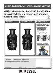
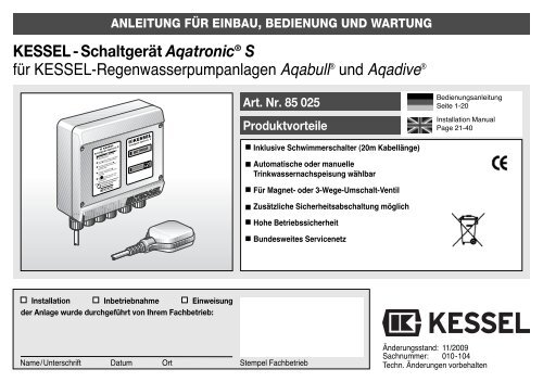
ANLEITUNG FÜR EINBAU, BEDIENUNG UND WARTUNG<br />
<strong>KESSEL</strong> - <strong>Schaltgerät</strong> Aqatronic ® S<br />
<strong>für</strong> <strong>KESSEL</strong>-Regenwasserpumpanlagen Aqabull ® und Aqadive ®<br />
Installation Inbetriebnahme Einweisung<br />
der Anlage wurde durchgeführt von Ihrem Fachbetrieb:<br />
Art. Nr. 85 025<br />
Produktvorteile<br />
Inklusive Schwimmerschalter (20m Kabellänge)<br />
Automatische oder manuelle<br />
Trinkwassernachspeisung wählbar<br />
Für Magnet- oder 3-Wege-Umschalt-Ventil<br />
Zusätzliche Sicherheitsabschaltung möglich<br />
Hohe Betriebssicherheit<br />
Bundesweites Servicenetz<br />
Name/Unterschrift Datum Ort Stempel Fachbetrieb<br />
Bedienungsanleitung<br />
Seite 1-20<br />
Installation Manual<br />
Page 21-40<br />
Änderungsstand: 11/2009<br />
Sachnummer: 010-104<br />
Techn. Änderungen vorbehalten
Inhaltsverzeichnis<br />
1. Allgemeines ........................................................................................................................ Seite 3<br />
2. Sicherheitshinweise ........................................................................................................................ Seite 4<br />
3. Technische Daten ........................................................................................................................ Seite 5<br />
4. Anlagenbeschreibung ........................................................................................................................ Seite 6<br />
4.1 Anlagenbeschreibung allgemein....................................................... Seite 7<br />
4.2 Anlagenbeschreibung Aqabull .......................................................... Seite 8<br />
4.3 Anlagenbeschreibung Aqadive ......................................................... Seite 9<br />
5. Montage 5.1 Montage <strong>Schaltgerät</strong>......................................................................... Seite 10<br />
5.2 Montage Schwimmerschalter ........................................................... Seite 11<br />
6. Elektroanschluß ........................................................................................................................ Seite 12<br />
7. Bedienung / Funktion 7.1 Inbetriebnahme................................................................................. Seite 14<br />
7.2 Normalbetrieb ................................................................................... Seite 14<br />
7.3 Manuelle Trinkwassernachspeisung................................................. Seite 14<br />
7.4 Überlaufsicherung............................................................................. Seite 15<br />
8. Inspektion und Wartung ........................................................................................................................ Seite 16<br />
9. Gewährleistung ........................................................................................................................ Seite 17<br />
10. Übergabeprotokoll ........................................................................................................................ Seite 19<br />
2
Sehr geehrter Kunde,<br />
wir freuen uns, daß Sie sich <strong>für</strong> ein Produkt<br />
von <strong>KESSEL</strong> entschieden haben.<br />
Die gesamte Anlage wurde vor Verlassen<br />
des Werkes einer strengen Qualitätskontrolle<br />
unterzogen. Prüfen Sie bitte dennoch sofort,<br />
ob die Anlage vollständig und unbeschädigt<br />
bei Ihnen angeliefert wurde. Im Falle<br />
eines Transportschadens beachten Sie<br />
bitte die Anweisung in Kapitel „Gewährleistung“<br />
dieser Anleitung.<br />
Diese Einbau-, Bedienungs- und Wartungsanleitung<br />
enthält wichtige Hinweise, die bei<br />
Montage, Bedienung, Wartung und Reparatur<br />
zu beachten sind. Vor allen Arbeiten an<br />
der Anlage müssen der Betreiber sowie das<br />
zuständige Fachpersonal diese Anleitung<br />
sorgfältig lesen und befolgen.<br />
<strong>KESSEL</strong> AG<br />
3<br />
1. Allgemeines<br />
Einsatzbereich:<br />
Das <strong>Schaltgerät</strong> AqatronicS wird zur Steuerung<br />
der <strong>KESSEL</strong>-Regenwasserpumpanlagen<br />
Aqabull und Aqadive eingesetzt.<br />
Fällt der Wasserstand in der Zisterne unter<br />
ein einstellbares Niveau erfolgt die automatische<br />
Trinkwassernachspeisung der Regenwasserpumpanlage.<br />
Die Trinkwassernachspeisung kann auch<br />
manuell aktiviert werden. Dies ist sinnvoll<br />
bei Funktionsprüfungen oder Arbeiten an<br />
der Anlage.<br />
Im Lieferumfang ist ein Schwimmerschalter<br />
enthalten. Optional kann ein zweiter<br />
Schwimmerschalter (Zubehör) <strong>für</strong> eine Sicherheitsabschaltung<br />
eingesetzt werden.
Das Personal <strong>für</strong> Montage, Bedienung, Wartung<br />
und Reparatur muss die entsprechende<br />
Qualifikation <strong>für</strong> diese Arbeiten aufweisen.<br />
Verantwortungsbereich, Zuständigkeit<br />
und die Überwachung des Personals müssen<br />
durch den Betreiber genau geregelt<br />
sein.<br />
Die Betriebssicherheit der gelieferten Anlage<br />
ist nur bei bestimmungsgemäßer Verwendung<br />
gewährleistet. Die Grenzwerte der<br />
technischen Daten dürfen auf keinen Fall<br />
überschritten werden.<br />
Diese Anlage enthält elektrische Spannungen<br />
und steuert mechanische Anlagenteile.<br />
Bei Nichtbeachtung der Einbau und Bedienungsanleitung<br />
können erheblicher Sachschaden,<br />
Körperverletzung oder gar tödliche<br />
Unfälle die Folge sein.<br />
Bei Montage, Bedienung, Wartung und Re-<br />
2. Sicherheitshinweise<br />
paratur der Anlage sind die Unfallverhütungsvorschriften,<br />
die in Frage kommenden<br />
DIN- und VDE-Normen und Richtlinien<br />
sowie die Vorschriften der örtlichen Energie<br />
Versorgungs Unternehmen zu beachten.<br />
Die Anlage stellt eine Komponete einer Gesamtanlage<br />
dar. Beachten Sie deshalb auch<br />
die Bedienungsanleitungen der Gesamtanlage<br />
und der einzelnen Komponenten. Bei<br />
jeder Montage, Wartung, Inspektion und Reparatur<br />
an einer der Komponenten ist immer<br />
die Gesamtanlage außer Betrieb zu setzen<br />
und gegen Wiedereinschalten zu sichern.<br />
Die Anlage darf nicht in explosionsgefährdeten<br />
Bereichen betrieben werden.<br />
Das <strong>Schaltgerät</strong> steht unter Spannung und<br />
darf nicht geöffnet werden. Nur Elektrofachkräfte<br />
dürfen Arbeiten an elektrischen Einrichtungen<br />
durchführen. Der Begriff Elektro-<br />
4<br />
fachkraft ist in der VDE 0105 definiert.<br />
Es ist sicherzustellen, daß sich die Elektrokabel<br />
sowie alle anderen elektrischen Anlagenteile<br />
in einem einwandfreien Zustand befinden.<br />
Bei Beschädigung darf die Anlage<br />
auf keinen Fall in Betrieb genommen werden<br />
bzw. ist umgehend abzustellen.<br />
Die Anlage hat keinen Einfluß auf die Qualität<br />
des Regenwassers.<br />
Umbau oder Veränderungen der Anlage<br />
sind nur in Absprache mit dem Hersteller zu<br />
tätigen. Originalersatzteile und vom Hersteller<br />
zugelassenes Zubehör dienen der Sicherheit.<br />
Die Verwendung anderer Teile<br />
kann die Haftung <strong>für</strong> die daraus entstehenden<br />
Folgen aufheben.
3. Technische Daten<br />
Spannung / Frequenz 230 V AC / 50 Hz<br />
Leistungsaufnahme Elektronik 5 W<br />
Schutzart IP54<br />
Schutzklasse I<br />
Temperaturbereich<br />
Schwimmerschalter<br />
0 bis 40° C<br />
Schaltleistung DC Min: 40 mA bei 8 V; Max: 60 mA bei 20 V<br />
Schaltleistung 230 V AC Min: 15 mA; Max: 100 mA<br />
Schutzklasse I Schutzleiteranschluß nach VDE 630<br />
Betriebstemperatur max. 50° C<br />
Typ Füllen (Kontakt = Öffner)<br />
Schwimmer Stellung oben: Kontakt geöffnet<br />
Schwimmer Stellung unten: Kontakt geschlossen<br />
Kabelmanteldurchmesser 9 mm<br />
Kabelmantelmaterial H07RN-F 3G1 VDE<br />
Kabellänge 20 m<br />
Veränderungen am Schwimmerschalter/Kabel nur in Absprache mit KD<br />
maximale Kabellänge 40 m, Kabelverbindung IP68 oder besser<br />
Anschluss Trinkwassernachspeisung 230 V AC / 50 HZ / max. 5 A<br />
Elektrische Anschlüsse <strong>für</strong> alle Kupferleiter geeignet 0,08 - 2,5 mm2 Kabelmanteldurchmesser 5 - 9 mm<br />
Abmessungen • Gehäuse l x b x h in mm 180 x 200 x 70<br />
• Schwimmerschalter in mm 160 x 280 x 40<br />
Gewicht • <strong>Schaltgerät</strong> Aqatronic S 710 g<br />
5
4. Anlagenbeschreibung<br />
6<br />
Gehäuse <strong>Schaltgerät</strong><br />
Zylinderschraube M4x25 (4x)<br />
Netzanschlußleitung 1 m<br />
Anschluss Trinkwassernachspeisung<br />
Anschluss Schwimmerschalter 1<br />
Anschluss Schwimmerschalter 2<br />
(Sicherheitsabschaltung optional)<br />
Kurzbedienungsanleitung<br />
LED grün Anzeige Betrieb<br />
LED orange Anzeige Trinkwassernachspeisung<br />
Taste Trinkwassernachspeisung<br />
Schwimmerschalter 1<br />
mit Anschlußleitung 20 m
4.1 Anlagenbeschreibung allgemein<br />
Das <strong>Schaltgerät</strong> Aqatronic S wird zur<br />
Steuerung der Trinkwassernachspeisung<br />
und Füllstandsüberwachung <strong>für</strong> die KES-<br />
SEL-Regenwasserpumpanlagen Aqabull<br />
und Aqadive eingesetzt.<br />
Die beiden Anlagen unterscheiden sich<br />
grundsätzlich:<br />
Aufstellungsort<br />
Pumpe<br />
Trinkwassernachspeisung<br />
erfolgt in<br />
Pumpe fördert im<br />
Normalbetrieb aus<br />
Pumpe fördert im<br />
Trinkwassernachspeisebetrieb<br />
aus<br />
Aqabull<br />
außerhalb<br />
der Zisterne<br />
Nachspeisebehälter<br />
Zisterne<br />
Nachspeisebehälter<br />
Aqadive<br />
in der<br />
Zisterne<br />
Zisterne<br />
Zisterne<br />
Zisterne<br />
4. Anlagenbeschreibung<br />
LED grün Anzeige Betrieb (8)<br />
Im Normalbetrieb leuchtet die grüne LED.<br />
Anlage ist betriebsbereit.<br />
LED orange Anzeige<br />
Trinkwassernachspeisung (9)<br />
leuchtet nicht: die Anlage befindet sich im<br />
Regenwasserbetrieb.<br />
leuchtet ständig: die Anlage befindet sich im<br />
automatischen Trinkwassernachspeisebetrieb.<br />
blinkt: die Anlage befindet sich im<br />
manuellen Trinkwassernachspeisebetrieb.<br />
Taste Trinkwassernachspeisung (10)<br />
Mit dieser Taste wird die Trinkwassernachspeisung<br />
von Hand (manuell) ein- bzw. wieder<br />
abgeschaltet.<br />
Schwimmerschalter 1 (11)<br />
Der Schwimmerschalter signalisiert dem<br />
<strong>Schaltgerät</strong> das Über- bzw. Unterschreiten<br />
des eingestellten Wasserstands in der Regenwasserzisterne.<br />
7<br />
Schwimmerschalter 2<br />
(nicht im Lieferumfang enthalten)<br />
Bei der <strong>KESSEL</strong>-Regenwasserpumpanlage<br />
Aqadive kann optional ein zweiter<br />
Schwimmerschalter installiert werden. Für<br />
den Fall, daß vergessen wird, die Trinkwassernachspeisung<br />
wieder abzuschalten oder<br />
der <strong>für</strong> die Regelung eingesetzte Schwimmerschalter<br />
defekt sein sollte, schaltet dieser<br />
Schwimmerschalter die Nachspeisung<br />
bei Erreichen des eingestellten Wasserspiegels<br />
in jedem Fall ab. Damit wird beim<br />
System Aqadive verhindert, daß unkontrolliert<br />
Trinkwasser in die Zisterne nachläuft<br />
und über den Überlauf direkt in den Abwasserkanal<br />
fließt.<br />
Beim System Aqabull ist der Einsatz eines<br />
zweiten Schwimmerschalters nicht zu empfehlen.
4.2 Anlagenbeschreibung Aqabull<br />
Dachrinne, Fallrohr<br />
Regenablauf mit Schlammeimer<br />
Regenwasserfilter<br />
3a Regenwasserfilter-Spülung<br />
3b Ventil Regenwasserfilter-Spülung<br />
Zisterne<br />
4a Einlaufberuhigung<br />
4b Überlaufsiphon<br />
4c schwimmende Entnahme<br />
Trinkwassernachspeisebehälter<br />
5a Schwimmerventil<br />
5b Absperrventil Trinkwassernachspeisung<br />
Notüberlauf mit Geruchverschluß<br />
Pumpe mit Druckschaltautomat<br />
3-Wege-Umschaltventil<br />
Trinkwassernachspeisung<br />
<strong>Schaltgerät</strong> Aqatronic S<br />
9a Schwimmerschalter 1<br />
Betriebswassernetz<br />
4. Anlagenbeschreibung<br />
<br />
<br />
<br />
5a<br />
<br />
<br />
3b<br />
5b<br />
<br />
8<br />
<br />
<br />
3a<br />
<br />
4a<br />
4b<br />
9a<br />
4c
4.3 Anlagenbeschreibung Aqadive<br />
Dachrinne, Fallrohr<br />
Regenablauf mit Schlammeimer<br />
Regenwasserfilter<br />
3a Regenwasserfilter-Spülung<br />
3b Ventil Regenwasserfilter-Spülung<br />
Zisterne<br />
4a Einlaufberuhigung<br />
4b Überlaufsiphon<br />
4c schwimmende Entnahme<br />
Pumpe<br />
Druckschaltautomat<br />
6a Absperrventil Betriebswassernetz<br />
Trinkwassernachspeisung<br />
7a Magnetventil Trinkwassernachspeisung<br />
7b Absperrventil Trinkwassernachspeisung<br />
Betriebswassernetz<br />
<strong>Schaltgerät</strong> Aqatronic S<br />
9a Schwimmerschalter 1<br />
9b Schwimmerschalter 2 (optional)<br />
4. Anlagenbeschreibung<br />
9<br />
<br />
<br />
6a<br />
7a<br />
<br />
3b<br />
7b<br />
<br />
<br />
<br />
<br />
3a<br />
4a<br />
9b<br />
9a<br />
4b<br />
<br />
4c
5.1 Montage <strong>Schaltgerät</strong><br />
Das Kapitel „Sicherheitshinweise“<br />
ist zu beachten!<br />
Bei einer <strong>KESSEL</strong>-Regenwasserpumpanlage<br />
Aqabull oder Aqadive ist das <strong>Schaltgerät</strong><br />
Bestandteil der Anlage und bereits komplett<br />
installiert. Bei einer separaten Verwendung<br />
wird das <strong>Schaltgerät</strong> an geeigneter Stelle,<br />
z.B. in Augenhöhe an der Wand montiert.<br />
Später mit max. 1 Nm wieder verschrauben<br />
(selbstschneidende Schrauben). Den Schaltkasten<br />
wie abgebildet mit den 4 Holzschrauben<br />
M3,5x30 an der Wand befestigen. Die<br />
Holzschrauben sowie Kunststoffdübel und<br />
eine Bohrschablone liegen bei.<br />
Scharnier (2x)<br />
Kunststoffdübel 5 mm (4x)<br />
Halbrund-Holzschraube 3,5x30 (4x)<br />
Deckelschrauben (4x max. 1 Nm)<br />
2<br />
5. Montage<br />
3<br />
10<br />
1<br />
1<br />
Schematische Darstellung des <strong>Schaltgerät</strong>es ohne Elektronik-Bauteile.<br />
4
5.2 Montage Schwimmerschalter:<br />
Das Kapitel „Sicherheitshinweise“<br />
ist zu beachten!<br />
Die Schwimmerschalter können in der Zisterne<br />
nach individuellen Anforderungen in der<br />
gewünschten Höhe montiert werden. Der Mindestabstand<br />
des unteren Schwimmerschalters<br />
zum Behälterboden muss ca. 15-20 cm<br />
betragen, um ein Ansaugen aus der Sedimentschicht<br />
der Zisterne zu verhindern.<br />
Bei Verwendung eines zweiten muss der Abstand<br />
zum unteren Schwimmerschalter so<br />
groß gewählt werden, daß sich beide nicht<br />
berühren können.<br />
Damit wird ein zuverlässiges Umschalten gewährleistet.<br />
Hinweis:<br />
Bei unklaren Einbauverhältnissen empfiehlt<br />
sich die Montage des Schwimmers auf einer<br />
von oben beweglichen und fixierbaren Stange.<br />
Damit kann die Position des Schwimmerschalters<br />
auch bei befüllter Zisterne leicht<br />
verändert werden.<br />
11<br />
5. Montage
Achtung!<br />
Anschluss nur durch eine Elektrofachkraft.<br />
Die einschlägigen, derzeit gültigen<br />
Vorschriften, Gesetze und Normen sind<br />
zu befolgen. Beachten Sie außerdem das<br />
Kapitel „Sicherheitshinweise“.<br />
Bei Komplettanlagen sind der Schwimmerschalter<br />
zur Steuerung der Nachspeiseeinheit<br />
sowie das Ventil bereits angeschlossen.<br />
Schließen Sie das <strong>Schaltgerät</strong> selbst an,<br />
oder soll zusätzlich der 2. Schwimmerschalter<br />
eingesetzt werden, gehen Sie bitte wie<br />
folgt vor:<br />
Am <strong>Schaltgerät</strong> werden die Dichtungen der<br />
zum Einsatz kommenden Kabel-Verschraubungen<br />
durchstoßen (siehe Abb. a).<br />
Bei den Verschraubungen, durch die keine<br />
Leitungen geführt werden, darf die<br />
Dichtung nicht durchstoßen werden, da<br />
diese zur Abdichtung des Gehäuses<br />
dient.<br />
6. Elektroanschluss<br />
Die Mutter und den Korb <strong>für</strong> die Zugentlastung<br />
auf die Leitung aufstecken (siehe<br />
Abb. b), die Leitung in das <strong>Schaltgerät</strong> einführen<br />
und entsprechend Anschlußplan anschließen.<br />
Zum Anschliessen eignet sich<br />
am besten ein kleinerer Schraubenzieher,<br />
der in die hintere Kammer der Anschlussklem-me<br />
eingeführt und niedergedrückt<br />
wird. Da-<br />
12<br />
durch öffnet sich die Klemme und die Leitung<br />
kann angeschlossen werden.<br />
Anschließend wird die Mutter mit der Hand<br />
angezogen (siehe Abb. c). Achten Sie darauf,<br />
daß der Kabelmantel bis ins Gehäuse<br />
eingeführt ist, da sonst die Abdichtung und<br />
die Zugentlastung nicht gewährleistet sind.<br />
Bitte beachten Sie:<br />
Bei Anschluss des 2. Schwimmerschalters<br />
entfernen Sie die Kurzschlußbrücke zwischen<br />
Klemme 3 und 4. Bei Betrieb ohne<br />
den 2. Schwimmerschalter muss diese<br />
Kurzschlußbrücke geschlossen sein. Sonst<br />
ist die Anlage nicht funktionsfähig.
Anschluss 3-Wege-Umschaltventil<br />
6. Elektroanschluss<br />
13<br />
Anschluss Magnetventil
7.1 Inbetriebnahme<br />
Das Kapitel „Sicherheitshinweise“<br />
ist zu beachten!<br />
Die Bedienung des <strong>Schaltgerät</strong>es ist einfach<br />
und bedarf keiner technischen Vorkenntnisse.<br />
Voraussetzung ist, Sie lesen die<br />
Einbau- und Bedienungs- und Wartungsanleitung<br />
vorher genau durch und beachten<br />
alle Anweisungen.<br />
Ist das Gerät montiert und sind alle elektrischen<br />
und mechanischen Komponenten<br />
richtig angeschlossen, kann die Inbetriebnahme<br />
erfolgen.<br />
Dazu den Netzstecker in eine Schutzkontaktsteckdose<br />
einstecken. Das Gerät befindet<br />
sich im Normalbetrieb. Die LED grün<br />
Anzeige Betrieb leuchtet.<br />
7. Bedienung / Funktion<br />
7.2 Normalbetrieb:<br />
Bei ausreichender Füllung der Regenwasserzisterne,<br />
der Wasserstand liegt über<br />
dem Niveau 1, läuft die Anlage im Regenwasserbetrieb.<br />
Im Bedarfsfall wird Betriebswasser<br />
aus der Zisterne zum Verbraucher<br />
gefördert.<br />
Sinkt der Wasserstand unter das Niveau 1<br />
wird die Trinkwassernachspeisung automatisch<br />
aktiviert. Die LED orange Anzeige<br />
Trinkwassernachspeisung leuchtet.<br />
Dieser Zustand bleibt solange erhalten, bis<br />
der Wasserstand in der Zisterne das Niveau<br />
2 überschritten hat. Die LED orange Anzeige<br />
Trinkwassernachspeisung erlischt.<br />
14<br />
7.3 Manuelle Trinkwassernachspeisung<br />
Mit der Taste „Trinkwassernachspeisung“<br />
kann die Trinkwassernachspeisung von<br />
Hand (manuell) ein- und wieder abgeschalten<br />
werden. Im eingeschalteten Zustand<br />
blinkt die LED orange Anzeige Trinkwassernachspeisung.<br />
WICHTIGER HINWEIS!<br />
Die manuelle Trinkwassernachspeisung<br />
bleibt solange aktiv, bis sie mit der Taste<br />
„Trinkwassernachspeisung“ wieder abgeschaltet<br />
wird.
7.4 Überlaufsicherung<br />
Überschreitet der Wasserstand in der Zisterne<br />
das Niveau 4, so wird eine evtl. bestehende<br />
(automatische oder manuelle) Trinkwassernachspeisung<br />
abgeschaltet und verriegelt<br />
(auch manuell nicht einschaltbar).<br />
Die Trinkwassernachspeisung läßt sich erst<br />
wieder aktivieren wenn das Niveau 3 unterschritten<br />
wurde.<br />
7. Bedienung / Funktion<br />
15
Das Kapitel „Sicherheitshinweise“<br />
ist zu beachten!<br />
Alle nachfolgend beschriebenen Inspektions-<br />
und Wartungsarbeiten dürfen nur vom<br />
autorisierten Fachpersonal durchgeführt<br />
werden.<br />
8. Inspektion und Wartung<br />
Reparaturen dürfen nur durch den Hersteller<br />
vorgenommen werden.<br />
Das <strong>Schaltgerät</strong> bedarf keiner Wartung.<br />
Der Schwimmerschalter ist in regelmäßigen<br />
Abständen auf Verschmutzung und Ausrichtung<br />
zu kontrollieren. Dabei ist auf eine scho-<br />
16<br />
nende Behandlung zu achten. Der Schwimmerschalter<br />
kann mit einer milden Seifenlauge<br />
gereinigt werden.<br />
Die Anschlussleitungen sind auf Beschädigungen<br />
zu überprüfen. Sind solche erkennbar,<br />
ist die Anlage sofort außer Betrieb zu<br />
nehmen.
1. Ist eine Lieferung oder Leistung mangelhaft,<br />
so hat <strong>KESSEL</strong> nach Ihrer Wahl den<br />
Mangel durch Nachbesserung zu beseitigen<br />
oder eine mangelfreie Sache zu liefern.<br />
Schlägt die Nachbesserung zweimal fehl oder<br />
ist sie wirtschaftlich nicht vertretbar, so hat der<br />
Käufer/Auftraggeber das Recht, vom Vertrag<br />
zurückzutreten oder seine Zahlungspflicht<br />
entsprechend zu mindern. Die Feststellung<br />
von offensichtlichen Mängeln muss unverzüglich,<br />
bei nicht erkennbaren oder verdeckten<br />
Mängeln unverzüglich nach ihrer Erkennbarkeit<br />
schriftlich mitgeteilt werden. Für Nachbesserungen<br />
und Nachlieferungen haftet<br />
<strong>KESSEL</strong> in gleichem Umfang wie <strong>für</strong> den ur-<br />
9. Gewährleistung<br />
sprünglichen Vertragsgegenstand. Für Neulieferungen<br />
beginnt die Gewährleistungsfrist<br />
neu zu laufen, jedoch nur im Umfang der Neulieferung.<br />
Es wird nur <strong>für</strong> neu hergestellte Sachen eine<br />
Gewährleistung übernommen.<br />
Die Gewährleistungsfrist beträgt 24 Monate<br />
ab Auslieferung an unseren Vertragspartner.<br />
§§ 377.378 HGB finden weiterhin Anwendung.<br />
Über die gesetzliche Regelung hinaus erhöht<br />
die <strong>KESSEL</strong> AG die Gewährleistungsfrist <strong>für</strong><br />
Leichtflüssigkeitsabscheider, Fettabscheider,<br />
Schächte, Kleinkläranlagen und Regenwasserzisternen<br />
auf 20 Jahre bezüglich Behälter.<br />
Dies bezieht sich auf die Dichtheit, Gebrauch-<br />
17<br />
stauglichkeit und statische Sicherheit.<br />
Voraussetzung hier<strong>für</strong> ist eine fachmännische<br />
Montage sowie ein bestimmungsgemäßer Betrieb<br />
entsprechend den aktuell gültigen Einbau-<br />
und Bedienungsleitungen und den gültigen<br />
Normen.<br />
2. <strong>KESSEL</strong> stellt ausdrücklich klar, dass Verschleiß<br />
kein Mangel ist. Gleiches gilt <strong>für</strong> Fehler,<br />
die aufgrund mangelhafter Wartung auftreten.<br />
Stand 10.11.2009
EG - KONFORMITÄTSERKLÄRUNG<br />
Gerät / Typ: <strong>KESSEL</strong>-<strong>Schaltgerät</strong> Aqatronic ® S<br />
Hiermit wird bestätigt, daß das oben beschriebene Produkt den wesentlichen Schutzanforderungen<br />
entspricht, welche in der Richtlinie des Rates zur Angleichung der Rechtsvorschriften der Mitgliedstaaten<br />
über die elektromagnetische Verträglichkeit (89/336/EWG) sowie in der Richtlinie des Rates zur<br />
Angleichung der Rechtsvorschriften der Mitgliedstaaten betreffend elektrische Betriebsmittel zur<br />
Verwendung innerhalb bestimmter Spannungsgrenzen (73/23/EWG) festgelegt sind.<br />
Zur Beurteilung der Erzeugnisse hinsichtlich der elektromagnetischen Verträglichkeit<br />
wurden folgende Normen herangezogen:<br />
EN 55014<br />
EN 55104<br />
Zur Beurteilung der Erzeugnisse hinsichtlich der elektrischen Sicherheit<br />
wurden folgende Normen herangezogen:<br />
DIN EN 60730-1:1996-01<br />
Kessel AG, Bahnhofstraße 31, 85101 Lenting<br />
B. Kessel A. Kessel<br />
Lenting 10.11.2009<br />
18
Typenbezeichnung *<br />
<strong>KESSEL</strong>-Bestellnummer *<br />
Fertigungsdatum *<br />
(* gemäß Typenschild/Rechnung)<br />
Objektbezeichung / Anlagenbetreiber<br />
Adresse / Telefon / Telefax<br />
Planer / Adresse / Telefon / Telefax<br />
Ausführende Installationsfirma<br />
Adresse / Telefon / Telefax<br />
Ausführende Elektrofirma<br />
Adresse / Telefon / Telefax<br />
Abnahmeberechtigter<br />
Adresse / Telefon / Telefax<br />
Übergabeperson<br />
Sonstige Anmerkungen<br />
10. Übergabeprotokoll<br />
Die Inbetriebnahme laut EBA und Einweisung wurde im Beisein des Abnahmeberechtigten und des Anlagenbetreibers durchgeführt.<br />
______________________________ ______________________________ _________________________<br />
Ort, Datum Unterschrift Abnahmeberechtigter Unterschrift Anlagenbetreiber<br />
19
✂<br />
■<br />
■<br />
■<br />
Übergabeprotokoll<br />
20
INSTALLATION, OPERATION AND MAINTENANCE INSTRUCTIONS<br />
<strong>KESSEL</strong> - Switch Unit Aqatronic ® S<br />
for <strong>KESSEL</strong> rainwater pumping systems Aqabull ® and Aqadive ®<br />
Installation Service<br />
of this unit should be carried out by a licensed professsional<br />
servicer:<br />
Company / Telephone number<br />
Art. # 85 025<br />
Product Advantages<br />
Including floating switch (20 m cable length)<br />
Automatic or manual drinking water feeding can be selected<br />
For solenoid or 3-way switch-over valve<br />
Additional safety switch-off possible<br />
High operational security<br />
Nationwide service network<br />
Edition: 11/2009<br />
Number: 010-104<br />
Subject to technical amendments
Table of content<br />
1. General ........................................................................................................................ Page 23<br />
2. Safety Instructions ........................................................................................................................ Page 24<br />
3. Technical data ........................................................................................................................ Page 25<br />
4. System description ........................................................................................................................ Page 26<br />
4.1 General system description .............................................................. Page 27<br />
4.2 System description Aqabull............................................................... Page 28<br />
4.3 System description Aqadive.............................................................. Page 29<br />
5. Installation 5.1 Installation of the switch unit ............................................................. Page 30<br />
5.2 Installation of the floating switches ................................................... Page 31<br />
6. Electrical Connection ........................................................................................................................ Page 32<br />
7. Operation 7.1 Initial operation ................................................................................. Page 34<br />
7.2 Normal mode .................................................................................... Page 34<br />
7.3 Manual drinking water feeding .......................................................... Page 34<br />
7.4 Overflow protection........................................................................... Page 35<br />
8. Inspection and Maintenance ........................................................................................................................ Page 36<br />
9. Guarantee ........................................................................................................................ Page 37<br />
10. Handover Certificate ........................................................................................................................ Page 39<br />
22
Dear customer,<br />
we are pleased that you have decided to buy<br />
a <strong>KESSEL</strong> product.<br />
The entire plant was subjected to a stringent<br />
quality control before it left our factory. Nevertheless,<br />
please check immediately<br />
whether the plant has been delivered to you<br />
complete and undamaged. In case of any<br />
transport damage, please refer to the instructions<br />
in the chapter “Warranty” in this<br />
manual.<br />
These installation, operating and maintenance<br />
instructions contain important information<br />
that has to be observed during assembly,<br />
operation, maintenance and repair. Prior<br />
to carrying out any work on the plant, the<br />
operator and the responsible technical personnel<br />
must carefully read and heed these<br />
instructions.<br />
<strong>KESSEL</strong> AG<br />
23<br />
1. General<br />
Area of application:<br />
The switch unit Aqatronic S is used to control<br />
the <strong>KESSEL</strong> rainwater pumping systems Aqabull<br />
and Aqadive.<br />
If the water level in the cistern falls below a certain<br />
adjustable level, automatic drinking water<br />
feeding of the rainwater pumping system is<br />
triggered<br />
Drinking water feeding can also be activated<br />
manually. This is useful when functional<br />
tests or work are being carried out on the<br />
plant.<br />
A floating switch is included in the scope of<br />
supply. Optionally, a second floating switch<br />
(accessories) can be used for safety switchoff.
The personnel for assembly, operation,<br />
maintenance and repair must possess the<br />
appropriate qualification for this type of<br />
work. The area of responsibility, the authority<br />
and the supervision of personnel must be<br />
exactly regulated by the operator.<br />
The operational security of the plant supplied<br />
is only guaranteed when it is used in<br />
accordance with the regulations. The limits<br />
of the technical specifications may not be<br />
exceeded on any account.<br />
This plant contains electric charges and controls<br />
mechanical plant components. Noncompliance<br />
with the installation and operating<br />
instructions may result in considerable<br />
damage to property, personal injuries or<br />
even fatal accidents.<br />
During assembly, operation, maintenance<br />
and repair of the plant, the regulations for the<br />
prevention of accidents, the pertinent DIN<br />
and VDE standards and directives, as well<br />
2. Safety Instructions<br />
as the directives of the local power supply industry<br />
must be heeded.<br />
The system represents one component in a<br />
whole plant. Please therefore also heed the<br />
operating instructions for plant as a whole<br />
and the individual components. During assembly,<br />
maintenance, service and repair<br />
work on one of the components, the plant as<br />
a whole must always be put out of operation<br />
and secured against unintentional restart.<br />
The plant must not be operated in potentially<br />
explosive areas.<br />
The switch unit is live and must not be opened.<br />
Only qualified electricians may carry<br />
out work on electrical facilities. The term<br />
qualified electrician is defined in VDE 0105.<br />
It must be ensured that the electric cables as<br />
well as all other electrical plant components<br />
are in a faultless condition. In case of da-<br />
24<br />
mage, the plant may on no account be put<br />
into operation or must be stopped immediately.<br />
The plant does not influence the quality of<br />
the rainwater.<br />
Conversions or changes to the plant may<br />
only be carried out in agreement with the<br />
manufacturer. For safety reasons, use original<br />
spare parts and accessories approved<br />
by the manufacturer. The use of other parts<br />
may void the liability for any consequences<br />
arising thereof.
3. Technical Data<br />
Voltage / Frequency 230 V AC / 50 Hz<br />
Power consumption electronics 5 W<br />
Protective rating IP54<br />
Protective class I<br />
Temperature range<br />
Floating switch<br />
0 to 40° C<br />
Switching capacity DC Min: 40 mA at 8 V; Max: 60 mA at 20 V<br />
Switching capacity 230 V AC Min: 15 mA; Max: 100 mA<br />
Protective class I Earth conductor acc. to VDE 630<br />
Operating temperature max. 50° C<br />
Type Fill (contact = break contact)<br />
Float position top: Contact broken<br />
Float position bottom: Contact made<br />
Cable sheath diameter 9 mm<br />
Cable sheath material H07RN-F 3G1 VDE<br />
Cable length 20 m<br />
Changes to the floating switch/cable only in agreement with Customer Services<br />
Maximum cable length 40 m, cable connection IP68 or better<br />
Connection for drinking water feeding 230 V AC / 50 Hz / max. 5 A<br />
Electrical connections suitable for all copper conductors 0.08 - 2.5 mm2<br />
Cable sheath diameter<br />
Dimensions<br />
5 - 9 mm<br />
• Housing l x w x h in mm 180 x 200 x 70<br />
• Floating switch in mm 160 x 280 x 40<br />
Weight • Switch unit Aqatronic S 710 g<br />
25
4. System description<br />
26<br />
Switch unit housing<br />
Cylinder head screw M4x25 (4x)<br />
Mains connection cable 1 m<br />
Connection drinking water feeding<br />
Connection floating switch 1<br />
Connection floating switch 2<br />
(optional safety switch-off)<br />
Brief operating instructions<br />
LED green for operation<br />
LED orange for drinking water feeding<br />
Button for drinking water feeding<br />
Floating switch 1<br />
with connection cable 20 m
4.1 General system description<br />
The switch unit Aqatronic S is used to control<br />
drinking water feeding and filling level monitoring<br />
for the <strong>KESSEL</strong> rainwater pumping systems<br />
Aqabull and Aqadive.<br />
There are basic differences between the two<br />
systems:<br />
Installation location<br />
pump<br />
Drinking water<br />
feeding takes<br />
place in<br />
In normal mode,<br />
pump pumps from<br />
In drinking water<br />
feeding mode,<br />
pump pumps from<br />
Aqabull<br />
outside the<br />
cistern<br />
feeding tank<br />
feeding tank<br />
Aqadive<br />
in the<br />
cistern<br />
cistern<br />
cistern<br />
cistern<br />
4. System description<br />
LED green for operation (8)<br />
During normal mode the green LED is lit.<br />
Plant is ready for operation.<br />
LED orange<br />
for drinking water feeding (9)<br />
Is not lit: The plant is in rainwater<br />
mode.<br />
Constantly lit: The plant is in automatic<br />
drinking water feeding<br />
mode.<br />
Is flashing: The plant is in manual<br />
drinking water feeding<br />
mode.<br />
Button for drinking water feeding (10)<br />
This button is used to switch the manual<br />
drinking water feeding on and off again.<br />
Floating switch 1 (11)<br />
The floating switch indicates to the switch<br />
unit whether the set water level in the rainwater<br />
cistern is exceeded or not reached.<br />
27<br />
Floating switch 2<br />
(not included in the scope of supply)<br />
In the case of the <strong>KESSEL</strong> rainwater pumping<br />
system Aqadive, a second floating<br />
switch can be installed as an option. In case<br />
the operator forgets to switch the drinking<br />
water feeding function off again or the floating<br />
switch used for control purposes is faulty,<br />
this floating switch always switches the<br />
feeding function off whenever the set water<br />
level is reached. This means that with the<br />
Aqadive system, this second switch prevents<br />
drinking water being fed into the cistern<br />
uncontrolled and flowing into the sewage<br />
channel via the overflow.<br />
The use of a second floating switch is not recommended<br />
with the Aqabull system.
4.2 System description Aqabull<br />
Gutter, drainpipe<br />
Drain with sludge bucket<br />
3 Rainwater filter<br />
3a Rainwater filter rinsing<br />
3b Valve for rainwater filter rinsing<br />
Cistern<br />
4a Feed slowdown<br />
4b Overflow siphon<br />
4c Floating removal<br />
Drinking water feeding tank<br />
5a Floating switch<br />
5b Shut-off valve for drinking water feeding<br />
Emergency overflow with odour trap<br />
Pump with automatic pressure switch<br />
3-way switch-over valve<br />
Drinking water feeding<br />
Switch unit Aqatronic S<br />
9a Floating switch 1<br />
Service water network<br />
4. System description<br />
<br />
<br />
<br />
5a<br />
<br />
<br />
3b<br />
5b<br />
<br />
28<br />
<br />
<br />
<br />
3a<br />
4a<br />
4b<br />
9a<br />
4c
4.3 System description Aqadive<br />
Gutter, drainpipe<br />
Drain with sludge bucket<br />
Rainwater filter<br />
3a Rainwater filter rinsing<br />
3b Valve for rainwater filter rinsing<br />
Cistern<br />
4a Feed slowdown<br />
4b Overflow siphon<br />
4c Floating removal<br />
Pump<br />
Automatic pressure switch<br />
6a Shut-off valve service water network<br />
Drinking water feeding<br />
7a Solenoid drinking water feeding<br />
7b Shut-off valve drinking water feeding<br />
Service water network<br />
Switch unit Aqatronic S<br />
9a Floating switch 1<br />
9b Floating switch 2 (optional)<br />
4. System description<br />
29<br />
<br />
<br />
6a<br />
7a<br />
<br />
3b<br />
7b<br />
<br />
<br />
<br />
<br />
3a<br />
4a<br />
9b<br />
4b<br />
9a<br />
<br />
4c
5.1 Installation of the switch unit<br />
The chapter “Safety instructions” must be heeded!<br />
The switch unit is part of the <strong>KESSEL</strong> rainwater<br />
pumping system Aqabull or Aqadive and is already<br />
completely installed in the system. If used<br />
separately, the switch unit is installed in a suitable<br />
spot, e.g. at eye level on the wall. Screw<br />
in place (self-cutting screws) later using max. 1<br />
Nm. Attach the switch box to the wall as shown<br />
using the 4 wood screws M3.5x30. The wood<br />
screws, plastic dowels and a drilling template<br />
are included.<br />
Hinge (2x)<br />
Plastic dowel 5 mm (4x)<br />
Slotted head wood screw 3.5x30 (4x)<br />
Cover screws (4x max. 1 Nm)<br />
2<br />
5. Installation<br />
3<br />
30<br />
1<br />
1<br />
4
5.2 Installation of the floating switches<br />
The chapter “Safety instructions” must<br />
be heeded!<br />
The floating switches can be mounted in the cistern<br />
at the desired height according to individual<br />
requirements. The minimum distance from<br />
the lower floating switch to the floor of the tank<br />
must be about 15-20 cm in order to prevent sediment<br />
being suctioned in from the bottom of<br />
the cistern.<br />
When a second floating switch is used, the distance<br />
to the lower floating switch must be big<br />
enough to prevent the two touching.<br />
This guarantees reliable switch-over.<br />
Note:<br />
If the installation conditions are not clear, we recommend<br />
mounting the floating switch on a<br />
pole that can be fixed in place and is movable<br />
from above. This allows the position of the floating<br />
switch to be changed slightly even if the cistern<br />
is full.<br />
31<br />
5. Installation
Caution!<br />
Connection may only be carried out by a<br />
qualified electrician. The relevant currently<br />
valid directives, laws and standards<br />
must be observed. Please heed<br />
the chapter “Safety instructions” as<br />
well.<br />
In the case of complete plants, the floating<br />
switch for controlling the feeding unit and the<br />
valve are already connected.<br />
If you are connecting the switch unit yourself,<br />
or the second floating switch is to be used in<br />
addition, please proceed as follows:<br />
Pierce the seals of the cable screw connections<br />
to be used on the switch unit (see Fig. a).<br />
In the case of those screw connections<br />
where no cables are to be routed, the<br />
seal must not be pierced since they are<br />
required to seal the housing.<br />
6. Electrical Connection<br />
Insert the nut and the cage for strain relief<br />
onto the cable (see Fig. b), insert the cable<br />
into the switch unit and connect up according<br />
to the circuit diagram. A smaller screwdriver<br />
is most suitable for connection, this<br />
should be inserted into the rear chamber of<br />
the connection terminal and pushed down-<br />
32<br />
wards. This opens the terminal and the<br />
cable can be connected.<br />
Then the nut is tightened by hand (see Fig.<br />
c). Make sure that the cable sheath is inserted<br />
right into the housing as otherwise the<br />
seal and strain relief are not guaranteed.<br />
Please note:<br />
When connecting the 2nd floating switch,<br />
remove the short-circuit jumper between<br />
terminal 3 and 4. For operation without the<br />
2nd floating switch, this short-circuit jumper<br />
has to be closed. Otherwise the system is<br />
not functional.
6. Electrical Connection<br />
Anschluss 3-Wege-Umschaltventil<br />
33<br />
Anschluss Magnetventil
7.1 Initial operation<br />
The chapter “Safety instructions” must be<br />
heeded!<br />
The switch unit is easy to use and does not require<br />
any technical knowledge. However, you<br />
are required to read the installation, operating<br />
and maintenance instructions through carefully<br />
prior to use and heed all the instructions.<br />
Once the unit has been mounted and all the electrical<br />
and mechanical components have<br />
been connected up correctly, it can be put into<br />
operation.<br />
To do this, insert the mains plug into a safety<br />
socket. The unit is in normal mode. The green<br />
LED lights up to show operation.<br />
7. Operation<br />
7.2 Normal mode:<br />
If the rainwater cistern is full enough, with the<br />
water level above level 1, the system runs in<br />
rainwater mode. When required, service water<br />
is pumped from the cistern to the consumer.<br />
If the water level drops to below level 1, drinking<br />
water feeding is activated automatically.<br />
The orange LED lights up to show drinking<br />
water feeding.<br />
This state remains until the water level in the<br />
cistern has risen to above level 2. The orange<br />
LED for drinking water feeding goes out.<br />
34<br />
7.3 Manual drinking water feeding<br />
The button “drinking water feeding” can be<br />
pressed to switch drinking water feeding on<br />
and off manually. When switched on, the orange<br />
LED flashes, showing drinking water feeding.<br />
Important note!<br />
Manual drinking water feeding remains active<br />
until it is switched off by the button<br />
“drinking water feeding” being pressed<br />
again.
7.4 Overflow protection<br />
If the water level in the cistern rises above level 4,<br />
any (automatic or manual) drinking water<br />
feeding is switched off and locked (cannot be switched<br />
on manually either).<br />
Drinking water feeding can only be activated<br />
again when the water has fallen to below level 3.<br />
35<br />
7. Operation
The chapter “Safety instructions” must<br />
be heeded!<br />
All the servicing and maintenance work described<br />
below may only be carried out by authorised<br />
qualified personnel.<br />
Repairs may only be carried out by the manufacturer.<br />
8. Instruction and Maintenance<br />
The switch unit does not require any maintenance.<br />
The floating switch must be checked for soiling<br />
and alignment at regular intervals. It must always<br />
be handled carefully. The floating switch<br />
can be cleaned using a mild soap solution.<br />
The connection cables must be checked for<br />
36<br />
damage. If any damage can be detected, the<br />
plant must be put out of operation immediately.
1. In the case that a <strong>KESSEL</strong> product is defective,<br />
<strong>KESSEL</strong> has the option of repairing<br />
or replacing the product. If the product remains<br />
defective after the second attempt to<br />
repair or replace the product or it is economically<br />
unfeasible to repair or replace the<br />
product, the customer has the right to cancel<br />
the order / contract or reduce payment<br />
accordingly. <strong>KESSEL</strong> must be notified immediately<br />
in writing of defects in a product.<br />
In the case that the defect is not visible or<br />
difficult to detect, <strong>KESSEL</strong> must be notified<br />
immediately in writing of the defect as soon<br />
as it is discovered. If the product is repaired<br />
or replaced, the newly repaired or replaced<br />
product shall receive a new warranty identical<br />
to that which the original (defective)<br />
product was granted. The term defective<br />
9. Guarantee<br />
product refers only to the product or part<br />
needing repair or replacement and not necessarily<br />
to the entire product or unit. KES-<br />
SEL products are warranted for a period of<br />
24 month. This warranty period begins on<br />
the day the product is shipped form KES-<br />
SEL to its customer. The warranty only applies<br />
to newly manufactured products. Additional<br />
information can be found in section<br />
377 and 378 of the HGB.<br />
In addition to the standard warranty, KES-<br />
SEL offers an additional 20 year warranty<br />
on the polymer bodies of class I / II fuel separators,<br />
grease separators, inspection<br />
chambers, wastewater treatment systems<br />
and rainwater storage tanks.<br />
This additional warranty applies to the wa-<br />
37<br />
tertightness, usability and structural soundness<br />
of the product.<br />
A requirement of this additional warranty is<br />
that the product is properly installed and<br />
operated in accordance with the valid installation<br />
and user's manual as well as the<br />
corresponding norms / regulations.<br />
2. Wear and tear on a product will not be considered<br />
a defect. Problems with products<br />
resulting from improper installation, handling<br />
or maintenance will also be considered<br />
a defect.
EC DECLARATION OF CONFORMITY<br />
Electromagnetism Guidelines 89/336/EEC Electromagnetism Guidelines 89/336/EEC<br />
Low Voltage Guidelines 73/23/EEC<br />
Kessel AG, D-85101 Lenting<br />
we declare that the product<br />
Type: <strong>KESSEL</strong>-Control unit Aqatronic ® S<br />
is in agreement with<br />
EN 55014<br />
EN 55104<br />
DIN EN 60730-1:1996-0<br />
Lenting 10.07.2006<br />
B. Kessel A. Kessel<br />
38
Type designation*<br />
<strong>KESSEL</strong> order number *<br />
Production date *<br />
(* according to rating plate/invoice)<br />
Product name / system owner/operator<br />
Address / Phone / Fax<br />
Designer / Address / Phone / Fax<br />
Installation firm<br />
Address / Phone / Fax<br />
Electrical firm<br />
Address / Phone / Fax<br />
Authorised acceptance representative<br />
Address / Phone / Fax<br />
Person handing over<br />
Other comments<br />
10. Handover Certificate<br />
The putting into service according to the EBA and instruction was carried out in the presence of the authorised acceptance representative<br />
and the system owner/operator.<br />
______________________________ ______________________________ _________________________<br />
Town/City, Date Signature of authorised acceptance representative Signature of system owner/operator<br />
39
A l l e s f ü r d i e E n t w ä s s e r u n g<br />
❑<br />
❑<br />
❑<br />
❑<br />
❑<br />
❑<br />
Rückstauverschlüsse<br />
Hebeanlagen<br />
Abläufe / Rinnen<br />
innerhalb von Gebäuden<br />
Abläufe<br />
außerhalb von Gebäuden<br />
Abscheider<br />
Fettabscheider<br />
Öl-/Benzinabscheider<br />
Stärkeabscheider<br />
Sinkstoffabscheider<br />
Kleinkläranlagen<br />
Schächte<br />
Regenwassernutzanlagen