Acoustimass® 16 Series II Acoustimass® 15 Series III - Bose
Acoustimass® 16 Series II Acoustimass® 15 Series III - Bose
Acoustimass® 16 Series II Acoustimass® 15 Series III - Bose

Create successful ePaper yourself
Turn your PDF publications into a flip-book with our unique Google optimized e-Paper software.
English Español Français<br />
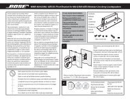
Figure 6<br />
System input cable<br />
connectors<br />
Figure 7<br />
Unzipping the paired wires<br />
SETTING UP<br />
Connecting the Acoustimass ® module to the receiver<br />
The system input cable is 20 feet (6.1 meter) long and connects the Acoustimass module to<br />
your surround sound receiver. Unlike the speaker cables, this input cable has a multi-pin !<br />
connector that inserts into the Audio Input jack on the module (Figure 6).<br />
Module input jack<br />
System input<br />
cable connector<br />
At the other end of the system input cable, multiple wire pairs that “unzip” for easy reach and<br />
insertion into terminals on your receiver (Figure 7). A red collar marks a wire as positive (+).<br />
CAUTION: Do NOT connect your module to the TV, which lacks the required amplification.<br />
The single RCA connector at that end is for use ONLY with a receiver that handles !<br />
low-frequency effects and provides an LFE/SUBWOOFER jack (Figure 7).<br />
RCA<br />
connector<br />
for LFE<br />
only<br />
Wire pair<br />
CAUTION: Before making these connections, turn off your receiver to prevent unwanted noises<br />
when you plug the Acoustimass ® module into it.<br />
To make the connections (Figure 8 on page 10):<br />
1. Insert the multi-pin connector on the system input cable into the input jack on the !<br />
Acoustimass module. Tighten the two thumbscrews to secure the connection.<br />
2. Connect each wire pair on the other end of the system input cable to your surround<br />
receiver, which should have audio output terminals labeled:<br />
• Right, Left, Center for the front audio channels<br />
• Right Surround, Left Surround, and possibly Center Surround for the rear channels. !<br />
The specific labels on your receiver may differ slightly.<br />
CAUTION: Do not allow exposed wires to brush against each other; this could damage your<br />
receiver.<br />
3. Carefully match the polarity of the connections (+ to + and – to –).<br />
• Attach each red-collared wire (+) to the appropriate + terminal.<br />
• Attach each plain wire (–) to the appropriate – terminal.<br />
4. If applicable to your receiver, insert the RCA plug marked LFE on the system input cable<br />
into the LFE/SUBWOOFER OUT jack on your surround receiver. Remove the cover first.<br />
9