Istruzioni di montaggio
Istruzioni di montaggio
Istruzioni di montaggio

Create successful ePaper yourself
Turn your PDF publications into a flip-book with our unique Google optimized e-Paper software.
ITALIANO<br />
ENGLISH<br />
FRANÇAIS<br />
DEUTSCH<br />
ESPAÑOL<br />
6<br />
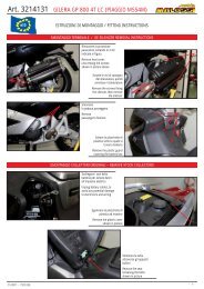
ISTRUZIONI Dl MONTAGGIO (scooter e ciclomotori)<br />
1) Pulire accuratamente la zona esterna del carter lato trasmissione su cui si andrà ad operare.<br />
2) Smontare il carter lato trasmissione avendo cura <strong>di</strong> non danneggiare o perdere le bussole <strong>di</strong> centraggio e le viti dello stesso (Foto 1a).<br />
3) Svitare il dado <strong>di</strong> bloccaggio del variatore sull’albero motore (Foto 1b).<br />
4) Togliere completamente tutto il gruppo variatore originale sfi landolo dall’albero motore (Foto 2).<br />
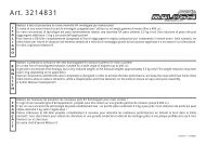
5) Smontare il gruppo frizione posteriore nei kit ove sia prevista la molla in sostituzione dell’originale (Foto 3a - 3b).<br />
6) Per montare l’eventuale molla presente nel kit Malossi bisogna svitare il dado <strong>di</strong> serraggio della fl angia porta ceppi (Foto 4a - 4b) facendo attenzione alla spinta della molla.<br />
7) Montare la nuova molla fornita nel kit (Foto 5).<br />
8) Ricomporre il gruppo frizione come in precedenza (Foto 6). Controllare lo stato <strong>di</strong> usura della vostra cinghia; qualora non risultasse perfetta vi consigliamo <strong>di</strong> sostituirla con una delle nostre cinghie Malossi Special Belt o Kevlar Belt.<br />
Rimontare il gruppo frizione con la cinghia inserita nella puleggia e serrare il dado <strong>di</strong> bloccaggio (Foto 7).<br />
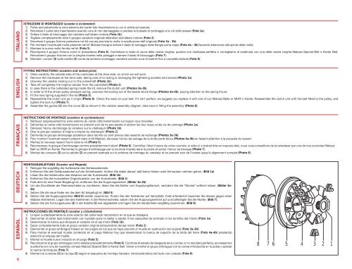
9) Montare i cursori (3) sulla calotta (2) come da schema <strong>montaggio</strong> variatore avendo cura <strong>di</strong> inserirli fi no a completa battuta (Foto 8).<br />
FITTING INSTRUCTIONS (scooters and motorcycles)<br />
1) Clean carefully the outside area of the crankcase at the drive side, on which we will work.<br />
2) Remove the crankcase at the drive side, taking care of no losing or damaging the tightening sockets and screws (Photo 1a).<br />
3) Unscrew the variator locking nut on the crankshaft (Photo 1b).<br />
4) Take off completely the original variator from the crankshaft (Photo 2).<br />
5) In case there is the calibrated spring inside the kit, remove the clutch unit (Photos 3a-3b).<br />
6) In order to fi t the driven pulley pressure spring, unscrew the locking nut of the bearer-block fl ange (Photos 4a-4b), paying attention to the spring thrust.<br />
7) Fit the new spring supplied in the kit (Photo 5).<br />
8) Reassemble the clutch unit as in origin (Photo 6). Check the wear on your belt; if it isn’t perfect, we suggest you replace it with one of our Malossi Belts or MHR in Kevlar. Reassemble the clutch unit with the belt fi tted to the pulley, and<br />
tighten the lock nut (Photo 7).<br />
9) Assemble the guides (3) into the cover (2) as shown in the variator assembly <strong>di</strong>agram, take care in fi tting the assembly (Photo 8).<br />
INSTRUCTIONS DE MONTAGE (scooters et cyclomoteurs)<br />
1) Nettoyez soigneusement la zone externe du carter côté transmission sur lequel vous travaillez.<br />
2) Démontez le carter côté transmission en prenant soin de ne pas perdre ni abimer les four reaux et les vis de centrage (Photo 1a).<br />
3) Dévissez l’écrou de blocage du variateur sur le vilebrequin (Photo 1b).<br />
4) Otez le groupe variateur d’origine complet du vilebrequin (Photo 2).<br />
5) Démontez le groupe embrayage postérieur dans les kits ou sont prévus des ressorts de rechange (Photos 3a-3b).<br />
6) Pour monter l’éventuel ressort présent dans le kit Malossi, dévissez l’écrou de serrage de la bride porte-blocs (Photos 4a-4b) en faisant attention à la poussée du ressort.<br />
7) Montez le nouveau ressort fourni dans le kit (Photo 5).<br />
8) Recomposez le groupe d’embrayage comme précédemment décrit (Photo 6). Contrôlez l’état d’usure de votre courroie; si celle-ci s’avérait être en mauvais état, nous vous conseillons de la remplacer par une de nos courroies Malossi<br />
Belt ou MHR en Kevlar. Remontez le groupe d’embrayage par la courroie insérée dans la poulie et serrez l’écrou de blocage (Photo 7).<br />
9) Montez les curseurs (3) sur la calotte (2) en prenant exemple sur le schéma de montage du variateur et en prenant soin de l’insérer jusqu’à alignement complet (Photo 8).<br />
MONTAGEANLEITUNG (Scooter und Mopeds)<br />
1) Reinigen Sie sorgfältig <strong>di</strong>e Außenseite des Gehäusedeckels.<br />
2) Entfernen Sie den Gehäusedeckel auf der Antriebsseite. Achten Sie dabei darauf, daß keine Hulsen oder Schrauben verloren gehen. (Bild 1a)<br />
3) Lösen Sie <strong>di</strong>e Haltemutter des Variators auf der Kurbelwelle. (Bild 1b)<br />
4) Entfernen Sie den kompletten Originalvariator von der Kurbelwelle. (Bild 2)<br />
5) Falls dem kit eine Feder Beigefugt ist, entfernen Sie <strong>di</strong>e Kupplungseinheit. (Bilder 3a-3b)<br />
6) Um <strong>di</strong>e Druckfeder der Riemenscheibe zu montierern, lösen Sie <strong>di</strong>e Mutter vom Kupplungsfl ansch, nachdem Sie <strong>di</strong>e “Glocke” entfernt haben. (Bilder 4a-<br />
4b)<br />
7) Setzen Sie <strong>di</strong>e neue Feder ein <strong>di</strong>e dem Kit beigefugt ist. (Bild 5)<br />
8) Setzen Sie <strong>di</strong>e Kupplungseinheit (Bild 6) wieder zusammen. Prufen Sie den Keilriemen auf Verschleiß. Falls erforderlich tauschen Sie <strong>di</strong>esen gegen einen<br />
Malossi Keilriemen. Legen Sie den Keilriemen in <strong>di</strong>e Riemenscheibe, setzen Sie <strong>di</strong>e Kupplungseinheit auf und befestigen Sie <strong>di</strong>e Mutter. (Bild 7).<br />
9) Setzen Sie <strong>di</strong>e Fuhrungsstucke (3) in <strong>di</strong>e Kalotte (2) wie abgebildet und fugen Sie <strong>di</strong>e Variatorteile sorgfältig zusammen. (Bild 8)<br />
INSTRUCCIONES DE MONTAJE (scooter y ciclomotores)<br />
1) Limpiar cuidadosamente la zona exterior del cárter lado transmisión en la que se trabajará.<br />
2) Desmontar el cárter lado transmisión con cuidado para no dañar o perder ni los casquillos de centrado ni los tornillos del mismo (Foto 1a).<br />
3) Desenroscar la tuerca que bloquea el variador en el eje motor (Foto 1b).<br />
4) Sacar completamente todo el grupo variador original extrayéndolo del eje motor (Foto 2).<br />
5) Desmontar el grupo embrague trasero en los juegos en los que se haya previsto el muelle en sustitución del original (Foto 3a-3b).<br />
6) Para montar el eventual muelle contenido en el juego Malossi hay que desenroscar la tuerca de sujeción de la brida del freno (Foto 4a-4b) prestando<br />
atención al empuje del muelle.<br />
7) Montar el muelle nuevo incluido en el juego (Foto 5).<br />
8) Recomponer el grupo embrague como estaba precedentemente (Foto 6). Controlar el estado de desgaste de su correa; si no resultara perfecta, aconsejamos<br />
sustituirla con una de nuestras correas Malossi Special Belt o Kevlar Belt. Volver a montar el grupo embrague con la correa introducida en la polea y apretar<br />
la tuerca de bloqueo (Foto 7).<br />
9) Montar los cursores (3) en la caja (2) según el esquema de montaje Variador, introduciéndolos del todo con cuidado (Foto 8).<br />
8 7 6 5 4 3 2 1