introduction - Bose
introduction - Bose
introduction - Bose

Create successful ePaper yourself
Turn your PDF publications into a flip-book with our unique Google optimized e-Paper software.
SETUP<br />
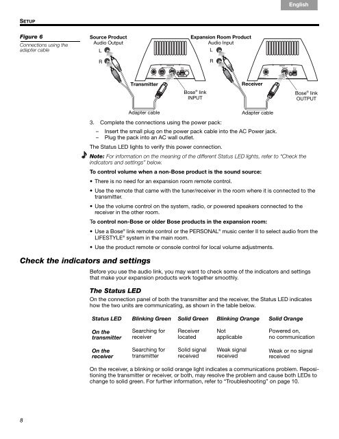
Figure 6<br />
Connections using the<br />
adapter cable<br />
8<br />
Source Product<br />
Audio Output<br />
L<br />
<br />
R<br />
<br />
Français Español<br />
Expansion Room Product<br />
Audio Input<br />
L<br />
<br />
R<br />
Transmitter Receiver<br />
Adapter cable<br />
Check the indicators and settings<br />
<strong>Bose</strong> ® link<br />
INPUT<br />
Adapter cable<br />
English<br />
<strong>Bose</strong> ® link<br />
OUTPUT<br />
3. Complete the connections using the power pack:<br />
– Insert the small plug on the power pack cable into the AC Power jack.<br />
– Plug the pack into an AC wall outlet.<br />
The Status LED lights to verify this power connection.<br />
Note: For information on the meaning of the different Status LED lights, refer to “Check the<br />
indicators and settings” below.<br />
To control volume when a non-<strong>Bose</strong> product is the sound source:<br />
• There is no need for an expansion room remote control.<br />
• Use the remote that came with the tuner/receiver in the room where it is connected to the<br />
transmitter.<br />
• Use the volume control on the system, radio, or powered speakers connected to the<br />
receiver in the other room.<br />
To control non-<strong>Bose</strong> or older <strong>Bose</strong> products in the expansion room:<br />
• Use a <strong>Bose</strong> ® link remote control or the PERSONAL ® music center II to select audio from the<br />
LIFESTYLE ® system in the main room.<br />
• Use the product remote or console control for local volume adjustments.<br />
Before you use the audio link, you may want to check some of the indicators and settings<br />
that make your expansion products work together smoothly.<br />
The Status LED<br />
On the connection panel of both the transmitter and the receiver, the Status LED indicates<br />
how the two units are communicating, as shown in the table below.<br />
Status LED Blinking Green Solid Green Blinking Orange Solid Orange<br />
On the<br />
transmitter<br />
On the<br />
receiver<br />
Searching for<br />
receiver<br />
Searching for<br />
transmitter<br />
Receiver<br />
located<br />
Solid signal<br />
received<br />
Not <br />
applicable<br />
Weak signal<br />
received<br />
Powered on, <br />
no communication<br />
Weak or no signal<br />
received<br />
On the receiver, a blinking or solid orange light indicates a communications problem. Repositioning<br />
the transmitter or receiver, or both, may resolve the problem and cause both LEDs to<br />
change to solid green. For further information, refer to “Troubleshooting” on page 10.