

2876 Manual Page - Victor Technologies
2876 Manual Page - Victor Technologies
2876 Manual Page - Victor Technologies

You also want an ePaper? Increase the reach of your titles
YUMPU automatically turns print PDFs into web optimized ePapers that Google loves.
82 Benning Street, West Lebanon, NH 03784 USA<br />
(603) 298-5711 • www.thermal-dynamics.com<br />
General Information<br />
This kit allows any RPT Torch Adapter Kit to be interfaced<br />
with a Remote Pendant Control. The kit can be<br />
used with any Mechanized Torch System with unshielded<br />
leads.<br />
Parts Supplied<br />
The kit includes:<br />
• Remote Pendant Adapter<br />
Jumper Assembly (for use with 2-wire leads assemblies<br />
only)<br />
Instructions<br />
Installation<br />
1. Turn OFF the power supply.<br />
2. Disconnect main input power to the power supply.<br />
3. Remove the existing torch and strain relief from<br />
the power supply, removing covers as required.<br />
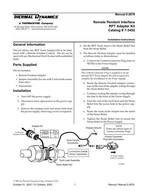
To Remote<br />
Pendant Control<br />
Adapter Kit<br />
Signal<br />
START<br />
Ground<br />
Pins<br />
3 & 4<br />
13<br />
© 2001 by Thermal Dynamics Corp., Printed in USA<br />
Torch Control<br />
Connectors<br />
Torch Lead Assembly<br />
Strain Relief Nut<br />
Connection Details<br />
Shown Separately<br />
<strong>Manual</strong> 0-<strong>2876</strong><br />
Remote Pendant Interface<br />
RPT Adapter Kit<br />
Catalog # 7-3452<br />
Installation Instructions<br />
4. On the RPT Torch remove the Strain Relief Nut<br />
from the Strain Relief.<br />
5. The Remote Pendant Adapter must be installed<br />
as follows (refer to illustrations):<br />
a. Connect the Control Connector Plug (refer to<br />
NOTE) to the Power Supply.<br />
NOTE<br />
The Control Connector Plug is supplied in an additional<br />
RPT Torch Adapter Kit and is required to<br />
complete the installation to the Power Supply.<br />
b. Route the Remote Pendant Adapter connectors<br />
on the end of the adapter wiring through<br />
the Strain Relief Nut.<br />
c. Continue routing the adapter wiring through<br />
the hole in the front of the Power Supply.<br />
d. Feed the end of the torch lead and the Strain<br />
Relief into the access hole in the power supply.<br />
e. Route the wires of the adapter into the notch<br />
of the Strain Relief.<br />
f. Tighten the Strain Relief Nut to secure the<br />
Strain Relief to the Power Supply.<br />
Chassis Ground<br />
NOTE<br />
There are various types of<br />
Control Connector Plugs.<br />
Control Connector<br />
Plug with Connectors<br />
To Power Supply<br />
Control Connector<br />
October 31, 2002 / 31 Octobre, 2002 1 <strong>Manual</strong> / Manuel 0-<strong>2876</strong><br />
A-03226
6. Connect the pilot lead (+) from the replacement<br />
torch to the Power Supply and tighten securely.<br />
7. Connect the Negative / Plasma Lead from the replacement<br />
torch to the Power Supply. Slide the<br />
protective boot over the lead connection.<br />
8. Connect the Control Connector Plug as follows:<br />
a. Connect one connector to the mating Torch<br />
Control Circuit Connector on the torch leads.<br />
b. For four-wire Torch & Lead Assemblies:<br />
Remove the insulating sleeve covering two<br />
joined Torch & Lead wires. Connect the Torch<br />
& Lead wires to the Control Connector and<br />
Remote Pendant Adapter wires as follows:<br />
Leads Assembly or<br />
ATC Adapter Assembly<br />
Small<br />
Socket<br />
Large Pin<br />
Small Pin<br />
Large Socket<br />
Remote Pendant<br />
Adapter<br />
Small Pin<br />
} Not Used<br />
Large<br />
Socket<br />
Large Pin<br />
Large Socket<br />
Pilot Lead<br />
Chassis<br />
Ground<br />
Control<br />
Connector<br />
A-03483<br />
c. The torch or ATC Adapter wires with the large<br />
socket connector and the small pin connector<br />
will not be used in this application. Cut the<br />
insulating sleeve removed previously in half.<br />
Install one half on each unused connector;<br />
secure in place with electrical tape.<br />
c. For two-wire Torch & Lead Assemblies:<br />
Leads<br />
Assembly<br />
Small<br />
Socket<br />
Connect the Torch & Lead wires to the Control<br />
Connector and Remote Pendant Adapter<br />
wires as follows:<br />
Remote Pendant<br />
Adapter<br />
October 31, 2002 / 31 Octobre, 2002 2 <strong>Manual</strong> / Manuel 0-<strong>2876</strong><br />
Small<br />
Pin<br />
Large Pin<br />
Adapter Wire Assembly<br />
Large<br />
Socket<br />
Large<br />
Pin<br />
Small<br />
Socket<br />
Small<br />
Pin<br />
Large Socket<br />
Pilot Lead<br />
A-03484<br />
Chassis<br />
Ground<br />
Control<br />
Connector<br />
9. Tighten the Strain Relief onto the Torch Leads.<br />
10. This kit includes a 14-circuit adapter receptacle.<br />
Use this receptacle if required to connect this<br />
Adapter Kit to the Remote Pendant Control.<br />
11. Reinstall any covers removed.<br />
12. Install the proper torch consumables for the Power<br />
Supply amperage.<br />
13. Reconnect main input power to the Power Supply<br />
and turn the unit ON.<br />
14. Set air pressure and flow according to the Torch<br />
<strong>Manual</strong> or Power Supply <strong>Manual</strong>.<br />
15. Test torch for proper operation.<br />
NOTE<br />
Every effort has been made to provide complete<br />
and accurate information in this manual.<br />
However, the publisher does not assume and<br />
hereby disclaims any liability to any party for<br />
any loss or damage caused by errors or omissions<br />
in this manual, whether such errors result<br />
from negligence, accident or any other<br />
cause.
82 Benning Street, West Lebanon, NH 03784 USA<br />
(603) 298-5711 www.thermal-dynamics.com<br />
Informations Générales<br />
Ce kit permet à n’importe quel kit d’adapteur de torche<br />
de RPT d’être connecté avec un contrôle pendant éloigné.<br />
Le kit peut être employé avec n’importe quel système<br />
mécanisé de torche avec des fils non protégés.<br />
Pièces Fournies<br />
Le kit inclut:<br />
Adapteur Pendant Éloigné<br />
Assemblée de bretelle (pour l’usage avec des fils à<br />
2 fils seulement)<br />
Instructions<br />
Installation<br />
1. Spire OUTRE de l’alimentation d’énergie.<br />
2. Puissance d’entrée principale de débranchement<br />
à l’alimentation d’énergie.<br />
3. Enlevez la torche et le passe-fils existants de<br />
l’alimentation d’énergie, enlevant des couvertures<br />
comme requises.<br />
Au Dispositif<br />
De Télécommande<br />
Adapteur<br />
Signal<br />
DÉBUT<br />
Au Sol<br />
Goupilles<br />
3 & 4<br />
13<br />
Connecteurs De<br />
Contrôle De Torche<br />
Assemblée De Fil De Torche<br />
Écrou de passe-fils<br />
Au sol De Châssis<br />
Détails De Raccordement<br />
Montrés Séparément<br />
Manuel 0-<strong>2876</strong><br />
Interface Pendante Éloignée<br />
Kit D’Adapteur De RPT<br />
Catalogue # 7-3452<br />
Instructions D’Installation<br />
4. Sur la torche de RPT enlevez l’écrou de passe-fils<br />
du passe-fils.<br />
5. L’adapteur pendant éloigné doit être installé<br />
comme suit (référez-vous aux illustrations):<br />
a. connectez la fiche de connecteur de contrôle<br />
(référez-vous à la NOTE) à l’alimentation<br />
d’énergie.<br />
NOTE<br />
La fiche de connecteur de contrôle est fournie dans<br />
un kit supplémentaire d’adapteur de torche de RPT<br />
et est complète exigé l’installation à l’alimentation<br />
d’énergie.<br />
b. itinéraire les connecteurs pendants éloignés<br />
d’adapteur sur l’extrémité du câblage<br />
d’adapteur par l’écrou de passe-fils<br />
c. continuez de conduire le câblage d’adapteur<br />
par le trou dans l’avant de l’alimentation<br />
d’énergie.<br />
d. alimentation la fin du fil de torche et le passefils<br />
dans l’ouverture d’accès dans<br />
l’alimentation d’énergie.<br />
NOTE<br />
Il y a de diverses espèces<br />
des fiches de connecteur<br />
de contrôle.<br />
Fiche De Connecteur De Contrôle<br />
avec Des Connecteurs<br />
Au Connecteur De Contrôle<br />
d'Alimentation D'Énergie<br />
A-03226F<br />
October 31, 2002 / 31 Octobre, 2002 3 <strong>Manual</strong> / Manuel 0-<strong>2876</strong>
e. itinéraire les fils de l’adapteur dans l’entaille<br />
du passe-fils.<br />
f. serrez l’écrou de passe-fils bloqué le passe-fils<br />
à l’alimentation d’énergie.<br />
6. Connectez le fil pilote (+) de la torche de rechange<br />
à l’alimentation d’énergie et serrez solidement.<br />
7. Connectez le fil négatif / plasma de la torche de<br />
rechange à l’alimentation d’énergie. Glissière<br />
l’amorçage protecteur au-dessus du raccordement<br />
de fil.<br />
8. Connectez la fiche de connecteur de contrôle<br />
comme suit:<br />
a. branchez un connecteur au connecteur<br />
joignant de circuit de commande de torche sur<br />
les fils de torche.<br />
b. pour les Assemblées à quatre fils de torche<br />
et de fil:<br />
Petite<br />
Douille<br />
Enlevez la douille isolante couvrant deux fils<br />
jointifs de torche et de fil. Connectez les fils<br />
de torche et de fil au connecteur de contrôle et<br />
les fils pendants éloignés d’adapteur comme<br />
suit:<br />
Assemblée de fils ou<br />
Assemblée d'adapteur d'ATC<br />
Adapteur Pendant<br />
Éloigné<br />
Au sol<br />
De Châssis<br />
Grande Goupille<br />
Petite Goupille<br />
Grande<br />
Douille<br />
Grande Goupille Grande Douille<br />
Fil de Pilote<br />
}<br />
Petite Goupille<br />
Non utilisé<br />
Grande Douille<br />
Connecteur<br />
De Contrôle<br />
A-03483F<br />
c. les fils d’adapteur de torche ou d’ATC avec le<br />
grand connecteur de douille et le petit<br />
connecteur à broches ne seront pas employés<br />
dans cette application. Coupe la douille<br />
isolante enlevée précédemment dans la moitié.<br />
Installez une moitié sur chaque connecteur<br />
inutilisé; bloqué en place avec la bande<br />
électrique.<br />
c. pour les Assemblées à deux fils de torche et<br />
de fil:<br />
Petite<br />
Douille<br />
Connectez les fils de torche et de fil au<br />
connecteur de contrôle et les fils pendants<br />
éloignés d’adapteur comme suit:<br />
Adapteur Pendant<br />
Éloigné<br />
Assemblée<br />
de fils<br />
Petite Grande<br />
Goupille Douille<br />
Grande Goupille<br />
Fil d'adapteur<br />
Grande<br />
Goupille<br />
Petite<br />
Douille<br />
Grande Douille<br />
Fil de Pilote<br />
A-03484F<br />
Au sol<br />
De Châssis<br />
Petite<br />
Goupille<br />
Connecteur<br />
De Contrôle<br />
9. Serrez le passe-fils sur les fils de torche.<br />
10. Ce kit inclut un réceptacle de l’adapteur 14-circuit.<br />
Utilisation ce réceptacle s’il y a lieu de connecter<br />
ce kit d’adapteur au contrôle pendant<br />
éloigné.<br />
11. Réinstallez toutes les couvertures enlevées.<br />
12. Installez les consommables appropriés de torche<br />
pour l’ampérage d’alimentation d’énergie.<br />
13. Raccordez la puissance d’entrée principale à<br />
l’alimentation et à la spire d’énergie l’unité EN<br />
CIRCUIT<br />
14. Placez la pression atmosphérique et le flux selon<br />
le manuel de torche ou le manuel d’alimentation<br />
d’énergie.<br />
15. Torche de test pour le fonctionnement approprié.<br />
NOTE<br />
Tout effort a été fait de fournir des informations<br />
complètes et précises en ce manuel.<br />
Cependant, l’éditeur n’assume pas et ne<br />
dément par ceci aucune responsabilité à aucun<br />
usager pour aucune perte ou à dommages<br />
provoqués par des errors ou omissions en ce<br />
manuel, si un tel résultat d’errors de la<br />
négligence, accident ou tout autre cause.<br />
October 31, 2002 / 31 Octobre, 2002 4 <strong>Manual</strong> / Manuel 0-<strong>2876</strong>


