Manual tehnic automate cafea Necta Koro
Manual tehnic automate cafea Necta Koro
Manual tehnic automate cafea Necta Koro

You also want an ePaper? Increase the reach of your titles
YUMPU automatically turns print PDFs into web optimized ePapers that Google loves.
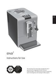
INSTALLATION, USE AND MAINTENANCE MANUAL<br />
<strong>Koro</strong> Espresso UL 120V<br />
USA English<br />
Français<br />
DOC. NO. H 264V 00<br />
EDITION 1 12 - 2005
DICHIARAZIONE DI CONFORMITA’<br />
DECLARATION OF CONFORMITY<br />
DÉCLARATION DE CONFORMITÉ<br />
KONFORMITÄTSERKLÄRUNG<br />
DECLARACIÓN DE CONFORMIDAD<br />
DECLARAÇÃO DE CONFORMIDADE<br />
VERKLARING VAN OVEREENSTEMMING<br />
INTYG OM ÖVERENSSTÄMMELSE<br />
OVERENSSTEMMELSESERKLÆRING<br />
YHDENMUKAISUUSTODISTUS<br />
Valbrembo, 01/04/2005<br />
Dichiara che la macchina descritta nella targhetta di identificazione, è conforme alle disposizioni legislative delle direttive:<br />
98/37/CE, 89/336, 73/23 CEE e successive modifiche ed integrazioni.<br />
Declares that the machine described in the identification plate conforms to the legislative directions of the directives:<br />
98/37/CE, 89/336, 73/23 EEC and further amendments and integrations.<br />
Déclare que l’appareil décrit dans la plaque signalétique satisfait aux prescriptions des directives:<br />
98/37/CE, 89/336, 73/23 CEE et modifications/intégrations suivantes.<br />
Erklärt, daß das im Typenschild beschriebene Gerät den EWG Richtlinien<br />
98/37/CE, 89/336, 73/23 sowie den folgenden Änderungen/Ergänzungen entspricht.<br />
Declara que la máquina descripta en la placa de identificación, resulta conforme a las disposiciones legislativas de las<br />
directivas: 98/37/CE, 89/336, 73/23 CEE y modificaciones y integraciones sucesivas.<br />
Declara que o distribuidor descrita na chapa de identificação é conforme às disposições legislativas das directivas<br />
98/37/CE, 89/336 e 73/23 CEE e sucessivas modificações e integrações.<br />
Verklaart dat de op de identificatieplaat beschreven machine overeenstemt met de bepalingen van de EEG richtlijnen<br />
98/37/CE , 89/336 en 73/23 en de daaropvolgende wijzigingen en aanvullingen.<br />
Intygar att maskinen som beskrivs på identifieringsskylten överensstämmer med lagstiftningsföreskrifterna i direktiven:<br />
98/37/CE, 89/336, 73/23 CEE och påföljande och kompletteringar.<br />
Det erklæres herved, at <strong>automate</strong>n angivet på typeskiltet er i overensstemmelse med direktiverne<br />
98/37/CE, 89/336 og 73/23 EU og de senere ændringer og tillæg.<br />
Forsikrer under eget ansvar at apparatet som beskrives i identifikasjonsplaten, er i overensstemmelse med vilkårene i<br />
EU-direktivene 98/37/CE, 89/336, 73/23 med endringer.<br />
Vahvistaa, että arvokyltissä kuvattu laite vastaa EU-direktiivien 98/37/CE, 89/336, 73/23 sekä niihin myöhemmin tehtyjen<br />
muutosten määräyksiä.<br />
ANTONIO CAVO<br />
C.E.O
TABLE OF CONTENTS<br />
INTRODUCTION PAGE 2<br />
IDENTIFICATION OF THE VENDING MACHINE PAGE 2<br />
IN CASE OF FAILURE PAGE 2<br />
TRANSPORT AND STORAGE PAGE 2<br />
POSITIONING THE VENDING MACHINE PAGE 3<br />
WARNING FOR INSTALLATION PAGE 3<br />
PRECAUTIONS IN USING THE MACHINE PAGE 3<br />
WARNING FOR SCRAPPING PAGE 3<br />
TECHNICAL SPECIFICATIONS PAGE 3<br />
POWER CONSUMPTION PAGE 4<br />
ACCESSORIES PAGE 4<br />
LOADING AND CLEANING PAGE 5<br />
MAINS SWITCHES PAGE 5<br />
HYGIENE AND MAINTENANCE PAGE 5<br />
USING THE VENDING MACHINE PAGE 6<br />
CONTROLS AND INFORMATION PAGE 6<br />
LOADING COFFEE PAGE 6<br />
LOADING INSTANT PRODUCTS PAGE 6<br />
SERVICE FUNCTIONS PAGE 7<br />
FILLING THE WATER SUPPLY TANK PAGE 7<br />
CLEANING THE WASTE TRAYS PAGE 7<br />
DISASSEMBLING AND CLEANING THE MIXERS PAGE 8<br />
CLEANING THE COFFEE UNIT PAGE 8<br />
SUSPENDING FROM USE PAGE 8<br />
INSTALLATION PAGE 9<br />
MAINS SWITCHES PAGE 9<br />
UNPACKING THE VENDING MACHINE PAGE 9<br />
CONNECTION TO THE WATER MAINS PAGE 9<br />
CONNECTING TO THE POWER SUPPLY PAGE 10<br />
INSTALLING THE PAYMENT SYSTEM PAGE 11<br />
WATER SOFTENER UNIT PAGE 11<br />
INSERTING THE LABELS PAGE 11<br />
INITIALISING PAGE 12<br />
FILLING THE WATER SYSTEM PAGE 12<br />
COFFEE UNIT OPERATION PAGE 13<br />
COFFEE DISPENSING CYCLE PAGE 13<br />
DECAFFEINATED DISPENSING CYCLE<br />
CHECKING AND ADJUSTING<br />
PAGE 14<br />
THE MACHINE SETTINGS PAGE 14<br />
STANDARD SETTINGS<br />
ADJUSTING THE BREWING<br />
PAGE 14<br />
CHAMBER VOLUME PAGE 14<br />
WATER TEMPERATURE CONTROL PAGE 15<br />
ADJUSTING THE GRADE OF GRINDING PAGE 15<br />
ADJUSTING THE COFFEE DOSE PAGE 15<br />
English<br />
NOTES ON PROGRAMMING PAGE 16<br />
POWER ON PAGE 16<br />
OPERATING MODES PAGE 16<br />
NORMAL OPERATING MODE PAGE 16<br />
SURFING MODE PAGE 17<br />
FILLER MENU PAGE 17<br />
STATISTICS PAGE 17<br />
SELECTION PRICES PAGE 18<br />
CHANGE TUBES CONTROL PAGE 18<br />
DISPLAYING THE TEMPERATURE PAGE 18<br />
TEST DISPENSING PAGE 18<br />
GSM PRE-ALARMS PAGE 19<br />
EVADTS TRANSFER PAGE 19<br />
FILLER MENU MASKING PAGE 19<br />
TECHNICIAN MENU PAGE 19<br />
FAILURES PAGE 20<br />
PROGRAMMING PARAMETERS PAGE 21<br />
STATISTICS PAGE 25<br />
TEST PAGE 25<br />
MISCELLANEOUS PAGE 26<br />
MAINTENANCE PAGE 27<br />
INTRODUCTION PAGE 27<br />
BREWER UNIT MAINTENANCE PAGE 27<br />
SANITISING THE MIXERS PAGE 28<br />
PERIODICAL CLEANING PAGE 29<br />
PRINTED BOARD FUNCTIONS<br />
AND INDICATOR LAMPS PAGE 30<br />
ACTUATION BOARD PAGE 30<br />
PUSH-BUTTON BOARD PAGE 31<br />
BOILER CONTROL BOARD PAGE 31<br />
PAYMENT SYSTEMS BOARD PAGE 31<br />
HYDRAULIC SYSTEM PAGE 32<br />
PROGRAMMING MENU SUMMARY PAGE 33<br />
WIRING DIAGRAM PAGE 88<br />
© by N&W GLOBAL VENDING SpA 0512 264 - 00<br />
1
INTRODUCTION<br />
This technical documentation is part and parcel of the<br />
vending machine and must always follow the machine<br />
in case it is moved or transfer of ownership, so as to<br />
allow consultation by different operators.<br />
Before starting installation and using the machine, it is first<br />
necessary to carefully read and understand the instructions<br />
contained in this manual, as they offer important information<br />
on installation safety, operating instructions and maintenance.<br />
This manual is divided into three chapters.<br />
The first chapter describes the loading and routine maintenance<br />
operations which are carried out in areas of the<br />
machine accessible with simple use of the door key,<br />
without using any other tools.<br />
The second chapter contains the instructions for correct<br />
installation and all information necessary for optimum use<br />
of the machine.<br />
The third chapter describes maintenance operations which<br />
involve the use of tools to access potentially dangerous<br />
areas.<br />
The operations described in the second and third<br />
chapters must be carried out only by personnel who<br />
have the specific knowledge of the machine functioning<br />
from a point of view of electrical safety and health<br />
regulations.<br />
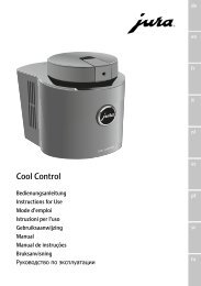
IDENTIFICATION OF THE VENDING<br />
MACHINE AND ITS CHARACTERISTICS<br />
Every machine is identified by its own serial number,<br />
indicated on the rating plate attached inside the cabinet on<br />
the right side.<br />
This plate (see Figure below) is the only one acknowledged<br />
by the manufacturer and indicates all of the data which<br />
readily and safely gives technical information supplied by<br />
the manufacturer. It also assists in spare parts management.<br />
Fig. 1<br />
Product code<br />
Model<br />
Type<br />
Operating voltage<br />
Absorbed power<br />
Water mains<br />
characteristics<br />
IN CASE OF FAILURE<br />
In most cases, any technical problems are corrected by<br />
small repair operations; however, before contacting the<br />
manufacturer we recommend that this manual be read<br />
carefully.<br />
Should there be serious failures or malfunctions, contact<br />
the following:<br />
N&W GLOBAL VENDING SpA<br />
Via Roma 24<br />
24030 Valbrembo<br />
Italy - Tel. +39 - 035606111<br />
TRANSPORT AND STORAGE<br />
To prevent any damage, special care should be taken when<br />
loading or unloading the vending machine.<br />
The machine can be lifted by a motor-driven or manual fork<br />
lift truck, and the blades are to be placed underneath the<br />
machine.<br />
Do not:<br />
- overturn the vending machine;<br />
- drag the vending machine with ropes or similar;<br />
- lift the vending machine by its sides;<br />
- lift the vending machine with slings or ropes;<br />
- shake or jolt the vending machine and its packing.<br />
The machine should be stored in a dry room where the<br />
temperature remains between 0°C and 40°C.<br />
Using the original packing, no more than 2 machines can be<br />
stacked one on top of the other and must always kept<br />
upright as indicated by the arrows on the packing.<br />
Serial<br />
number<br />
Frequency<br />
Current<br />
Boiler data<br />
© by N&W GLOBAL VENDING SpA 0512 264 - 00<br />
2
POSITIONING THE VENDING MACHINE<br />
The vending machine is not suitable for outdoor installation.<br />
It must be positioned in a dry room where the temperature<br />
remains between 2°C and 32°C, and not where water jets<br />
are used for cleaning (e.g. in large kitchens, etc.).<br />
The machine can be placed close to a wall, but with the back<br />
panel at a distance of at least 4 cm from it to ensure correct<br />
ventilation. The machine must never be covered with cloth<br />
or the like.<br />
The machine should be positioned on a level surface.<br />
Important notice!!<br />
Access to the machine interior for maintenance and/or<br />
repairs is via the back panel and from the side panels.<br />
Therefore the machine is designed to be rotated, thus<br />
allowing removal of the back panel and of the side panels.<br />
Installation on a cabinet<br />
The machine can be installed on a table or on any other<br />
suitable stand (recommended height is 830).<br />
If possible, it is advisable to use the special cabinet, which<br />
can house the liquid waste tray, the water supply kit, the<br />
payment system and, in the case of very hard water, the<br />
softener unit.<br />
WARNING FOR INSTALLATION<br />
The machine installation and the following maintenance<br />
operations should be carried out by qualified<br />
personnel only, who are trained in the correct use of the<br />
machine according to the standards in force.<br />
The machine is sold without payment system, therefore the<br />
installer of such system has sole responsibility for any<br />
damage to the machine or to things and persons caused by<br />
faulty installation.<br />
The integrity of the machine and compliance with the<br />
standards of the relevant systems must be checked at<br />
least once a year by qualified personnel.<br />
All packing materials shall be disposed of in a manner which<br />
is safe for the environment.<br />
PRECAUTIONS IN USING THE MACHINE<br />
The following precautions will assist in protecting the<br />
environment:<br />
- use biodegradable products only to clean the machine;<br />
- adequately dispose of all containers of the products<br />
used for loading and cleaning the machine;<br />
- switch the machine off during periods of inactivity, thus<br />
achieving considerable energy savings.<br />
WARNING FOR SCRAPPING<br />
The machine may not be disposed of as ordinary waste; it<br />
must be disposed of in accordance with the provisions of<br />
national laws and regulations, for preventing any possible<br />
negative consequences to the environment and to health.<br />
For correct disposal of the machine, contact the dealer from<br />
whom you have purchased the machine or our after-sales<br />
service.<br />
TECHNICAL SPECIFICATIONS<br />
DIMENSIONS<br />
Height 500 mm<br />
Width 331 mm<br />
Depth 528 mm<br />
Overall depth with door open 724 mm<br />
Weight 27 Kg<br />
Power supply voltage 120 V~<br />
Power supply frequency 60 Hz<br />
Installed power 1400 W<br />
© by N&W GLOBAL VENDING SpA 0512 264 - 00<br />
3<br />
Fig. 2
PAYMENT SYSTEM<br />
Using special kits, the machine can be fitted with payment<br />
systems with MDB protocol.<br />
The payment systems must be housed in the special side<br />
module (optional).<br />
SALE PRICES<br />
A different programmable price can be set for each selection;<br />
the standard setting has the same sales price for all<br />
selections.<br />
WATER SUPPLY<br />
From the mains, with a pressure of 7.3 to 123.3 psig (0.5 to<br />
8.5 bar).<br />
AVAILABLE ADJUSTMENTS<br />
Grade of grinding for espresso coffee.<br />
Espresso coffee dose<br />
Water doses by volume.<br />
Time adjustment for instant product doses.<br />
Water temperature adjusted via software.<br />
CONTROLS<br />
- Presence of water<br />
- Presence of coffee<br />
- Operating temperature reached<br />
SAFETY DEVICES<br />
- Main switch<br />
- Door switch<br />
- top panel switch<br />
- Presence of solid waste tray<br />
- Presence of liquid waste container<br />
- <strong>Manual</strong>-reset boiler safety thermostat<br />
- Air-break float jammed<br />
- Overflow solenoid valve<br />
- Timer protection for:<br />
Pump<br />
Coffee unit ratiomotor<br />
Coffee grinder<br />
- Overheating protection for:<br />
Doser units<br />
Coffee unit ratiomotor<br />
Magnets<br />
Pump<br />
Electric mixers<br />
Coffee grinder motor<br />
- Fuse protection for<br />
Main electrical circuit<br />
Board power supply transformer<br />
CAPACITY OF CONTAINERS<br />
Coffee beans 350 gr<br />
Milk 600 gr<br />
POWER CONSUMPTION<br />
The machine power consumption depends on many factors,<br />
such as the temperature and ventilation of the room<br />
where it is installed, the inlet water and boiler temperature,<br />
etc.<br />
With an ambient temperature of 22° C the following power<br />
consumption levels resulted:<br />
To reach operating temperature 64 W/h<br />
For 24 h in stand-by 1135 W/h<br />
The above power consumption calculated from average<br />
data should only be taken as an indication.<br />
ACCESSORIES<br />
A wide range of accessories can be installed on the<br />
machine to vary its performance:<br />
The installation kits are supplied with their own installation<br />
and test instructions, which must be strictly observed to<br />
ensure the machine safety.<br />
Important notice!!<br />
The use of kits which are not approved by the manufacturer<br />
of the vending machine does not guarantee compliance<br />
with safety standards, especially for energised parts.<br />
The manufacturer declines all responsibility for the use of<br />
non approved components.<br />
Installation and the following testing operations must<br />
be carried out exclusively by personnel who have a<br />
specific knowledge of the machine functions from a<br />
point of view of electrical safety and health regulations.<br />
© by N&W GLOBAL VENDING SpA 0512 264 - 00<br />
4
Chapter 1<br />
LOADING AND CLEANING<br />
MAINS SWITCHES<br />
General<br />
A general switch is fitted outside the machine, disconnecting<br />
the power from the machine without having to open the<br />
door.<br />
The terminal strip supporting the line cable, the fuses<br />
and the noise suppressor stay energised in any case.<br />
Door<br />
When opening the door a special switch disconnects the<br />
power from the machine electrical system to allow the<br />
operations described below, regarding loading and routine<br />
cleaning, in full safety.<br />
Top panel<br />
Also when opening the machine top panel, a switch disconnects<br />
the power, allowing loading operations in a safe<br />
condition.<br />
Fig. 3<br />
1 - Liquid waste tray<br />
2 - Tilting cup support<br />
3 - Brewer unit<br />
4 - Door switch<br />
5 - Coffee funnel<br />
6 - Grinding adjustment knob<br />
7 - Chute for decaffeinated coffee<br />
8 - Top panel switch<br />
9 - Machine top panel<br />
10 - Coffee beans hopper<br />
11 - Coffee container shutter<br />
12 - Instant prod. mixer<br />
13 - Spouts tray release button<br />
14 - Main external switch<br />
All operations requiring the machine to be energized<br />
should be carried out EXCLUSIVELY by qualified personnel,<br />
informed about the specific risks of such<br />
situation.<br />
HYGIENE AND MAINTENANCE<br />
According to current safety and health rules and regulations,<br />
the operator of an automatic vending machine is<br />
responsible for the hygiene of materials that come in<br />
contact with foodstuff; therefore he must carry out maintenance<br />
on the machine to prevent the formation of bacteria.<br />
At installation the hydraulic circuits and the parts in<br />
contact with foodstuff should be fully sanitised to<br />
remove any bacteria which might have formed during<br />
storage.<br />
The machine is not suitable for outdoor installation, it must<br />
be installed in a dry room where the temperature remains<br />
between 2°C and 32°C.<br />
It is advisable that specific sanitising products are used for<br />
cleaning also the surfaces which are not directly in contact<br />
with foodstuff.<br />
Some parts of the machine can be damaged by strong<br />
detergents.<br />
The manufacturer declines all responsibility for damage<br />
caused by non-compliance with the above instructions or<br />
by the use of strong or toxic chemical agents.<br />
Before starting any maintenance operations requiring<br />
parts of the unit to be removed, the machine must<br />
always be switched off.<br />
Do not use sprayed water for cleaning the machine.<br />
© by N&W GLOBAL VENDING SpA 0512 264 - 00<br />
5
USING THE VENDING MACHINES FOR<br />
HOT DRINKS IN OPEN CONTAINERS<br />
(Ex.: plastic cups, ceramic cups, jugs)<br />
Vending machines for drinks in open containers should be<br />
used only to sell and dispense drinks obtained by:<br />
- brewing coffee<br />
- reconstituting instant and lyophilised products.<br />
These products should be declared by the manufacturer as<br />
“suitable for automatic vending” in open containers.<br />
The dispensed products should be consumed immediately.<br />
They should never be preserved and/or packed<br />
for later consumption.<br />
Any other use is unsuitable and thus potentially dangerous.<br />
CONTROLS AND INFORMATION<br />
The machine should operate at an ambient temperature of<br />
2°C to 32°C.<br />
The labels with the selection menu and the operating<br />
instructions supplied with the machine must be inserted at<br />
the time of installation, referring to the selection dose table.<br />
Fig. 4<br />
1 - Red float signal<br />
2 - Lock<br />
3 - Logo label<br />
4 - Alphanumeric display<br />
5 - Selection menu label<br />
6 - Selection buttons<br />
7 - Dispensing spouts<br />
8 - Tilting cup support<br />
9 - Liquid waste tray<br />
The user controls and information are located on the outside<br />
of the door (see Fig. 4).<br />
The Programming button, to access the machine functions,<br />
and mixer cleaning button are located inside the machine on<br />
the right-hand side of the push-button card.<br />
In order to access the programming menus, press the<br />
programming button located on the push-button card.<br />
At this point the machine goes into “Filler menu” mode.<br />
The selection buttons are used for surfing through the<br />
different menus.<br />
NOISE LEVEL<br />
The continuous, weighted equivalent acoustic pressure<br />
level is below 70 dB.<br />
LOADING COFFEE<br />
The cover can be opened only with the door open.<br />
Lift the cover and fill the hopper with coffee, ensuring that<br />
the shutter is fully open (see Fig. 5).<br />
It is advisable to use good quality coffee to avoid<br />
malfunctions to the machine caused by the presence of<br />
impurities.<br />
LOADING INSTANT PRODUCTS<br />
Open the machine top panel and lift the relevant container<br />
lid, fill the single containers with the appropriate products,<br />
taking care not to compress them to prevent packing. Make<br />
sure the products do not contain any clots. Carefully close<br />
the lid, ensuring it is properly secured.<br />
© by N&W GLOBAL VENDING SpA 0512 264 - 00<br />
6<br />
Fig. 5<br />
1 - Coffee funnel<br />
2 - Coffee chute<br />
3 - Decaffeinated chute<br />
4 - Grinding adjustment knob<br />
5 - Coffee container shutter<br />
6 - Decaffeinated loading hatch<br />
7 - Coffee hopper<br />
8 - Machine top panel<br />
Fig. 6
SERVICE FUNCTIONS<br />
Some operations, if enabled from the programming menu,<br />
can be carried out directly with the door closed entering a<br />
password (pressing 5 buttons in a sequence) after pressing<br />
button 7 for more than two seconds.<br />
The possible operations are as follows:<br />
Fig. 7<br />
- consecutive dispensing of several selections in a jug<br />
(jug facilities);<br />
- free dispensing of a selection;<br />
- keypad operation lock/unlock. With the keypad lock on,<br />
the display will indicate “SUSP. SERVICE”<br />
- Mixer wash. The operation must be carried out daily<br />
and every time the machine is refilled to prevent<br />
clogging of the mixer if any product is accidentally<br />
spilled during refilling.<br />
FILLING THE WATER SUPPLY TANK<br />
For the machine using a water tank (optional) located in the<br />
base cabinet or inside or outside the machine, the tank<br />
must be cleaned at least once a week.<br />
CLEANING THE WASTE TRAYS<br />
The waste trays can be easily removed even with the door<br />
closed (see Fig. 8) permitting quick emptying and cleaning.<br />
The coffee container capacity is greater than that of the<br />
waste tray (if the support cabinet is not used).<br />
The machine control software indicates on the display that<br />
the maximum number of selections has been reached with<br />
the message “Waste tray full”.<br />
After a few further selections the machine will lock.<br />
The waste tray must be emptied without switching the<br />
machine off (with the door closed), to allow the software to<br />
detect the operation.<br />
With the solid waste tray removed, the machine is still<br />
available for instant drink selections but indicating the<br />
message “Insert waste tray” on the display and the counters<br />
are reset.<br />
© by N&W GLOBAL VENDING SpA 0512 264 - 00<br />
7<br />
Fig. 8<br />
1 - Solid waste tray<br />
2 - Liquid waste tray detection switch<br />
3 - Solid waste tray detection switch<br />
4 - Liquid waste tray
DISASSEMBLING AND<br />
CLEANING THE MIXERS<br />
When installing the machine, and then at least once a week<br />
or even more frequently according to the use of the machine<br />
and the quality of the inlet water, the mixers and the<br />
dispensing conduits must be thoroughly sanitised (cleaned<br />
and disinfected), to guarantee proper hygiene of the dispensed<br />
products.<br />
The parts to be cleaned are as follows:<br />
- powder deposit drawers, mixer and instant drink dispensing<br />
conduit;<br />
- dispensing spouts;<br />
- spout support tray;<br />
- remove the powder and the water funnels, the feeders,<br />
the powder deposit drawers and the mixer wheels from<br />
the mixers (see Fig. 9);<br />
Fig. 9<br />
1 - Dispensing spouts<br />
2 - Spouts support release button<br />
3 - Funnel securing ring nut<br />
4 - Mixer wheel<br />
5 - Water funnel<br />
6 - Powder deposit drawer<br />
7 - Product funnel<br />
8 - Product conveying dispensing pipette<br />
- in order to remove the water funnel, rotate the green<br />
ring nut clockwise;<br />
pay special attention to closing it fully during<br />
reassembly;<br />
- in order to remove the impellers, block the disk fitted<br />
on the mixer shaft with a finger (see Fig. 10 and 11).<br />
CLEANING THE COFFEE UNIT<br />
Every time coffee is refilled, or at least once a week, any<br />
powder residue should be removed from the external parts<br />
of the coffee unit, particularly from the coffee funnel area<br />
(see Fig. 24), using a brush or a small vacuum cleaner.<br />
SUSPENDING FROM USE<br />
If for any reason the machine is switched off for a period<br />
exceeding the use-by date of the products, the following will<br />
be necessary:<br />
- completely empty the containers and thoroughly wash<br />
them with the sanitising products used to clean the<br />
mixers;<br />
- completely empty the grinder by dispensing coffee until<br />
the empty condition is indicated.<br />
- completely empty the hydraulic system.<br />
© by N&W GLOBAL VENDING SpA 0512 264 - 00<br />
8<br />
Fig. 10<br />
Fig. 11
Chapter 2<br />
INSTALLATION<br />
Installation and the following maintenance operations should<br />
be carried out with the machine switched on and therefore<br />
by qualified personnel only, who are trained in the correct<br />
use of the machine and informed about the specific risks of<br />
such situation.<br />
The machine is not suitable for outdoor installation, it must<br />
be installed in a dry room where the temperature remains<br />
between 2°C and 32°C.<br />
The machine cannot be installed where water jets are used<br />
for cleaning.<br />
At installation the hydraulic circuits and the parts in<br />
contact with foodstuff should be fully sanitised to<br />
remove any bacteria which might have formed during<br />
storage.<br />
MAINS SWITCHES<br />
General<br />
A general switch is fitted outside the machine, disconnecting<br />
the power from the machine without having to open the<br />
door.<br />
The terminal strip supporting the line cable, the fuses<br />
and the noise suppressor stay energised in any case.<br />
Door<br />
When opening the door a special micro-switch disconnects<br />
the power from the machine electrical system.<br />
To energize the system with the open door, simply insert<br />
the special key into the slot (see Fig. 12).<br />
Top panel<br />
Also when opening the machine top panel, a switch disconnects<br />
the power, allowing loading operations in a safe<br />
condition.<br />
Fig. 12<br />
1 - Door switch<br />
2 - Top panel switch<br />
3 - Network fuses<br />
4 - Main external switch<br />
The switch on key MUST NOT be left inside the machine,<br />
it must be kept by the qualified personnel trained<br />
in the use of the machine.<br />
With the door open, there is no access to energised<br />
parts. Inside the machine, the only parts that stay<br />
energised are those protected by covers and carrying a<br />
plate with the warning “Disconnect the power before<br />
removing the protective cover”.<br />
Before removing such covers disconnect the power<br />
supply cable from the grid.<br />
The door can be closed only after removing the yellow key<br />
from door switch and closing the machine top panel.<br />
UNPACKING THE VENDING MACHINE<br />
After removing the packing, ensure that the machine is<br />
intact.<br />
If in doubt do not use the machine.<br />
No packing elements (i.e. plastic bags, polystyrene<br />
foam, nails, etc.) should be left within the reach of<br />
children, as they are potentially dangerous.<br />
Packing materials must be disposed of in authorised<br />
containers and the recyclable ones must be recovered by<br />
qualified companies.<br />
Important notice!!<br />
The machine should be positioned on a level surface.<br />
CONNECTING THE MACHINE TO THE<br />
WATER MAINS<br />
Some models can be connected to the drinking water<br />
mains, taking into account law provisions in force in the<br />
country where the machine is installed.<br />
The water pressure must be 7.3 to 123.3 psig (0.5-8.5 bar).<br />
Run some water from the mains until it is clear and without<br />
impurities.<br />
Use a hose (also available as a kit) capable of withstanding<br />
the water mains pressure and suitable for use with foodstuff<br />
(min. inside diameter of 6 mm) to connect the water supply<br />
to the union (3/4" gas) of the water inlet solenoid valve (see<br />
Fig. 13).<br />
It is good practice to install the water supply tap outside<br />
the machine in an easily accessible position.<br />
© by N&W GLOBAL VENDING SpA 0512 264 - 00<br />
9<br />
Fig. 13<br />
1 - Water inlet union (3/4" gas)<br />
2 - Water supply hose<br />
3 - Overflow hose
OVERFLOW DEVICE<br />
The water inlet solenoid valve (see Fig. 13) is equipped with<br />
an overflow device which mechanically stops the water inlet<br />
if there is a malfunction in the solenoid valve or in the boiler<br />
water level control device.<br />
To restore normal operation, proceed as follows:<br />
- drain the water contained in the overflow hose;<br />
- shut off the water supply using the tap outside the<br />
machine;<br />
- loosen the nut which secures the solenoid valve supply<br />
hose to relieve the water mains residual pressure and<br />
then tighten again (see Fig. 13);<br />
- open the tap and switch the machine on.<br />
CONNECTING THE MACHINE TO THE<br />
POWER SUPPLY<br />
The machine is designed to operate under a single-phase<br />
120 V~ voltage and is protected by 15 A fuses.<br />
Do not connect the machine to a circuit operating at<br />
more than 150 V to ground.<br />
Before making the connection, ensure that the rating<br />
corresponds to that of the power grid, and more specifically:<br />
- the supply voltage rating must be within the range<br />
recommended for the connection points;<br />
- the main switch should be capable of withstanding the<br />
peak load required, and at the same time ensure proper<br />
omnipolar disconnection from the power grid with an<br />
opening gap of the contacts of at least 3 mm.<br />
The switch, the power outlet and the plug must be<br />
located in an easily accessible position, so that the<br />
cable can be disconnected in the event of intervention..<br />
The power supply cable is of the type with a fixed plug. Any<br />
replacement of the power supply cable (see Fig. 14) should<br />
be made by qualified personnel only, using cables of the<br />
type UL SJTO 3x16 AWG.<br />
The electrical safety of the machine is ensured only when<br />
it is correctly earthed according to the safety standards in<br />
force.<br />
This fundamental safety requirement must be duly<br />
verified, and if in doubt the system must be carefully<br />
tested by qualified technicians.<br />
Do not use adapters, multiple sockets and/or extensions.<br />
Before switching the machine on, be sure it is correctly<br />
connected to the water mains and the cut-off valve is open.<br />
THE MANUFACTURER DECLINES ALL RESPONSIBIL-<br />
ITY FOR ANY DAMAGE CAUSED BY NON-COMPLI-<br />
ANCE WITH THE ABOVE MENTIONED SAFETY RULES.<br />
© by N&W GLOBAL VENDING SpA 0512 264 - 00<br />
10<br />
Fig. 14<br />
1 - Connection terminal strip<br />
2 - Cable clamp<br />
3 - Cable from the mains
INSTALLING THE PAYMENT SYSTEM<br />
The machine is sold without payment system, therefore<br />
the installer of such a system is responsible for any<br />
damage to the machine or to things and persons<br />
caused by faulty installation.<br />
Payments systems such as validators, “change-giver” and<br />
“cashless” can be installed by using the specific kits.<br />
Payment systems such as “change giver” must be physically<br />
housed in the special side module (optional).<br />
WATER SOFTENER UNIT<br />
The machine is sold without water softener.<br />
In the event of connection to very hard water, a water<br />
softener unit should be installed.<br />
The water softener, available as accessory, must be<br />
replaced or regenerated regularly following the directions<br />
from the manufacturer.<br />
Use water softeners with capacity that is adequate to the<br />
effective needs of the machine.<br />
In the event of water supply from the tank, the special<br />
filtering cartridges can be used.<br />
The cartridges must be replaced periodically according to<br />
the water quality and to the instructions from the manufacturer.<br />
INSERTING THE PRODUCT LABELS<br />
The menu and instruction labels are supplied with the<br />
machine and must be inserted at the time of installation<br />
according to the layout and to the language (see “selection<br />
dose” table).<br />
To access the label insertion slots, remove the side cover<br />
of the door, secured with two screws (see Fig. 15).<br />
Fig. 15<br />
1 - Side cover<br />
2 - Fastening screws<br />
3 - Selection menu label<br />
4 - Slots for inserting the labels<br />
5 - User instruction label<br />
POWER ON<br />
Before switching the machine on, ensure that the grounds<br />
trays and the container lids are into place.<br />
Each time the machine is switched on, the display shows<br />
the following message:<br />
POWER ON<br />
Confirm?<br />
Press any selection button to continue.<br />
It is possible to program the machine to enable the function<br />
that displays the controls to be performed before starting<br />
the machine, and namely:<br />
Tubing (nozzles etc.)<br />
Mixers<br />
Powder feeder<br />
Coffee shutter<br />
Power on<br />
For all controls the request “Confirm?” is indicated on the<br />
display.<br />
Press any selection button to continue.<br />
The function of presenting the list of preliminary controls<br />
can be enabled (disabled by default) from the programming<br />
menu.<br />
At the end of the power on cycle, the display indicates the<br />
software version number to which referring for consulting<br />
the programming manual.<br />
<strong>Koro</strong> ES<br />
REV 1.0<br />
The machine can be programmed for displaying, for a few<br />
second, the number of selections made.<br />
After a few seconds the display shows the message:<br />
Ready for use<br />
SELECT THE DRINK<br />
© by N&W GLOBAL VENDING SpA 0512 264 - 00<br />
11
INITIALISING<br />
When the “Initialise” function is displayed the vending<br />
machine can be initialised restoring all default data.<br />
This function should be used the first time the machine is<br />
switched on and in the event of a memory data error or<br />
reprogramming of the board.<br />
All statistic information will be reset.<br />
Press confirm button “ ” and the display will indicate the<br />
message “Confirm?”. Press button “ ” again to display the<br />
first variable parameter to define the machine configuration.<br />
The available options (blinking) can be scrolled with the “ ”<br />
and “ ” buttons, the selection is confirmed with button “ ”<br />
and the next parameter is presented. When pressing button<br />
“ ” after the last parameter the display will show the<br />
message “Working” for a few seconds and the machine is<br />
initialised.<br />
The parameters are as follows:<br />
“Country” Type of doses to be<br />
used for the selections<br />
“Layout” Layout of containers and<br />
selection menu from the<br />
available ones<br />
“Tank” Water supply from the mains<br />
or from a tank<br />
N.B.: When the machine is switched on for the first time or<br />
in any case after initialising, as well as the list of controls<br />
to be performed, also the language used for the messages<br />
on the display is proposed.<br />
The available languages can be scrolled with the “ ” and “ ”<br />
buttons, and the selection is confirmed with button “ ”.<br />
Unless the machine is initialised, the language request is<br />
not made again.<br />
In any case it will be possible to change it through the<br />
specific function in the “Technician” menu.<br />
FILLING THE WATER SYSTEM<br />
If the machine is connected to the water mains, when it is<br />
switched on the conditions of air-break (full or empty), pump<br />
and boiler priming (pressure) are checked.<br />
If required by the conditions, the machine will automatically<br />
start an installation cycle, and namely:<br />
- the message “Installation” will be shown on the display<br />
for the entire duration of the cycle;<br />
- the water mains solenoid valve is opened or the pump<br />
is started to fill the air-break;<br />
- the milk solenoid valve is opened so that the air may<br />
be bled from the boiler and from the hydraulic system,<br />
and 400 cc. of water filled.<br />
N.B.: If there is no water flow from the mains during the installation<br />
cycle, the machine will stop until water is resumed or the machine<br />
is switched off.<br />
IMPORTANT NOTICE!!!<br />
If a considerable amount of air bubbles is formed in the<br />
water system, for example during maintenance, it is possible<br />
that an installation cycle is automatically started when<br />
the machine is switched on.<br />
Versions with internal tank<br />
For models with an internal tank, when the machine is<br />
first switched on, the installation procedure MUST BE<br />
carried out manually (see relevant chapter).<br />
© by N&W GLOBAL VENDING SpA 0512 264 - 00<br />
12
COFFEE UNIT OPERATION<br />
COFFEE DISPENSING CYCLE<br />
When confirming the switch on cycle of the machine, by<br />
pressing a selection button, the coffee unit is rotated<br />
completely before the normal cycle, to ensure that the<br />
device is in the correct start position.<br />
When making a coffee selection, the grinder will run for the<br />
time necessary to fill the brewing chamber with the coffee<br />
dose set via software.<br />
Fig. 16<br />
1 - Brewing chamber<br />
2 - Handle<br />
3 - Upper piston<br />
4 - Lower piston<br />
5 - Piston return spring<br />
6 - Swinging lever<br />
7 - Pre-brewing spring<br />
When the ground coffee dose is reached, the ratiomotor<br />
engaged with the handle (2) located outside the assembly<br />
rotates by 180°, making the brew chamber swing and<br />
lowering the upper piston (3) (see Fig. 16).<br />
Due to the water pressure, the pre-brewing spring (7) sinks<br />
and the lower piston (4) goes down 3 mm, thus forming a<br />
water cushion which allows an even use of the coffee dose.<br />
At the end of the dispensing cycle and during a pause of 3<br />
seconds, the pre-brewing spring (7) will discharge the water<br />
through the third way of the dispensing solenoid valve,<br />
lightly pressing the used coffee dose.<br />
By completing its rotation, the ratiomotor makes the swinging<br />
lever (6) lift the pistons and the coffee dose.<br />
At the same time, when the brewing chamber returns to its<br />
vertical position, the scraper on the coffee hopper stops the<br />
used coffee dose and drops it.<br />
Pulled by the spring (5), the lower piston now returns to the<br />
bottom dead centre.<br />
© by N&W GLOBAL VENDING SpA 0512 264 - 00<br />
13<br />
Fig. 17<br />
1 - Brewing chamber<br />
2 - Handle<br />
3 - Upper piston<br />
4 - Lower piston<br />
5 - Piston return spring<br />
6 - Swinging lever<br />
7 - Pre-brewing spring
DECAFFEINATED DISPENSING CYCLE<br />
The machine is supplied with a door, for manually inserting<br />
ground coffee, locked by default.<br />
According to the location needs, it is possible to<br />
unlock the door to be able to manually insert decaffeinated<br />
coffee or similar.<br />
It is necessary to ensure that other product types are not<br />
inserted.<br />
The door for introducing the decaffeinated coffee is fitted<br />
with a magnet that, through a sensor located on the door,<br />
signals to the machine that the door was opened.<br />
Fig. 18<br />
1 - Door opening signalling magnet<br />
2 - Decaffeinated door<br />
3 - Decaffeinated funnel<br />
4 - Coffee funnel<br />
The display indicates the blinking message:<br />
Decaffeinated<br />
Decaffeinated coffee based selections are dispensed without<br />
running the coffee grinder.<br />
The brewing cycle is the same as in the espresso coffee.<br />
By pressing the special “reset decaffeinated” button before<br />
dispensing the drink, the “decaffeinated” pre-selection is<br />
cancelled, the machine rotates the brewer unit and returns<br />
to normal operating mode.<br />
CHECKING AND ADJUSTING<br />
THE MACHINE SETTINGS<br />
To get the best results from the product used, the following<br />
should be checked:<br />
That the used coffee dose is lightly compressed and<br />
damp.<br />
The grade of grinding of ground coffee.<br />
The dose weight of the instant products.<br />
The drink temperature.<br />
The water dose.<br />
Should the standard settings need to be changed, proceed<br />
as indicated in the next sections of this manual.<br />
The weight of products, the water dose and temperature are<br />
directly controlled by the microprocessor.<br />
To adjust them it is therefore necessary to follow the<br />
programming procedures.<br />
STANDARD SETTINGS<br />
The vending machine is supplied with the following settings:<br />
- coffee temperature (at the spout) approx. 70÷80° C;<br />
- instant product temperature (at the spout) 70÷80°C<br />
approx.;<br />
The machine standard settings assign the same price to all<br />
selections, as indicated in the selection dose table.<br />
ADJUSTING THE BREWING<br />
CHAMBER VOLUME<br />
When the upper piston is correctly positioned, the coffee<br />
unit can operate with coffee doses of 7.5 to 10.5 gr.<br />
To change the piston position (see Fig. 19) do as follows:<br />
- remove the snap ring from its seat;<br />
- place the piston in the proper adjusting notches:<br />
.less deep notches for 9.5 to 9.5 gr doses (8 oz);<br />
.deeper notches for 8.5 to 10.5 gr doses (12 oz).<br />
© by N&W GLOBAL VENDING SpA 0512 264 - 00<br />
14<br />
Fig. 19<br />
1 - Snap ring<br />
2 - Upper piston<br />
3 - Reference fins
WATER TEMPERATURE CONTROL<br />
The boiler temperature is controlled by the software and can<br />
be adjusted directly from the menu.<br />
ADJUSTING THE GRADE OF GRINDING<br />
When a variation in the grade of grinding is desired, turn the<br />
relevant adjusting knob on the grinder (see Fig. 20) and<br />
more specifically:<br />
Fig. 20<br />
1 - Coffee grinder<br />
2 - Grinding adjusting knob<br />
3 - Coffee conduit<br />
4 - Coffee funnel<br />
- turn the knob anticlockwise for coarser grinding;<br />
- turn the knob clockwise for finer grinding.<br />
For optimum results, it is advisable to vary the grade of<br />
grinding with the coffee grinder motor running.<br />
N.B.: After adjustment of the grade of grinding, at least<br />
3 test selections must be performed in order to check<br />
the new grade of grinding for ground coffee:<br />
The finer the grade of grinding the longer the time necessary<br />
for dispensing the coffee and vice versa.<br />
After the adjustment it will be necessary to check also the<br />
amount of ground coffee, which can have small variations.<br />
ADJUSTING THE COFFEE DOSE<br />
The grinder is fitted with a sensor that can count the number<br />
of rotations of the grinding wheels.<br />
This allows the control software of the machine to determine<br />
the number of rotations, and therefore grams of<br />
coffee, for each single selection.<br />
With the dose programming procedures (after setting the<br />
output of the grinder in gr/s) it will be possible to set the<br />
grams (7.5 to 10.5 gr) of ground coffee for each selection.<br />
To take the dose just remove the coffee unit and select the<br />
special item from “Special functions” of the “Technician”<br />
menu (see relevant section).<br />
Important notice!!!<br />
To refit the coffee unit, pay special attention to the<br />
piston position. Reference notches on the handle and<br />
on the unit case should match (see Fig. 24).<br />
© by N&W GLOBAL VENDING SpA 0512 264 - 00<br />
15
Notes on programming<br />
The machine electronic control allows or not the use of<br />
many functions:<br />
All of the available functions are described in the machine<br />
program, including the ones that are not used for the<br />
specific configuration of the model (layout).<br />
The machine is supplied with a dose table, describing the<br />
different functions and layouts available for the specific<br />
model and the flowchart of the programming menu.<br />
Below is listed a summary explanation of the main functions<br />
useful for managing the operation of the machine, not<br />
necessarily in the order in which they are displayed in the<br />
menu.<br />
For further information and detailed explanations refer to the<br />
programming manual available through our sales organisation<br />
or at our after-sales service.<br />
The software version can be updated using the specific<br />
systems (PC, Flash, Upkey etc.).<br />
The messages on the display that indicate the current<br />
operation are fixed, while any action required by the user is<br />
blinking.<br />
POWER ON<br />
Each time the machine is energised, (if the function is<br />
enabled) the display presents the list of controls to be<br />
performed before starting the machine, and namely:<br />
Tubing (nozzles etc.)<br />
Mixers<br />
Powder feeder<br />
Coffee shutter<br />
Power on<br />
POWER ON<br />
Confirm?<br />
For all controls the request “Confirm?” is indicated on the<br />
display.<br />
Press any selection button to continue.<br />
The function of presenting the list of preliminary controls<br />
can be enabled from the programming menu.<br />
At the end of the power on cycle, the display indicates the<br />
software version number to which referring for consulting<br />
the programming manual.<br />
<strong>Koro</strong> ES<br />
REV 1.0<br />
The machine can be programmed for displaying, for a few<br />
second, the number of selections made.<br />
After a few seconds the display shows the message:<br />
Ready for use<br />
SELECT THE DRINK<br />
© by N&W GLOBAL VENDING SpA 16<br />
OPERATING MODES<br />
The machine can be in three different operating modes.<br />
According to the operating mode, the buttons take on<br />
different functions.<br />
The available operating modes are as follows:<br />
FUNCTIONS<br />
Normal operating mode Coins accepted<br />
products dispensed<br />
Filler menu Test dispensing<br />
machine maintenance<br />
Technician menu Programming<br />
different parameters<br />
NORMAL OPERATING MODE<br />
During the normal operating mode the display shows the<br />
message for the user with the prompt to select the drink.<br />
The function of the buttons can be different according to<br />
the layout and to the choices made during programming.<br />
SELECT THE DRINK<br />
When inserting coins or a payment system, the available<br />
credit is displayed.<br />
SELECT THE DRINK<br />
Credit= 0.50<br />
During the drink dispensing, also a status bar is shown,<br />
indicating the drink preparation status.<br />
DRINK SELECTED<br />
In the event of a malfunction detected by the control<br />
system, an error message will be displayed indicating the<br />
type of problem.<br />
SELECTION NOT AVAILABLE<br />
"Failure name"<br />
At the end of dispensing, the display indicates for a few<br />
seconds the request to pick up the drink and the machine<br />
is preset for the next selection.<br />
DRINK READY<br />
TAKE<br />
0512 264 - 00
SURFING MODE<br />
The interaction between system and user occurs through<br />
the following components:<br />
- Liquid crystal display (LCD) 2 lines of 16 characters.<br />
- External direct selection push-button panel which takes on<br />
the following functions when in “Filler” and “Technician”<br />
mode (see Fig. 21):<br />
Fig. 21<br />
Scrolling buttons “ ” and “ ”:<br />
To move to the next or previous menu option and change<br />
the values (up or down).<br />
Confirm button “ ”:<br />
To move from a menu to a sub-menu or it is used to confirm<br />
the current information on the display.<br />
Exit key “ ”:<br />
to return from a sub-menu to the higher level menu, or to<br />
clear the data on the display.<br />
It is also used for going from “Technician” mode to “Filler”<br />
mode and vice versa.<br />
With the door open, the presence of the magnet on the<br />
decaffeinated coffee door cannot be detected correctly.<br />
The first line on the display indicates, after the number and<br />
the active function of the menu, a symbol that simulates the<br />
status of the door:<br />
= Door closed (grinding is carried out during the test<br />
selections);<br />
= Door open (grinding is not carried out during the test<br />
selections);<br />
to change the status of the decaffeinated door’s simulator,<br />
press the last button to the right.<br />
Fig. 22<br />
FILL> n.n.n<br />
COMPLETE DISP.<br />
FILLER MENU<br />
When pressing once the programming button, the machine<br />
goes into “Filler menu” mode.<br />
The display presents the first item of the “filler” menu with<br />
a series of numbers next to it, identifying the level of the<br />
current menu.<br />
Press the confirm button “ ” to access the menu.<br />
Press the exit button “ ” to return to the previous menu.<br />
FILL><br />
STATISTICS<br />
FILL><br />
Print statistics<br />
FILL><br />
Display statistics<br />
FILL><br />
Reset statistics<br />
© by N&W GLOBAL VENDING SpA 0512 264 - 00<br />
17<br />
Fig. 23<br />
1 - Mechanical counter<br />
2 - Wash button<br />
3 - Programming access button<br />
4 - Push-button card cover
STATISTICS<br />
All data concerning sales and the machine operations is<br />
stored in both total counters and relative counters, which<br />
can be reset without losing total data.<br />
Printing<br />
Connect an RS232 serial printer having a Baud rate of 9600,<br />
8 data bit, no parity, 1 stop bit to the serial port located on<br />
the push button board to print all of the statistics.<br />
The printout will also contain the machine information, the<br />
date and the software version.<br />
To connect the printer, do as follows:<br />
- press the confirm print button “ ”, displaying the message<br />
“Confirm?”;<br />
- connect the printer before confirming;<br />
- press the confirm button “ ” to start printing.<br />
Displaying<br />
Press the confirm button “ ” to display in a sequence the<br />
same data obtained with the statistic printing, for both total<br />
and relative counters.<br />
Deleting<br />
Statistics can be reset for relative counters globally (all<br />
types of data) or selectively for:<br />
- selections<br />
- failures<br />
- coin mechanism data<br />
Press the confirm button “ ”, and the message “Confirm?”<br />
starts blinking.<br />
Press the confirm button “ ”, the message “Working” is<br />
displayed for a few seconds and all statistics are reset.<br />
SELECTION PRICES<br />
This function is used for changing the sales price for each<br />
single selection and for each time band that may be set.<br />
FILL><br />
PRICES<br />
PRICES<br />
Selection #<br />
Selection #<br />
Time band #<br />
Time band #<br />
Price # #. # #<br />
© by N&W GLOBAL VENDING SpA 18<br />
CHANGE TUBES CONTROL<br />
By accessing the “Tube control” function the change tubes<br />
can be filled or released manually.<br />
Confirm refilling, and the display will indicate<br />
“Credit: ——” which is the value of money available in<br />
change the tubes; insert the desired coin into the validator<br />
and the display will indicate the value of money available in<br />
the change tubes.<br />
When confirming releasing, it will be possible to decide<br />
which tube to release. Each time the confirm button “ ” is<br />
pressed, a coin is ejected from the active tube.<br />
FILL><br />
Tubes control<br />
FILL><br />
Fill tubes<br />
Credit:#####<br />
FILL><br />
Release tubes<br />
Credit:#####<br />
Release tubes<br />
Tube A ÷ X<br />
DISPLAYING THE TEMPERATURE<br />
With this function it is possible to read the boiler temperature<br />
directly in °C.<br />
The symbol “ ” indicates that the boiler heating element is<br />
not heating.<br />
The symbol “ ” indicates that the boiler heating element is<br />
heating.<br />
FILL><br />
Boiler temperature<br />
Boiler temperature<br />
T. = ##,# °C<br />
0512 264 - 00
TEST DISPENSING<br />
For complete or partial dispensing tests (water, powder,<br />
only and without accessories) each button (or combination<br />
of buttons according to the model) is assigned a selection<br />
(see the dose selection table).<br />
FILL><br />
TEST<br />
FILL><br />
Complete selection<br />
FILL><br />
Water only<br />
FILL><br />
Powder only<br />
N.B. For espresso coffee based selections, only the<br />
additions are dispensed with the partial dispensing of<br />
powder and water; if a selection requires no addition<br />
the message “Sel. disabled”, indicating a disabled<br />
selection, will be displayed.<br />
GSM PRE-ALARMS<br />
The control software can send, via GSM modem, a signal<br />
indicating an “ending product” signal, when there is only a<br />
certain (programmable) number of pieces or grams of<br />
powder of a given product left. With this function the<br />
counters that control the pre-alarms are reset.<br />
EVADTS TRANSFER<br />
When activating this function, the machine awaits the<br />
connection with a device to acquire the EVADTS statistics.<br />
FILLER MENU MASKING<br />
The functions described in this chapter can be inhibited<br />
selectively from the “technician menu”.<br />
© by N&W GLOBAL VENDING SpA 0512 264 - 00<br />
19<br />
FILL><br />
FILL><br />
GSM<br />
EVADTS<br />
FILL><br />
Reset pre-alarm counters<br />
FILL><br />
Connection
TECHNICIAN MENU<br />
Below is listed a summary explanation of the main functions<br />
useful for managing the operation of the machine,<br />
grouped by use logic and not necessarily in the order in<br />
which they are displayed in the menu.<br />
The software version can be updated using the specific<br />
systems (PC, Flash, Upkey etc.), therefore all is described<br />
in this chapter is only to be taken as an example.<br />
For further information and detailed explanations refer to the<br />
dose selection table supplied with the machine and to the<br />
programming manual available through our sales organisation,<br />
at our after-sales service, referring to the version<br />
number that is displayed when switching on the machine.<br />
When pressing once the programming button located on the<br />
coin mechanism compartment, the machine goes into<br />
“Filler menu” mode.<br />
When pressing button “ ” from “Filler” mode, the machine<br />
is preset to “Technician menu”.<br />
Note:<br />
When pressing button “ ” from “Technician” mode, the<br />
machine returns to “Filler menu” mode.<br />
The first option of the programming menu is displayed,<br />
enabling the following functions:<br />
FAILURES<br />
The machine id equipped with various sensors for monitoring<br />
the different functional units.<br />
When a malfunction is detected, a failure is “indicated” and<br />
the machine (or part of it) is placed out of service. The failure<br />
is stored in the appropriate counters.<br />
The failure monitored by the software may regard functional<br />
units not present in the specific model; they are in any case<br />
listed when scrolling the menu.<br />
The possible failures are indicated in the following cases:<br />
Water failure<br />
If the float is closed for more than one minute, the water inlet<br />
solenoid valve will remain energized until the water flow is<br />
restored.<br />
If the machine is equipped with an internal water supply tank<br />
the pump will be switched off.<br />
Waste container full<br />
The machine locks if the liquid waste container float is<br />
triggered.<br />
Air-break<br />
The machine is locked if after 10 selections the float has<br />
never signalled the lack of water.<br />
Volumetric counter<br />
Failed computation of the volumetric counter (flow-meter)<br />
within a max. given time.<br />
Boiler<br />
The machine will lock if after the maximum time of heating<br />
from the machine start, or from the last selection, the boiler<br />
fails to reach the operating temperature.<br />
© by N&W GLOBAL VENDING SpA 20<br />
CAN-BUS board<br />
Failed dialogue between C.P.U. board and can-bus board<br />
(FB unit control).<br />
Coin mechanism<br />
The machine is locked if it receives a pulse longer than 2<br />
seconds on a validator line or the communication with the<br />
serial coin mechanism does not take place for more than 30<br />
seconds (Executive protocol) or 75 seconds (BDV protocol).<br />
Machine lock<br />
The machine is locked upon reaching the number of<br />
selections set with the “selection counter” function.<br />
Grinder blockage<br />
If the coffee grinder does not rotate or rotates too slowly, the<br />
espresso coffee selections are disabled. Decaffeinated<br />
based selections remain available.<br />
Espresso unit<br />
Due to mechanical blocking of the unit.<br />
The machine is not locked, but all coffee-based selections<br />
are disabled.<br />
No coffee<br />
If the function is enabled from the programming menu, the<br />
display indicates the message “Insert coffee” if the grinder<br />
exceeds the grinding velocity for longer than 5 seconds.<br />
RAM Data<br />
One or more areas of the RAM contain wrong data which<br />
was corrected with the default values.<br />
The machine will continue to function, but it would be<br />
advisable to initialise as soon as possible.<br />
Fresh-brew piston<br />
Due to wrong positioning of the unit.<br />
The machine is not locked, but all fresh product based<br />
selections are disabled.<br />
Fresh-brew scraper<br />
Wrong positioning of the grounds ejection scraper.<br />
The machine is not locked, but all fresh product based<br />
selections are disabled.<br />
Espresso lock<br />
The machine is locked upon reaching the number of coffee<br />
selections set separately with the “selection counter” function.<br />
Instant prod. lock<br />
The machine is locked upon reaching the number of instant<br />
product selections set separately with the “selection counter”<br />
function.<br />
0512 264 - 00
READING PRESENT FAILURES<br />
When the “Failure” function is displayed, press the confirm<br />
button “ ” to display the present failures.<br />
If no failures are currently present, after pressing the<br />
confirm button “ ” the message “End failures” will be<br />
displayed.<br />
TECH><br />
FAILURES<br />
TECH><br />
FAILURES<br />
TECH><br />
SET PARAMETERS<br />
TECH><br />
FAILURE LIST<br />
End of failures<br />
RESETTING<br />
By confirming this function all current failures will be reset.<br />
TECH><br />
RESET FAILURES<br />
PROGRAMMING PARAMETERS<br />
CASH<br />
This set of functions controls all parameters regarding the<br />
payment systems and the sales prices.<br />
CASH<br />
Selection prices<br />
Four different prices can be set for each selection according<br />
to the programmed time bands for when the time table<br />
option is enabled.<br />
For each of the 4 time bands prices (0 to 65,535) can be<br />
programmed globally (same price for all selections) or for<br />
the single selections.<br />
Should the majority of products be sold at the same price,<br />
it will be convenient to set the price globally and then<br />
change the figure of the selections with different prices.<br />
Time bands<br />
Four programmable time bands are provided for selling<br />
products at different prices.<br />
The time periods are programmable for beginning and end<br />
time by hours (00 to 23) and minutes (00 to 59).<br />
If the values for start and end of the time band are set to<br />
00.00 the time period is disabled.<br />
The reference time is kept by an internal clock, programmable<br />
as:<br />
day/month/year week-day 1-7<br />
and then<br />
hour/minutes/seconds.<br />
If the values for start and end of the time band are set to<br />
00.00 the time period is disabled.<br />
Coin mechanisms<br />
It is possible to decide which of the payment system<br />
protocols available are to be enabled for the functions.<br />
The available payment systems are:<br />
- Validators<br />
- MDB<br />
By selecting one of the systems it is possible to control its<br />
functions.<br />
Validators<br />
When the “Validat. Lines” (line setting) function of the<br />
“Technician” menu is displayed, the value of the 6 validator<br />
coin lines can be changed.<br />
MDB<br />
The MDB protocol menus are used for defining the following<br />
functions:<br />
Type of vending<br />
Change control<br />
Maximum credit<br />
Maximum change<br />
Accepted coins<br />
Returned coins<br />
Accepted bills<br />
Minimum level of tubes<br />
Accepted coins with “exact amount”<br />
For further information refer to the programming manual.<br />
FUNCTIONS COMMON TO ALL SYSTEMS<br />
Immediate change<br />
Normally, the amount of a selection is cashed after the<br />
machine sends the message “Selection successful”.<br />
When this function is enabled, disabled by default, the cash<br />
message is sent at the beginning of dispensing.<br />
Decimal point<br />
Press the confirm button “ ” to display the position of the<br />
decimal point, i.e.:<br />
0 decimal point disabled<br />
1 XXX.X<br />
2 XX.XX<br />
3 X.XXX<br />
Press the confirm button “ ”, these values will start blinking<br />
and can then be modified as necessary.<br />
© by N&W GLOBAL VENDING SpA 0512 264 - 00<br />
21
SELECTIONS<br />
The selection menu is composed of various sub-menus<br />
which allow setting of the different parameters regarding the<br />
composition of selections and to which buttons they are to<br />
be associated.<br />
TECH><br />
SET PARAMETERS<br />
TECH><br />
SELECTIONS<br />
Water dose<br />
The water dose (expressed in cc - FB - IN or “flow-meter<br />
pulses” according to the models) can be set for each<br />
selection button and therefore for each product assigned to<br />
such selection.<br />
Whipper Control<br />
The whipping time can be set for each selection button, for<br />
each water dose that composes such selection.<br />
The duration can be set in two different modes:<br />
Absolute<br />
i.e. independent from the solenoid valve opening time. The<br />
whipping duration is set as tenths of a second for Instant<br />
models and as volumetric counter pulses for Espresso<br />
models.<br />
Relative<br />
i.e. based on the difference, plus or minus, from the<br />
moment the solenoid valve closes.<br />
The whipping duration is always expressed in tenths of a<br />
second.<br />
Solenoid valve settings<br />
It is possible to set (IN - FB) the water flow rate of the single<br />
solenoid valves expressed in cc/s (the default value setting<br />
in cc/s is indicated in the selection dose table) to calculate<br />
the amount of water to be dispensed.<br />
Powder dose<br />
The powder dose expressed in grams can be set for each<br />
selection button, for each product that composes such<br />
selection.<br />
For correct conversion of product dose values, the flow rate<br />
of the single doser units, expressed in gr/s, can be set to<br />
calculate the amount of powder to be dispensed; the same<br />
function can be set also for the grinder.<br />
Selection status<br />
Each single selection button can either be enabled or<br />
disabled.<br />
Button-Selection<br />
Permitting the association of a selection number, indicated<br />
in the the selection dose table, to a button in the direct<br />
selection keypad.<br />
Checking selection number<br />
Verifying the selection number associated to a button.<br />
© by N&W GLOBAL VENDING SpA 22<br />
VENDING MACHINE PARAMETERS<br />
This group of functions controls all parameters concerning<br />
the machine operation.<br />
TECH><br />
SET PARAMETERS<br />
TECH><br />
MACHINE PARAMETERS<br />
Boiler temperature<br />
This function is used for setting the operating temperature<br />
of the boiler, expressed in °C.<br />
After selecting the boiler, press the confirm button “ ”, the<br />
temperature value on the display will start blinking and can<br />
be modified as necessary.<br />
Tank<br />
The machine water supply can be from the mains or from<br />
an internal tank.<br />
With this function it is possible to define whether the<br />
machine water supply is from the mains (tank = 0FF), from<br />
the tank with water level sensor (tank = ON) from the tank<br />
without water level sensor (equipped base cabinet). With<br />
this last option, also the coffee grounds counter for the tray<br />
is excluded.<br />
Enabling the wash button<br />
With this function it is possible to enable the operation of the<br />
mixer wash button.<br />
Normally the button is disabled.<br />
Power on controls<br />
It is possible to enable/disable (ON/OFF) the request of<br />
control messages regarding the status of the machine<br />
(Tubing...?, Mixers...?, etc.) with subsequent pressing of<br />
the confirm button.<br />
Buzzer<br />
If this function is enabled, and the buzzer is fitted on the<br />
board, the machine emits a sound signal when the button<br />
are pressed and at the end of the selection.<br />
Setting the regeneration counter<br />
It is possible to display the message<br />
“Replace water filter” after a programmable number of<br />
selections. If set in the programming menu, it is possible to<br />
reset the message with the door closed through a password,<br />
after replacing the filter.<br />
Automatic wash<br />
Option of setting the time when automatically cleaning the<br />
mixers and rotating the brewing units installed. When<br />
setting the time to 24.00 the function is disabled (default).<br />
0512 264 - 00
Energy saving<br />
In order to save electric power when the machine is not in<br />
use, this function is used to switch off boiler heating and/<br />
or external lighting.<br />
2 switch-off time bands can be programmed on a weekly<br />
basis; the week days are identified by a progressive number<br />
(1=Monday, 2=Tuesday etc.).<br />
The same time band cannot include days from different<br />
weeks.<br />
If time bands are set overlapping, the machine will remain<br />
switched on for the shorter period.<br />
For example, in order to set energy saving time bands to run<br />
the vending machine from 07.00 to 22.00 during the week<br />
and leave it switched off on the weekend, the time bands<br />
should be set, using the special menu, as indicated in the<br />
table below.<br />
Day1 2 3 4 5 6 7<br />
band 1 start 00. 00<br />
00. 00<br />
00. 00<br />
00. 00<br />
00. 00<br />
00. 00<br />
00.<br />
00<br />
end 07. 00<br />
07. 00<br />
07. 00<br />
07. 00<br />
07. 00<br />
23. 59<br />
23.<br />
59<br />
band 2 start 22. 00<br />
22. 00<br />
22. 00<br />
22. 00<br />
22. 00<br />
00. 00<br />
00.<br />
00<br />
end 23. 59<br />
23. 59<br />
23. 59<br />
23. 59<br />
23. 59<br />
00. 00<br />
00.<br />
00<br />
Decaf cycle<br />
When enabling this function, instant coffee powder (if<br />
present) is dispensed in two steps to improve the appearance<br />
of the drink.<br />
Equipped base cabinet<br />
With this function enabled, the machine controls the water<br />
level sensor as not present and disables the coffee grounds<br />
counter.<br />
The float and coffee grounds collection functions are<br />
performed by the devices inside the base cabinet.<br />
Selection counter<br />
This function is used to lock the machine after a programmable<br />
number of coffee selections, and a programmable<br />
number of instant selections; alternatively, the machine<br />
can be locked after a programmable number of selections.<br />
Since this is a control tool used only by the vending<br />
operator, a 5-digit password must be entered.<br />
After entering the password, it is possible to set the number<br />
of selections after which the machine locks, read the<br />
number of selections already made and reset the lock<br />
counter.<br />
N.B.:The counters are set to zero by default;<br />
With the counters set to zero, this function is disabled.<br />
No coffee<br />
With this function it is possible to enable or disable the<br />
indication on the display of the message “insert coffee”.<br />
DISPLAY<br />
This group of functions controls all parameters concerning<br />
the display indications.<br />
TECH><br />
SET PARAMETERS<br />
TECH><br />
SET PARAMETERS<br />
TECH><br />
DISPLAY<br />
Language<br />
There is an option of language, selected among the ones<br />
available in the software, to be used for the messages on<br />
the display.<br />
Promotional message<br />
It is possible to define whether or not the message is to be<br />
displayed.<br />
The 2-line message can be written using the “ ” and “ ”<br />
buttons to scroll through the available characters.<br />
Press the confirm button “ ”, the first character will start<br />
blinking and can be modified.<br />
The message is stored by pressing button “ ”.<br />
PRE-SELECTIONS<br />
This function is used for setting the pre-selections, associated<br />
to each single selection, present in the specific model<br />
and layout.<br />
TECH><br />
PRE-SELECTIONS<br />
For each pre-selection it is possible to decide whether or not<br />
it is to be enabled, which button will be assigned to, the<br />
selection price change and the percentage change in<br />
product dose.<br />
© by N&W GLOBAL VENDING SpA 0512 264 - 00<br />
23
MISCELLANEOUS<br />
This menu contains some of the functions that are used<br />
less frequently concerning the machine parameters.<br />
TECH><br />
SET PARAMETERS<br />
TECH><br />
MISCELLANEOUS<br />
Fresh-brew unit data<br />
For the Fresh-brew unit it is possible to set the brewing time,<br />
the drying time for the used dose and the extraction<br />
pressure.<br />
Jug Facilities<br />
Some models, supplied with a special button, permit<br />
dispensing of a number of selections (programmable between<br />
1 to 9; 5 as default) without cup to fill a jug.<br />
Programming the password<br />
It is a 5-digit numeric code which is required to access<br />
programming.<br />
The default value of this code is set to 00000.<br />
Enabling the password<br />
This function is used to enable the option of requesting the<br />
password to access programming; the password request is<br />
disabled by default.<br />
Counter reset password<br />
This function is used for setting the password that must be<br />
entered while in normal operating mode (door closed) for<br />
resetting the selection counters.<br />
With the password set to zero, this function is disabled.<br />
Multiple dispensing password<br />
It is possible to set the password that must be entered while<br />
in normal operating mode (door closed) for obtaining the<br />
consecutive dispensing of several selection (jug facilities).<br />
The function is disabled at the end of the selection.<br />
With the password set to zero, this function is disabled.<br />
© by N&W GLOBAL VENDING SpA 24<br />
Free Vend password<br />
This function is used for setting the password that must be<br />
entered while in normal operating mode (door closed) for<br />
activating the Free Vend function.<br />
The function is disabled at the end of the selection.<br />
Keypad lock password<br />
It is possible to set the password that must be entered while<br />
in normal operating mode (door closed) for activating/<br />
deactivating the keypad lock.<br />
With the keypad lock on, the display will indicate “SUSP.<br />
SERVICE”<br />
With the password set to zero, this function is disabled.<br />
Wash password<br />
This function is used for setting the password that must be<br />
entered while in normal operating mode (door closed) for<br />
performing a mixer wash cycle.<br />
Test selection password<br />
It is possible to set the password that must be entered while<br />
in normal operating mode (door closed) for accessing<br />
maintenance/programming mode and make some test<br />
selections.<br />
To return to normal operating mode, change from the FILL<br />
area to TECH and vice versa 3 times.<br />
Filter reset password<br />
This function is used for setting the password required for<br />
resetting the message “Replace water filter” with the door<br />
closed and resetting the counter after replacing the filter.<br />
Enabling the Filler menu<br />
This function is used to determine the filler menu options to<br />
be left active or to be disabled.<br />
The reference numbers of the menus do not change even<br />
if some are disabled.<br />
0512 264 - 00
STATISTICS<br />
Data on the machine operations is stored in both general<br />
counters and relative counters, which can be reset without<br />
losing total data.<br />
TECH><br />
STATISTICS<br />
TECH><br />
"List of statistics"<br />
Electronic counter<br />
An electronic counter stores the total of all selections made<br />
since the last reset.<br />
Displaying general statistics<br />
When pressing the confirm button “ ” the stored data is<br />
sequentially displayed, and namely:<br />
1 - single selection counter;<br />
2 - counter by time bands;<br />
3 - discount counter;<br />
4 - failure counter;<br />
5 - coin mechanism data.<br />
Resetting general statistics<br />
Statistics can be reset either globally (all types of data) or<br />
partially for:<br />
- selections<br />
- discounts/overprice<br />
- failures<br />
- coin mechanism data<br />
Press the confirm button “ ”, and the message “Confirm?”<br />
starts blinking.<br />
Press the confirm button “ ”, the message “Working” is<br />
displayed for a few seconds and all statistics are reset.<br />
Displaying relative statistics<br />
When pressing the confirm button “ ” the stored data is<br />
sequentially displayed with the same subdivision of the<br />
general statistics.<br />
Resetting relative statistics<br />
Statistics can be reset either globally (all types of data) or<br />
partially as in the general statistics.<br />
Enabling the counters at start-up<br />
This function is used to enable/disable the display of the<br />
total number of sales since the last statistic reset, during<br />
the start-up phase of the machine.<br />
Printing<br />
Connect an RS232 serial printer having a Baud rate of 9600,<br />
8 data bit, no parity, 1 stop bit to the serial port located on<br />
the push button board to print all the statistics described in<br />
the paragraphs “Displaying general statistics” and “Displaying<br />
relative statistics”. The printout will also contain the<br />
machine information, the date and the software version.<br />
Statistics can be printed partially or totally.<br />
To connect the printer, do as follows:<br />
- press the confirm print button “ ”, displaying the message<br />
“Confirm?”;<br />
- connect the printer before confirming;<br />
- press the confirm button “ ” again to start printing.<br />
TEST<br />
This group of functions is used for performing some<br />
controls on the machine.<br />
TECH><br />
© by N&W GLOBAL VENDING SpA 0512 264 - 00<br />
25<br />
TEST<br />
TECH><br />
"List of functions"<br />
Test dispensing<br />
With this function it is possible to obtain, with the door open<br />
and without inserting any money, for each selection dispensing<br />
of:<br />
- complete selection<br />
- water only<br />
- powder only<br />
Special functions<br />
By accessing this function it is possible to:<br />
- activate the espresso brewer unit;<br />
- release a dose of ground coffee; the dose is stored by<br />
means of the confirm button “ ”;<br />
- open a solenoid valve to allow the intake of air in the event<br />
of emptying the boiler for maintenance;<br />
- manually install the boiler;<br />
Autotest<br />
This function allows testing, in a semiautomatic way, of the<br />
main machine components.<br />
Press button “ ” and the message “AUTOTEST” will start<br />
blinking.<br />
It is possible to cancel each operation and go to the next one<br />
by pressing button “ ”, confirming with button “ ” to start<br />
the autotest routine.<br />
Some checks occur automatically, others need the manual<br />
operation of the monitored component.<br />
For the actuation sequence refer to the programming<br />
manual.
MISCELLANEOUS<br />
This menu contains some sub-menus, used less frequently,<br />
which permit control of the functions described<br />
below.<br />
TECH><br />
MISCELLANEOUS<br />
Machine information<br />
TECH><br />
"List of functions"<br />
Installation date<br />
This function is used to store the current date of system as<br />
installation date.<br />
The date is printed when retrieving the statistics.<br />
Programming the MACHINE code<br />
When the “Machine code” function is displayed the eightdigit<br />
numeric code identifying the machine can be changed<br />
(from the default 0).<br />
Programming the operator code<br />
When the “Operator code” function is displayed the six-digit<br />
numeric code identifying groups of machines can be changed<br />
(from the default 0).<br />
Initialising<br />
When the “Initialising” function is displayed the vending<br />
machine can be initialized restoring all default data.<br />
This function should be used if there is a memory data error<br />
or when the software is replaced.<br />
Except for the general electronic counter, all statistical data<br />
is reset.<br />
Press confirm button “ ” and the display will indicate the<br />
message “Confirm?”. Press the confirm button “ ” again<br />
and some parameters will be requested, which are:<br />
“Country”<br />
intended as type of base doses for the different selections<br />
(e.g. IT coffee = 45 cc - FR coffee = 80 cc).<br />
The available “countries” vary according to the models.<br />
“Layout”<br />
A number of Button/Selection combinations to choose from<br />
is provided for each model and dose type (the combinations<br />
available for each layout are indicated in the dose selection<br />
table supplied with the machine).<br />
“Tank”<br />
Defining whether the water supply is:<br />
ON - from the tank with minimum level sensor<br />
OFF - from the mains<br />
Equipped base cabinet<br />
- from the tank without sensor<br />
When confirming the options the message “Working” is<br />
displayed for a few seconds.<br />
© by N&W GLOBAL VENDING SpA 26<br />
“Language”<br />
When the machine is switched on for the first time or in<br />
any case after initialising, as well as the list of controls<br />
to be performed, also the language used for the messages<br />
on the display is proposed.<br />
The available languages can be scrolled with the “ ” and “ ”<br />
buttons, and the selection is confirmed with button “ ”.<br />
Unless the machine is initialised, the language request is<br />
not made again.<br />
UP-KEY SETUP CONTROL<br />
Up-Key -> Vending machine<br />
When confirming this function after inserting the Up-Key in<br />
the special port located on the C.P.U. board, it will be<br />
possible to select the setup file from the list shown on the<br />
display using the scrolling buttons, then when confirming<br />
with the confirm button the selected setup will be loaded in<br />
the vending machine.<br />
Vending machine -> Up-Key<br />
When confirming this function after inserting the Up-Key in<br />
the special port located on the C.P.U. board, it will be<br />
possible to save the setup file to the Up-Key with the<br />
configuration present in that moment in the vending machine,<br />
indicating the name to be assigned to the file (e.g.:<br />
Max000.STP).<br />
Delete<br />
This function is used for deleting one by one the setup files<br />
present in the inserted Up-Key.<br />
Delete all<br />
This function is used for deleting all the setup files present<br />
in the inserted Up-Key.<br />
UP-KEY STATISTICS CONTROL<br />
Vending machine -> Up-Key<br />
When confirming this function after inserting the Up-Key in<br />
the special port located on the C.P.U. board, it will be<br />
possible to save the statistics file to the Up-Key with all of<br />
the statistics files present in that moment in the vending<br />
machine, indicating the name to be assigned to the file<br />
(e.g.: Max000.STA).<br />
Delete<br />
This function is used for deleting one by one the statistics<br />
files present in the inserted Up-Key.<br />
Delete all<br />
This function is used for deleting all the statistics files<br />
present in the inserted Up-Key.<br />
0512 264 - 00
Chapter 3<br />
MAINTENANCE<br />
Important notice!!<br />
Access to the machine interior for maintenance and/or<br />
repairs is via the back panel and from the side panels.<br />
Therefore the machine is designed to be rotated, thus<br />
allowing removal of the back panel and of the side panels.<br />
The integrity of the machine and compliance with the<br />
standards of the relevant systems must be checked at<br />
least once a year by qualified personnel.<br />
With the main switches turned off, the terminal strip<br />
connected to the line cable, the fuses and the noise<br />
suppressor stay energised in any case.<br />
Before starting any maintenance operations requiring<br />
parts of the unit to be removed, the machine must<br />
always be switched off.<br />
The operations described below must be carried out<br />
only by personnel who have the specific knowledge of<br />
the machine functioning from a point of view of electrical<br />
safety and health regulations.<br />
INTRODUCTION<br />
To ensure correct operation for a long period, the machine<br />
must be subjected to regular maintenance.<br />
The following sections contain the procedures and the<br />
maintenance schedule, which are only a general indication,<br />
as they greatly depend on the operating conditions (e.g.<br />
water hardness, environmental humidity and temperature,<br />
type of product used, etc.).<br />
The procedures described in this chapter are not exhaustive<br />
of all maintenance operations to be carried out.<br />
More complex operations (e.g. boiler descaling) should be<br />
carried out by qualified technicians only having specific<br />
knowledge of the machine.<br />
To prevent oxidation or the action of chemical agents, the<br />
stainless steel and varnished surfaces should be kept<br />
clean by using mild detergents (solvents must not be used).<br />
Under no circumstances should water jets be used to<br />
clean the machine.<br />
BREWING UNIT MAINTENANCE<br />
Every 10,000 selections or every 6 months some maintenance<br />
of the coffee unit must be carried out.<br />
Maintenance is carried out as follows:<br />
- remove the boiler Teflon hose connection from the upper<br />
piston, paying attention not to lose the seal (see Fig. 24);<br />
- undo the knob securing the unit to the bracket;<br />
- remove the brewing unit.<br />
Removing the upper filter<br />
- Take the snap ring out of its seat;<br />
- remove the piston from the crosspiece;<br />
- remove the filter and the piston seal.<br />
Removing the lower filter<br />
- Remove the coffee funnel (see Fig. 24);<br />
- remove the lower piston snap ring;<br />
- take the piston out of brew chamber and remove the filter.<br />
Soak all components removed from the unit in a solution of<br />
boiling hot water and coffee machine detergent for approx.<br />
20 minutes.<br />
Thoroughly rinse and dry all parts, then reinstall them in the<br />
reverse order of disassembly, taking particular care that:<br />
- the piston is positioned in the correct notch for the coffee<br />
dose used (see relevant section);<br />
- the two reference notches match and that the coffee unit<br />
is inserted.<br />
Important notice!!!<br />
Check that the handle pin of the ratiomotor is correctly<br />
engaged in its seat.<br />
© by N&W GLOBAL VENDING SpA 0512 264 - 00<br />
27<br />
Fig. 24<br />
1 - Coffee funnel<br />
2 - Boiler connecting hose<br />
3 - Unit securing knob<br />
4 - Upper piston snap ring<br />
5 - Lower piston snap ring<br />
6 - Reference notches<br />
7 - Ratiomotor handle pin
SANITISING THE MIXERS<br />
AND FOODSTUFF CIRCUITS<br />
When installing the machine, and then at least once a week<br />
or even more frequently according to the use of the machine<br />
and the quality of the inlet water, the mixers and the<br />
dispensing conduits must be thoroughly sanitised (cleaned<br />
and disinfected), to guarantee proper hygiene of the dispensed<br />
products.<br />
The parts to be cleaned are as follows:<br />
- powder deposit drawers, mixer and instant drink dispensing<br />
conduit;<br />
- dispensing spouts;<br />
- spout support tray;<br />
- remove the powder and the water funnels, the feeders, the<br />
powder deposit drawers and the mixer wheels from the<br />
mixers (see Fig. 25);<br />
- in order to remove the water funnel the green ring nut must<br />
be rotated anticlockwise;<br />
pay special attention to closing it fully during<br />
reassembly;<br />
Fig. 25<br />
1 - Dispensing spouts<br />
2 - Spouts support release button<br />
3 - Funnel securing ring nut<br />
4 - Mixer wheel<br />
5 - Water funnel<br />
6 - Powder deposit drawer<br />
7 - Product funnel<br />
8 - Product conveying pipette<br />
© by N&W GLOBAL VENDING SpA<br />
28<br />
- in order to remove the impellers, block the disk fitted on<br />
the mixer shaft with a finger (see Fig. 26).<br />
Fig. 26<br />
Wash all parts with detergent being sure that all visible<br />
residue and product layers are mechanically removed,<br />
using a brush if necessary.<br />
Disinfection should be carried out using sanitising products.<br />
- soak all components for approx. 20 minutes in a container<br />
filled with the previously prepared chlorine-based detergent;<br />
- reinstall the feeders and the water funnels;<br />
- reinstall the powder deposit drawers and the powder<br />
funnels after thoroughly drying them.<br />
After reinstalling all parts the following is however<br />
required:<br />
- add a few drops of the sanitising solution in the mixer;<br />
- using the mixer cleaning function with the door closed,<br />
thoroughly rinse all components to ensure that all residue<br />
of the detergent solution is removed.<br />
0512 264 - 00
PERIODICAL CLEANING<br />
At least once a year, or more frequently according to the use<br />
of the machine and the quality of the inlet water, the entire<br />
foodstuff circuit system must be cleaned and sanitized as<br />
described below.<br />
SANITISING<br />
- all parts of the hydraulic system in contact with food,<br />
including the hoses, must be removed from the unit and<br />
fully disassembled;<br />
- all visible residue and product films are mechanically<br />
removed using brushes or similar tools, if necessary;<br />
- all components must be soaked in a sanitising solution for<br />
at least 20 minutes;<br />
- the unit internal surfaces are to be cleaned with the same<br />
sanitising solution;<br />
- thoroughly rinse and then reinstall the parts.<br />
Fig. 27<br />
1 - Lid<br />
2 - Lid clamp<br />
3 - Wheel<br />
4 - Container body<br />
5 - Auger securing ring nut<br />
6 - Gasket<br />
7 - Auger<br />
8 - Scraper<br />
9 - Powder port<br />
Before restarting the machine, the same sanitising<br />
procedure described in section “Sanitising the mixers<br />
and the foodstuff circuits” should be repeated.<br />
CLEANING THE PRODUCT CONTAINERS<br />
- Remove the containers from the machine;<br />
- undo the product ports and slide out the augers from back<br />
of the container;<br />
- clean all parts in a solution of hot water and sanitising<br />
products and dry thoroughly.<br />
© by N&W GLOBAL VENDING SpA 0512 264 - 00<br />
29
PRINTED BOARD FUNCTIONS<br />
AND INDICATOR LAMPS<br />
ACTUATION BOARD<br />
This board, placed at the back of the machine, (see Fig. 28)<br />
processes the information from the push-button card and<br />
from the payment system; it also controls the actuations,<br />
the input signals and the boiler board.<br />
The 15 V AC voltage required for board operation is supplied<br />
by a transformer which is protected by a 160 mAT fuse on<br />
the primary and by a 1.25 AT fuse on the secondary<br />
winding. The voltage supply is rectified and stabilised<br />
directly by the board.<br />
This board houses the Flash EPROM. The control software<br />
of the board is installed directly (via RS232 or UpKey) in the<br />
microprocessor.<br />
- the red LED (7) indicates the operating status of the boiler<br />
heating element;<br />
- the red LED (9) for resetting the CPU glows during the<br />
board reset;<br />
- the green LED (11) blinking indicates that the microprocessor<br />
is working correctly;<br />
- the yellow LED (12) indicates the presence of 5 V DC.<br />
Fig. 28<br />
1 - Main switch<br />
2 - Mains fuse<br />
3 - Boiler control board<br />
4 - Actuation/CPU board<br />
5 - Transformer fuses<br />
6 - Transformer<br />
© by N&W GLOBAL VENDING SpA<br />
30<br />
Fig. 29<br />
1 - 120 V~ users<br />
2 - Input signal<br />
3 - Can-Bus connection<br />
4 - Can-Bus connection<br />
5 - Relay expansion connection<br />
6 - Probes and board management for boiler control<br />
7 - Red LED - boiler heating element<br />
8 - Input signal<br />
9 - Red LED<br />
10 - Not used<br />
11 - Green LED<br />
12 - Yellow LED<br />
13 - To the push-button board<br />
14 - Connector for board programming (RS232)<br />
15 - UpKey connector<br />
16 - Board power supply (15 Vac)<br />
17 - Relays K1÷K16<br />
18 - 120 V~ users<br />
RELAY ESPRESSO<br />
K1 PM<br />
K2 not<br />
used<br />
K3 MF1<br />
K4 not<br />
used<br />
K5 ER<br />
K6 not<br />
used<br />
K7 M<br />
K8 ESP1<br />
K9 EV1<br />
K10 MD1<br />
K11 EV2<br />
K12 not<br />
used<br />
K13 not<br />
used<br />
K14 EEA<br />
K15 not<br />
used<br />
K16 MAC<br />
0512 264 - 00
PUSH-BUTTON BOARD<br />
This board controls the alphanumeric display, the selection<br />
buttons and the programming and wash buttons (see Fig<br />
30).<br />
It supports the validator connectors as well as the printer<br />
port.<br />
Fig. 30<br />
1 - Selection buttons<br />
2 - Not used<br />
3 - To mechanical counter (optional)<br />
4 - To actuation/CPU board<br />
5 - Input<br />
6 - Display adjusting trimmer<br />
7 - To display<br />
8 - 12 Vdc validators<br />
9 - Not used<br />
10 - RS232 serial port<br />
11 - Not used<br />
12 - Programming access button<br />
13 - Wash button<br />
Fig. 31<br />
1 - Push-button board<br />
2 - Mechanical counter support<br />
3 - Display board<br />
4 - RS232 serial port<br />
5 - Wash button<br />
6 - Programming access button<br />
BOILER CONTROL BOARD<br />
This board (see Fig. 32) controls the boiler heating element.<br />
© by N&W GLOBAL VENDING SpA 0512 264 - 00<br />
31<br />
Fig. 32<br />
PAYMENT SYSTEMS<br />
EXPANSION BOARD<br />
This board (see Fig. 33) is supplied with the installation kit<br />
of “change giver” or “cashless” payment systems.<br />
It must be connected to the control board using the special<br />
connector.<br />
According to the communication protocol used by the<br />
payment system, the 2 minidips will have to be set to OFF<br />
(Executive) or to ON (MDB).<br />
Fig. 33<br />
1 - Power supply (MDB - BDV)<br />
2 - To the the payment system (with special cable)<br />
3 - To the control board<br />
4 - Payment system configuration minidips<br />
OFF = Executive / BDV<br />
ON = MDB
HYDRAULIC SYSTEM FOR ESPRESSO<br />
1 - Dispensing spout support<br />
2 - Dispensing spouts<br />
3 - Instant prod. mixer<br />
4 - Brewer unit<br />
5 - Dispensing solenoid valves<br />
6 - Coffee pump<br />
7- Bypass<br />
8 - Volumetric counter<br />
9 - Air-break<br />
10 - Water inlet solenoid valve<br />
11 - Mechanical filter<br />
© by N&W GLOBAL VENDING SpA<br />
32<br />
0512 264 - 00
Programming menu summary<br />
The machine can function in 3 different operating modes:<br />
- Normal vending mode<br />
- Filler menu<br />
- Technician menu<br />
In order to access the programming menus, press the programming button located on the push-button card:<br />
At this point the machine goes into Filler menu mode.<br />
The buttons shown in the figure are used for surfing through the different menus:<br />
Scrolling buttons UP ( ) and DOWN ( )<br />
The UP and DOWN scrolling buttons are used for moving from one programming menu item to the next one, located in<br />
the same level, and at the same time change the status or the numeric value of the corresponding functions.<br />
Confirm / enter button ( )<br />
The confirm / enter button is used for moving to the lower level or for confirming a value after being entered or changed.<br />
Exit button ( )<br />
The exit button is used for returning to the higher level or for exiting a change field of a function. When reaching the<br />
highest level in the menu, this button is pressed for going from the Technician menu into the Filler menu and vice versa.<br />
© by N&W GLOBAL VENDING SpA 33<br />
0512 264 - 00
"Filler Menu" Summary<br />
<strong>Koro</strong> Rev. 1.2<br />
Filler Menu<br />
1 - STATISTICS<br />
1.1 - STATIS. PRINTING<br />
1.1.1 - PARTIAL PRINTING<br />
1.1.1.1 - SEL. CNT. PRINT.<br />
1.1.1.2 - PRINT BAND CNT<br />
1.1.1.3 - DISC. CNT.PRINT.<br />
1.1.1.4 - FAIL. CNT.PRINT.<br />
1.1.1.5 - COIN MECH. PRINT<br />
1.1.2 - TOTAL PRINTING<br />
1.2 - PRINT REL. STAT.<br />
1.2.1 - PARTIAL PRINTING<br />
1.2.1.1 - SEL. CNT. PRINT.<br />
1.2.1.2 - PRINT BAND CNT<br />
1.2.1.3 - DISC. CNT.PRINT.<br />
1.2.1.4 - FAIL. CNT.PRINT.<br />
1.2.1.5 - COIN MECH. PRINT<br />
1.2.2 - TOTAL PRINTING<br />
1.3 - STATIST. DISPLAY<br />
1.3.1 - SEL. CNT. DISP.<br />
1.3.1.1 - CNT DIS. X S.SEL<br />
1.3.1.2 - TOT CNT DISPLAY<br />
1.3.1.3 - SEL.NO.CNT. DIS.<br />
1.3.2 - DISPLAY BAND CNT<br />
1.3.3 - DISC. CNT. DISP.<br />
1.3.4 - FAIL. CNT. DISP.<br />
1.3.5 - COIN MECH. DISP.<br />
PREVIOUS FUNCTION /<br />
DECREASE DATA UNIT (-1)<br />
CONFIRM DATA /<br />
CONFIRM FUNCTION<br />
NEXT FUNCTION/<br />
INCREASE DATA UNIT (+1)<br />
DELETE DATA /<br />
EXIT FUNCTION<br />
34<br />
© by N&W GLOBAL VENDING SpA 0512 264 - 00
"Filler Menu" Summary<br />
1.4 - DISP. REL. STAT.<br />
1.3.5.1 - AUDIT DATA DISP.<br />
1.3.5.2 - CASH COUNT. DIS.<br />
1.4.1 - SEL. CNT. DISP.<br />
1.4.1.1 - CNT DIS. X S.SEL<br />
1.4.1.2 - TOT CNT DISPLAY<br />
1.4.1.3 - SEL.NO.CNT. DIS.<br />
1.4.2 - DISPLAY BAND CNT<br />
1.4.3 - DISC. CNT. DISP.<br />
1.4.4 - FAIL. CNT. DISP.<br />
1.4.5 - COIN MECH. DISP.<br />
1.4.5.1 - AUDIT DATA DISP.<br />
1.4.5.2 - CASH COUNT. DIS.<br />
1.5 - DELETE REL.STAT.<br />
2 - SET INDIV. PRICE<br />
1.5.1 - PARTIAL RESET<br />
1.5.1.1 - SEL. CNT. RESET<br />
1.5.1.2 - DISC. CNT. RESET<br />
1.5.1.3 - FAIL. CNT. RESET<br />
1.5.1.4 - COIN MECH. RESET<br />
1.5.2 - TOTAL RESET<br />
2.1 - PRICE BAND 0<br />
2.2 - PRICE BAND 1<br />
2.3 - PRICE BAND 2<br />
2.4 - PRICE BAND 3<br />
2.5 - PRICE BAND 4<br />
3 - TUBE CONTROL<br />
3.1 - FILLING TUBE<br />
3.2 - TUBE EMPTYING<br />
PREVIOUS FUNCTION /<br />
DECREASE DATA UNIT (-1)<br />
CONFIRM DATA /<br />
CONFIRM FUNCTION<br />
NEXT FUNCTION/<br />
INCREASE DATA UNIT (+1)<br />
DELETE DATA /<br />
EXIT FUNCTION<br />
35<br />
© by N&W GLOBAL VENDING SpA 0512 264 - 00
"Filler Menu" Summary<br />
4 - BOILER TEMPERAT.<br />
5 - TEST<br />
5.1 - COMP. DISPENSING<br />
5.2 - WATER ONLY<br />
5.3 - POWDER ONLY<br />
PREVIOUS FUNCTION /<br />
DECREASE DATA UNIT (-1)<br />
CONFIRM DATA /<br />
CONFIRM FUNCTION<br />
NEXT FUNCTION/<br />
INCREASE DATA UNIT (+1)<br />
DELETE DATA /<br />
EXIT FUNCTION<br />
36<br />
© by N&W GLOBAL VENDING SpA 0512 264 - 00
"Technician Menu" Summary<br />
1 - FAILURES<br />
1.1 - FAILURE READING<br />
1.2 - FAILURE RESET<br />
2 - SET PARAMETERS<br />
2.1 - CASH<br />
2.1.1 - PRICES<br />
2.1.1.1 - SET INDIV. PRICE<br />
2.1.1.1.1 - PRICE BAND 0<br />
2.1.1.1.2 - PRICE BAND 1<br />
2.1.1.1.3 - PRICE BAND 2<br />
2.1.1.1.4 - PRICE BAND 3<br />
2.1.1.1.5 - PRICE BAND 4<br />
2.1.1.2 - SET GLOB. PRICES<br />
2.1.1.2.1 - PRICE BAND 0<br />
2.1.1.2.2 - PRICE BAND 1<br />
2.1.1.2.3 - PRICE BAND 2<br />
2.1.1.2.4 - PRICE BAND 3<br />
2.1.1.2.5 - PRICE BAND 4<br />
2.1.1.3 - TIME SCHEDULE<br />
2.1.1.3.1 - SET DATE & TIME<br />
2.1.1.3.2 - TIME BAND 1<br />
2.1.1.3.3 - TIME BAND 2<br />
2.1.1.3.4 - TIME BAND 3<br />
2.1.1.3.5 - TIME BAND 4<br />
2.1.2 - COIN MECHANISM<br />
2.1.2.1 - COIN MECH. SET.<br />
2.1.2.2 - IMMEDIATE CHANGE<br />
2.1.3 - DECIMAL POINT<br />
PREVIOUS FUNCTION /<br />
DECREASE DATA UNIT (-1)<br />
CONFIRM DATA /<br />
CONFIRM FUNCTION<br />
NEXT FUNCTION/<br />
INCREASE DATA UNIT (+1)<br />
DELETE DATA /<br />
EXIT FUNCTION<br />
37<br />
© by N&W GLOBAL VENDING SpA 0512 264 - 00
"Technician Menu" Summary<br />
2.2 - SELECTIONS<br />
2.2.1 - SET WATER<br />
2.2.1.1 - WATER DOSES<br />
2.2.1.2 - SET WHIP DOSES<br />
2.2.1.2.1 - SET WHIP DOSES<br />
2.2.1.2.2 - SET MODALITY<br />
2.2.1.3 - EL.VALVE SETTING<br />
2.2.2 - SET POWDER<br />
2.2.2.1 - POWDER DOSES<br />
2.2.2.2 - DOSER SETTING<br />
2.2.3 - SELECTION STATUS<br />
2.2.4 - SEL. BUTTON<br />
2.2.5 - CHECK NO. SELEC.<br />
2.3 - MACHINE PARAM.<br />
2.3.1 - BOILER TEMPERAT.<br />
2.3.2 - TANK<br />
2.3.3 - ENAB.FLUSHBUTTON<br />
2.3.4 - TUBES OK ..... ?<br />
2.3.5 - BUZZER ENABLE<br />
2.3.6 - MAINT.DISP.SETT<br />
2.3.7 - ENAB.AUTOM.FLUSH<br />
2.3.8 - ENERGY SAVING<br />
2.3.8.1 - SET ENERGY SAV.<br />
2.3.8.2 - ENERGY SAV. PAR.<br />
2.3.9 - DEC. CYCLE<br />
2.3.a - EQ. CABINET<br />
2.3.b - NUM. MAX CONTAT.<br />
2.3.c - ABIL.VUOTO CAFFE<br />
2.3.d - INFUSION TIME D.<br />
2.4 - DISPLAY<br />
2.4.1 - LANGUAGE<br />
2.4.2 - PROMO. ADVERT.<br />
2.4.2.1 - ENABLE PR. ADV.<br />
2.4.2.2 - SET PROMO. ADV.<br />
PREVIOUS FUNCTION /<br />
DECREASE DATA UNIT (-1)<br />
CONFIRM DATA /<br />
CONFIRM FUNCTION<br />
NEXT FUNCTION/<br />
INCREASE DATA UNIT (+1)<br />
DELETE DATA /<br />
EXIT FUNCTION<br />
38<br />
© by N&W GLOBAL VENDING SpA 0512 264 - 00
"Technician Menu" Summary<br />
2.5 - PRE-SELECTIONS<br />
2.5.1 - WATER +<br />
2.5.1.1 - SELECTION ENABL.<br />
2.5.1.2 - DOSE VARIATION<br />
2.5.1.3 - PRICE VARIATION<br />
2.5.2 - WATER -<br />
2.5.2.1 - SELECTION ENABL.<br />
2.5.2.2 - DOSE VARIATION<br />
2.5.2.3 - PRICE VARIATION<br />
2.5.3 - STRONG<br />
2.5.3.1 - SELECTION ENABL.<br />
2.5.3.2 - DOSE VARIATION<br />
2.5.3.3 - PRICE VARIATION<br />
2.5.4 - MILD<br />
2.5.4.1 - SELECTION ENABL.<br />
2.5.4.2 - DOSE VARIATION<br />
2.5.4.3 - PRICE VARIATION<br />
2.5.5 - POWDER COFFEE<br />
2.5.5.1 - SELECTION ENABL.<br />
2.5.5.2 - DOSE VARIATION<br />
2.5.5.3 - PRICE VARIATION<br />
2.5.6 - EXTRA MILK<br />
2.5.6.1 - SELECTION ENABL.<br />
2.5.6.2 - DOSE VARIATION<br />
2.5.6.3 - PRICE VARIATION<br />
2.5.7 - MOCHA<br />
2.5.7.1 - SELECTION ENABL.<br />
2.5.7.2 - DOSE VARIATION<br />
2.5.7.3 - PRICE VARIATION<br />
2.5.8 - CUP SIZE<br />
2.5.8.1 - SELECTION ENABL.<br />
2.5.8.2 - DOSE VARIATION<br />
2.5.8.3 - PRICE VARIATION<br />
PREVIOUS FUNCTION /<br />
DECREASE DATA UNIT (-1)<br />
CONFIRM DATA /<br />
CONFIRM FUNCTION<br />
NEXT FUNCTION/<br />
INCREASE DATA UNIT (+1)<br />
DELETE DATA /<br />
EXIT FUNCTION<br />
39<br />
© by N&W GLOBAL VENDING SpA 0512 264 - 00
"Technician Menu" Summary<br />
2.6 - MISCELLANEOUS<br />
3 - STATISTICS<br />
2.6.1 - FB DATA<br />
2.6.2 - JUG FACILITIES<br />
2.6.3 - PASSWORD<br />
2.6.3.1 - SET PASSWORD<br />
2.6.3.2 - ENABLE PASSWORD<br />
2.6.3.3 - PWD AZZ. CONTAT.<br />
2.6.3.4 - PWD JUG FACILITY<br />
2.6.3.5 - PWD FREE VENDING<br />
2.6.3.6 - PWD BLOCCO TAST.<br />
2.6.3.7 - PWD LAVAGGI<br />
2.6.3.8 - PWD SEL. PROVA<br />
2.6.4 - ENABLE FILL MENU<br />
3.1 - ELECTR. COUNTER<br />
3.1.1 - DISPLAY COUNTERS<br />
3.1.2 - RESET COUNTER<br />
3.2 - STATIST. DISPLAY<br />
3.2.1 - SEL. CNT. DISP.<br />
3.2.1.1 - CNT DIS. X S.SEL<br />
3.2.1.2 - TOT CNT DISPLAY<br />
3.2.1.3 - SEL.NO.CNT. DIS.<br />
3.2.2 - DISPLAY BAND CNT<br />
3.2.3 - DISC. CNT. DISP.<br />
3.2.4 - FAIL. CNT. DISP.<br />
3.2.5 - COIN MECH. DISP.<br />
3.2.5.1 - AUDIT DATA DISP.<br />
3.2.5.2 - CASH COUNT. DIS.<br />
PREVIOUS FUNCTION /<br />
DECREASE DATA UNIT (-1)<br />
CONFIRM DATA /<br />
CONFIRM FUNCTION<br />
NEXT FUNCTION/<br />
INCREASE DATA UNIT (+1)<br />
DELETE DATA /<br />
EXIT FUNCTION<br />
40<br />
© by N&W GLOBAL VENDING SpA 0512 264 - 00
"Technician Menu" Summary<br />
3.3 - STATISTICS RESET<br />
3.3.1 - PARTIAL RESET<br />
3.3.1.1 - SEL. CNT. RESET<br />
3.3.1.2 - DISC. CNT. RESET<br />
3.3.1.3 - FAIL. CNT. RESET<br />
3.3.1.4 - COIN MECH. RESET<br />
3.3.2 - TOTAL RESET<br />
3.4 - DISP. REL. STAT.<br />
3.4.1 - SEL. CNT. DISP.<br />
3.4.1.1 - CNT DIS. X S.SEL<br />
3.4.1.2 - TOT CNT DISPLAY<br />
3.4.1.3 - SEL.NO.CNT. DIS.<br />
3.4.2 - DISPLAY BAND CNT<br />
3.4.3 - DISC. CNT. DISP.<br />
3.4.4 - FAIL. CNT. DISP.<br />
3.4.5 - COIN MECH. DISP.<br />
3.4.5.1 - AUDIT DATA DISP.<br />
3.4.5.2 - CASH COUNT. DIS.<br />
3.5 - DELETE REL.STAT.<br />
3.5.1 - PARTIAL RESET<br />
3.5.1.1 - SEL. CNT. RESET<br />
3.5.1.2 - DISC. CNT. RESET<br />
3.5.1.3 - FAIL. CNT. RESET<br />
3.5.1.4 - COIN MECH. RESET<br />
3.5.2 - TOTAL RESET<br />
PREVIOUS FUNCTION /<br />
DECREASE DATA UNIT (-1)<br />
CONFIRM DATA /<br />
CONFIRM FUNCTION<br />
NEXT FUNCTION/<br />
INCREASE DATA UNIT (+1)<br />
DELETE DATA /<br />
EXIT FUNCTION<br />
41<br />
© by N&W GLOBAL VENDING SpA 0512 264 - 00
"Technician Menu" Summary<br />
3.6 - EN. CNT AT START<br />
3.7 - STATIS. PRINTING<br />
3.7.1 - PARTIAL PRINTING<br />
3.7.1.1 - SEL. CNT. PRINT.<br />
3.7.1.2 - PRINT BAND CNT<br />
3.7.1.3 - DISC. CNT.PRINT.<br />
3.7.1.4 - FAIL. CNT.PRINT.<br />
3.7.1.5 - COIN MECH. PRINT<br />
3.7.2 - TOTAL PRINTING<br />
3.8 - PRINT REL. STAT.<br />
3.8.1 - PARTIAL PRINTING<br />
3.8.1.1 - SEL. CNT. PRINT.<br />
3.8.1.2 - PRINT BAND CNT<br />
3.8.1.3 - DISC. CNT.PRINT.<br />
3.8.1.4 - FAIL. CNT.PRINT.<br />
3.8.1.5 - COIN MECH. PRINT<br />
3.8.2 - TOTAL PRINTING<br />
PREVIOUS FUNCTION /<br />
DECREASE DATA UNIT (-1)<br />
CONFIRM DATA /<br />
CONFIRM FUNCTION<br />
NEXT FUNCTION/<br />
INCREASE DATA UNIT (+1)<br />
DELETE DATA /<br />
EXIT FUNCTION<br />
42<br />
© by N&W GLOBAL VENDING SpA 0512 264 - 00
"Technician Menu" Summary<br />
4 - TEST<br />
4.1 - TEST DISPENSING<br />
4.1.1 - COMP. DISPENSING<br />
4.1.2 - WATER ONLY<br />
4.1.3 - POWDER ONLY<br />
4.2 - SPECIAL FUNCT.<br />
4.2.1 - ESPR.UNIT ROTAT.<br />
4.2.2 - RELEASE DOSE<br />
4.2.3 - EMPTY ES. BOILER<br />
4.2.4 - MANUAL INSTALL.<br />
4.2.5 - FRESH BREW UNIT<br />
4.3 - AUTOTEST<br />
5 - MISCELLANEOUS<br />
5.1 - D.A. REGISTRY<br />
5.1.1 - INSTALL. DATE<br />
5.1.2 - PROG. M/C CODE<br />
5.1.3 - OPER. CODE ENTRY<br />
5.2 - INITIALISING DB<br />
5.3 - EVADTS<br />
5.4 - UPKEY<br />
5.3.1 - CONNECTION<br />
5.4.1 - SETUP MANAGEMENT<br />
5.4.1.1 - UPKEY -> MACHINE<br />
5.4.1.2 - MACHINE -> UPKEY<br />
5.4.1.3 - DELETE<br />
5.4.1.4 - DELETE ALL<br />
5.4.2 - AUDIT MANAGEMENT<br />
5.4.2.1 - MACHINE -> UPKEY<br />
5.4.2.2 - DELETE<br />
5.4.2.3 - DELETE ALL<br />
PREVIOUS FUNCTION /<br />
DECREASE DATA UNIT (-1)<br />
CONFIRM DATA /<br />
CONFIRM FUNCTION<br />
NEXT FUNCTION/<br />
INCREASE DATA UNIT (+1)<br />
DELETE DATA /<br />
EXIT FUNCTION<br />
43<br />
© by N&W GLOBAL VENDING SpA 0512 264 - 00
© by N&W GLOBAL VENDING SpA NOTE
TABLE DE MATIERES<br />
INTRODUCTION PAG. 46<br />
IDENTIFICATION DE L'APPAREIL PAG. 46<br />
EN CAS DE PANNE PAG. 46<br />
TRANSPORT ET STOCKAGE PAG. 46<br />
MISE EN PLACE DU DISTRIBUTEUR PAG. 47<br />
NOTICE D'INSTALLATION PAG. 47<br />
NOTICE D'EMPLOI PAG. 47<br />
NOTICE POUR LA DEMOLITION PAG. 47<br />
CARACTERISTIQUES TECHNIQUES PAG. 47<br />
CONSOMMATION D'ENERGIE ELECTRIQUE PAG. 48<br />
ACCESSOIRES PAG. 48<br />
CHARGEMENT ET NETTOYAGE PAG. 49<br />
INTERRUPTEURS DE RÉSEAU PAG. 49<br />
HYGIÈNE ET NETTOYAGE PAG. 49<br />
UTILISATION DES DISTRIBUTEURS PAG. 50<br />
COMMANDES ET INFORMATIONS PAG. 50<br />
CHARGEMENT DU CAFÉ PAG. 50<br />
CHARGEMENT DES POUDRES SOLUBLES PAG. 50<br />
FONCTIONS DE SERVICE<br />
REMPLISSAGE RÉSERVOIR<br />
PAG. 51<br />
ALIMENTATION EN EAU PAG. 51<br />
NETTOYAGE DU CUVETTE PAG. 51<br />
DÉMONTAGE ET NETTOYAGE MIXER PAG. 52<br />
NETTOYAGE DU GROUPE CAFÉ PAG. 52<br />
MISE HORS SERVICE DE L'APPAREIL PAG. 52<br />
INSTALLATION PAG. 53<br />
INTERRUPTEURS DE RÉSEAU PAG. 53<br />
DEBALLAGE DU DISTRIBUTEUR PAG. 53<br />
RACCORDEMENT AU RESEAU DE L'EAU PAG. 53<br />
BRANCHEMENT ELECTRIQUE PAG. 54<br />
MONTAGE DU SYSTEME DE PAIEMENT PAG. 55<br />
ADOUCISSEUR PAG. 55<br />
INTRODUCTION LES ÉTIQUETTES PAG. 55<br />
INITIALISATION PAG. 56<br />
REMPLISSAGE DU CIRCUIT HYDRAULIQUE PAG. 56<br />
FONCTIONNEMENT DU GROUPE CAFÉ PAG. 57<br />
CYCLE DE DISTRIBUTION DU CAFÉ PAG. 57<br />
CYCLE DE DISTRIBUTION DÉCAFÉINÉ PAG. 58<br />
CONTROLES ET REGLAGES PAG. 58<br />
RÉGLAGES STANDARDS<br />
RÉGLAGE DU VOLUME DE CHAMBRE<br />
PAG. 58<br />
D'INFUSION PAG. 58<br />
RÉGLAGE DE LA TEMPÉRATURE DE L'EAU<br />
RÉGLAGE GRANULOMÉTRIQUE<br />
PAG. 59<br />
DE LA MOUTURE PAG. 59<br />
RÉGLAGE DE LA DOSE DE CAFÉ PAG. 59<br />
Français<br />
NOTES SUR LA PROGRAMMATION PAG. 60<br />
MISE EN ROUTE PAG. 60<br />
ETATS DE FONCTIONNEMENT PAG. 60<br />
FONCTIONNEMENT EN SERVICE NORMAL PAG. 60<br />
MODE DE NAVIGATION PAG. 61<br />
MENU DU CHARGEUR PAG. 61<br />
STATISTIQUES PAG. 61<br />
PRIX DES SÉLECTIONS PAG. 62<br />
CONTROL DE TUBES DE RESTITUTION PAG. 62<br />
AFFICHAGE DE LA TEMPÉRATURE PAG. 62<br />
ESSAIS DE DISTRIBUTION PAG. 62<br />
PRÉ-ALARMES GSM PAG. 63<br />
TRANSFERT EVADTS PAG. 63<br />
MASQUAGE MENU CHARGEUR PAG. 63<br />
MENU DU TECHNICIEN PAG. 64<br />
PANNES PAG. 64<br />
PROGRAMMATION DES PARAMÈTRES PAG. 65<br />
STATISTIQUES PAG. 70<br />
TEST PAG. 70<br />
DIVERS PAG. 70<br />
ENTRETIEN PAG. 71<br />
AVANT-PROPOS PAG. 71<br />
ENTRETIEN GROUPE INFUSEUR PAG. 71<br />
HYGIENE DES MIXERS PAG. 72<br />
NETTOYAGE PÉRIODIQUE PAG. 73<br />
FONCTIONS DES CARTES ET<br />
DES VOYANTS LUMINEUX PAG. 74<br />
CARTE EXÉCUTIONS PAG. 74<br />
CARTE TOUCHES-POUSSOIRS PAG. 75<br />
CARTE DE COMMANDE CHAUDIERE PAG. 75<br />
CARTES SYSTÈMES DE PAIEMENT PAG. 75<br />
CIRCUIT HYDRAULIQUE PAG. 76<br />
RÉSUME MENU PROGRAMMATION PAG. 77<br />
SCHÉMA ÉLECTRIQUE PAG. 89<br />
© by N&W GLOBAL VENDING SpA 0512 264 - 00<br />
45
INTRODUCTION<br />
Cette documentation fait partie intégrante de l'appareil<br />
et elle doit donc l'accompagner en cas de déplacement<br />
ou de transfert de propriété de l'appareil pour que<br />
d'autres usagers puissent le consulter.<br />
Avant de procéder à l'installation et l'utilisation de l'appareil<br />
il faut lire attentivement et comprendre le contenu de ce<br />
manuel car il fournit des informations importantes en ce qui<br />
concerne la sécurité d'installation, la notice d'emploi et les<br />
opérations d'entretien.<br />
Ce manuel s’articule autour de trois chapitres.<br />
Le premier chapitre décrit les opérations ordinaires de<br />
chargement et de nettoyage à effectuer dans des endroits<br />
de l’appareil accessibles en utilisant uniquement la clé<br />
d’ouverture de la porte, sans utiliser d’autres outils.<br />
Le deuxième chapitre contient les instructions relatives à<br />
une installation correcte ainsi que les informations nécessaires<br />
pour obtenir les meilleures prestations possibles de<br />
l’appareil.<br />
Le troisième chapitre décrit les opérations d’entretien qui<br />
comportent l’utilisation d’outils pour accéder aux zones<br />
potentiellement dangereuses.<br />
Les opérations décrites dans le deuxième et dans le<br />
troisième chapitre doivent uniquement être exécutées<br />
par un personnel possédant une connaissance spécifique<br />
du fonctionnement de l’appareil, tant du point de<br />
vue de la sécurité électrique que du point de vue des<br />
normes hygiéniques.<br />
IDENTIFICATIONS DE L'APPAREIL ET<br />
DES SES CARACTÉRISTIQUES<br />
Chaque appareil est identifié par un numéro spécifique,<br />
qu'on peut lire sur la plaquette des caractéristiques, placée<br />
à l'intérieur au côté droit.<br />
La plaquette (voir figure) est la seule reconnue par le<br />
constructeur et porte toutes les données qui permettent au<br />
fabricant de fournir, rapidement et en pleine sécurité, les<br />
informations techniques de quel que soit modèle en vue de<br />
faciliter la gestion des pièces détachées.<br />
Fig. 1<br />
Code du produit<br />
Modèle<br />
Type<br />
Tension de service<br />
Puissance absorbée<br />
Caractéristiques<br />
du réseau de l'eau<br />
EN CAS DE PANNE<br />
Dans la plupart des cas, les inconvénients techniques<br />
peuvent être éliminés avec de petites interventions de<br />
réparation. A ce propos nous vous conseillons de lire<br />
attentivement ce manuel avant de contacter le fabricant.<br />
En cas de panne ou de mauvais fonctionnement persistant<br />
et non résoluble s'adresser à :<br />
N&W GLOBAL VENDING SpA<br />
Via Roma 24<br />
24030 Valbrembo<br />
Italy - Tel. +39 - 035606111<br />
TRANSPORT ET STOCKAGE<br />
Afin d'éviter d'endommager l'appareil, les manoeuvres de<br />
chargement et déchargement doivent être effectuées avec<br />
un soin particulier. Il est possible de soulever l’appareil,<br />
l'appareil doit être soulevé à l'aide d'un chariot élévateur, à<br />
moteur ou manuel, en positionnant les fourches dans la<br />
partie inférieure.<br />
Par contre, il faut absolument éviter de :<br />
- renverser le distributeur ;<br />
- traîner le distributeur avec des cordes ou d'autre ;<br />
- soulever le distributeur avec des attaches latérales ;<br />
- soulever le distributeur avec des élingues ou des<br />
cordes ;<br />
- secouer ou cahoter le distributeur et son emballage.<br />
Le stockage doit se faire dans une ambiance sèche et avec<br />
des températures comprises entre 0° et 40 °C.<br />
Avec emballage d'origine on ne peut que superposer plus de<br />
2 appareils à la fois en prenant soin de maintenir la position<br />
verticale indiquée par les flèches sur l'emballage.<br />
Numéro<br />
d'appareil<br />
Fréquence<br />
Courant<br />
Données chaudière<br />
© by N&W GLOBAL VENDING SpA 0512 264 - 00<br />
46
MISE EN PLACE DU DISTRIBUTEUR<br />
Cet appareil ne s'installe pas à l'extérieur, mais en lieu sec,<br />
et avec des températures comprises entre 2° et 32°C.<br />
Ne jamais l'installer dans une pièce où l'on se sert de jets<br />
d'eau pour nettoyer (par ex. : grandes cuisines, etc...).<br />
Le distributeur doit être installé près d'un mur. Laisser 4 cm<br />
au moins entre le mur et l'arrière de l'appareil pour la<br />
ventilation.<br />
Eviter de le couvrir avec des chiffons ou similaires.<br />
L'appareil doit être installé sur une surface plane.<br />
Important!!<br />
L'accès à l'appareil pour l'entretien extraordinaire et/ou la<br />
réparation se fait par l'arrière et les côtés.<br />
Il faudra donc prévoir la possibilité de le tourner pour pouvoir<br />
en démonter le panneau arrière et les flancs.<br />
Mise en place sur meuble<br />
L'appareil peut être installé sur table ou un autre support<br />
approprié (hauteur conseillée: 830 mm).<br />
Il est préconisé d'utiliser le meuble spécial, où on peut loger<br />
la cuve des liquides résiduels, le kit d'autoalimentation en<br />
eau, le système de paiement et, si l'eau est très dure,<br />
l'adoucisseur.<br />
NOTICE D'INSTALLATION<br />
L’installation et les opérations d’entretien qui suivent<br />
doivent être prises en charge uniquement par du personnel<br />
qualifié, formé professionnellement au maniement<br />
de cet appareil, et conformément aux normes en<br />
vigueur.<br />
L’appareil est vendu sans système de paiement, par<br />
conséquent, la responsabilité des dommages éventuels à<br />
l’appareil ou aux choses ou personnes étant le résultat<br />
d'une mauvaise installation du système de paiement retomberont<br />
uniquement sur la ou les personnes qui ont effectué<br />
l’installation.<br />
L’intégrité de l’appareil ainsi que le respect des normes<br />
des installations correspondantes seront vérifiés une<br />
fois par an par un personnel qualifié.<br />
Les éléments de l'emballage devront être mis au rebut dans<br />
le plein respect des lois en vigueur en matière de sauvegarde<br />
de l'environnement.<br />
NOTICE D'EMPLOI<br />
L'observance des règles qui suivent aidera à mieux respecter<br />
l'environnement :<br />
- pour le nettoyage del l’appareil n'utiliser que de produits<br />
biodégradables ;<br />
- les emballages des produits utilisés pour le chargement<br />
et le nettoyage et de l'appareil doivent être mis au rebut<br />
de manière appropriée ;<br />
- la mise hors circuit de l'appareil pendant les moments<br />
d'inactivité assure un économie d'énergie considérable.<br />
NOTICE POUR LA DEMOLITION<br />
L’appareil ne peut être éliminé en tant que déchet commun<br />
mais selon ce qui est prévu par les législations nationales,<br />
afin de ne pas porter préjudice à l’environnement et à la<br />
santé humaine.<br />
Pour une bonne élimination de l’appareil, contactez le point<br />
de vente qui vous l’a vendu ou adressez-vous à notre SAV.<br />
CARACTERISTIQUES TECHNIQUES<br />
DIMENSIONS<br />
Hauteur 500 mm<br />
Largeur 331 mm<br />
Profondeur 528 mm<br />
Encombrement (porte ouverte) 724 mm<br />
Poids 27 kg<br />
Tension d'alimentation 120 V~<br />
Fréquence d'alimentation 60 Hz<br />
Puissance installée 1400 W<br />
© by N&W GLOBAL VENDING SpA 0512 264 - 00<br />
47<br />
Fig. 2
SYSTÈME DE PAIEMENT<br />
L'appareil peut abriter, en utilisant les kits prévus à cet effet,<br />
des systèmes de paiement fonctionnant avec protocole<br />
MDB.<br />
Les systèmes de paiement doivent être installés dans le<br />
module latéral prévu à cet effet (en option).<br />
PRIX DE VENTE<br />
Prix de vente différents programmables pour chaque sélection<br />
; le réglage standard prévoit le même prix de vente pour<br />
toutes les sélections.<br />
ALIMENTATION EN EAU<br />
Raccordement au réseau de l'eau avec une pression<br />
comprise entre 7.3 et 123.3 psig (0.5-8.5 bar).<br />
REGLAGES POSSIBLES<br />
Granulométrie du café Espresso.<br />
Dose café Espresso.<br />
Doses volumétriques de l’eau.<br />
Doses temporisées de produits solubles.<br />
Température de l’eau réglable via logiciel.<br />
AUTORISATIONS<br />
- présence d’eau<br />
- présence de café<br />
- température de service atteinte<br />
SÉCURITÉS<br />
- interrupteur général<br />
- interrupteur de porte<br />
- interrupteur fermeture toit<br />
- présence cuvette marcs<br />
- présence cuvette récupération liquides<br />
- thermostats de sécurité de chaudières à réarmement<br />
manuel<br />
- blocage flotteur “air-break”<br />
- électrovanne anti-débordement<br />
- protection temporisée pour :<br />
pompe<br />
motoréducteur groupe café<br />
moulin<br />
- protection thermique pour :<br />
motodoseurs<br />
motoréducteur groupe café<br />
électroaimants<br />
pompe<br />
mixeurs électriques<br />
moteur du moulin<br />
- protection par fusible :<br />
circuit électrique principal<br />
transformateur d'alimentation platine<br />
CAPACITÉ DES RÉCIPIENTS<br />
Café en grains 350 gr<br />
Lait 600 gr<br />
CONSOMMATION<br />
D'ÉNERGIE ÉLECTRIQUE<br />
La consommation d'énergie électrique de l'appareil dépend<br />
de plusieurs facteurs, tels que la température et l'aération<br />
du local où l'appareil est installé, la température de l'eau en<br />
entrée, la température dans la chaudière etc.<br />
En effectuant la mesure avec une température ambiante de<br />
22°C on a mesuré les consommations d'énergie suivantes :<br />
Réalisation de température 64 W/h<br />
Pour 24h de stand-by 1135 W/h<br />
La consommation d'énergie calculée d'après les données<br />
moyennes susmentionnées ne doit se considérer qu'à titre<br />
indicatif.<br />
ACCESSOIRES<br />
L'appareil permet d'installer une vaste gamme d'accessoires<br />
pour en étendre les fonctions:<br />
Les kits additionnels sont accompagnés par notices d'installation<br />
et d'essai qui doivent être suivies strictement afin<br />
de garantir la sécurité de l'appareil.<br />
Important!!<br />
L'emploi de kits d'installation non d'origine, et donc non<br />
approuvés par le constructeur, ne garantit pas le respect<br />
des normes de sécurité, en particulier en ce qui concerne<br />
les parties sous tension.<br />
Le constructeur décline toute résponsabilité pour l'emploi<br />
de composants non approuvés.<br />
Le montage et les opérations d'essai qui suivent ne<br />
doivent être prises en charge que par du personnel<br />
qualifié, formé professionellement au maniement de<br />
cet appareil soit du point de vu de la sécurité électrique<br />
soit en ce qui concerne les normes d'hygiène.<br />
© by N&W GLOBAL VENDING SpA 0512 264 - 00<br />
48
Fig. 3<br />
Chapitre 1<br />
CHARGEMENT ET NETTOYAGE<br />
INTERRUPTEURS DE RÉSEAU<br />
Général<br />
À l’extérieur de l’appareil est logé un interrupteur général qui<br />
ôte la tension sans qu’il soit nécessaire d’ouvrir la porte.<br />
La boîte à bornes de soutien au câble de ligne, les<br />
fusibles et le filtre antiparasitage restent quand même<br />
sous tension.<br />
De porte<br />
Lorsqu'on ouvre la porte, un micro-interrupteur spécial<br />
coupe la tension de l'équipement électrique de l'appareil<br />
pour consentir les opérations, décrites dans la suite, de<br />
chargement et nettoyage ordinaire en sécurité totale.<br />
Toit<br />
Même si on ouvre le toit de l'appareil, un interrupteur ôte la<br />
tension afin qu'il soit possible d'accomplir en toute sécurité<br />
les opérations de chargement.<br />
1 - Cuvette fonds liquides<br />
2 - Support basculant pour tasse<br />
3 - Groupe infuseur<br />
4 - Interrupteur porte<br />
5 - Entonnoir café<br />
6 - Poignée réglage mouture<br />
7 - Conduit café décaféiné<br />
8 - Interrupteur ouverture toit<br />
9 - Toit appareil<br />
10 - Récipient café en grains<br />
11 - Vanne récipient café<br />
12 - Mixer solubles<br />
13 - Bouton relâchement cuvette becs<br />
14 - Interrupteur général externe<br />
Toutes les opérations qui demandent que l'appareil<br />
soit sous tension, NE DOIVENT ÊTRE EFFECTUÉES<br />
QUE par du personnel spécialisé et informé sur les<br />
risques que cette situation comporte.<br />
HYGIÈNE ET NETTOYAGE<br />
En relation avec les normes sanitaires et de sécurité en<br />
vigueur, l'opérateur d'un distributeur automatique est responsable<br />
de l'hygiène des produits alimentaires, pour prévenir<br />
la formation de bactéries, ainsi que de l'entretien<br />
machine.<br />
Lors de l'installation il faudra prévoir une désinfection<br />
complète des circuits des liquides et des pièces en<br />
contact avec les aliments pour éliminer les bactéries<br />
qui peuvent s'être formées pendant le stockage.<br />
Cet appareil ne s'installe pas à l'extérieur, mais en lieu sec,<br />
et avec des températures comprises entre 2° et 32°C.<br />
Il est de règle d'utiliser les produits désinfectants (détergents<br />
au chlore ou similaires) aussi pour le nettoyage des<br />
surfaces n'étant pas directement en contact avec les<br />
aliments.<br />
Certaines pièces de l’appareil peuvent être endommagées<br />
par l'usage de détergents non appropriés.<br />
Le fabricant décline toute responsabilité pour les dommages<br />
dérivant de l’inobservance des instructions qui precedent<br />
ou provoqués par l'utilisation d'agents chimiques non appropriés<br />
ou toxiques.<br />
Avant d'exécuter quelque opération d'entretien que se<br />
soit mettre toujours l'appareil hors service, surtout<br />
lorsque le démontage de pièces est nécessaire.<br />
Éviter absolument d'utiliser des jets d'eau pour effectuer<br />
le nettoyage.<br />
© by N&W GLOBAL VENDING SpA 0512 264 - 00<br />
49
UTILISATION DES DISTRIBUTEURS DE BOIS-<br />
SONS CHAUDES EN RECIPIENTS OUVERTS<br />
(Ex. gobelets plastique, tasses de céramique, carafes)<br />
Les distributeurs de boissons en récipients ouverts doivent<br />
être affectés uniquement à la vente et distribution de<br />
boissons alimentaires obtenues par :<br />
- infusion de café<br />
- reconstitution de préparations solubles ou lyophilisées<br />
Ces produits doivent être déclarés par le fabricant "appropriés<br />
pour la distribution automatique" en récipients ouverts<br />
du type alimentaire.<br />
Les produits distribués doivent être consommés immédiatement.<br />
En aucun cas ils devront être conservés<br />
et/ou confectionnés pour être consommés ensuite.<br />
Tout autre usage est considéré abusif et donc dangereux.<br />
COMMANDES ET INFORMATIONS<br />
L'appareil doit fonctionner à une température ambiante<br />
comprise entre 2° et 32°C.<br />
Les étiquettes sur lesquelles figurent le menu et les<br />
instructions sont fournies avec l'appareil et doivent être<br />
placées lors de l'installation, pour ce faire se rapporter au<br />
tableau des doses des sélections.<br />
Fig. 4<br />
1 - Indicateur flottant rouge<br />
2 - Serrure<br />
3 - Étiquette logos<br />
4 - Afficheur alphanumérique<br />
5 - Étiquette menu sélections<br />
6 - Boutons de sélection<br />
7 - Becs de distribution<br />
8 - Support basculant pour tasse<br />
9 - Cuvette fonds liquides<br />
Les commandes et les notices pour l'utilisateur se trouvent<br />
sur le côté externe de la porte (voir fig. 4).<br />
A l’intérieur de l’appareil, sur le côté interne de la platine des<br />
boutons il se trouvent placés le poussoir de Programmation<br />
qui donne l'accès aux fonctions machine et le poussoir de<br />
lavage des mixers.<br />
Pour pouvoir entrer dans les menus de programmation, il<br />
est nécessaire d'appuyer sur le poussoir de programmation<br />
situé sur la carte poussoirs.<br />
Dès lors, l'appareil se place dans la modalité Menu du<br />
Chargeur.<br />
Pour se déplacer à l'intérieur des menus, utiliser les<br />
touches de sélection.<br />
BRUIT<br />
Le niveau de pression acoustique continue, équivalente et<br />
pondérée est inférieur à 70 dB.<br />
CHARGEMENT DU CAFÉ<br />
L’ouverture du couvercle n’est possible qu’à porte ouverte.<br />
Soulever le couvercle. Remplir le récipient du café en<br />
contrôlant que le registre de distribution soit ouverte complètement<br />
(voir fig. 5).<br />
Il est recommandé d’utiliser un café de qualité afin<br />
d’éviter tout mauvais fonctionnement de l’appareil<br />
dérivant de la présence d’impuretés.<br />
© by N&W GLOBAL VENDING SpA 0512 264 - 00<br />
50<br />
Fig. 5<br />
1 - Entonnoir café<br />
2 - Conduit café<br />
3 - Conduit décaféiné<br />
4 - Poignée réglage mouture<br />
5 - Vanne récipient café<br />
6 - Portillon introduction décaféiné<br />
7 - Récipient café<br />
8 - Toit appareil<br />
CHARGEMENT DES POUDRES SOLUBLES<br />
Ouvrir le toit de l'appareil et soulever le couvercle du<br />
récipient intéressé, introduire les produits à distribuer dans<br />
chaque récipient en prenant soin de ne pas les comprimer<br />
afin d'en éviter le tassement. S'assurer que les produits<br />
sont sans grumeaux. Fermer soigneusement le couvercle<br />
en vérifiant s'il est bien accroché.<br />
Fig. 6
FONCTIONS DE SERVICE<br />
Certaines opérations, si celles-ci ont été activées dans le<br />
menu programmation, peuvent être effectuées directement<br />
lorsque la porte est fermée en saisissant un mot de passe<br />
(pression en séquence de 5 touches) après avoir pressé<br />
pendant plus de deux secondes la touche 7.<br />
Les opérations pouvant être effectuées sont les suivantes:<br />
- distribution de plusieurs sélections dans une carafe (jug<br />
facilities) ;<br />
- distribution gratuite d’une sélection ;<br />
- blocage-déblocage fonctionnement clavier. Lorsque le<br />
blocage est actif, l’afficheur propose le message<br />
"SERVICE SUSP."<br />
- lavage mixer. L’opération doit être effectuée quotidiennement<br />
et à l’occasion de chaque recharge de l’appareil<br />
pour éviter que des chutes accidentelles de produit<br />
durant le chargement puissent engorger le mixer.<br />
REMPLISSAGE RÉSERVOIR<br />
ALIMENTATION EN EAU<br />
Fig. 7<br />
Pour les appareils qui utilisent un réservoir d’eau installé<br />
soit dans le meuble soit à l’extérieur ou à l’intérieur de<br />
l’appareil, il est nécessaire de nettoyer le réservoir au moins<br />
une fois par semaine.<br />
NETTOYAGE DU CUVETTE A LIQUIDES<br />
Les bacs de collection des liquides usés peuvent être<br />
aisément retirés (voir fig. 8) même à porte fermée pour en<br />
effectuer rapidement la vidange et le nettoyage.<br />
La capacité du récipient café est est supérieure à la<br />
capacité du cuvette des marcs (si on n'utilise aucun meuble<br />
de support).<br />
Le logiciel de contrôle de l'appareil signale sur le display<br />
que le nombre de distributions de café maximum a été<br />
atteint en affichant le message "Vidange Cuvette".<br />
Après quelques sélections l’appareil sera bloqué.<br />
Le cuvette des marcs doit être vidangé sans mettre la<br />
machine hors service (à porte fermée), ce qui permet au<br />
logiciel de reconnaître l'opération effectuée.<br />
En l'absence d'un cuvette de collection des marcs usés,<br />
appareil reste disponible pour la distribution de boissons<br />
solubles en affichant le message "Introduire cuvette" et les<br />
compteurs sont mis à zéro.<br />
© by N&W GLOBAL VENDING SpA 0512 264 - 00<br />
51<br />
Fig. 8<br />
1 - Cuvette fonds liquides<br />
2 - Interrupteur présence cuvette fonds liquides<br />
3 - Interrupteur présence cuvette marcs<br />
4 - Cuvette fonds liquides
DÉMONTAGE ET NETTOYAGE MIXER<br />
Au moment de l'installation, et puis toutes les semaines, ou<br />
bien plus fréquemment par rapport à la fréquence d'emploi<br />
de l'appareil ainsi qu'à la qualité de l'eau en entrée, les<br />
mixers et les conduits de distribution des boissons solubles<br />
doivent être faits objet d’une désinfection soigneuse, garantissant<br />
ainsi une parfaite hygiène des produits distribués.<br />
Les pièces à nettoyer sont les suivantes :<br />
- tiroirs de poudres, mixers et conduit de distribution des<br />
boissons solubles ;<br />
- bec de distribution ;<br />
- cuvette support becs ;<br />
- enlever des mixers les convoyeurs, les entonnoirs des<br />
poudres et les entonnoirs de l’eau, les tiroirs des<br />
poudres et les rotors des mixers (voir fig. 9) ;<br />
Fig. 9<br />
1 - Becs de distribution<br />
2 - Bouton déclenchement support becs<br />
3 - Collier fixation entonnoir<br />
4 - Hélice mixer<br />
5 - Entonnoir eau<br />
6 - Tiroir dépôt poudres<br />
7 - Entonnoir produit<br />
8 - Pipette convoyage produit<br />
- pour démonter l’entonnoir eau, il est nécessaire de faire<br />
tourner le collier vert dans le sens antihoraire ;<br />
veiller à bien le refermer lors du remontage ;<br />
- pour dévisser les rotors il suffit de bloquer avec un<br />
doigt le disque monté sur l'arbre du mixer (voir fig. 10 et<br />
11).<br />
NETTOYAGE GROUPE CAFÉ<br />
Après chaque chargement, ou chaque semaine, il convient<br />
de nettoyer les parties externes du groupe café en éliminant<br />
les résidus de poudre, et en particulier la zone de l'entonnoir<br />
café, au moyen d'un pinceau ou d'un petit aspirateur (voir<br />
Fig. 24).<br />
MISE HORS SERVICE DE L'APPAREIL<br />
Si, pour une raison quelconque, l'appareil doit rester éteint<br />
pendant une période supérieure aux dates d'échéance des<br />
produits, il faut :<br />
- vider complètement les conteneurs et les laver soigneusement<br />
avec les produits désinfectante utilisés<br />
pour les mixers ;<br />
- vider complètement le doseur en distribuant du café<br />
jusqu'à ce que le vide soit signalé ;<br />
- vider complètement le circuit hydraulique.<br />
© by N&W GLOBAL VENDING SpA 0512 264 - 00<br />
52<br />
Fig. 10<br />
Fig. 11
Chapitre 2<br />
INSTALLATION<br />
L’installation et les opérations d’entretien qui suivent, qui<br />
requièrent que l’appareil soit sous tension, doivent être<br />
prises en charge uniquement par du personnel qualifié,<br />
entraîné professionnellement au maniement de cet appareil,<br />
et informé des risques spécifiques que cette condition<br />
comporte.<br />
Cet appareil ne s’installe pas à l’extérieur, mais en lieu sec,<br />
avec températures comprises entre 2° et 32° C. Ne jamais<br />
l’installer dans une pièce où on se sert de jets d’eau pour le<br />
nettoyage.<br />
Lors de l'installation il faudra prévoir une désinfection<br />
complète des circuits des liquides et des pièces en<br />
contact avec les aliments pour éliminer les bactéries<br />
qui peuvent s'être formées.<br />
INTERRUPTEURS DE RÉSEAU<br />
Général<br />
À l’extérieur de l’appareil est logé un interrupteur général qui<br />
ôte la tension sans qu’il soit nécessaire d’ouvrir la porte.<br />
La boîte à bornes de soutien au câble de ligne, les<br />
fusibles et le filtre antiparasitage restent quand même<br />
sous tension.<br />
De porte<br />
Lorsqu'on ouvre la porte, un micro-interrupteur spécial<br />
coupe la tension de l'équipement électrique de l'appareil.<br />
Pour remettre l'appareil sous tension lorsque la porte est<br />
ouverte, il suffit d'engager la clé prévue à cet effet dans la<br />
fente (voir fig. 12).<br />
Toit<br />
Même si on ouvre le toit de l'appareil, un interrupteur ôte la<br />
tension afin qu'il soit possible d'accomplir en toute sécurité<br />
les opérations de chargement.<br />
Fig. 12<br />
1 - Interrupteur porte<br />
2 - Interrupteur ouverture toit<br />
3 - Fusibles de réseau<br />
4 - Interrupteur général externe<br />
La clé de mise en marche ne doit pas être laissée à<br />
l’intérieur de l’appareil mais conservée par le personnel<br />
spécialisé formé à l’emploi de l’appareil.<br />
Lorsque la porte est ouverte on n'a pas l'accès aux<br />
parties sous tension. A l’intérieur de l’appareil seulement<br />
les parties protégées par des couvertures restent<br />
sous tension, et elles sont indiquées par la plaquette<br />
suivante : “couper la tension avant de déposer la<br />
couverture”.<br />
Avant de déposer ces couvertures il faut débrancher<br />
l'appareil du réseau.<br />
La porte ne peut être fermée qu'après avoir retiré la clé de<br />
l'interrupteur de porte et avoir refermé le toit de l'appareil.<br />
DEBALLAGE DU DISTRIBUTEUR<br />
Après déballage, vérifier que l'appareil soit intact.<br />
En cas de doutes, éviter d'utiliser l'appareil.<br />
Ne pas laisser les éléments de l'emballage (sachets<br />
plastique, polystyrène, clous, etc...) à la portée des<br />
enfants : ils peuvent être dangereux.<br />
Les éléments de l'emballage devront être mis au rebut dans<br />
le plein respect de l'environnement.<br />
Important!!<br />
L'appareil doit être installé sur une surface plane.<br />
RACCORDEMENT AU RESEAU DE L'EAU<br />
Certains modèles peuvent être reliés au réseau d’eau<br />
potable, en tenant compte des dispositions en vigueur dans<br />
le pays où l’appareil doit être installé.<br />
La pression du réseau doit être comprise entre 7.3 et 123.3<br />
psig (0,5-8,5 bar).<br />
Faire couler l'eau du réseau hydraulique jusqu'à ce qu'elle<br />
soit tout à fait claire et sans traces de salissures.<br />
Avec un tube approprié (disponible comme kit additionnel),<br />
à même de supporter la pression de réseau, et du type<br />
reconnu pour emploi alimentaire avec un diamètre interne<br />
d’au moins 6 mm, relier le réseau au raccord 3/4" gaz de<br />
l’électrovanne de l’arrivée d’eau (voir fig. 13).<br />
Il est nécessaire d'installer un robinet sur le réseau de<br />
l'eau à l'extérieur de l'appareil et qu'il soit facile d'y<br />
accéder.<br />
© by N&W GLOBAL VENDING SpA 0512 264 - 00<br />
53<br />
Fig. 13<br />
1 - Raccord entrée 3/4" gaz<br />
2 - Tuyau d'envoi<br />
3 - Tuyau de trop-plein
DISPOSITIF ANTI-DEBORDEMENT<br />
L’électrovanne d'entrée de l'eau (voir fig. 13) est équipée<br />
d'un dispositif anti-débordement, qui bloque mécaniquement<br />
l'entrée d'eau lors d'une panne de l'électrovanne ou du<br />
mécanisme de contrôle du niveau d'eau dans la chaudière.<br />
Pour rétablir le service normal, procéder de la manière<br />
suivante :<br />
- vidanger l'eau contenue dans le tuyau de trop-plein ;<br />
- fermer le robinet du réseau hydraulique installé à<br />
l'extérieur de l'appareil ;<br />
- dévisser l'écrou de fixation du tuyau d'alimentation de<br />
l'électrovanne pour décharger la pression résiduelle du<br />
réseau puis le resserrer (voir fig. 13) ;<br />
- ouvrir le robinet et mettre l'appareil sous tension.<br />
BRANCHEMENT ELECTRIQUE<br />
L’appareil est prédisposée pour fonctionnement électrique<br />
avec une tension monophasée de 120 V~ et il est protégé<br />
par des fusibles de 15 A.<br />
Ne raccorder pas l'appareil à un circuit fonctionnant à<br />
plus de 150 V de la mise à la terre.<br />
Pour le brancher, s'assurer que les données de la plaque<br />
correspondent à celles du réseau, et notamment :<br />
- que la valeur de la tension d'alimentation soit comprise<br />
dans les limites préconisées pour les points de branchement<br />
;<br />
- que l'interrupteur général soit accessible, et que ses<br />
caractéristiques lui permettent de supporter la charge<br />
maximale demandée tout en assurant le débranchement<br />
omnipolaire du réseau avec un écartement<br />
minimum de 3 mm entre les contacts.<br />
L’interrupteur, la prise de courante et la fiche correspondante<br />
doivent être placés en position accessible de<br />
façon à ce qu’il soit possible de débrancher le câble en<br />
cas d’intervention.<br />
Le câble d'alimentation est pourvu de fiche non-séparable.<br />
Le remplacement éventuel du câble (voir figure 14) doit être<br />
effectué uniquement par du personnel formé en utilisant<br />
des câbles du type UL SJTO 3x16 AWG.<br />
© by N&W GLOBAL VENDING SpA 0512 264 - 00<br />
54<br />
Fig. 14<br />
1 - Bornier de raccordement<br />
2 - Serre-câble<br />
3 - Câble de branchement au réseau<br />
La sécurité électrique de l'appareil n'est assurée que s'il est<br />
correctement mis à la terre, comme le prévoient les normes<br />
de sécurité en vigueur.<br />
Il faut que cette condition de sécurité soit absolument<br />
assurée ; en cas de doutes, faire contrôler l'installation<br />
par du personnel qualifié.<br />
Il est défendu d'employer des adaptateurs, des prises<br />
multiples et/ou des rallonges.<br />
Avant de mettre l'appareil sous tension, s'assurer qu'il soit<br />
correctement raccordé au réseau de l'eau, et que le robinet<br />
soit ouvert.<br />
LE FABRICANT DECLINE TOUTE RESPONSABILITE<br />
EN CAS DE DOMMAGES DUS AU NON-RESPECT DES<br />
INSTRUCTIONS QUI PRECEDENT.
MONTAGE DU SYSTEME DE PAIEMENT<br />
L’appareil est vendu sans système de paiement, par<br />
conséquent, la responsabilité d'éventuels dommages<br />
à l’appareil ou aux choses ou personnes étant le<br />
résultat d'une mauvaise installation du système de<br />
paiement retomberont uniquement sur la ou les personnes<br />
qui ont effectué l’installation.<br />
L'emploi d'autres systèmes de paiement tels qu'un<br />
validateurs, "change giver" ou un système "cashless" est<br />
possible lorsqu'on utilise les kits appropriés.<br />
Les systèmes "cashless" peuvent être logés dans l'appareil<br />
; d'autres systèmes de paiement, tels que les "change<br />
giver" doivent être installés physiquement dans le module<br />
latéral prévu à cet effet (en option).<br />
ADOUCISSEUR<br />
L'appareil est fourni sans adoucisseur.<br />
En cas de raccordement à un réseau d’eau très dure, il est<br />
nécessaire d’installer un adoucisseur.<br />
Périodiquement les adoucisseurs (disponibles sur demande<br />
en tant qu'accessoires) doivent être régénérés selon les<br />
indications du frabricant.<br />
Utiliser des appareils de décalcification ayant une capacité<br />
adaptée à l’emploi effectif de l’appareil.<br />
En cas d’alimentation à partir d’un réservoir, il est possible<br />
d’utiliser les cartouches filtrantes spécifiques.<br />
Les cartouches devront être remplacées périodiquement<br />
en fonction de la qualité de l’eau et des indications du<br />
fabricant.<br />
INTRODUCTION DES ÉTIQUETTES<br />
Les étiquettes portant le menu et les instructions usager<br />
sont fournies avec l'appareil et doivent être introduites dans<br />
leurs fentes par rapport au layout machine et à la langue<br />
choisis (voir tableau "doses de sélections").<br />
Pour accéder aux fentes servant à introduire les étiquettes,<br />
enlever la protection latérale de la porte fixée avec deux vis<br />
(voir fig. 15).<br />
Fig. 15<br />
1 - Protection latérale<br />
2 - Vis de fixation<br />
3 - Étiquette menu sélections<br />
4 - Fentes introduction étiquettes<br />
5 - Étiquette instructions pour l’usager<br />
MISE EN ROUTE<br />
Avant de mettre en route l’appareil, s’assurer que les<br />
cuvettes des fonds et que les protections des récipients<br />
sont bien en place.<br />
Chaque fois que l’appareil est mis sous tension, l’afficheur<br />
fait apparaître le message :<br />
MISE EN ROUTE<br />
Valider ?<br />
Pour continuer, appuyer sur une touche de sélection quelconque.<br />
Il est possible de programmer l’appareil pour activer la<br />
fonction d’affichage des contrôles à effectuer avant de<br />
mettre l’appareil en service, c’est-à-dire :<br />
Tuyauterie (becs, etc.)<br />
Mixer<br />
Convoyeur poudres<br />
Vanne café<br />
Mise en route<br />
L’écran affiche la question “Valider ?” pour tous les contrôles.<br />
Pour continuer, appuyer sur une touche de sélection quelconque.<br />
La fonction de présentation de la liste des contrôles<br />
préliminaires peut être activée (désactivée par défaut) à<br />
partir du menu de programmation.<br />
Au terme du cycle de mise en route, l’afficheur présente le<br />
numéro de la version logicielle à laquelle il est nécessaire<br />
de se référer lors de la consultation du manuel de programmation.<br />
<strong>Koro</strong> ES<br />
REV 1.0<br />
Il est possible de programmer l’appareil pour visualiser,<br />
pendant quelques secondes, le nombre de distributions<br />
effectuées.<br />
Après quelques secondes, l’afficheur fait apparaître le<br />
message :<br />
En fonction<br />
SÉLECTIONNER LA BOISSON<br />
© by N&W GLOBAL VENDING SpA 0512 264 - 00<br />
55
INITIALISATION<br />
Lorsque le display affiche la fonction "Initialisation" l'appareil<br />
peut être initialisé en remettant toutes les données par<br />
défaut à l'état initial.<br />
Cette fonction doit être utilisée pour la première mise en<br />
route et en cas d’erreur des données en mémoire ou de<br />
remplacement de l’EPROM.<br />
Toutes les données statistiques sont mises à zéro.<br />
L'enfoncement de la touche de validation “ ” comporte<br />
l'affichage sur l'écran de la demande "Valider?". En appuyant<br />
une deuxième fois sur touche " " il est affiché le<br />
premier des paramètres variables pour définir la configuration<br />
de l'appareil.<br />
Avec touches " " et " " on peut faire défiler les options<br />
possibles (clignotant), avec touche " " on confirme le<br />
choix et on passe au paramètre suivant. En appuyant sur<br />
touche " " après le dernier paramètre il sera affiché pour<br />
quelques secondes le message "En exécution" et l'appareil<br />
est initialisé.<br />
Les paramètres contrôlés sont les suivants :<br />
"Pays" Type de doses à<br />
utiliser pour les sélections<br />
"Layout" Ordre des récipients et des<br />
menus des sélections parmi<br />
ceux disponibles<br />
"Bidon" Alimentation en eau du réseau<br />
ou du réservoir<br />
N.B.: au moment de la première mise en marche du nouvel<br />
appareil ou, quoi qu’il en soit, après son initialisation, outre<br />
la liste des contrôles à effectuer est proposée la langue<br />
dans laquelle les messages pourront être présentés à<br />
l’écran.<br />
Les touches " " et " " permettent de dérouler les langues<br />
disponibles et la touche " " permet de valider le choix.<br />
Si on n’initialise pas l’appareil, il ne sera plus demandé de<br />
sélectionner la langue.<br />
Il sera toutefois possible de la changer en utilisant la<br />
fonction spécifique à partir du menu "Technicien".<br />
REMPLISSAGE DU<br />
CIRCUIT HYDRAULIQUE<br />
Les conditions de l’air-break (vide ou plein), l’enclenchement<br />
de la pompe et de la chaudière (sous pression ou non)<br />
sont contrôlées lors de la mise en marche de l’appareil.<br />
Si les conditions le demandent, l’appareil effectue<br />
automatiquement un cycle d’installation, c’est-à-dire :<br />
- le display affichera "Installation" pendant toute la durée<br />
du cycle ;<br />
- ouverture de l’électrovanne de réseau ou démarrage de<br />
la pompe jusqu’à ce que l’air break soit rempli ;<br />
- ouverture de l’électrovanne lait pour évacuer l’air dans<br />
la chaudière et dans le circuit hydraulique et permettre<br />
le remplissage de 400 cm3 d’eau.<br />
N.B.: s’il n’y a pas d’eau dans le réseau durant le cycle<br />
d’installation, l’appareil se bloquera jusqu’à ce que celle-ci<br />
revienne ou au moment de sa mise à l’arrêt.<br />
IMPORTANT!!!<br />
Si dans le circuit de l'eau il se forment des vides consistants,<br />
par example par suite d'opérazions d'entretien, il se<br />
peut qu'à la mise en route de l'appareil un cycle d'installation<br />
soit effectué automatiquement.<br />
Modèles équipés de réservoir interne<br />
Pour les modèles équipés de réservoir interne, lors de<br />
la première mise en route IL FAUT effectuer manuellement<br />
le déroulement d'installation (voir chapitre relatif).<br />
© by N&W GLOBAL VENDING SpA 0512 264 - 00<br />
56
FONCTIONNEMENT<br />
DU GROUPE CAFÉ<br />
CYCLE DE DISTRIBUTION CAFÉ<br />
Si l’on valide, en pressant sur une touche de sélection, le<br />
cycle de mise en route de l’appareil, le groupe café effectue<br />
une rotation complète, avant d’accomplir le cycle normal,<br />
pour assurer la mise en place du dispositif dans la position<br />
initiale.<br />
Si l’on demande une sélection de café, le moulin fonctionne<br />
le temps nécessaire à remplir la chambre d’infusion avec la<br />
dose de café programmée via logiciel.<br />
Fig. 16<br />
1 - Chambre d’infusion<br />
2 - Manivelle<br />
3 - Piston supérieur<br />
4 - Piston inférieur<br />
5 - Ressort de pré-infusion<br />
6 - Levier oscillant<br />
7 - Ressort de pré-infusion<br />
Quand la dose de produit moulu est atteint, le motoréducteur<br />
reliant la manivelle (2) au groupe effectue une rotation de<br />
180° en provoquant l’oscillation de la chambre d’infusion et<br />
la descente du piston supérieur (3) (voir fig. 16).<br />
Sous la pression de l’eau le ressort de pré-infusion (5)<br />
s’affaisse et le piston inférieur (4) s’abaisse de 4 mm, ce qui<br />
comporte la formation d’un coussin d’eau qui permet une<br />
utilisation uniforme de la pastille de café.<br />
A la fin de la distribution, durant une pause de 3 secondes,<br />
le ressort de pré-infusion (5) expulse la couche d’eau au<br />
travers de la 3ème voie de l’électrovanne de distribution, en<br />
même temps pressant légèrement la pastille de café usée.<br />
L’achèvement de la rotation du motoréducteur produit le<br />
soulèvement des pistons et de la pastille par l’intermédiaire<br />
du levier oscillant (6).<br />
Durant le retour de la chambre d’infusion en position<br />
verticale, le racleur placé sur l’entonnoir du café empêche<br />
le mouvement de la pastille usée en la faisant tomber.<br />
Le piston inférieur peut ainsi retourner au point mort inférieur<br />
rappelé par le ressort (5).<br />
© by N&W GLOBAL VENDING SpA 0512 264 - 00<br />
57<br />
Fig. 17<br />
1 - Chambre d’infusion<br />
2 - Manivelle<br />
3 - Piston supérieur<br />
4 - Piston inférieur<br />
5 - Ressort de pré-infusion<br />
6 - Levier oscillant<br />
7 - Ressort de pré-infusion
CYCLE DE DISTRIBUTION DÉCAFÉINÉ<br />
L’appareil est fourni avec un portillon, servant à l’introduction<br />
de café moulu, bloqué.<br />
En fonction des exigences de la location, on peut décider<br />
de débloquer le portillon pour pouvoir introduire manuellement<br />
du café décaféiné ou d’autres produits similaires.<br />
Il est nécessaire de veiller à ce qu’aucun autre type de<br />
produits ne soit introduit.<br />
Sur le portillon servant à l’introduction du café décaféiné est<br />
logé un aimant qui, à travers un capteur positionné sur la<br />
porte, signale à l’appareil que le portillon vient de s’ouvrir.<br />
Fig. 18<br />
1 - Aimant signalisation ouverture portillon<br />
2 - Portillon décaféiné<br />
3 - Entonnoir décaféiné<br />
4 - Entonnoir café<br />
L’afficheur présente un message clignotant :<br />
Décaféiné<br />
Les sélections à base de café décaféiné sont distribuées<br />
sans l’intervention du moulin.<br />
Le cycle d’infusion est le même que celui du café espresso.<br />
Si l’on appuie sur la touche spécifique "reset décaféiné"<br />
avant la distribution, la présélection “décaféiné” est annulée;<br />
l’appareil effectue une rotation du groupe infuseur et<br />
revient en mode de fonctionnement normal.<br />
CONTROLES ET REGLAGES<br />
Pour obtenir les résultats meilleurs par rapport aux produits<br />
utilisés, il faut contrôler :<br />
La pastille de café, qui doit être légèrement comprimée<br />
et humide.<br />
La granulométrie du café moulu.<br />
Le dosage des différentes poudres.<br />
La température des boissons.<br />
La dose d’eau.<br />
Si les réglages doivent être modifiés, suivre les indications<br />
des paragraphes qui suivent.<br />
Le dosage des poudres solubles, la dose d’eau et la<br />
température sont contrôlés directement par le microprocesseur.<br />
Pour les changer, il faudra suivre les procédures de programmation.<br />
REGLAGES STANDARDS<br />
Le distributeur est fourni réglé aux valeurs suivantes :<br />
- température café (en sortie du bec): 70÷80° C environ ;<br />
- température solubles (en sortie du bec): 70÷80° C<br />
environ.<br />
Le tarage standard du distributeur associe toutes les<br />
sélections au même prix indiqué dans le tableau des doses<br />
sélections.<br />
REGLAGE DU VOLUME<br />
DE CHAMBRE D’INFUSION<br />
Le groupe café fonctionne avec des doses de café de 7,5<br />
à 10,5 gr., et en plaçant correctement le piston supérieur.<br />
Pour changer la position du piston (voir fig. 19) il faut :<br />
- retirer le circlip de son logement ;<br />
- placer le piston dans les encoches correspondantes, et<br />
notamment :<br />
.encoches moins profondes pour les doses de 7,5<br />
à 9,5 gr (8 oz) ;<br />
.encoches plus profondes pour les doses de 8,5 à<br />
10,5 gr (12 oz).<br />
© by N&W GLOBAL VENDING SpA 0512 264 - 00<br />
58<br />
Fig. 19<br />
1 - Circlip<br />
2 - Piston supérieur<br />
3 - Ailettes de repère
REGLAGE DE LA TEMPERATURE D’EAU<br />
La température de la chaudière est contrôlée par le logiciel<br />
et peut être réglée directement à partir du menu.<br />
REGLAGE GRANULOMETRIQUE<br />
DE LA MOUTURE<br />
Si l’on doit varier la granulométrie de la mouture, il faut agir<br />
sur le bouton de réglage du moulin (voir Fig. 20) et<br />
notamment :<br />
Fig. 20<br />
1 - Macinino<br />
2 - Manopola di regolazione macinatura<br />
3 - Condotto caffè<br />
4 - Imbuto caffè<br />
- tourner le bouton dans le sens contraire à celui des<br />
aiguilles d’une montre pour obtenir une mouture plus<br />
grosse;<br />
- tourner le bouton dans le sens des aiguilles d’une<br />
montre pour obtenir une mouture plus fine.<br />
Cette opération doit être effectuée lorsque le moteur du<br />
moulin à café est en marche.<br />
NOTA: Après avoir modifié la granulométrie de la<br />
mouture, effectuer au moins 3 tests de sélections pour<br />
bien contrôler la nouvelle mouture:<br />
plus la mouture est fine, plus durera la distribution du café<br />
et vice versa.<br />
Après avoir effectué le réglage, il est également nécessaire<br />
de contrôler la quantité de café moulu, qui peut subir de<br />
petites variations.<br />
RÉGLAGE GRAMMAGE CAFÉ<br />
Sur le moulin est présent un capteur qui est en mesure de<br />
compter les rotations des meules.<br />
Ceci permet au logiciel de contrôle de l’appareil de déterminer<br />
le nombre de tours et, par conséquent, de grammes de<br />
café , associé à chaque sélection.<br />
Avec les procédures de programmation, il est possible de<br />
définir combien de grammes (de 7,5 à 10,5 gr.) de café<br />
moulu doivent être associés à chaque sélection.<br />
Pour prélever la dose, il suffira de retirer le groupe café et<br />
de sélectionner l’entrée spécifique depuis les “Fonctions<br />
spéciales” du menu “Technicien” (voir paragraphe correspondant).<br />
Important!!!<br />
Pour remonter le groupe café, faire très attention à la<br />
mise en position du piston. Les encoches de repère sur<br />
le disque externe et sur le boîtier du groupe doivent<br />
coïncider (voir fig. 24).<br />
© by N&W GLOBAL VENDING SpA 0512 264 - 00<br />
59
Notes sur la programmation<br />
L’électronique de contrôle de l’appareil permet d’utiliser de<br />
nombreuses fonctions.<br />
Dans le programme de l’appareil sont décrites toutes les<br />
fonctions prévues, y compris celles qui ne sont pas<br />
utilisées en raison de la configuration spécifique du modèle<br />
(layout).<br />
L’appareil est fourni avec une table des doses qui décrit les<br />
diverses fonctions et lay out prévus pour le modèle spécifique,<br />
et qui reporte le diagramme de flux du menu de<br />
programmation.<br />
Nous fournissons ci-après une explication succincte des<br />
principales fonctions utiles pour gérer au mieux le fonctionnement<br />
de l’appareil. Elles n’apparaissent pas nécessairement<br />
dans l’ordre de présentation dans les menus.<br />
Pour de plus amples informations et explications détaillées,<br />
se référer au manuel de programmation disponible<br />
auprès de notre réseau de vente et de notre Service Après<br />
Vente.<br />
La version du logiciel peut être mise à jour en utilisant les<br />
systèmes spécifiques (PC, Flash, Upkey, etc.)<br />
Les messages de l’afficheur qui présentent l’opération en<br />
cours sont fixes alors que l’éventuelle demande adressée<br />
à l’usager clignote.<br />
MISE EN ROUTE<br />
Chaque fois que l’appareil est mis sous tension (si la<br />
fonction est activée), l’afficheur propose la liste des contrôles<br />
devant être effectués avant de mettre l’appareil en<br />
service, c’est-à-dire :<br />
Tuyauterie (becs, etc.)<br />
Mixer<br />
Convoyeur poudres<br />
Vanne café<br />
Mise en route<br />
MISE EN ROUTE<br />
Valider ?<br />
L’écran affiche la question “Valider ?” pour tous les contrôles.<br />
Pour continuer, appuyer sur une touche de sélection<br />
quelconque.<br />
La fonction de présentation de la liste des contrôles<br />
préliminaires peut être désactivée à partir du menu de<br />
programmation.<br />
Au terme du cycle de mise en route, l’afficheur présente le<br />
numéro de la version logicielle à laquelle il est nécessaire<br />
de se référer lors de la consultation du manuel de programmation.<br />
<strong>Koro</strong> ES<br />
REV 1.0<br />
Il est possible de programmer l’appareil pour visualiser,<br />
pendant quelques secondes, le nombre de distributions<br />
effectuées. Après quelques secondes, l’afficheur fait<br />
apparaître le message :<br />
En fonction<br />
SÉLECTIONNER LA BOISSON<br />
© by N&W GLOBAL VENDING SpA 60<br />
ETATS DE FONCTIONNEMENT<br />
L'appareil peut se trouver en trois différents états de<br />
fonctionnement. Les différentes fonctions sont activées<br />
par les positions des touches du pavé numérique.<br />
Les états possibles sont les suivants :<br />
FONCTIONS<br />
Service normal Acceptation monnaies<br />
distribution boissons<br />
Menu du chargeur Essais de distribution<br />
entretien D.A.<br />
Menu du technicien Programmation<br />
de paramètres<br />
FONCTIONNEMENT EN SERVICE NORMAL<br />
Durant le fonctionnement normal, l’afficheur présente le<br />
message destiné à l’usager en l’invitant à sélectionner la<br />
boisson.<br />
La fonction des touches peut être différente en fonction du<br />
lay out et des choix effectués durant la programmation.<br />
SÉLECTIONNER LA BOISSON<br />
Lorsqu’on introduit des monnaies ou un système de paiement,<br />
le crédit disponible d’affiche.<br />
SÉLECTIONNER LA BOISSON<br />
Crédit= 0.50<br />
Durant la distribution, une barre d’état apparaît elle aussi<br />
pour indiquer le niveau de préparation de la boisson.<br />
BOISSON SÉLECTIONNÉE<br />
En présence d’une anomalie détectée par le système de<br />
contrôle, un message d’erreur apparaîtra pour indiquer le<br />
type de problème rencontré :<br />
SÉLECTION NON DISPONIBLE<br />
"Nom panne"<br />
Au terme de la distribution, l’afficheur demande pendant<br />
quelques secondes de prélever la boisson et l’appareil se<br />
prépare pour effectuer une autre distribution.<br />
BOISSON PRÊTE<br />
PRÉLEVER<br />
0512 264 - 00
MODE DE NAVIGATION<br />
L’interaction entre le système et l’opérateur a lieu à travers<br />
les éléments suivants :<br />
- Affichage à cristaux liquides (LCD) 2 lignes pour 16<br />
caractères.<br />
- Panneau des poussoirs externe à sélection directe qui, en<br />
modalité “Chargeur” et “Technicien”, exercent les fonctions<br />
suivantes (voir fig. 21) :<br />
Touches Défilement “ ” et “ ” :<br />
Elles permettent de passer à l’option de menu suivante ou<br />
précédente et modifier les valeurs (plus et moins).<br />
Touche Validation “ ” :<br />
Elle permet de passer d'un menu à un sous-menu ou de<br />
confirmer les données affichées.<br />
Touche Sortie “ ” :<br />
Elle permet de revenir d’un sous-menu au menu de niveau<br />
supérieur, ou bien de valider la donnée active à cet instant.<br />
Elle permet en outre de passer de la modalité “Technicien”<br />
à la modalité “Chargeur” et vice-versa.<br />
Lorsque la porte est ouverte, la présence de l’aimant de la<br />
porte décaféiné ne peut être détectée correctement.<br />
Sur la première ligne de l’afficheur apparaît, après le<br />
numéro et la fonction active du menu, un symbole qui<br />
simule l’état du portillon :<br />
= Portillon fermé (la mouture est effectuée durant les<br />
sélections d’essai) ;<br />
= Portillon ouvert (la mouture n’est pas effectuée durant<br />
les sélections d’essai) ;<br />
pour changer l’état du simulateur de la porte décaféiné,<br />
appuyer sur la dernière touche à droite.<br />
Fig. 22<br />
CHAR> n.n.n<br />
SÉL. COMPLÈTE<br />
Fig. 21<br />
MENU DU CHARGEUR<br />
En appuyant une seule fois sur le touche de programmation,<br />
l'appareil se trouvera en mode "Menu chargeur".<br />
© by N&W GLOBAL VENDING SpA 0512 264 - 00<br />
61<br />
Fig. 23<br />
1 - Compteur de coups mécanique<br />
2 - Touche lavage<br />
3 - Touche entrée programmation<br />
4 - Protection carte touche<br />
L’afficheur présente la première entrée du menu “chargeur”<br />
avec une série de numéros qui permettent d’identifier le<br />
niveau du menu dans lequel on se trouve.<br />
Avec la touche de validation " " on accède au menu.<br />
Avec la touche de Sortie " " on revient au menu précédent.<br />
CHAR><br />
STATISTIQUES<br />
CHAR><br />
Impression statistiques<br />
CHAR><br />
Affichage statistiques<br />
CHAR><br />
Annulation Statistiques
STATISTIQUES<br />
Toutes les données relatives aux ventes et au fonctionnement<br />
de l’appareil sont mémorisées dans des compteurs<br />
totaux et dans des compteurs relatifs qui peuvent être mis<br />
à zéro sans pour autant perdre les données totales.<br />
Impression<br />
En connectant une imprimante série RS-232 ayant un débit<br />
de 9600 Bauds, 8 bits d'information, aucune parité, 1 bit<br />
d'arrêt à la porte série placée sur la platine touche-poussoirs,<br />
il est possible d'imprimer toutes les statistiques.<br />
L'impression indique aussi le Identité l'appareil, la date et la<br />
version du logiciel.<br />
La connexion imprimante se fait de la manière qui suit :<br />
- Appuyer sur la touche de validation “ ” la requête de<br />
"Valider?" est affichée ;<br />
- Avant de confirmer raccorder l'imprimante ;<br />
- En appuyant sur la touche de validation “ ” on déclenche<br />
l'impression.<br />
Affichage<br />
Une pression sur la touche de validation “ ” permet d’afficher<br />
en séquence les mêmes données qui peuvent être<br />
obtenues grâce à l’impression des statistiques aussi bien<br />
pour les compteurs totaux que pour les compteurs relatifs.<br />
Effacement<br />
Les statistiques peuvent être mises à zéro pour de compteurs<br />
relatifs de manière globale (tout type de données) ou<br />
sélective pour :<br />
- sélections<br />
- pannes<br />
- données monnayeurs<br />
En appuyant sur la touche de validation “ ” il sera affiché<br />
la requête "Valider?", qui clignote.<br />
En appuyant sur la touche de validation “ ” pendant<br />
quelques secondes il sera affiché le message "En exécution"<br />
et les statistiques sont mises à zéro.<br />
PRIX DES SÉLECTIONS<br />
Cette fonction permet de modifier le prix de vente de chaque<br />
sélection et de chaque plage horaire éventuellement programmée.<br />
CHAR><br />
PRIX<br />
PRIX<br />
Sélection #<br />
Sélection #<br />
Plage #<br />
Plage #<br />
Prix # #. # #<br />
© by N&W GLOBAL VENDING SpA 62<br />
CONTROL DE TUBES DE RESTITUTION<br />
Une fois que la fonction "Contrôle tubes" est ouverte on<br />
peut charger ou vidanger manuellement les tubes de<br />
restitution.<br />
Après validation du chargement, il sera affiché<br />
"Crédit : ——” ce qui correspond à la valeur de l'argent<br />
disponible dans les tubes pour la restitution ; en introduisant<br />
dans le validateur la monnaie choisie, la valeur affichée du<br />
crédit présent dans le tubes, disponible pour la restitution,<br />
est augmentée.<br />
Après validation de la vidange des tubes, on peut établir<br />
lequel des tubes doit être vidé. A chaque pression de la<br />
touche de validation “ ”, une monnaie et rendue par le tube<br />
actif.<br />
CHAR><br />
Contrôle tubes<br />
CHAR><br />
Chargem. tubes<br />
Crédit:#####<br />
CHAR><br />
Vidange tubes<br />
Crédit:#####<br />
Vidange tubes<br />
Tube A ÷ X<br />
AFFICHAGE DE LA TEMPÉRATURE<br />
Avec cette fonction, il est possible de lire directement en °C<br />
les températures détectées dans la chaudière.<br />
Le symbole " " indique que la résistance de la chaudière ne<br />
chauffe pas ;<br />
Le symbole " " indique que la résistance de la chaudière<br />
chauffe.<br />
CHAR><br />
Température chaudière<br />
Température chaudières<br />
T. = ##,# °C<br />
0512 264 - 00
ESSAIS DE DISTRIBUTION<br />
Pour les essais de distribution complets ou partiels (d’eau,<br />
Poudre, seulement et sans accessoires) chaque touche<br />
(ou combinaison de touches, en fonction des modèles)<br />
actionne la sélection correspondante (voir la table des<br />
doses sélections).<br />
CHAR><br />
TEST<br />
CHAR><br />
Sél. complète<br />
CHAR><br />
Seulement eau<br />
CHAR><br />
Seulement poudre<br />
N. B. : pour les sélections à base de café expresso, avec<br />
les distributions partielles de poudre et d’eau ne sont<br />
distribués que les ajouts ; si la sélection ne prévoit<br />
aucun ajout, l’afficheur fera apparaître “Sél. Désactivée".<br />
PRÉ-ALARMES GSM<br />
Le logiciel de contrôle est en mesure d’envoyer, via modem<br />
GSM, une signalisation de “en épuisement”, lorsqu’il manque<br />
un certain nombre (programmable) d’éléments ou de<br />
grammes de poudre d’un produit donné. Avec cette fonction,<br />
les compteurs qui gèrent les pré-alarmes sont remis à<br />
zéro.<br />
CHAR><br />
TRANSFERT EVADTS<br />
Si l’on active cette fonction, l’appareil se place en attente<br />
de la connexion avec un dispositif pour la saisie des<br />
statistiques EVADTS.<br />
MASQUAGE MENU CHARGEUR<br />
Les fonctions décrites dans ce chapitre peuvent être<br />
inhibées depuis le “menu du technicien".<br />
© by N&W GLOBAL VENDING SpA 0512 264 - 00<br />
63<br />
GSM<br />
CHAR><br />
EVADTS<br />
CHAR><br />
Reset compt. préal.<br />
CHAR><br />
Connexion
MENU DU TECHNICIEN<br />
Nous fournissons ci-après une explication succincte des<br />
principales fonctions utiles pour gérer au mieux le<br />
fonctionnement de l’appareil. Elles sont regroupées selon<br />
une logique d’emploi et n’apparaissent pas nécessairement<br />
dans l’ordre de présentation dans les menus.<br />
La version du logiciel peut être mise à jour en utilisant les<br />
systèmes spécifiques (PC, Flash, Upkey, etc.), raison<br />
pour laquelle ce qui est décrit dans ce chapitre n’est<br />
présenté qu’à titre indicatif.<br />
Pour de plus amples informations et explications détaillées,<br />
voir la table des doses sélections fournie avec l’appareil et<br />
au manuel de programmation disponible auprès de notre<br />
réseau de vente, de notre Service Après Vente en se<br />
référant au numéro de révision qui apparaît lors de la mise<br />
en route de l’appareil.<br />
En appuyant une seule fois sur le touche de programmation<br />
placé sur le compartiment monnayeurs, l'appareil se trouvera<br />
en mode "Menu chargeur".<br />
Si l’on appuie sur la touche “ ” à partir du mode “Chargeur”,<br />
l’appareil se place en modalité “menu Technicien".<br />
Note:<br />
Si l’on appuie sur la touche " " du menu du “Technicien”,<br />
l’appareil revient en mode “menu Chargeur”.<br />
La première option du menu technicien est affichée, et<br />
permet d'obtenir le fonctions suivantes :<br />
PANNES<br />
L’appareil est équipé de plusieurs capteurs qui permettent<br />
de surveiller les divers groupes fonctionnels.<br />
Quand une anomalie est détectée, une panne est “déclarée”<br />
et l’appareil (ou une partie de ce dernier) est mis hors<br />
service. La panne est mémorisée dans des compteurs<br />
spécifiques.<br />
Les pannes contrôlées par le logiciel peuvent se référer à<br />
des groupes fonctionnels n’étant pas présents sur le<br />
modèle spécifique ; toutefois, elles apparaissent lorsqu’on<br />
déroule le menu.<br />
Les pannes prévues sont mises en évidence dans les cas<br />
suivants :<br />
Absence d'eau<br />
Si le flotteur reste fermé pendant une minute, l’électrovanne<br />
d’entrée d’eau reste excitée jusqu’au retour de l’eau.<br />
Si le kit d’alimentation hydrique à partir du réservoir interne<br />
est monté, la pompe s’éteint.<br />
Cuvette des eaux usées plein<br />
Après intervention du flotteur du cuvette de récupération<br />
des eaux usées.<br />
Air-break<br />
La machine se bloque si après 10 sélections de produits le<br />
microrupteur n'a jamais signalé l'absence d'eau.<br />
Compteur volumétrique<br />
Aucun comptage du compteur volumétrique (rotor) dans un<br />
délai de temps maxi.<br />
Chaudière<br />
La machine se bloque si après de temps maxi de chauffage<br />
depuis la mise en marche ou de la dernière sélection la<br />
chaudière n'a pas atteint la température de service.<br />
© by N&W GLOBAL VENDING SpA 64<br />
Carte CAN-BUS<br />
Aucun dialogue ne se produit entre carte de U.C.T. et carte<br />
can-bus (gestion groupe FB)<br />
Monnayeur<br />
La machine se bloque si elle reçoit une impulsion supérieure<br />
à 2 sec. sur une ligne du validateur, ou alors que la<br />
communication avec le monnayeur sériel ne se produit<br />
pendant plus de 30 secondes (protocole Executive) ou 75<br />
secondes (protocole BDV).<br />
Blocage machine<br />
La machine se bloque lorsque le nombre de sélections<br />
programmé avec la fonction "compteur sélections" est<br />
atteint.<br />
Blocage moulin à café<br />
Si le moulin à café ne tourne pas ou tourne trop lentement,<br />
les sélections de café espresso sont désactivées. Les<br />
sélections à base de décaféiné restent, quant à elles,<br />
disponibles.<br />
Groupe espresso<br />
Cette panne est causée par un blocage mécanique du<br />
groupe.<br />
La machine ne se bloque pas, mais les sélections à base<br />
de café sont désactivées.<br />
Vide café<br />
Si la fonction est activée à partir du menu programmation,<br />
l’afficheur présente le message "Introduire café", si le<br />
moulin à café dépasse la vitesse de mouture pendant plus<br />
de 5 secondes.<br />
Données de RAM<br />
Une ou plusieurs zones de la mémoire RAM contentent des<br />
données altérées ayant étées corrigées avec les valeurs<br />
par défaut.<br />
L'appareil continue à fonctionner, mais il est préférable de<br />
prévoir une ré-initialisation aussitôt que possible.<br />
Piston fresh brew<br />
Elle est provoquée par une erreur de positionnement du<br />
groupe. La machine n’est pas bloquée, mais les sélections<br />
à base de produit frais sont désactivées.<br />
Racleur fresh brew<br />
Erreur de positionnement du racleur des résidus.<br />
La machine n’est pas bloquée, mais les sélections à base<br />
de produit frais sont désactivées.<br />
Blocage Espresso<br />
La machine se bloque lorsque le nombre de sélections de<br />
café programmé séparément avec la fonction "compteur<br />
sélections" est atteint.<br />
Blocage Solubles<br />
La machine se bloque lorsque le nombre de sélections<br />
solubles programmé séparément avec la fonction "compteur<br />
sélections" est atteint.<br />
0512 264 - 00
LECTURE PRÉSENTES<br />
Lorsque le display affiche la fonction "Pannes" après<br />
actionnement de la touche de validation “ ” toutes les<br />
pannes présentes seront affichées. Si aucune panne n'est<br />
décelée, l'actionnement de la touche “ ” comportera l'affichage<br />
du message "Fin pannes".<br />
TECH><br />
PANNES<br />
TECH><br />
PANNES<br />
TECH><br />
SET PARAMÈTRES<br />
TECH><br />
LISTE PANNES<br />
Fin pannes<br />
MISE A ZERO<br />
Après validation de cette fonction, toutes les pannes<br />
présentes sont mises à zéro.<br />
TECH><br />
RESET PANNES<br />
PROGRAMMATION DES PARAMÈTRES<br />
CASH<br />
Ce groupe de fonctions permet de gérer tous les paramètres<br />
relatifs aux systèmes de paiement et aux prix de vente.<br />
CASH<br />
Prix des selections<br />
On peut charger quatre prix différents pour chaque sélection,<br />
qui sont activés par rapport aux plages horaires, si<br />
activées. Les prix peuvent être programmés, pour chacune<br />
des 4 plages horaires (de 0 à 65.535), soit en mode global<br />
(même prix pour toutes les sélections) soit par sélection<br />
simple. Par conséquent, si on doit vendre la pluspart des<br />
produits au même prix, il conviendra donc de programmer<br />
le prix en mode global et de changer le prix des sélections<br />
ayant un prix de vente différent.<br />
Plages horaires<br />
Il sont prévues quatre plages horaires programmables pour<br />
la vente des produits aux prix différents.<br />
Les plages horaires sont programmables par heures (de 00<br />
à 23) et par minutes (de 00 à 59) de départ et de fin.<br />
Si les horaires de début et fin de plage sont posés à 00.00<br />
la plage horaire est désactivée.<br />
L'horaire de référence est donné par une horloge interne<br />
programmable par:<br />
jour/mois/année/jour de semaine 1-7<br />
et puis par<br />
heures/minutes/secondes.<br />
Si les horaires de début et fin de plage sont posés à 00.00<br />
la plage horaire est désactivée.<br />
Monnayeurs<br />
On peut choisir lequel des protocoles prévus pour le<br />
système de paiement doit être habilité et puis en contrôler<br />
les fonctions.<br />
Les systèmes de paiement disponibles sont les suivants:<br />
- Validateurs<br />
- MDB<br />
Après choix d'un des systèmes on peut en contrôler les<br />
fonctions.<br />
Validateurs<br />
Lorsque la fonction "Lignes Validat." (programmation des<br />
lignes) du menu “technicien” est activée on peut changer la<br />
valeur des 6 lignes de monnaie, de A à F, du validateur.<br />
MDB<br />
Les menus du protocole MDB permettent de définir les<br />
fonctions suivantes.<br />
Type de vente<br />
Refus du reste<br />
Crédit maximum<br />
Change maximum<br />
Pièces de monnaie acceptées<br />
Pièces de monnaie rendues<br />
Billets acceptés<br />
Niveau minimum dans les tubes<br />
Pièces de monnaie acceptées avec “montant exact”<br />
Pour plus de détails, se référer au manuel de programmation.<br />
FONCTIONS COMMUNES À TOUS LES SYSTÈMES<br />
Reste immédiat<br />
Normalement, le montant correspondant à une sélection<br />
est encaissé après que l’appareil a envoyé le signal<br />
"Sélection réussie".<br />
Si l’on habilite cette fonction (désactivée par défaut), le<br />
signal d’encaissement est envoyé au début de la distribution.<br />
Point décimal<br />
En appuyant sur la touche de validation “ ” on affiche la<br />
position du point décimal, et notamment:<br />
0 point décimal désactivé<br />
1 XXX.X<br />
2 XX.XX<br />
3 X.XXX<br />
En appuyant sur la touche de validation “ ”, ces valeurs<br />
clignotent et peuvent être changées.<br />
© by N&W GLOBAL VENDING SpA 0512 264 - 00<br />
65
SÉLECTIONS<br />
Le menu sélections est composé de plusieurs sous-menus<br />
qui permettent de programmer les divers paramètres relatifs<br />
à la composition des sélections et indiquent les touches<br />
auxquelles elles doivent être associées.<br />
TECH><br />
SET PARAMÈTRES<br />
TECH><br />
SELEZIONI<br />
Dose d'eau<br />
Pour chaque touche de sélection on peut mémoriser la dose<br />
d'eau (exprimée en cm3 - FB - IN ou “coups d’hélice” ES<br />
selon les modèles) pour chaque produit dont la sélection se<br />
compose.<br />
Gestion des mixers<br />
Pour chaque touche de sélection, il est possible de programmer<br />
la durée du mixage pour chaque dose d’eau qui<br />
compose ladite sélection.<br />
La durée peut être programmée selon deux modalités :<br />
Absolue<br />
c’est-à-dire indépendamment du temps d’ouverture de<br />
l’électrovanne. La valeur de la durée de mixage est programmée<br />
en dixièmes de secondes pour les modèles<br />
instant et en impulsions de compteur volumétrique pour les<br />
modèles Espresso.<br />
Relative<br />
c’est-à-dire par différence, en plus ou en moins, par rapport<br />
au moment de fermeture de l’électrovanne.<br />
La valeur de la durée du mixage est toujours exprimée en<br />
dixièmes de secondes.<br />
Tarage électrovannes<br />
On peut entrer (IN - FB) la valeur du débit de chaque<br />
électrovanne en cc/s (la valeur en cc/s par défaut est<br />
indiquée sur le tableau de doses des sélections), ce qui<br />
permet de calculer les doses en cc à distribuer.<br />
Dose de poudre<br />
Pour chaque touche de sélection on peut programmer la<br />
dose de poudre exprimée en grammes pour chaque produit<br />
dont la sélection se compose.<br />
En plus, on peut entrer la valeur du débit de chaque doseur<br />
en gr/s, pour calculer les quantités en grammes à distribuer.<br />
Etat des selections<br />
Pour chaque touche de sélection on peut établir s'il doit<br />
être activé ou non.<br />
Touche-sélection<br />
Permet d’associer un numéro de sélection, présent dans la<br />
table des doses sélections, à une touche du panneau des<br />
touches à sélection directe.<br />
Vérification n. Sélection<br />
Permet de vérifier le numéro de la sélection (uniquement<br />
sur les modèles à sélection directe) associé à une touche.<br />
© by N&W GLOBAL VENDING SpA 66<br />
PARAMÈTRES DU DISTRIBUTEURS<br />
Ce groupe de fonctions contrôle tous les paramètres relatifs<br />
au fonctionnement de l’appareil.<br />
TECH><br />
SET PARAMÈTRES<br />
TECH><br />
PARAMÈTRES D.A.<br />
Température chaudière<br />
Cette fonction permet de régler la température de service,<br />
exprimée en °C, de la chaudière.<br />
Après choix de la chaudière concernée, en appuyant sur al<br />
touche de validation " " on verra que la température<br />
correspondante clignote, et cela signifie qu'elle peut être<br />
changée.<br />
Bidon<br />
L’alimentation en eau de l’appareil peut provenir du réseau<br />
ou d’un réservoir interne.<br />
Cette fonction permet de définir si l’appareil doit être<br />
alimenté par le réseau (bidon = 0FF), par un réservoir avec<br />
capteur de niveau eau (bidon = ON), par un réservoir sans<br />
contrôle de niveau (meuble équipé). Avec cette dernière<br />
option, le comptage des marcs dans la cuvette est lui aussi<br />
exclu.<br />
Habilitation touche lavage<br />
Cette fonction permet d’habiliter le fonctionnement de la<br />
touche lavage mixer.<br />
Normalement, la touche est désactivée.<br />
Contrôles mise en marche<br />
Il est possible d’activer ou non (ON/OFF) la requête de<br />
messages de contrôle sur l’état de l’appareil (Tuyauterie...<br />
?, mixer... ?, etc.) et la pression d’une touche pour la<br />
validation.<br />
Buzzer<br />
Si la fonction est activée et si le buzzer est monté sur la<br />
carte, l’appareil émet un signal sonore lors de la pression<br />
des touches et en fin de sélection.<br />
Configuration compteur de régénération<br />
Il est possible de visualiser le message "Remplacer filtre à<br />
eau" après un nombre programmable de distributions. Si<br />
elle est paramétrée dans le menu programmation, il est<br />
possible de réinitialiser – porte fermée – le message à l’aide<br />
d’un mot de passe après avoir remplacé le filtre.<br />
Lavage automatique<br />
On peut programmer l'heure où il doit se produire un lavage<br />
automatique des mixers ainsi qu'une rotation des groupes<br />
d'infusion installés. En posant l'heure sur 24.00 la fonction<br />
est désactivée (défaut).<br />
0512 264 - 00
Energy saving<br />
Pour économiser de l'énergie électrique pendant les horaires<br />
où l'appareil n'est pas utilisé, cette fonction permet de<br />
mettre hors service le chauffage des chaudières et/ou les<br />
lumières d'éclairage extérieur.<br />
On peut programmer sur base hebdomadaire 2 plages<br />
horaires de mise hors service ; les jours de la semaine sont<br />
identifiés par un numéro progressif (1=lundi, 2=mardi etc.).<br />
La même plage ne peut comprendre des jours de semaines<br />
différentes.<br />
En cas d'erreur de programmation des plages horaires<br />
comportant leur chevauchement, l’appareil restera allumé<br />
pour la période de temps la plus brève.<br />
Si par exemple on veut programmer les plages d'économie<br />
d'énergie (energy saving) en sorte de mettre en route<br />
l'appareil de 07.00 à 22.00 pendant les jours de la semaine<br />
et de l'éteindre le samedi et le dimanche, les plages devront<br />
être programmées comme illustré sur le tableau suivant.<br />
jour1 2 3 4 5 6 7<br />
plage 1 début00. 00<br />
00. 00<br />
00. 00<br />
00. 00<br />
00. 00<br />
00. 00<br />
00.<br />
00<br />
fin07. 00<br />
07. 00<br />
07. 00<br />
07. 00<br />
07. 00<br />
23. 59<br />
23.<br />
59<br />
plage 2 début22. 00<br />
22. 00<br />
22. 00<br />
22. 00<br />
22. 00<br />
00. 00<br />
00.<br />
00<br />
fin23. 59<br />
23. 59<br />
23. 59<br />
23. 59<br />
23. 59<br />
00. 00<br />
00.<br />
00<br />
Cycle décaféiné<br />
Si l’on habilite cette fonction, la distribution de la poudre de<br />
café soluble (si présente) a lieu en deux temps pour<br />
améliorer la présentation de la boisson.<br />
Meuble équipé<br />
Si on active cette fonction, l’appareil gère l’indicateur de<br />
niveau d’eau comme étant non présent et désactive le<br />
comptage des marcs.<br />
Les fonctions du flotteur et de la récolte des marcs sont<br />
exercées par les dispositifs présents dans le meuble.<br />
Compteur sélections<br />
Cette fonction permet de bloquer l’appareil après un nombre<br />
programmable de distributions de café et un nombre programmable<br />
de distributions solubles ; dans l’alternative, il<br />
est possible de bloquer l’appareil après un nombre programmable<br />
de distributions.<br />
Dans la mesure où cet instrument de contrôle ne peut être<br />
utilisé que par l’Exploitant, il est nécessaire de saisir un mot<br />
de passe de 5 chiffres pour pouvoir y accéder.<br />
Après avoir saisi le mot de passe, il est possible de<br />
programmer après combien de distributions l’appareil doit<br />
se bloquer, de lire le nombre de distributions déjà effectuées<br />
et de remettre à zéro les compteurs de blocage.<br />
N. B. : par défaut, les compteurs sont programmés à zéro;<br />
Lorsque les compteurs sont à zéro, cette fonction n’est pas<br />
active.<br />
Vide café<br />
Cette fonction permet d’activer ou non l’affichage à l’écran<br />
du message "introduire café".<br />
DISPLAY<br />
Ce groupe de fonctions contrôle tous les paramètres relatifs<br />
à l’affichage à l’écran.<br />
TECH><br />
SET PARAMÈTRES<br />
TECH><br />
SET PARAMÈTRES<br />
TECH><br />
DISPLAY<br />
Langue<br />
Il est possible de choisir avec quelle langue, parmi toutes<br />
celles prévues par le logiciel, on souhaite que les messages<br />
apparaissent sur l’afficheur.<br />
Message promotionnel<br />
Il est possible de définir si le message doit ou ne doit pas<br />
être affiché<br />
Le message de 2 lignes, peut être écrit à l'aide des touches<br />
" " et " " pour faire défiler les caractères disponibles.<br />
Après actionnement de la touche de validation “ ” le<br />
premier caractère pouvant être changé clignote.<br />
Le message est enregistré à l'aide de touche " ”.<br />
PRÉSÉLECTIONS<br />
Cette fonction permet d’intervenir sur les présélections,<br />
associées à chaque sélection, présentes sur le modèle<br />
spécifique et le lay out.<br />
TECH><br />
PRÉSÉLECTIONS<br />
Pour chaque présélection, il est possible de décider si l’on<br />
souhaite ou non habiliter la touche à laquelle l’associer, la<br />
modification du prix de la sélection et le pourcentage de<br />
variation de la dose de produit.<br />
© by N&W GLOBAL VENDING SpA 0512 264 - 00<br />
67
DIVERS<br />
Ce menu recueille quelques-unes des fonctions les moins<br />
utilisées relatives aux paramètres de l’appareil.<br />
TECH><br />
SET PARAMÈTRES<br />
TECH><br />
DIVERS<br />
Données groupe fresh brew<br />
Pour le groupe Fresh brew, il est possible de définir le temps<br />
d’infusion, le temps de séchage de la pastille utilisée et la<br />
pression d’éjection.<br />
Jug Facilities<br />
Pour certains modèles, équipés de clé spéciale, on peut<br />
obtenir un nombre (programmable de 1 à 9, 5 par défaut) de<br />
sélections sans gobelet pour remplir une carafe personnelle.<br />
Mot de passe programmation<br />
Il s’agit d’un code numérique de 5 chiffres qui est demandé<br />
pour entrer en mode "menu technicien".<br />
Par défaut, ce code est posé à 00000.<br />
Activation de mot de passe<br />
Cette fonction permet d’activer ou non la requête de mot de<br />
passe pour gagner l’accès au mode "menu technicien".<br />
Par défaut, la requête de mot de passe est désactivée.<br />
Mot de passe remise à zéro compteur<br />
Cette fonction permet de paramétrer le mot de passe qui<br />
doit être saisi en condition de service normal (porte fermée)<br />
pour la remise à zéro des compteurs sélections.<br />
Lorsque le mot de passe est à zéro, cette fonction n’est pas<br />
active.<br />
Mot de passe distributions multiples<br />
Il est possible de paramétrer le mot de passe qui doit être<br />
saisi en condition de service normal (porte fermée) pour<br />
obtenir la distribution consécutive de plusieurs sélections<br />
(jug facilities).<br />
La fonction se désactive au terme de la sélection.<br />
Lorsque le mot de passe est à zéro, cette fonction n’est pas<br />
active.<br />
© by N&W GLOBAL VENDING SpA 68<br />
Mot de passe vente libre<br />
Cette fonction permet de paramétrer le mot de passe qui<br />
doit être saisi en condition de service normal (porte fermée)<br />
pour l’activation de la fonction de Free-Vend.<br />
La fonction se désactive au terme de la sélection.<br />
Mot de passe blocage touches<br />
Il est possible de paramétrer le mot de passe qui doit être<br />
saisi en condition de service normal (porte fermée) pour<br />
activer/désactiver le blocage du clavier.<br />
Durant le blocage, le message "SERVICE SUSP." apparaît<br />
à l’écran.<br />
Lorsque le mot de passe est à zéro, cette fonction n’est pas<br />
active.<br />
Mot de passe lavage<br />
Cette fonction permet de paramétrer le mot de passe qui<br />
doit être saisi en condition de service normal (porte fermée)<br />
pour l’exécution d’un lavage du mixer.<br />
Mot de passe sélections d’essai<br />
Il est possible de paramétrer le mot de passe qui doit être<br />
saisi en condition de service normal (porte fermée) pour<br />
entrer en mode entretien/programmation et effectuer des<br />
sélections d’essai.<br />
Pour revenir en condition de service normal, il est nécessaire<br />
de passer 3 fois de l’aire CAR à l’aire TECHN et viceversa.<br />
Mot de passe reset filtre<br />
Cette fonction permet de paramétrer le mot de passe pour<br />
réinitialiser le message "Remplacer filtre à eau" (porter<br />
fermée) et de remettre à zéro le compteur après que le filtre<br />
a été remplacé.<br />
Activation menu chargeur<br />
Cette fonction permet de définir les options du menu qui<br />
doivent rester actives et celles qu’il faut désactiver.<br />
Les numéros de référence du menu ne changent pas,<br />
même si certains d’entre eux sont désactivés.<br />
0512 264 - 00
STATISTIQUES<br />
Les données sur le fonctionnement de l'appareil sont<br />
mémorisées soit à l'aide de compteurs généraux soit de<br />
compteurs relatifs pouvant être mis à zéro sans aucune<br />
perte des données totaux.<br />
TECH><br />
STATISTIQUES<br />
TECH><br />
"Liste statistiques"<br />
Compteur électronique<br />
Un compteur électronique mémorise en mode agrégé toutes<br />
les distributions effectuées depuis la dernière remise à<br />
zéro.<br />
Affichage generales<br />
En appuyant sur la touche de validation “ ” les données<br />
mémorisées sont affichées en séquence, et notamment:<br />
1 - compteur de sélection individuelle ;<br />
2 - compteur par plages ;<br />
3 - compteur d'escompte ;<br />
4 - compteur de pannes ;<br />
5 - données monnayeur.<br />
Mise a zero generales<br />
Les statistiques peuvent être mises à zéro de manière<br />
globale (tout type de données) ou sélective pour:<br />
- sélections<br />
- escomptes-majorations<br />
- pannes<br />
- données monnayeurs<br />
En appuyant sur la touche de validation “ ” il sera affiché<br />
la requête "Valider?", qui clignote.<br />
En appuyant sur la touche de validation “ ” pendant<br />
quelques secondes il sera affiché le message "En exécution"<br />
et les statistiques sont mises à zéro.<br />
Affichage relatifs<br />
En appuyant sur la touche de validation “ ” fait apparaître<br />
en séquence les données mémorisées, avec la même<br />
subdivision utilisée pour les statistiques générales.<br />
Mise a zero relatifs<br />
Les statistiques peuvent être mises à zéro de manière<br />
globale (tous les types de données) ou en mode sélectif,<br />
comme pour les statistiques générales.<br />
Habilitation sélections mise en route<br />
Cette fonction permet d'habiliter ou non l'affichage du<br />
nombre total de distributions effectuées dès la dernière<br />
mise à zéro des statistiques, lors de la mise en route de<br />
l'appareil.<br />
Impression<br />
En connectant une imprimante série RS-232 ayant un débit<br />
de 9600 Bauds, 8 bits d'information, aucune parité, 1 bit<br />
d'arrêt à la porte série placée sur la platine touche-poussoirs,<br />
il est possible d'imprimer toutes les statistiques<br />
décrites dans le paragraphe “affichage des statistiques<br />
générales” e "affichage des statistiques relatives” ; L'impression<br />
indique aussi le code de machine, la date et la<br />
version du logiciel.<br />
L'impression des statistiques peut se faire de manière<br />
partielle ou totale.<br />
La connexion imprimante se fait de la manière qui suit:<br />
- Appuyer sur la touche “ ” la requête de "Valider?" est<br />
affichée ;<br />
- Avant de confirmer raccorder l'imprimante ;<br />
- En appuyant sur la touche de validation “ ” on déclenche<br />
l'impression.<br />
TEST<br />
Avec ce groupe de fonctions, il est possible d’effectuer un<br />
certain nombre de contrôles sur l’appareil.<br />
TECH><br />
© by N&W GLOBAL VENDING SpA 0512 264 - 00<br />
69<br />
TEST<br />
TECH><br />
"Liste fonctions"<br />
Essais de distribution<br />
Cette fonction donne la possibilité d’obtenir, lorsque la porte<br />
est ouverte sans introduire le montant, pour chaque sélection,<br />
la distribution de :<br />
- sélection complète<br />
- seulement eau<br />
- seulement poudre<br />
Fonctions spéciales<br />
L’entrée dans la fonction permet :<br />
- d’actionner le groupe d'infusion espresso ;<br />
- déclencher une dose de café moulu ; avec la touche de<br />
validation “ ”, la dose est mémorisée ;<br />
- d’ouvrir une électrovanne pour permettre l’entrée d’air en<br />
cas de vidage pour effectuer les opérations d’entretien de<br />
la chaudière ;<br />
- d’accomplir l’installation manuelle de la chaudière.<br />
Autotest<br />
Cette fonction permet de vérifier, en mode semi-automatique,<br />
le fonctionnement des composants principaux de<br />
l'appareil.<br />
En appuyant sur la touche " " il sera affiché le message<br />
clignotant "AUTOTEST".<br />
Il est possible de renoncer à une opération et de passer à<br />
la suivante au moyen de la touche " " ; la validation<br />
effectuée avec la touche " " lance le cycle d’autotest.<br />
Certains contrôles ont lieu automatiquement ; d’autres<br />
nécessitent l’actionnement manuel de l’élément contrôlé.<br />
Pour la séquence d’exécution, se référer au manuel de<br />
programmation.
DIVERS<br />
Ce menu contient quelques sous-menus, dont l'utilisation<br />
est moins fréquente, qui permettent de contrôler les fonctions<br />
qui suivent.<br />
TECH><br />
DIVERS<br />
Identité d'appareil<br />
TECH><br />
"Liste fonctions"<br />
Date installation<br />
Avec cette fonction on enregistre la date courante du<br />
système en tant que date d'installation.<br />
La date est imprimée lors de l'extraction des statistiques.<br />
Programmation du code machine<br />
Lorsque le display affiche la fonction "Code Machine" il est<br />
possible de changer le code numérique à huit chiffres<br />
d'identification de la machine (par défaut à 0).<br />
Programmation du code exploitant<br />
Lorsque le display affiche la fonction "Code Exploitant" il<br />
est possible de changer le code numérique à six chiffres<br />
d'identification des groupes machines (par défaut à 0).<br />
Initialisation<br />
Lorsque le display affiche la fonction "Initialisation" l'appareil<br />
peut être initialisé en remettant toutes les données par<br />
défaut à l'état initial.<br />
Cette fonction doit être utilisée en cas d'erreur de données<br />
mémorisées ou de remplacement du logiciel..<br />
Hormis le compteur électronique général, toutes les données<br />
statistiques sont mises à zéro.<br />
enfoncement de la touche de validation “ ” comporte<br />
l'affichage sur l'écran de la demande "Valider?". En appuyant<br />
une deuxième fois sur touche “ ” quelques paramètres<br />
sont demandés, et notamment :<br />
“Pays"<br />
Ce paramètre se rapporte au type de dose de base pour les<br />
différentes sélections (p.e. IT café = 45 cc - FR café = 80<br />
cc).<br />
Les "pays" prévus changent, selon les modèles.<br />
“Layout”<br />
Pour chaque modèle et type de doses, il est prévu un<br />
certain nombre de combinaisons Touches-Sélections parmi<br />
lesquelles il est possible de faire son choix (les combinaisons<br />
prévues pour chaque lay-out sont indiquées dans le<br />
tableau des doses de sélections joint à la machine).<br />
"Bidon"<br />
Permet de définir si l’alimentation en eau provient :<br />
ON - d’un réservoir avec indicateur de niveau minimum<br />
OFF - du réseau<br />
Meuble équipé - d’un réservoir sans indicateur.<br />
Après validation de les options il apparaît le message<br />
"Exécution" pendant quelques seconde.<br />
© by N&W GLOBAL VENDING SpA 70<br />
"Langue"<br />
Au moment de la première mise en marche du nouvel<br />
appareil ou, quoi qu’il en soit, après son initialisation, outre<br />
la liste des contrôles à effectuer est proposée la langue<br />
dans laquelle les messages pourront être présentés à<br />
l’écran.<br />
Les touches “ ” et “ ” permettent de dérouler les langues<br />
disponibles et la touche " " permet de valider le choix.<br />
Si on n’initialise pas l’appareil, il ne sera plus demandé de<br />
sélectionner la langue.<br />
GESTION SETUP UP KEY<br />
Up key -> distributeur<br />
Si l’on valide cette fonction après avoir introduit l’Up key<br />
dans la prise spécifique située sur la carte U.C.T., il sera<br />
possible de sélectionner le fichier de setup depuis la liste<br />
qui apparaîtra à l’écran, à l’aide des touches de défilement<br />
; si l’on confirme ensuite avec la touche de validation, le<br />
setup choisi sera chargé dans le distributeur.<br />
Distributeur -> up key<br />
Si l’on valide cette fonction après avoir introduit l’Up key<br />
dans la prise spécifique située sur la carte U.C.T., il sera<br />
possible de sauvegarder sur l’up key le fichier de setup<br />
avec la configuration présente à cet instant dans le distributeur,<br />
en spécifiant le nom que l’on souhaite attribuer au<br />
fichier (par ex. : Max000.STP).<br />
Éliminer<br />
Avec cette fonction, il est possible d’éliminer un à un tous<br />
les fichiers de setup présents sur l’up key introduite.<br />
Éliminer tous<br />
Avec cette fonction, il est possible d’éliminer tous les<br />
fichiers de setup présents sur l’up key introduite.<br />
GESTION STATISTIQUES UP KEY<br />
Distributeur -> up key<br />
Si l’on valide cette fonction après avoir introduit l’Up key<br />
dans la prise spécifique située sur la carte U.C.T., il sera<br />
possible de sauvegarder sur l’up key le fichier de statistiques<br />
reportant toutes les données statistiques présentes à<br />
cet instant dans le distributeur, en spécifiant le nom que l’on<br />
souhaite attribuer au fichier (par ex. : Max000.STA).<br />
Éliminer<br />
Avec cette fonction, il est possible d’éliminer un à un tous<br />
les fichiers de statistiques présents sur l’up key introduite.<br />
Éliminer tous<br />
Avec cette fonction, il est possible d’éliminer tous les<br />
fichiers de statistiques présents sur l’up key introduite.<br />
0512 264 - 00
Chapitre 3<br />
ENTRETIEN<br />
Important!!<br />
L'accès à l’appareil pour l’entretien extraordinaire et/ou la<br />
réparation se fait par l’arrière et les côtés.<br />
Il faudra donc prévoir la possibilité de le tourner pour pouvoir<br />
en démonter le panneau arrière et les flancs.<br />
L’intégrité de l’appareil et la conformité aux normes<br />
des installations correspondantes devront être vérifiées,<br />
au moins une fois par an par du personnel<br />
qualifié.<br />
La boîte à bornes de liaison câble de ligne, les fusibles<br />
et le filtre antiparasitage restent sous tension, même si<br />
les interrupteurs généraux sont éteints.<br />
Toujours déconnecter l’appareil du réseau d’alimentation<br />
électrique avant de procéder à des opérations<br />
d’entretien qui requièrent le démontage de pièces.<br />
Les opérations qui suivent doivent être exécutées<br />
uniquement par du personnel ayant une connaissance<br />
spécifique du fonctionnement de l'appareil soit du<br />
point de vue de la sécurité électrique soit en ce qui<br />
concerne l'hygiène.<br />
AVANT-PROPOS<br />
Pour assurer le bon fonctionnement de l'appareil dans le<br />
temps, il faut le soumettre à un entretien périodique.<br />
Nous indiquons ci-après les opérations nécessaires et<br />
leurs fréquences ; elles ne sont fournies qu’à titre indicatif,<br />
étant donné qu’elles dépendent des conditions d’emploi<br />
(ex. dureté de l’eau, humidité et température ambiante, type<br />
de produit employé, etc...).<br />
Les opérations contenues dans ce chapitre ne couvrent pas<br />
toutes les interventions d’entretien.<br />
Des interventions plus complexes (ex. nettoyage de la<br />
chaudière) devront être effectuées par un technicien expert<br />
de distributeurs.<br />
Afin d’éviter tout risque d’oxydation ou d’agression chimique<br />
en général, il convient de nettoyer les surfaces en acier<br />
inoxydable et peintes avec des détergents neutres (éviter<br />
les solvants).<br />
Les jets d’eau sont formellement déconseillés pour<br />
nettoyer l’appareil.<br />
ENTRETIEN DU GROUPE D’INFUSION<br />
Toutes les 10.000 distributions ou, de toute façon, tous les<br />
6 mois il faut soumettre le groupe d’infusion à un entretien,<br />
quand bien même limité.<br />
L’entretien se fait de la manière suivante:<br />
- séparer le tuyau en Teflon de raccordement à la chaudière<br />
du piston supérieur, en prenant soin à conserver le joint<br />
(voir fig. 24);<br />
- dévisser la poignée qui fixe le groupe à l’étagère;<br />
- déposer le groupe d’infusion.<br />
Démontage du filtre supérieur<br />
- Retirer le circlip de son logement;<br />
- enlever le piston de la traverse;<br />
- déposer le filtre et le joint du piston.<br />
Démontage du filtre inférieur<br />
- Démonter l’entonnoir café (voir fig. 24);<br />
- retirer le circlip d’arrêt du piston inférieur;<br />
- retirer le piston de la chambre d’infusion et démonter le<br />
filtre.<br />
Plonger les pièces démontées pendant 20' environ dans<br />
une solution d’eau bouillante et de détersif pour machines<br />
à café.<br />
Rincer abondamment, sécher le tout et remonter dans<br />
l’ordre inverse prenant un soin particulier à ce que:<br />
- le piston soit remis en place en respectant les encoches<br />
correspondantes à la dose de café choisie (voir paragraphe<br />
relatif);<br />
- les deux encoches de repère coïncident parfaitement pour<br />
assurer la mise en place correcte du groupe café.<br />
Important!!!<br />
Veiller à ce que l’axe de la manivelle du moto-réducteur<br />
s’engage dans son logement.<br />
© by N&W GLOBAL VENDING SpA 0512 264 - 00<br />
71<br />
Fig. 24<br />
1 - Entonnoir café<br />
2 - Tuyau de raccordement à la chaudière<br />
3 - Poignée de blocage du groupe<br />
4 - Circlip d’arrêt piston supérieur<br />
5 - Circlip d’arrêt piston inférieur<br />
6 - Encoches de repère<br />
7 - Axe de manivelle du moto-réducteur
HYGIENE DES MIXERS ET DES<br />
CIRCUITS ALIMENTAIRES<br />
Au moment de l'installation, et puis toutes les semaines, ou<br />
bien plus fréquemment par rapport à la fréquence d'emploi<br />
de l'appareil ainsi qu'à la qualité de l'eau en entrée, les<br />
mixers et les conduits de distribution des boissons solubles<br />
doivent être faits objet d’une désinfection soigneuse, garantissant<br />
ainsi une parfaite hygiène des produits distribués.<br />
Les pièces à nettoyer sont les suivantes :<br />
- tiroirs de poudres, mixers et conduit de distribution des<br />
boissons solubles ;<br />
- becs de distribution ;<br />
- cuvette support becs ;<br />
- Enlever des mixers les convoyeurs, les entonnoirs des<br />
poudres et les entonnoirs de l’eau, les tiroirs des poudres<br />
et les rotors des mixers (voir fig. 25) ;<br />
- pour démonter l’entonnoir eau, il est nécessaire de faire<br />
tourner le collier vert dans le sens antihoraire ;<br />
veiller à bien le refermer lors du remontage ;<br />
Fig. 25<br />
1 - Becs de distribution<br />
2 - Touche déclenchement support becs<br />
3 - Collier fixation entonnoir<br />
4 - Hélice mixer<br />
5 - Entonnoir eau<br />
6 - Tiroir dépôt poudres<br />
7 - Entonnoir produit<br />
8 - Pipette convoyage produit<br />
© by N&W GLOBAL VENDING SpA<br />
72<br />
- pour démonter les hélices, il suffit de bloquer avec un doigt<br />
(voir fig. 26) le disque monté sur l’arbre du mélangeur.<br />
Fig. 26<br />
Laver toutes les pièces avec un produit détergent, tout en<br />
ayant soin d'éliminer mécaniquement les résidus visibles<br />
de produit à l'aide, si besoin est, de brosses ou d'outils<br />
similaires.<br />
La désinfection s’effectue avec des détergents au produit<br />
désinfectante<br />
- Plonger les pièces déposées dans un récipient contenant<br />
la solution détergente produit désinfectante que l’on aura<br />
préparée auparavant, pendant 20' environ ;<br />
- remettre les convoyeurs et les entonnoirs de l’eau ;<br />
- remettre les tiroirs et les entonnoirs des poudres en place<br />
après les avoir soigneusement séchés.<br />
Après remontage des pièces, il faudra quand même :<br />
- ajouter quelques gouttes de détergent chloré dans le<br />
mixer ;<br />
- rincer abondamment les éléments pour éliminer toute<br />
trace du détergent utilisé, en utilisant la fonction de lavage<br />
du mixer à porte fermée.<br />
0512 264 - 00
NETTOYAGE PÉRIODIQUE<br />
Au moins toutes les années, ou plus fréquemment par<br />
rapport à l’utilisation de l’appareil et à la qualité de l’eau ò<br />
l’entrée, il faudra nettoyer et désinfecter complètement le<br />
circuit alimentaire de la manière suivante.<br />
ASSAINISSEMENT<br />
- tous les composants en contact avec les aliments, y<br />
compris les tubes, doivent être déposés de l'appareil et<br />
puis désassemblés en pièces ;<br />
- tous les résidus et pellicules visibles doivent être éliminés<br />
mécaniquement à l'aide, si besoin, de goupillons et<br />
brosses ;<br />
- les pièces doivent être plongées dans une solution<br />
désinfectante pendant au moins 20 minutes ;<br />
- les surfaces internes de l'appareil doivent être nettoyées<br />
également avec la même solution désinfectante ;<br />
- Rincer abondamment et remonter les pièces.<br />
Fig. 27<br />
1 - Couvercle<br />
2 - Accrochage couvercle<br />
3 - Roue<br />
4 - Corps récipient<br />
5 - Bague fixation vis sans fin<br />
6 - Joint<br />
7 - Vis sans fin<br />
8 - Racleur<br />
9 - Orifice poudres<br />
Avant de remettre l'appareil en route, il faudra de toute<br />
façon répéter le déroulement de désinfection avec<br />
composants machine assemblés, ainsi qu'il est décrit<br />
dans le chapitre "Hygiène des circuits alimentaires".<br />
NETTOYAGE RECIPIENTS A PRODUITS<br />
- Enlever les récipients de l’appareil ;<br />
- Démonter les becs de sortie des produits et retirer les vis<br />
sans fin du côté arrière du récipient ;<br />
- Nettoyer toutes les pièces à l’eau chaude contenant un<br />
produit désinfectante et les essuyer soigneusement.<br />
© by N&W GLOBAL VENDING SpA 0512 264 - 00<br />
73
FONCTIONS DES CARTES ET<br />
DES VOYANTS LUMINEUX<br />
CARTE EXÉCUTIONS<br />
Cette carte, placée dans la partie arrière de l'appareil, (voir<br />
fig. 28) traite les informations envoyées par la platine des<br />
poussoirs et le système de paiement, et gère les<br />
actionnements, les signaux d'entrée, et la carte chaudière.<br />
La tension à 15 Vca nécessaire au fonctionnement de la<br />
platine est fournie par le transformateur qui est protegé par<br />
un fusible de 160 mA T sur le primaire et de 1,25 A T sur le<br />
secondaire; la tension est redressée et stabilisée<br />
directemente par la carte.<br />
L'EPROM est installée sur cette carte. Le logiciel de<br />
gestion de la carte est directement chargé (à travers<br />
RS232) sur le microprocesseur.<br />
- LED rouge (7) : indique l'état de fonctionnement de la<br />
résistance de la chaudière ;<br />
- LED rouge (9) de reset UCT s’allume durant le reset de la<br />
carte<br />
- LED vert (11) clignotant indique que le microprocesseur<br />
fonctionne correctement ;<br />
- LED jaune (12) s'allume en présence de 12 Vcc.<br />
Fig. 28<br />
1 - Interrupteur général<br />
2 - Fusibles de réseau<br />
3 - Carte contrôle chaudière<br />
4 - Carte exécutions/UCT<br />
6 - Fusibles protection transformateur<br />
7 - Transformateur<br />
© by N&W GLOBAL VENDING SpA<br />
74<br />
Fig. 29<br />
1 - Utilisateurs 120 V~<br />
2 - Signaux d’entrée<br />
3 - Liaison can bus<br />
4 - Liaison can bus<br />
5 - Liaison expansion relais<br />
6 - Sondes et gestion carte contrôle chaudière<br />
7 - LED rouge résistance chaudière<br />
8 - Signaux d’entrée<br />
9 - LED rouge<br />
10 - Non utilisé<br />
11 - LED vert<br />
12 - LED jaune<br />
13 - Vers la carte touches<br />
14 - Connecteur de programmation carte (RS232)<br />
15 - Connecteur pour UpKey<br />
16 - Alimentation carte (15Vac)<br />
17 - Relais K1÷K16<br />
18 - Utilisateurs 120 V~<br />
RELAIS ESPRESSO<br />
K1 PM<br />
K2 Non<br />
utilisé<br />
K3 MF1<br />
K4 Non<br />
utilisé<br />
K5 ER<br />
K6 Non<br />
utilisé<br />
K7 M<br />
K8 ESP1<br />
K9 EV1<br />
K10 MD1<br />
K11 EV2<br />
K12 Non<br />
utilisé<br />
K13 Non<br />
utilisé<br />
K14 EEA<br />
K15 Non<br />
utilisé<br />
K16 MAC<br />
0512 264 - 00
CARTE TOUCHES-POUSSOIRS<br />
Cette carte commande le display alphanumérique, les<br />
touches de sélection et le touche de programmation (voir<br />
fig. 30).<br />
Elle supporte les connecteurs des monnayeurs et la porte<br />
d'imprimante.<br />
Fig. 30<br />
1 - Touches de sélection<br />
2 - Non utilisé<br />
3 - Vers le compteur de coups mécanique (en option)<br />
4 - Vers la carte exécutions/UCT<br />
5 - Input<br />
6 - Trimmer réglage afficheur<br />
7 - Vers l’afficheur<br />
8 - Validateurs 12 Vdc<br />
9 - Non utilisé<br />
10 - Prise sérielle RS232<br />
11 - Non utilisé<br />
12 - Touche entrée programmation<br />
13 - Touche lavage<br />
Fig. 31<br />
1 - Carte touches<br />
2 - Support compteur de coups mécanique<br />
3 - Carte afficheur<br />
4 - Prise sérielle RS232<br />
5 - Touche lavage<br />
6 - Touche entrée programmation<br />
CARTE DE COMMANDE CHAUDIERE<br />
Cette carte (voir fig. 32) contrôle l'activation de la résistance<br />
de la chaudière.<br />
© by N&W GLOBAL VENDING SpA 0512 264 - 00<br />
75<br />
Fig. 32<br />
CARTE EXPANSION<br />
SYSTÈMES DE PAIEMENT<br />
Cette carte (voir fig. 33) est fournie avec le kit de montage<br />
des systèmes de paiement “change giver” ou “cashless”.<br />
Elle doit être connectée à la carte de contrôle au moyen du<br />
connecteur prévu à cet effet.<br />
En fonction du protocole de communication employé par le<br />
système de paiement, les deux minidips devront être<br />
placés sur OFF (Executive) ou sur ON (MDB).<br />
Fig. 33<br />
1 - Alimentation (MDB BDV)<br />
2 - Vers le système de paiement (avec câblage approprié)<br />
3 - Vers la carte contrôle<br />
4 - Minidip configuration système de paiement<br />
OFF = Executive/BDV<br />
ON = MDB
CIRCUIT HYDRAULIQUE ESPRESSO<br />
1 - Support becs de distribution<br />
2 - Becs de distribution<br />
3 - Mixer solubles<br />
4 - Groupe d'infusion<br />
5 - Électrovannes distribution<br />
6 - Pompe café<br />
7 - By-pass<br />
8 - Compteur volumétrique<br />
9 - Air-break<br />
10 - Electrovanne d’entrée d’eau<br />
11 - Filtre mécanique<br />
© by N&W GLOBAL VENDING SpA<br />
76<br />
0512 264 - 00
Resume menu de programmation<br />
Les distributeurs peuvent travailler dans 3 différents états de fonctionnement :<br />
- Service normal ;<br />
- Menu du Chargeur ;<br />
- Menu du Technicien.<br />
Pour pouvoir entrer dans les menus de programmation, il est nécessaire d’appuyer sur la touche de programmation<br />
située sur la carte touches-poussoirs :<br />
Dès lors, l’appareil se place dans la modalité Menu du Chargeur.<br />
Pour se déplacer à l’intérieur du menu, utiliser les touches montrées en figure :<br />
Touches de défilement UP ( ) and DOWN ( )<br />
Les touches de défilement UP and DOWN permettent de se déplacer d’une entrée à l’autre des menus de programmation<br />
qui se trouvent au même niveau et de modifier l’état d’habilitation ou la valeur numérique des fonctions.<br />
Touche de validation / envoi ( )<br />
La touche de validation/envoi permet de passer au niveau précédent ou bien de valider une donnée que l’on vient de saisir<br />
ou de modifier.<br />
Touche de sortie ( )<br />
La touche de sortie permet de revenir au niveau supérieur ou de sortir d’un champ de modification d’une fonction. Lorsqu’on<br />
a atteint le niveau le plus haut du Menu, une nouvelle pression sur cette touche permet de passer du Menu du Technicien<br />
au Menu du Chargeur et vice-versa.<br />
© by N&W GLOBAL VENDING SpA 77<br />
0512 264 - 00
Resume menu "Chargeur"<br />
1 - STATISTIQUES<br />
1.1 - IMPRESS. STATIS.<br />
1.1.1 - IMPRES.PARTIELLE<br />
1.1.1.1 - IMPRES.COMP.SEL.<br />
1.1.1.2 - IMPR.COMP.PLAGES<br />
1.1.1.3 - IMPRES.COMP.ESC.<br />
1.1.1.4 - IMPRES.COMP.PAN.<br />
1.1.1.5 - IMPRES.DONN.MON.<br />
1.1.2 - IMPRESS. TOTALE<br />
1.2 - IMPR.STAT.RELAT.<br />
1.2.1 - IMPRES.PARTIELLE<br />
1.2.1.1 - IMPRES.COMP.SEL.<br />
1.2.1.2 - IMPR.COMP.PLAGES<br />
1.2.1.3 - IMPRES.COMP.ESC.<br />
1.2.1.4 - IMPRES.COMP.PAN.<br />
1.2.1.5 - IMPRES.DONN.MON.<br />
1.2.2 - IMPRESS. TOTALE<br />
1.3 - AFFICHAGE STAT.<br />
1.3.1 - AFF. COMPT. SEL.<br />
1.3.1.1 - AFF. COMPT. SIN.<br />
1.3.1.2 - AFF. COMPT. TOT.<br />
1.3.1.3 - AFF.COMP.S.N-M-D<br />
1.3.2 - AFF.COMPT.PLAGES<br />
1.3.3 - AFF.COMPT. ESCOM<br />
1.3.4 - AFF.COMPT. PANN.<br />
1.3.5 - AFF.COMPT. MONN.<br />
1.3.5.1 - AFF.DONN. AUDIT<br />
1.3.5.2 - AFF.COMP.ENCAIS.<br />
FONCTION PRÉCÉDENTE/<br />
DIMINUTION DONNÉE (-1)<br />
CONFIRMATION DONNÉE /<br />
CONFIRMATION FONCTION<br />
FONCTION SUIVANTE/<br />
AUGMENTATION DONNÉE (+1)<br />
ANNULATION DONNÉE /<br />
SORTIE DE FONCTION<br />
78<br />
© by N&W GLOBAL VENDING SpA 0512 264 - 00
Resume menu "Chargeur"<br />
1.4 - AFF.STAT. RELAT.<br />
1.4.1 - AFF. COMPT. SEL.<br />
1.4.1.1 - AFF. COMPT. SIN.<br />
1.4.1.2 - AFF. COMPT. TOT.<br />
1.4.1.3 - AFF.COMP.S.N-M-D<br />
1.4.2 - AFF.COMPT.PLAGES<br />
1.4.3 - AFF.COMPT. ESCOM<br />
1.4.4 - AFF.COMPT. PANN.<br />
1.4.5 - AFF.COMPT. MONN.<br />
1.4.5.1 - AFF.DONN. AUDIT<br />
1.4.5.2 - AFF.COMP.ENCAIS.<br />
1.5 - EFFAC.STA.RELAT.<br />
2 - SET PRIX INDIV.<br />
1.5.1 - ANNUL. PARTIELLE<br />
1.5.1.1 - ANNUL.COMPT.SEL.<br />
1.5.1.2 - ANNUL.COMP.ESCO.<br />
1.5.1.3 - ANN.COMPT.PANNES<br />
1.5.1.4 - ANNUL.DONN.MONN.<br />
1.5.2 - ANNULLAT. TOTALE<br />
2.1 - PRIX PLAGE 0<br />
2.2 - PRIX PLAGE 1<br />
2.3 - PRIX PLAGE 2<br />
2.4 - PRIX PLAGE 3<br />
2.5 - PRIX PLAGE 4<br />
3 - AMENAGEM. TUBES<br />
3.1 - CHARGEMENT TUBE<br />
3.2 - VIDANGE TUBES<br />
FONCTION PRÉCÉDENTE/<br />
DIMINUTION DONNÉE (-1)<br />
CONFIRMATION DONNÉE /<br />
CONFIRMATION FONCTION<br />
FONCTION SUIVANTE/<br />
AUGMENTATION DONNÉE (+1)<br />
ANNULATION DONNÉE /<br />
SORTIE DE FONCTION<br />
79<br />
© by N&W GLOBAL VENDING SpA 0512 264 - 00
Resume menu "Chargeur"<br />
4 - TEMP. CHAUDIERE<br />
5 - TEST<br />
5.1 - DISTRIB. COMPLE.<br />
5.2 - DISTR. EAU SEULE<br />
5.3 - DIS.POUDRE SEULE<br />
FONCTION PRÉCÉDENTE/<br />
DIMINUTION DONNÉE (-1)<br />
CONFIRMATION DONNÉE /<br />
CONFIRMATION FONCTION<br />
FONCTION SUIVANTE/<br />
AUGMENTATION DONNÉE (+1)<br />
ANNULATION DONNÉE /<br />
SORTIE DE FONCTION<br />
80<br />
© by N&W GLOBAL VENDING SpA 0512 264 - 00
Resume menu "Technicien"<br />
1 - PANNES<br />
1.1 - LECTURE PANNES<br />
1.2 - RESET PANNES<br />
2 - SET PARAMETRES<br />
2.1 - CASH<br />
2.1.1 - PRIX<br />
2.1.1.1 - SET PRIX INDIV.<br />
2.1.1.1.1 - PRIX PLAGE 0<br />
2.1.1.1.2 - PRIX PLAGE 1<br />
2.1.1.1.3 - PRIX PLAGE 2<br />
2.1.1.1.4 - PRIX PLAGE 3<br />
2.1.1.1.5 - PRIX PLAGE 4<br />
2.1.1.2 - SET PRIX GLOBAUX<br />
2.1.1.2.1 - PRIX PLAGE 0<br />
2.1.1.2.2 - PRIX PLAGE 1<br />
2.1.1.2.3 - PRIX PLAGE 2<br />
2.1.1.2.4 - PRIX PLAGE 3<br />
2.1.1.2.5 - PRIX PLAGE 4<br />
2.1.1.3 - PLAGES HORAIRES<br />
2.1.1.3.1 - SET DATE / HEURE<br />
2.1.1.3.2 - PLAGE HORAIRE 1<br />
2.1.1.3.3 - PLAGE HORAIRE 2<br />
2.1.1.3.4 - PLAGE HORAIRE 3<br />
2.1.1.3.5 - PLAGE HORAIRE 4<br />
2.1.2 - MONNAYEURS<br />
2.1.2.1 - REGLAGE MONNAYE.<br />
2.1.2.2 - MONNAIE IMMEDIAT<br />
2.1.3 - POINT DECIMAL<br />
FONCTION PRÉCÉDENTE/<br />
DIMINUTION DONNÉE (-1)<br />
CONFIRMATION DONNÉE /<br />
CONFIRMATION FONCTION<br />
FONCTION SUIVANTE/<br />
AUGMENTATION DONNÉE (+1)<br />
ANNULATION DONNÉE /<br />
SORTIE DE FONCTION<br />
81<br />
© by N&W GLOBAL VENDING SpA 0512 264 - 00
Resume menu "Technicien"<br />
2.2 - SELECTIONS<br />
2.2.1 - SET EAUX<br />
2.2.1.1 - DOSES EAUX<br />
2.2.1.2 - SET MIXER<br />
2.2.1.2.1 - SET DOSE MIXER<br />
2.2.1.2.2 - SET MODAL. MIXER<br />
2.2.1.3 - REGLAGE ELE.VAN.<br />
2.2.2 - SET POUDRES<br />
2.2.2.1 - DOSES POUDRES<br />
2.2.2.2 - REGLAGE DOSEURS<br />
2.2.3 - ETAT DE SELECT.<br />
2.2.4 - BOUT. SELEC.<br />
2.2.5 - VERIF. NB SELEC.<br />
2.3 - D.A. PARAMETRES<br />
2.3.1 - TEMP. CHAUDIERE<br />
2.3.2 - BIDON<br />
2.3.3 - ACTIV. B. LAVAGE<br />
2.3.4 - TUYAUX.........?<br />
2.3.5 - BUZZER<br />
2.3.6 - REGL. DIST. MAN.<br />
2.3.7 - ACT. LAVAGE AUTO<br />
2.3.8 - ENERGY SAVING<br />
2.3.8.1 - SET ENERGY SAV.<br />
2.3.8.2 - PAR. ENERGY SAV.<br />
2.3.9 - DEC. CYCLE<br />
2.3.a - MEUB. EQUIPE<br />
2.3.b - NUM. MAX CONTAT.<br />
2.3.c - ABIL.VUOTO CAFFE<br />
2.3.d - INFUSION TIME D.<br />
2.4 - DISPLAY<br />
2.4.1 - LANGUE<br />
2.4.2 - MESSAGE PROMOT.<br />
2.4.2.1 - HABIL.MES.PROMO.<br />
2.4.2.2 - SET MESS.PROMOT.<br />
FONCTION PRÉCÉDENTE/<br />
DIMINUTION DONNÉE (-1)<br />
CONFIRMATION DONNÉE /<br />
CONFIRMATION FONCTION<br />
FONCTION SUIVANTE/<br />
AUGMENTATION DONNÉE (+1)<br />
ANNULATION DONNÉE /<br />
SORTIE DE FONCTION<br />
82<br />
© by N&W GLOBAL VENDING SpA 0512 264 - 00
Resume menu "Technicien"<br />
2.5 - PRESELECTIONS<br />
2.5.1 - EAU +<br />
2.5.1.1 - ACTIVATION SEL.<br />
2.5.1.2 - DOSE FILLING<br />
2.5.1.3 - PRIX FILLING<br />
2.5.2 - EAU -<br />
2.5.2.1 - ACTIVATION SEL.<br />
2.5.2.2 - DOSE FILLING<br />
2.5.2.3 - PRIX FILLING<br />
2.5.3 - FORT<br />
2.5.3.1 - ACTIVATION SEL.<br />
2.5.3.2 - DOSE FILLING<br />
2.5.3.3 - PRIX FILLING<br />
2.5.4 - LEGER<br />
2.5.4.1 - ACTIVATION SEL.<br />
2.5.4.2 - DOSE FILLING<br />
2.5.4.3 - PRIX FILLING<br />
2.5.5 - POUDRE CAFE’<br />
2.5.5.1 - ACTIVATION SEL.<br />
2.5.5.2 - DOSE FILLING<br />
2.5.5.3 - PRIX FILLING<br />
2.5.6 - EXTRA LAIT<br />
2.5.6.1 - ACTIVATION SEL.<br />
2.5.6.2 - DOSE FILLING<br />
2.5.6.3 - PRIX FILLING<br />
2.5.7 - MOKKA<br />
2.5.7.1 - ACTIVATION SEL.<br />
2.5.7.2 - DOSE FILLING<br />
2.5.7.3 - PRIX FILLING<br />
2.5.8 - CUP SIZE<br />
2.5.8.1 - ACTIVATION SEL.<br />
2.5.8.2 - DOSE FILLING<br />
2.5.8.3 - PRIX FILLING<br />
FONCTION PRÉCÉDENTE/<br />
DIMINUTION DONNÉE (-1)<br />
CONFIRMATION DONNÉE /<br />
CONFIRMATION FONCTION<br />
FONCTION SUIVANTE/<br />
AUGMENTATION DONNÉE (+1)<br />
ANNULATION DONNÉE /<br />
SORTIE DE FONCTION<br />
83<br />
© by N&W GLOBAL VENDING SpA 0512 264 - 00
Resume menu "Technicien"<br />
2.6 - DIVERS<br />
3 - STATISTIQUES<br />
2.6.1 - DONNESS GR. FB<br />
2.6.2 - JUG FACILITIES<br />
2.6.3 - PASSWORD<br />
2.6.3.1 - SET PASSWORD<br />
2.6.3.2 - HABIL. PASSWORD<br />
2.6.3.3 - PWD AZZ. CONTAT.<br />
2.6.3.4 - PWD JUG FACILITY<br />
2.6.3.5 - PWD FREE VENDING<br />
2.6.3.6 - PWD BLOCCO TAST.<br />
2.6.3.7 - PWD LAVAGGI<br />
2.6.3.8 - PWD SEL. PROVA<br />
2.6.4 - ACTIV. MENU MANU<br />
3.1 - COMPT. ELECTRON.<br />
3.1.1 - AFFICHAGE COMPT.<br />
3.1.2 - RES.COMPT. ALLUM<br />
3.2 - AFFICHAGE STAT.<br />
3.2.1 - AFF. COMPT. SEL.<br />
3.2.1.1 - AFF. COMPT. SIN.<br />
3.2.1.2 - AFF. COMPT. TOT.<br />
3.2.1.3 - AFF.COMP.S.N-M-D<br />
3.2.2 - AFF.COMPT.PLAGES<br />
3.2.3 - AFF.COMPT. ESCOM<br />
3.2.4 - AFF.COMPT. PANN.<br />
3.2.5 - AFF.COMPT. MONN.<br />
3.2.5.1 - AFF.DONN. AUDIT<br />
3.2.5.2 - AFF.COMP.ENCAIS.<br />
FONCTION PRÉCÉDENTE/<br />
DIMINUTION DONNÉE (-1)<br />
CONFIRMATION DONNÉE /<br />
CONFIRMATION FONCTION<br />
FONCTION SUIVANTE/<br />
AUGMENTATION DONNÉE (+1)<br />
ANNULATION DONNÉE /<br />
SORTIE DE FONCTION<br />
84<br />
© by N&W GLOBAL VENDING SpA 0512 264 - 00
Resume menu "Technicien"<br />
3.3 - ANNULATION STAT.<br />
3.3.1 - ANNUL. PARTIELLE<br />
3.3.1.1 - ANNUL.COMPT.SEL.<br />
3.3.1.2 - ANNUL.COMP.ESCO.<br />
3.3.1.3 - ANN.COMPT.PANNES<br />
3.3.1.4 - ANNUL.DONN.MONN.<br />
3.3.2 - ANNULLAT. TOTALE<br />
3.4 - AFF.STAT. RELAT.<br />
3.4.1 - AFF. COMPT. SEL.<br />
3.4.1.1 - AFF. COMPT. SIN.<br />
3.4.1.2 - AFF. COMPT. TOT.<br />
3.4.1.3 - AFF.COMP.S.N-M-D<br />
3.4.2 - AFF.COMPT.PLAGES<br />
3.4.3 - AFF.COMPT. ESCOM<br />
3.4.4 - AFF.COMPT. PANN.<br />
3.4.5 - AFF.COMPT. MONN.<br />
3.4.5.1 - AFF.DONN. AUDIT<br />
3.4.5.2 - AFF.COMP.ENCAIS.<br />
3.5 - EFFAC.STA.RELAT.<br />
3.5.1 - ANNUL. PARTIELLE<br />
3.5.1.1 - ANNUL.COMPT.SEL.<br />
3.5.1.2 - ANNUL.COMP.ESCO.<br />
3.5.1.3 - ANN.COMPT.PANNES<br />
3.5.1.4 - ANNUL.DONN.MONN.<br />
3.5.2 - ANNULLAT. TOTALE<br />
FONCTION PRÉCÉDENTE/<br />
DIMINUTION DONNÉE (-1)<br />
CONFIRMATION DONNÉE /<br />
CONFIRMATION FONCTION<br />
FONCTION SUIVANTE/<br />
AUGMENTATION DONNÉE (+1)<br />
ANNULATION DONNÉE /<br />
SORTIE DE FONCTION<br />
85<br />
© by N&W GLOBAL VENDING SpA 0512 264 - 00
Resume menu "Technicien"<br />
4 - TEST<br />
3.6 - HABIL.COMPT.ALL.<br />
3.7 - IMPRESS. STATIS.<br />
3.7.1 - IMPRES.PARTIELLE<br />
3.7.1.1 - IMPRES.COMP.SEL.<br />
3.7.1.2 - IMPR.COMP.PLAGES<br />
3.7.1.3 - IMPRES.COMP.ESC.<br />
3.7.1.4 - IMPRES.COMP.PAN.<br />
3.7.1.5 - IMPRES.DONN.MON.<br />
3.7.2 - IMPRESS. TOTALE<br />
3.8 - IMPR.STAT.RELAT.<br />
3.8.1 - IMPRES.PARTIELLE<br />
3.8.1.1 - IMPRES.COMP.SEL.<br />
3.8.1.2 - IMPR.COMP.PLAGES<br />
3.8.1.3 - IMPRES.COMP.ESC.<br />
3.8.1.4 - IMPRES.COMP.PAN.<br />
3.8.1.5 - IMPRES.DONN.MON.<br />
3.8.2 - IMPRESS. TOTALE<br />
4.1 - TEST DISTRIBUT.<br />
4.1.1 - DISTRIB. COMPLE.<br />
4.1.2 - DISTR. EAU SEULE<br />
4.1.3 - DIS.POUDRE SEULE<br />
4.2 - FONCTION SPECIAL<br />
4.2.1 - ROTATION GROUPE<br />
4.2.2 - DECLENCH. DOSE<br />
4.2.3 - VIDANGE CHAUDIE.<br />
4.2.4 - INSTALL. MANUEL<br />
4.2.5 - GROUPE FR. BREW<br />
4.3 - AUTOTEST<br />
FONCTION PRÉCÉDENTE/<br />
DIMINUTION DONNÉE (-1)<br />
CONFIRMATION DONNÉE /<br />
CONFIRMATION FONCTION<br />
FONCTION SUIVANTE/<br />
AUGMENTATION DONNÉE (+1)<br />
ANNULATION DONNÉE /<br />
SORTIE DE FONCTION<br />
86<br />
© by N&W GLOBAL VENDING SpA 0512 264 - 00
Resume menu "Technicien"<br />
5 - DIVERS<br />
5.1 - GESTION D.A.<br />
5.1.1 - DATE INSTALLAT.<br />
5.1.2 - PROGR. CODE D.A.<br />
5.1.3 - INTRO.CODE EXPL.<br />
5.2 - INITIALISAT. DB<br />
5.3 - EVADTS<br />
5.4 - UPKEY<br />
5.3.1 - CONNEXION<br />
5.4.1 - GESTION SETUP<br />
5.4.1.1 - UPKEY -> DISTR.<br />
5.4.1.2 - DISTR. -> UPkEY<br />
5.4.1.3 - EFFACER<br />
5.4.1.4 - EFFACER TOUT<br />
5.4.2 - GESTION STAT.<br />
5.4.2.1 - DISTR. -> UPkEY<br />
5.4.2.2 - EFFACER<br />
5.4.2.3 - EFFACER TOUT<br />
FONCTION PRÉCÉDENTE/<br />
DIMINUTION DONNÉE (-1)<br />
CONFIRMATION DONNÉE /<br />
CONFIRMATION FONCTION<br />
FONCTION SUIVANTE/<br />
AUGMENTATION DONNÉE (+1)<br />
ANNULATION DONNÉE /<br />
SORTIE DE FONCTION<br />
87<br />
© by N&W GLOBAL VENDING SpA 0512 264 - 00
WIRING DIAGRAM LEGEND<br />
INITIALS DESCRIPTION<br />
CCG GENERAL COUNTER<br />
CM1 COFFEE UNIT MOTOR CAM<br />
CV VOLUMETRIC COUNTER<br />
EEA WATER INLET SOLENOID VALVE<br />
ER COFFEE DISPENSER SOLENOID VALVE<br />
ESP1-. DRAINING SOLENOID VALVE<br />
EV1-.. INSTANT SOLENOID VALVES<br />
EVDEV FLOW DIVERTER SOLENOID VALVE<br />
EVFB FRESH BREW SOLENOID VALVE<br />
FA RADIO INTERFERENCE SUPPRESSOR<br />
ID COFFEE DOSE SWITCH<br />
IDEC DECAFFEINATED DOOR SWITCH<br />
IG MAIN SWITCH<br />
IP DOOR SWITCH<br />
IPC FULL CAPSULES CONTAINER SWITCH<br />
IPF WASTE CONTAINER OVERFLOW SWITCH<br />
IPV1-. DISPENSING COMPARTMENT SWITCH<br />
IVA EMPTY BOILER MICRO-SWITCH<br />
KC1-.. COFFEE BOILER CUTOUT<br />
KS1-.. SAFETY CUTOUT<br />
LCD LIQUID CRYSTAL DISPLAY<br />
INITIALS DESCRIPTION<br />
M COFFEE UNIT MOTOR<br />
MAC GRINDER<br />
MD1-.. INGREDIENT MOTOR - INSTANT<br />
MDFB INGREDIENT MOTOR - FRESH BREW<br />
MF1-.. WHIPPER MOTORS<br />
MFB FRESH-BREW MOTOR<br />
MPF PRESH BREW PISTON MOTOR<br />
NTC TEMPERATURE PROBE<br />
PM PUMP<br />
RCC COFFEE BOILER HEATING ELEMENT<br />
RCS INSTANT BOILER HEATING ELEMENT<br />
RG UNIT HEATING ELEMENT<br />
SM CONTROL BOARD<br />
SM1 CONTROL BOARD<br />
SMFB FRESH BREW CONTROL BOARD<br />
STRC BOILER HEATING TRIAC BOARD<br />
TR TRANSFORMER<br />
TX.... DELAYED FUSE (X=COURRENT)<br />
UPS COLD UNIT PRINTED BOARD<br />
VENT FAN<br />
© by N&W GLOBAL VENDING SpA 0512 264 - 00<br />
88
LEGENDE SCHEMA ELECTRIQUE<br />
SYMBOLES DESCRIPTION<br />
CCG COMPTEUR DE COUPS GENERAL<br />
CM1 CAME MOTEUR GROUPE CAFE<br />
CV COMPTEUR VOLUMETRIQUE<br />
EEA ELECTROVANNE ENTREE EAU<br />
ER ELECTROVANNE LIVRAISON CAFE<br />
ESP1-. ELECTROVANNE DE PURGE<br />
EV1-.. ELECTROVANNES SOLUBLES<br />
EVDEV ELECTROVANNE DÉVIATRICE DE FLUX<br />
EVFB ELECTROVANNE FRESH BREW<br />
FA FILTRE ANTIPARASITES<br />
ICM INTERRUPTEUR CONTRÔLE MOTEUR<br />
ID INTERRUPTEUR DE DOSE CAFE<br />
IDEC INTERRUPTEUR PORTILLON DÉCAFÉINÉ<br />
IG INTERRUPTEUR GENERAL<br />
IP INTERRUPTEUR DE PORTE<br />
IPF INTERRUPTEUR PLEIN BAC<br />
IPV1-. INTERRUPTEUR PRÉSENCE COMPARTIMENT<br />
DISTRIBUTION<br />
IVA INTERRUPTEUR DE VIDE D’EAU<br />
KC1-.. KLIXON DE CHAUDIERE A CAFE<br />
KS1-.. KLIXON DE SECURITE<br />
SYMBOLES DESCRIPTION<br />
LCD AFFICHAGE A CRISTAUX LIQUIDES<br />
M MOTEUR GROUPE CAFE<br />
MAC MOULIN A CAFE<br />
MD1-.. MOTEURS DOSEURS SOLUBLES<br />
MDFB MOTEUR DOSEUR FRESH BREW<br />
MF1-.. MIXERS SOLUBLES<br />
MFB MOTEUR FRESH-BREW<br />
MPF MOTEUR PISTON FRESH BREW<br />
NTC SONDE DE TEMPERATURE<br />
PM POMPE<br />
RCC RESISTANCE CHAUDIERE CAFE<br />
RCS RESISTANCE CHAUDIERE SOLUBLES<br />
RG RESISTANCE DE CHAUFFAGE GROUPE<br />
SM PLATINE CONTROLE MACHINE<br />
SM1 PLATINE CONTROLE MACHINE<br />
SMFB PLATINE CONTROLE MACHINE FRESH BREW<br />
STRC CARTE DE TRIAC DE CHAUFFAGE CHAUDIER<br />
TR TRANSFORMATEUR<br />
TX.... FUSIBLE RETARDE (X=COURANT)<br />
UPS PLATINE DU GROUPE DE FROID<br />
VENT VENTILATEUR<br />
© by N&W GLOBAL VENDING SpA 0512 264 - 00<br />
89
© by N&W GLOBAL VENDING SpA NOTE
© by N&W GLOBAL VENDING SpA NOTE
© by N&W GLOBAL VENDING SpA NOTE
The Manufacturer reserves the right to modify, without prior notice, the characteristics of the equipment described in this<br />
publication; and further declines to accept any responsibility for any inaccuracies contained in this publication which can<br />
be ascribed to printing and/or transcription errors.<br />
All instructions, drawings, tables and information contained in this publication are confidential and can neither be reproduced<br />
completely or in part, nor be transmitted to third parties without the written permit of the Manufacturer, who has the<br />
sole ownership.<br />
EDITION 1 12 - 2005 CODE: H 264V 00