

PILOT WA XV _W-Betriebsanleitung.indd
PILOT WA XV _W-Betriebsanleitung.indd
PILOT WA XV _W-Betriebsanleitung.indd

You also want an ePaper? Increase the reach of your titles
YUMPU automatically turns print PDFs into web optimized ePapers that Google loves.
Das <strong>WA</strong>LTHER <strong>PILOT</strong>-Programm<br />
• Hand-Spritzpistolen<br />
• Automatik-Spritzpistolen<br />
• Niederdruck-Spritzpistolen (System HVLP)<br />
• Pulverbeschichtungs-Systeme<br />
• Materialdruckbehälter<br />
• Drucklose Behälter<br />
• Rührwerk-Systeme<br />
• Airless-Geräte und Flüssigkeitspumpen<br />
• Materialumlaufsysteme<br />
• Kombinierte Spritz- und Trockenboxen<br />
• Absaugsysteme mit Trockenabscheidung<br />
• Absaugsysteme mit Nassabscheidung<br />
• Pulversprühstände<br />
• Trockner<br />
• Zuluft-Systeme<br />
• Atemschutzsysteme und Zubehör<br />
<strong>WA</strong>LTHER Spritz- und Lackiersysteme GmbH<br />
Kärntner Str. 18-30 • D-42327 Wuppertal<br />
Tel.: 0202 / 787-0 • Fax: 0202 / 787-217<br />
http://www.walther-pilot.de<br />
E-mail: info@walther-pilot.de<br />
REV 04/08<br />
<strong>WA</strong>LTHER <strong>PILOT</strong><br />
<strong>Betriebsanleitung</strong> / Operating Instructions /<br />
Instructions de Service / Gebruiksaanwijzing<br />
Automatische Spritzpistolen / Automatic Spray Guns<br />
Pistolets de Pulvérisation Automatiques / Automatische<br />
Spuitpistolen<br />
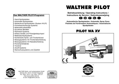
<strong>PILOT</strong> <strong>WA</strong> <strong>XV</strong>
<strong>PILOT</strong> <strong>WA</strong> <strong>XV</strong><br />
Stand: April 2008<br />
Reparatursets<br />
Maintenance kits<br />
Kits de réparation<br />
Reparatiesets<br />
<strong>PILOT</strong> <strong>WA</strong> <strong>XV</strong>-ND<br />
V 16 115 03 . . 3 (<strong>WA</strong> <strong>XV</strong> )<br />
V 16 116 03 . . 3 (<strong>WA</strong> <strong>XV</strong> ziehbar, needle-pull<br />
à tirette, met trekker)<br />
V 16 117 03 . . 3 (<strong>WA</strong> <strong>XV</strong>-ND)<br />
45
EG-Konformitätserklärung<br />
Wir, der Gerätehersteller, erklären in alleiniger Verantwortung, daß das Produkt in<br />
der untenstehenden Beschreibung den einschlägigen grundlegenden Sicherheits- und<br />
Gesundheitsanforderungen entspricht. Bei einer nicht mit uns abgestimmten Änderung an<br />
dem Gerät oder bei einer unsachgemäßen Verwendung verliert diese Erklärung ihre<br />
Gültigkeit.<br />
Hersteller <strong>WA</strong>LTHER Spritz-und Lackiersysteme GmbH<br />
Kärntner Str. 18-30<br />
D-42327 Wuppertal<br />
Tel.: 0202 / 787-0<br />
Fax: 0202 / 787-217<br />
www.walther-pilot.de • Email: info@walther-pilot.de<br />
Typenbezeichnung Automatische Spritzpistolen <strong>PILOT</strong> <strong>WA</strong> <strong>XV</strong><br />
<strong>WA</strong> <strong>XV</strong> V 20 660<br />
<strong>WA</strong> <strong>XV</strong> ziehbar V 20 664<br />
<strong>WA</strong> <strong>XV</strong>-ND (HVLP System)<br />
Verwendungszweck Verarbeitung spritzbarer Materialien<br />
Angewandte Normen und Richtlinien<br />
EG-Maschinenrichtlinien 98 / 37 EG<br />
94 / 9 EG (ATEX Richtlinien)<br />
DIN EN 12100 Teil 1<br />
DIN EN 12100 Teil 2<br />
DIN EN 1127-1<br />
Spezifikation im Sinne der Richtlinie 94 / 9 / EG<br />
V 20 672<br />
Kategorie 2 Gerätebezeichnung II 2 G c T 5<br />
Tech.File,Ref.:<br />
2411<br />
Besondere Hinweise :<br />
Das Produkt ist zum Einbau in ein anderes Gerät bestimmt. Die Inbetriebnahme ist so<br />
lange untersagt, bis die Konformität des Endproduktes mit der Richtlinie 98 / 37 / EG<br />
festgestellt ist.<br />
Wuppertal,den 7. Juli 2003<br />
i.V.<br />
Name: Torsten Bröker<br />
Stellung im Betrieb: Leiter der Konstruktion und Entwicklung<br />
Diese Erklärung ist keine Zusicherung von Eigenschaften im Sinne der Produkthaftung. Die Sicherheitshinweise der<br />
Produktdokumentation sind zu beachten.<br />
Declaration of CE-Conformity<br />
We, the manufacturers of the equipment, hereby declare under our sole responsibility<br />
that the product(s) described below conform to the essential safety requirements. This<br />
declaration will be rendered invalid if any changes are made to the equipment without<br />
prior consultation with us.<br />
Manufacturer <strong>WA</strong>LTHER Spritz-und Lackiersysteme GmbH<br />
Kärntner Str. 18-30<br />
D-42327 Wuppertal<br />
Tel.: 0202 / 787-0<br />
Fax: 0202 / 787-217<br />
www.walther-pilot.de • Email: info@walther-pilot.de<br />
Type Designation Automatic Spray Gun <strong>PILOT</strong> <strong>WA</strong> <strong>XV</strong><br />
<strong>WA</strong> <strong>XV</strong> V 20 660<br />
<strong>WA</strong> <strong>XV</strong> needle-pull V 20 664<br />
<strong>WA</strong> <strong>XV</strong>-ND (System HVLP) V 20 672<br />
Intended purpose Processing of sprayable media<br />
Applied Standards and Directives<br />
EU-Machinery Directive 98 / 37 CE<br />
94 / 9 EC (ATEX Directives)<br />
DIN EN 12100 Part 1<br />
DIN EN 12100 Part 2<br />
DIN EN 1127-1<br />
Specification according 94 / 9 / CE<br />
Category 2 Part marking II 2 G c T 5<br />
Tech.File,Ref.:<br />
2411<br />
Special remarks :<br />
The named product is intended for installation in other equipment. Commissioning is pro-<br />
hibited until such time as the end product has been proved to conform to the provision of<br />
the Directives 98 / 37 / CE.<br />
Wuppertal, the 7th of July 2003<br />
i.V.<br />
Name: Torsten Bröker<br />
Position: Manager, Design and Development<br />
This Declaration does not give assurance of properties in the sense of product liability. The safety instructions provided<br />
in the product documentation must be observed at all times.
Déclaration de conformité CE<br />
En tant que fabricant de cet appareil, nous déclarons en toute responsabilité que le<br />
produit décrit ci-dessous est conforme aux exigences de sécurité et de protection<br />
de la santé actuellement en vigueur. Toute modification sans autorisation de notre part ou<br />
utilisation inadéquate de l'appareil, annulent la validité de cette déclaration.<br />
Fabricant <strong>WA</strong>LTHER Spritz-und Lackiersysteme GmbH<br />
Kärntner Str. 18-30<br />
D-42327 Wuppertal<br />
Tel.: 0202 / 787-0<br />
Fax: 0202 / 787-217<br />
www.walther-pilot.de • Email: info@walther-pilot.de<br />
Dénomination du<br />
modèle<br />
Wuppertal, le 7 juillet 2003<br />
i.V.<br />
Pistolet automatique de pulver. <strong>PILOT</strong> <strong>WA</strong> <strong>XV</strong><br />
<strong>WA</strong> <strong>XV</strong> V 20 660<br />
<strong>WA</strong> <strong>XV</strong> à tirette V 20 664<br />
<strong>WA</strong> <strong>XV</strong>-ND (Système HVLP) V 20 672<br />
Utilisation Application de matières pulvérisables<br />
Normes et directives appliquées<br />
Directive UE sur les machines 98 / 37 UE<br />
94 / 9 EG (directives ATEX)<br />
DIN EN 12100 1 ère partie<br />
DIN EN 12100 2 ème partie<br />
DIN EN 1127-1<br />
Normes et directives appliquées<br />
Catégorie 2<br />
désignation de l'ap-<br />
pareil<br />
II 2 G c T 5<br />
Nom: Torsten Bröker<br />
Position dans l'entreprise: chef de l'exécution et du développement<br />
Tech.File,Ref.:<br />
2411<br />
Indications particulières:<br />
Le produit est conçu pour être intégré à un autre équipement. La mise en service n'est<br />
pas autorisée avant l'établissement de la conformité du produit final avec la directive<br />
98 / 37 / UE.<br />
Cette déclaration ne constitue pas un engagement de responsabilité dans le sens de la garantie du produit. Les consignes<br />
de sécurité contenues dans les instructions de service devront être respectées.<br />
EG-conformiteitsverklaring<br />
De fabrikant verklaart onder geheel eigen verantwoording dat het hierna beschreven<br />
product aan de algemeen aanvaarde veiligheids- en gezondheidsvoorschriften voldoet. Bij<br />
een niet met ons besproken wijziging aan het hierna beschreven product<br />
of bij oneigenlijk gebruik verliest deze verklaring haar geldigheid.<br />
Fabrikant <strong>WA</strong>LTHER Spritz-und Lackiersysteme GmbH<br />
Kärntner Str. 18-30<br />
D-42327 Wuppertal<br />
Tel.: 0202 / 787-0<br />
Fax: 0202 / 787-217<br />
www.walther-pilot.de • Email: info@walther-pilot.de<br />
Typekentekening Automatisch spuitpistool <strong>PILOT</strong> <strong>WA</strong> <strong>XV</strong><br />
<strong>WA</strong> <strong>XV</strong> V 20 660<br />
<strong>WA</strong> <strong>XV</strong> met trekker V 20 664<br />
<strong>WA</strong> <strong>XV</strong>-ND (HVLP-systeem) V 20 672<br />
Doelmatig gebruik verwerking van verstuifbare stoffen<br />
Toegepaste normen en richtlijnen<br />
EG-richtlijnen voor machines 98 / 37 EG<br />
94/9 EG (ATEX richtlijnen)<br />
DIN EN 12100 Deel 1<br />
DIN EN 12100 Deel 2<br />
DIN EN 1127-1<br />
Specificatie overeenkomstig richtlijn 94 / 9 / EG<br />
Categorie 2 Typenummer II 2 G c T 5<br />
Tech.File,Ref.:<br />
2411<br />
NB:<br />
Het product moet worden ingebouwd in een ander apparaat. De ingebruikname is niet<br />
geoorloofd, totdat de conformiteit van het eindproduct met de richtlijn 98 / 37 / EG is vastgesteld.<br />
Wuppertal, 7 juli 2003<br />
i.V.<br />
Naam: Torsten Bröker<br />
Positie: Manager Constructie en Ontwikkeling<br />
Deze verklaring is geen garantie en kan derhalve niet worden gebruikt bij kwesties m.b.t. aansprakelijkheid.<br />
Raadpleeg s.v.p. de veiligheidsvoorschriften in de productdocumentatie.
Dichiarazione di conformità CE<br />
Noi, il costruttore, dichiariamo sotto la nostra esclusiva responsabilità che il prodotto<br />
qui di seguito descritto corrisponde ai requisiti di sicurezza e di salute essenziali in<br />
materia. In caso di modifica del prodotto non concordata con noi o in caso di uso improprio,<br />
la presente dichiarazione cessa di essere valida.<br />
Costruttore <strong>WA</strong>LTHER Spritz- und Lackiersysteme GmbH<br />
Kärntner Str. 18-30<br />
D-42327 Wuppertal<br />
Telefono: 0202 / 787-0<br />
Fax: 0202 / 787-217<br />
www.walther-pilot.de • E-mail: info@walther-pilot.de<br />
Identificazione<br />
del tipo<br />
Wuppertal, il 7 luglio 2003<br />
per delega<br />
Pistole a spruzzo automatiche <strong>PILOT</strong> <strong>WA</strong> <strong>XV</strong><br />
<strong>WA</strong> <strong>XV</strong> V 20 660<br />
<strong>WA</strong> <strong>XV</strong> estraibile V 20.664<br />
<strong>WA</strong> <strong>XV</strong>-ND (sistema HVLP) V 20.672<br />
Uso previsto Applicazione di materiali spruzzabili<br />
Norme e direttive applicate<br />
Direttive macchine 98 / 37 CE<br />
94 / 9 CE (direttive ATEX)<br />
DIN EN 12100 parte 1<br />
DIN EN 12100 parte 2<br />
DIN EN 1127-1<br />
Specifica secondo la direttiva 94 / 9 / CE<br />
Categoria 2<br />
Designazione<br />
dell’apparecchio<br />
II 2 G c T 5<br />
Nome: Torsten Bröker<br />
Posizione aziendale: Dirigente del reparto progettazione e sviluppo<br />
File tecn., rif.:<br />
2411<br />
Indicazioni speciali:<br />
Il prodotto è previsto per essere incorporato in un altro apparecchio. La messa in servizio non<br />
è consentita finché non sia stata constatata la conformità del prodotto finale con la direttiva<br />
98 / 37 / CE.<br />
La presente dichiarazione non è una garanzia di caratteristiche nel senso della responsabilità del prodotto.<br />
Osservare rigorosamente le norme di sicurezza della documentazione del prodotto.
Ersatzteilliste für Modell<br />
<strong>PILOT</strong> <strong>WA</strong> <strong>XV</strong><br />
Pos. Ersatzteil-Nr. Bezeichnung<br />
Nr.<br />
1 V 01 101 03 000 Luftkopfmutter<br />
2 wahlweise 6-Loch-Luftkopf<br />
V 01 101 02 . . 6*<br />
weitere Luftköpfe auf Anfrage<br />
3 wahlweise Materialdüse<br />
V 01 101 07 . . 3*<br />
4 V 11 301 02 000 Luftverteilerring<br />
5a V 20 660 02 000 Pistolenvorsatz<br />
5b V 20 661 02 000 Pistolenvorsatz<br />
(nur bei Umlauf)<br />
6 V 09 001 72 000 Nadelpackung<br />
7 V 20 660 05 000 Gegenbuchse<br />
8 V 20 660 06 000 Druckfeder<br />
9 V 20 660 07 000 Stopfbuchse<br />
10 V 09 001 67 000 Dichtung<br />
11 V 20 660 01 000 Pistolenkörper<br />
12 V 20 660 20 000 Breitstrahlregelung<br />
kompl.<br />
13 V 20 660 08 000 Zylinderschraube<br />
14 V 00 101 01 000 Doppelnippel<br />
15 V 09 002 07 000 Usit-Ring<br />
16 V 20 660 04 003 Sechskantmutter<br />
17 V 20 201 02 000 Dichtschraube<br />
18 V 09 102 02 000 O-Ring<br />
19 V 20 660 42 000 Abdeckkappe<br />
20 V 20 660 32 000 Manschette<br />
21 V 09 102 11 000 O-Ring<br />
22 V 20 660 33 000 Verschlußschraube<br />
23 V 09 102 09 000 O-Ring<br />
24 V 20 660 31 000 Steuerkolben<br />
25 V 20 651 06 000 Manschette<br />
26 V 20 660 34 000 Stützscheibe<br />
27 wahlweise Materialnadel<br />
V 20 660 51 . .3*<br />
28 V 10 506 02 000 Nadelmutter<br />
29 V 20 651 07 000 Nadelfeder<br />
30 V 20 660 36 000 Kolbenschraube<br />
31 V 20 606 11 000 Kolbenfeder<br />
32 V 20 660 35 000 Federteller<br />
33 V 20 660 37 000 Federbuchse<br />
34 V 20 660 38 000 Federstift<br />
35 V 20 660 39 120 Regelschraube<br />
Abweichende Ersatzteile von<br />
<strong>PILOT</strong> <strong>WA</strong> <strong>XV</strong><br />
Ersatzteile <strong>PILOT</strong> <strong>WA</strong> <strong>XV</strong> ziehbar<br />
Typ V 20 664<br />
Pos. Ersatzteil-Nr. Bezeichnung<br />
Nr.<br />
27-35 Bauteile entfallen<br />
36 V 20 664 05 000 Kolbenschraube<br />
37 wahlweise Materialnadel<br />
V 20 664 43 . . 3*<br />
38 V 20 664 02 000 Anschlagbolzen<br />
39 V 20 206 04 000 Nadelfeder<br />
40 V 20 664 04 000 Regelschraube<br />
41 V 20 664 03 000 Scheibe<br />
42 V 20 679 85 000 U-Scheibe<br />
43 V 20 679 84 000 Fächerscheibe<br />
44 V 20 660 41 684 Zylinderschraube<br />
Ersatzteile <strong>PILOT</strong> <strong>WA</strong> <strong>XV</strong>-ND<br />
(HVLP System) Typ V 20 672<br />
2 wahlweise Luftkopf für Düsen<br />
V 01 101 86 086* 0,3 - 2,0 mm ø<br />
V 01 101 86 256* 2,5 - 3,0 mm ø<br />
3 V 01 101 85 . . 3* Materialdüse<br />
11 V 20 671 01 000 Pistolenkörper<br />
20 V 20 671 32 000 Manschette<br />
30 V 20 664 05 000 Kolbenschraube<br />
37 wahlweise Materialnadel<br />
V 20 664 43 033 0,3 ø für 0,3-Düse<br />
V 20 664 43 053 0,5 ø für 0,5-Düse<br />
für Düsen<br />
V 20 664 43 083* 0,8 - 1,5 mm ø<br />
V 20 664 43 123* 1,8 - 2,0 mm ø<br />
V 20 664 43 253* 2,5 - 3,0 mm ø<br />
38 V 20 664 02 000 Anschlagbolzen<br />
39 V 20 206 04 000 Nadelfeder<br />
40 V 20 664 04 000 Regelschraube<br />
41 V 20 664 03 000 Scheibe<br />
42 V 20 679 85 000 U-Scheibe<br />
43 V 20 679 84 000 Fächerscheibe<br />
44 V 20 660 41 684 Zylinderschraube<br />
45 V 20 671 40 000 Mittenluftregelung<br />
* Bei Ersatzteillieferung bitte die entspechenden Größen<br />
angeben. Wir empfehlen, alle fettgedruckten Ersatzteile<br />
(Verschleißteile) auf Lager zu halten.<br />
Inhaltsverzeichnis<br />
1 Allgemeines<br />
1.1 Kennzeichnung des Modells<br />
1.2 Bestimmungsgemäße Verwendung<br />
1.3 Sachwidrige Verwendung<br />
2 Technische Beschreibung<br />
3 Sicherheitshinweise<br />
3.1 Kennzeichnung der Sicherheitshinweise<br />
3.2 Allgemeine Sicherheitshinweise<br />
4 Montage<br />
4.1 Spritzpistole befestigen<br />
4.2 Versorgungsleitungen anschließen<br />
5 Bedienung<br />
5.1 Sicherheitshinweise<br />
5.2 Inbetrieb- und Außerbetriebsetzen<br />
5.3 Spritzbildprobe erzeugen<br />
5.4 Spritzbild verändern<br />
5.5 Spritzpistole umrüsten<br />
6 Reinigung und Wartung<br />
6.1 Sicherheitshinweise<br />
6.2 Grundreinigung<br />
6.3 Routinereinigung<br />
7 Instandsetzung<br />
7.1 Undichte Nadelpackung austauschen<br />
7.2 Materialdüse, -nadel, Federn und Dichtungen austauschen<br />
8 Fehlersuche und -beseitigung<br />
9 Entsorgung<br />
10 Technische Daten
1 Allgemeines<br />
1.1 Kennzeichnung des Modells<br />
Modell: Automatische Spritzpistole <strong>PILOT</strong> <strong>WA</strong> <strong>XV</strong><br />
Typen: <strong>WA</strong> <strong>XV</strong> V 20 660<br />
<strong>WA</strong> <strong>XV</strong> ziehbar V 20 664<br />
<strong>WA</strong> <strong>XV</strong>-ND (HVLP System) V 20 672<br />
Hersteller: <strong>WA</strong>LTHER Spritz-und Lackiersysteme GmbH<br />
Kärntner Str. 18-30<br />
D-42327 Wuppertal<br />
Tel.: 0202 / 787-0<br />
Fax: 0202 / 787-217<br />
www.walther-pilot.de • Email: info@walther-pilot.de<br />
1.2 Bestimmungsgemäße Verwendung<br />
Die automatische Spritzpistole <strong>PILOT</strong> <strong>WA</strong> <strong>XV</strong> / ziehbar / -ND dient ausschließlich der<br />
Verarbeitung spritzbarer Medien. Da sämtliche materialführenden Teile aus Edelstahl<br />
gefertigt sind, können auch wasserhaltige bzw. aggressive Materialien verspritzt werden,<br />
wie z.B.:<br />
• Lacke und Farben<br />
• Fette, Öle und Korrosionsschutzmittel<br />
• Kleber<br />
• Keramikglasuren<br />
• Beizen<br />
Sind die Materialien, die Sie verspritzen wollen, hier nicht aufgeführt, wenden Sie sich<br />
bitte an <strong>WA</strong>LTHER Spritz- und Lackiersysteme GmbH, Wuppertal.<br />
Die spritzbaren Materialien dürfen lediglich auf Werkstücke bzw. Gegenstände aufgetragen<br />
werden.<br />
Die Temperatur des Spritzmaterials darf 80°C grundsätzlich nicht überschreiten.<br />
Die Modelle der Baureihe <strong>PILOT</strong> <strong>WA</strong> <strong>XV</strong> sind keine handgeführten Spritzpistolen und<br />
müssen deshalb an einer geeigneten Halterung befestigt werden.<br />
Die bestimmungsgemäße Verwendung schließt auch ein, dass alle Hinweise und An-<br />
gaben der vorliegenden <strong>Betriebsanleitung</strong> gelesen, verstanden und beachtet werden.<br />
Das Gerät erfüllt die Explosionsschutz-Forderungen der Richtlinie 94 / 9 EG (ATEX<br />
100a) für die auf dem Typenschild angegebene Explosionsgruppe, Gerätekategorie,<br />
und Temperaturklasse. Beim Betreiben des Gerätes sind die Vorgaben dieser Betriebs-<br />
anleitung unbedingt einzuhalten. Die vorgeschriebenen Inspektions- und Wartungs-<br />
intervalle sind einzuhalten. Die Angaben auf den Geräteschildern bzw. die Angaben in<br />
dem Kapitel technische Daten sind unbedingt einzuhalten und dürfen nicht überschritten<br />
werden. Eine Überlastung des Gerätes muss ausgeschlossen sein.<br />
Das Gerät darf in explosionsgefährdeten Bereichen nur nach Maßgabe der zuständigen<br />
Aufsichtsbehörde eingesetzt werden.<br />
Der zuständigen Aufsichtsbehörde bzw. dem Betreiber obliegt die Festle-<br />
gung der Explosionsgefährdung (Zoneneinteilung).<br />
Es ist betreiberseitig zu prüfen und sicherzustellen, daß alle technischen Daten und<br />
die Kennzeichnung gemäß ATEX mit den notwendigen Vorgaben übereinstimmen.<br />
Anwendungen, bei denen der Ausfall des Gerätes zu einer Personengefährdung führen<br />
könnten, sind betreiberseitig entsprechende Sicherheitsmaßnahmen vorzusehen.<br />
Falls im Betrieb Auffälligkeiten erkannt werden, muss das Gerät sofort stillgesetzt<br />
werden und es ist mit <strong>WA</strong>LTHER-<strong>PILOT</strong> Rücksprache zu halten.<br />
Erdung / Potentialausgleich<br />
Es muss sichergestellt werden, dass die Spritzpistole separat oder in Verbindung mit<br />
dem Gerät auf dem sie aufgebaut ist, ausreichend geerdet ist (maximaler<br />
Wiederstand 10 6 Ω).<br />
1.3 Sachwidrige Verwendung<br />
Die Spritzpistole darf nicht anders verwendet werden, als es im Abschnitt 1.2 Be<br />
-stimmungsgemäße Verwendung geschrieben steht. Jede andere Verwendung ist<br />
sachwidrig. Zur sachwidrigen Verwendung gehören z.B.:<br />
• das Verspritzen von Materialien auf Personen und Tiere<br />
• das Verspritzen von flüssigem Stickstoff.<br />
2 Technische Beschreibung<br />
Die Modelle der Baureihe <strong>PILOT</strong>-Serie <strong>WA</strong> <strong>XV</strong> arbeiten vollautomatisch über eine<br />
Druckluftsteuerung und werden über ein 3/2-Wege-Steuerventil angesteuert. Dazu<br />
können Hand-, Fuß- oder Magnetventile eingesetzt werden.<br />
Wird das 3/2-Wege-Steuerventil betätigt, tritt die für die Steuerung erforderliche<br />
Druckluft in den Zylinderraum der Spritzpistole ein und öffnet den Zerstäuberluft-<br />
kanal und anschließend die Materialzufuhr.<br />
Wird die Steuerluft durch das 3/2-Wege-Steuerventil wieder unterbrochen, entweicht<br />
zunächst die im Zylinder befindliche Druckluft. Der Federdruck der Kolben-<br />
feder drückt anschließend die Materialnadel in ihre Ausgangsstellung zurück und<br />
verschließt die Material- und Zerstäuberluftzufuhr.<br />
Die Material-Durchflussmenge und die Form des Spritzstrahls (flach / breit / rund)<br />
werden mit Regelschrauben an der Pistole eingestellt.<br />
Der Materialdurchfluss des Modells <strong>PILOT</strong> <strong>WA</strong> <strong>XV</strong> ziehbar kann von Hand geöffnet<br />
und dadurch z. B. eine verstopfte Materialdüse gereinigt werden.<br />
Das Modell <strong>PILOT</strong> <strong>WA</strong> <strong>XV</strong>-ND ist eine Niederdruckpistole und arbeitet mit einem<br />
Spritzdruck von 0,7 bar bei einem Eingangsdruck von 3,5 bar.<br />
Der Pistolenvorsatz mit Doppelanschluss für die Materialzufuhr kann die <strong>PILOT</strong> <strong>WA</strong><br />
<strong>XV</strong> - Spritzpistole in eine Umlaufanlage eingebunden werden. Hiermit können mehrere<br />
Spritzpistolen gleichzeitig durch die ringförmig angeordnete Umlaufleitung mit<br />
dem Spritzmaterial versorgt werden.<br />
Die Spritzpistole kann an Materialdruckgefäße und Pumpensysteme angeschlossen<br />
werden<br />
2 3
3 Sicherheitshinweise<br />
3.1 Kennzeichnung der Sicherheitshinweise<br />
Warnung<br />
Das Piktogramm und die Dringlichkeitsstufe „Warnung“ kennzeichnen eine mögliche<br />
Gefahr für Personen. Mögliche Folgen: schwere oder leichte Verletzungen.<br />
Achtung<br />
Das Piktogramm und die Dringlichkeitsstufe „Achtung“ kennzeichnen eine mögliche<br />
Gefahr für Sachwerte. Mögliche Folgen: Beschädigung von Sachen.<br />
Hinweis<br />
Das Piktogramm und die Dringlichkeitsstufe „Hinweis“ kennzeichnen zusätzliche<br />
Informationen für das sichere und effiziente Arbeiten mit der Spritzpistole.<br />
3.2 Allgemeine Sicherheitshinweise<br />
• Die einschlägigen Unfallverhütungsvorschriften sowie die sonstigen anerkannten<br />
sicherheitstechnischen und arbeitsmedizinischen Regeln sind einzuhalten.<br />
• Benutzen Sie die Spritzpistole nur in gut belüfteten Räumen. Im Arbeitsbereich ist<br />
Feuer, offenes Licht und Rauchen verboten. Beim Verspritzen leichtentzündlicher<br />
Materialien (z. B. Lacke, Kleber, Reinigungsmittel usw.) besteht erhöhte Gesundheits-,<br />
Explosions- und Brandgefahr.<br />
• Es muss sichergestellt werden, dass die Spritzpistole separat oder in Verbindung mit<br />
dem Gerät auf dem sie aufgebaut ist, ausreichend geerdet ist (max. Widerstand 10 6 Ω).<br />
• Schalten Sie vor jeder Wartung und Instandsetzung die Luft- und Materialzufuhr zur<br />
Spritzpistole drucklos - Verletzungsgefahr.<br />
• Halten Sie beim Verspritzen von Materialien keine Hände oder andere Körperteile vor<br />
die unter Druck stehende Düse der Spritzpistole - Verletzungsgefahr.<br />
• Richten Sie die Spritzpistole nicht auf Personen und Tiere - Verletzungsgefahr.<br />
• Beachten Sie die Verarbeitungs- und Sicherheitshinweise der Hersteller von Spritz-<br />
material und Reinigungsmittel. Insbesondere aggressive und ätzende Materialien können<br />
gesundheitliche Schäden verursachen.<br />
• Die partikelführende Abluft ist vom Arbeitsbereich und Betriebspersonal fernzuhalten.<br />
Tragen Sie dennoch vorschriftsgemäßen Atemschutz und vorschriftsgemäße Arbeits-<br />
kleidung, wenn Sie mit der Spritzpistole Materialien verarbeiten. Umherschwebende<br />
Partikel gefährden Ihre Gesundheit.<br />
• Tragen Sie im Arbeitsbereich der Spritzpistole einen Gehörschutz. Der erzeugte<br />
Schallpegel der Spritzpistole beträgt ca. 86 dB (A).<br />
• Achten Sie stets darauf, daß bei Inbetriebnahme, insbesondere nach Montage- und<br />
Wartungsarbeiten alle Muttern und Schrauben fest angezogen sind.<br />
• Verwenden Sie nur Original-Ersatzteile, da <strong>WA</strong>LTHER nur für diese eine sichere und<br />
einwandfreie Funktion garantieren kann.<br />
Bei Nachfragen zur gefahrlosen Benutzung der Spritzpistole sowie der darin verwendeten<br />
Materialien, wenden Sie sich bitte an <strong>WA</strong>LTHER Spritz- und Lackiersysteme GmbH,<br />
D-42327 Wuppertal.<br />
4 Montage<br />
Die Spritzpistole ist werkseitig komplett montiert. Bevor Sie die Spritzpistole in<br />
Betrieb setzen können, sind die folgenden Tätigkeiten durchzuführen:<br />
4.1 Spritzpistole befestigen<br />
Befestigen Sie die Spritzpistole an einer geeigneten, standsicheren Halterung, wie<br />
im folgenden Beispiel beschrieben:<br />
4.2 Versorgungsleitungen anschließen<br />
Warnung<br />
Achten Sie darauf, das die Anschlüsse der Steuer- und Zerstäuberluft nicht vertauscht<br />
werden - Verletzungsgefahr.<br />
1. Schrauben Sie die Versorgungsleitung<br />
• der Zerstäuberluft an den mit “SPRITZ-<br />
LUFT” gekennzeichneten Anschluss der<br />
<strong>PILOT</strong> <strong>WA</strong> <strong>XV</strong><br />
-ND<br />
STEUERLUFT<br />
SPRITZLUFT<br />
1. Schieben Sie die Spritzpistole mit der Bohr-<br />
ung 12 mm ø auf das Profil der Halte-<br />
rung.<br />
2. Richten Sie die Spritzpistole auf das zu be-<br />
spritzende Werkstück aus. Dazu können<br />
Sie die Spritzpistole auf der Längsachse<br />
des Profils verschieben und drehen.<br />
3. Ziehen Sie die Zylinderschraube mit<br />
einem 8er Innensechskant-Schlüssel fest.<br />
Spritzpistole (G 1/4”).<br />
• der Steuerluft an mit “STEUERLUFT” ge-<br />
kennzeichneten Anschluss der<br />
Spritzpistole<br />
(G 1/4”).<br />
• der Materialzufuhr an den Anschluss <br />
der Spritzpistole (G 3/8”).<br />
2. Ziehen Sie die drei Sechskantmuttern <br />
der Anschlüsse mit der Werkzeugschlüssel<br />
fest.<br />
Die Spritzpistole ist nun vollständig montiert und kann in Betrieb gesetzt werden.<br />
4 5
6<br />
5 Bedienung<br />
5.1 Sicherheitshinweise<br />
Beachten Sie bei der Bedienung der Spritzpistole insbesondere die nachfolgenden<br />
Sicherheitshinweise!<br />
• Tragen Sie vorschriftsmäßigen Atemschutz und Arbeitskleidung, wenn Sie mit der<br />
Spritzpistole Materialien verspritzen. Umherschwebende Partikel gefährden Ihre<br />
Gesundheit.<br />
• Tragen Sie im Arbeitsbereich der Spritzpistole einen Gehörschutz. Der erzeugte<br />
Schallpegel der Spritzpistole von ca. 86 dB (A) kann einen Gehörschaden verursachen.<br />
• Im Arbeitsbereich ist Feuer, offenes Licht und Rauchen verboten. Beim Verspritzen<br />
leicht entzündbarer Materialien (z. B. Lacke, Kleber) besteht erhöhte Explosions- und<br />
Brandgefahr.<br />
5.2 Inbetrieb- und Außerbetriebsetzen<br />
Bevor Sie die Spritzpistole in Betrieb setzen können, müssen folgende Voraussetzun-<br />
gen erfüllt sein:<br />
• Der Zerstäuberluftdruck muss an der Spritzpistole anstehen.<br />
• Der Materialdruck muss an der Spritzpistole anstehen.<br />
• Der Steuerluftdruck muss an der Spriztpistole anstehen.<br />
Achtung<br />
Der Materialdruck darf nicht höher eingestellt sein als<br />
• 10 bar bei <strong>WA</strong> <strong>XV</strong>,<br />
• 15 bar bei <strong>WA</strong> <strong>XV</strong> ziehbar / <strong>WA</strong> <strong>XV</strong>-ND<br />
da sonst kein funktionssicherer Betrieb der Spritzpistole gewährleistet ist.<br />
Stellen Sie den Steuerluftdruck auf<br />
• maximal 8 bar,<br />
damit die Spritzpistole in Betrieb gesetzt werden kann.<br />
Sie können die Spritzpistole in und außer Betrieb setzen, indem Sie das 3/2-Wege-<br />
Steuerventil betätigen (siehe <strong>Betriebsanleitung</strong> des Anlagenherstellers).<br />
Warnung<br />
Die Spritzpistole muß nach Arbeitsende immer drucklos geschaltet werden. Die unter<br />
Druck stehenden Leitungen können platzen und nahestehende Personen durch das<br />
ausströmende Material verletzen.<br />
5.3 Spritzbildprobe erzeugen<br />
Eine Spritzbildprobe sollte immer dann erzeugt werden, wenn:<br />
• die Spritzpistole zum ersten Mal in Betrieb gesetzt wird.<br />
• das Spritzmaterial ausgetauscht wird.<br />
• die Pistole zur Wartung oder Instandsetzung zerlegt wurde.<br />
Die Spritzbildprobe kann auf ein Probewerkstück, Blech, Pappe oder Papier abgegeben<br />
werden.<br />
Warnung<br />
Halten Sie beim Verspritzen von Materialien keine Hände oder andere Körperteile<br />
vor die unter Druck stehende Düse der Spritzpistole -Verletzungsgefahr.<br />
Warnung<br />
Achten Sie beim Inbetriebsetzen der Spritzpistole darauf, daß sich keine Person<br />
im Spritzbereich befindet - Verletzungsgefahr.<br />
1. Setzen Sie die Spritzpistole in Betrieb, um eine Spritzbildprobe zu erzeugen<br />
(siehe 5.2 Inbetrieb- und Außerbetriebsetzen).<br />
2. Kontrollieren Sie die Spritzbildprobe und verändern Sie ggf.die Einstellungen an<br />
der Spritzpistole (siehe 5.4 Spritzbild verändern).<br />
5.4 Spritzbild verändern<br />
Sie können an den Spritzpistolen der Baureihe <strong>PILOT</strong> <strong>WA</strong> <strong>XV</strong> / <strong>WA</strong> <strong>XV</strong> ziehbar /<br />
<strong>WA</strong> <strong>XV</strong>-ND durch die folgenden Einstellungen das Spritzbild verändern.<br />
Breit- bzw. Flachstrahl einstellen<br />
1. Lösen Sie die geriffelte Luftkopfmutter <br />
ein wenig.<br />
Breit- / Flachstrahl bzw. Rundstrahl einstellen<br />
2. Drehen Sie den Luftkopf auf:<br />
• eine senkrechte Stellung der<br />
Luftkopf-<br />
Hörner = Flachstrahl<br />
• eine waagerechte Stellung der<br />
Luftkopf-<br />
Hörner = Breitstrahl<br />
3. Schrauben Sie die Luftkopfmutter fest.<br />
4. Lösen Sie die Kontermutter mit einem<br />
Schraubenschlüssel SW 11.<br />
5. Drehen Sie die Feineinstellschraube <br />
• in Richtung -, um eine rundere Spritz-<br />
strahlform zu erhalten.<br />
• in Richtung +, um eine beitere Spritz-<br />
strahlform zu erhalten.<br />
6. Ziehen Sie die Kontermutter wieder an,<br />
dadurch wird die eingestellte Spritzstrahl-<br />
form gesichert.<br />
7
Mittenluftregulierung (nur <strong>PILOT</strong> <strong>WA</strong> <strong>XV</strong>-ND)<br />
<br />
Die Einstellschraube dient zur Regulierung der Mitten-<br />
luft.<br />
<br />
Materialdurchflussmenge einstellen<br />
1. Drehen Sie die Regelschraube der Materialzufuhr aus der Grundstellung<br />
(= Kerbe an der Federbuchse)<br />
• in Richtung -, um den Materialdurchfluss zu verringern.<br />
• in Richtung +, um den Materialdurchfluss zu erhöhen.<br />
Materialdruck regulieren<br />
Diese Einstellung können Sie nur an der Pumpe oder am Druckbehälter vornehmen.<br />
Beachten Sie dabei die Anweisungen und Sicherheitshinweise des Herstellers.<br />
Zerstäuberluftdruck regulieren<br />
Der Zerstäuberluftdruck wird am Druckluft-Reduzierventil der Kompressoranlage eingestellt.<br />
Beachten Sie die Anweisungen und Sicherheitshinweise des Herstellers.<br />
Wenn Sie das Spritzbild über die bereits erwähnten Möglichkeiten hinaus verändern<br />
wollen, muß die Spritzpistole umgerüstet werden (siehe 5.5 Spritzpistole umrüsten).<br />
<strong>WA</strong>LTHER bietet dazu eine Vielzahl unterschiedlicher Luftkopf-/ Materialdüse-/ Nadel-<br />
Kombinationen an.<br />
Mängel eines Spritzbildes beheben<br />
Die folgende Tabelle zeigt Ihnen, mit welchen Einstellungen Sie das Spritzbild beeinflussen<br />
können.<br />
angestrebtes Spritzergebnis<br />
Spritzbildprobe Abweichung erforderliche Einstellung<br />
5.5 Spritzpistole umrüsten<br />
Die zum Spritzmaterial passende Luftkopf-/ Materialdüse-/ Nadel-Kombination bildet<br />
eine aufeinander abgestimmte Einheit - die Düseneinlage. Tauschen Sie immer<br />
die komplette Düseneinlage aus, damit die gewünschte Spritzbildqualität erhalten<br />
bleibt.<br />
Warnung<br />
Schalten Sie vor jeder Umrüstung die Steuer- und Zerstäuberluft sowie die<br />
Material- zufuhr zur Spritzpistole drucklos - Verletzungsgefahr.<br />
Luftkopf wechseln<br />
Materialdüse und -nadel wechseln<br />
<strong>WA</strong> <strong>XV</strong> / <strong>WA</strong> <strong>XV</strong>-ND:<br />
1. Schrauben Sie die geriffelte<br />
Luftkopfmutter ab.<br />
2. Ziehen Sie den Luftkopf vom<br />
Pistolenvorsatz herunter.<br />
3. Setzen Sie den gewünschten Luftkopf auf<br />
den Pistolenvorsatz.<br />
4. Schrauben Sie die Luftkopfmutter auf<br />
den Pistolenvorsatz.<br />
1. Schalten Sie die Spritzpistole drucklos<br />
(siehe 5.2 Außerberiebsetzen).<br />
2. Entfernen Sie den Luftkopf (siehe 5.5 Luft-<br />
kopf wechseln).<br />
Spritzbild ist in der Mitte<br />
zu dick<br />
• breitere Spritzstrahlform<br />
einstellen<br />
3. Schrauben Sie die Materialdüse aus<br />
dem Pistolenvorsatz (SW 12).<br />
Spritzbild ist an den • rundere Spritzstrahlform<br />
4. Schrauben Sie die Regelschraube für<br />
Enden zu dick<br />
einstellen<br />
den Materialdurchfluss ab.<br />
Spritzbild ist ziemlich<br />
grobtropfig<br />
Materialauftrag ist in der<br />
• Zerstäuberluftdruck<br />
erhöhen<br />
• Zerstäuberluftdruck<br />
5. Ziehen Sie die beiden Federstifte heraus.<br />
Spritzbildmitte sehr dünn verringern<br />
6. Schrauben Sie die Federbuchse mit<br />
Spritzbild ist in der Mitte<br />
gespalten<br />
• Düsendurchmesser erhöhen<br />
• Zerstäuberluftdruck verringern<br />
• Materialdruck erhöhen<br />
einem Schraubenschlüssel SW 27 ab.<br />
Spritzbild ist sehr ballig<br />
• Materialdruck verringern<br />
• Zerstäuberluftdruck erhöhen<br />
8 9
Die Montage der neuen Düseneinlage sowie der restlichen Bauteile erfolgt in umgekehrter<br />
Reihenfolge.<br />
<strong>WA</strong> <strong>XV</strong> ziehbar / <strong>WA</strong> <strong>XV</strong>-ND:<br />
7. Enfernen Sie die Druckfeder aus dem<br />
Pistolenvorsatz.<br />
8. Ziehen Sie den Kolben mit einer Zange<br />
vorsichtig aus dem Pistolenkörper.<br />
9. Schrauben Sie mit einem Schraubenschlüssel<br />
SW 13 und SW 22 die Kolbenschraube <br />
vom Steuerkolben . Die Materialnadel <br />
liegt nun frei und kann herausgezogen werden.<br />
10. Schrauben Sie nun die beiden Nadelmuttern<br />
ab.<br />
1. Schalten Sie die Spritzpistole drucklos<br />
(siehe 5.2 Außerberiebsetzen).<br />
2. Entfernen Sie den Luftkopf (siehe 5.5 Luftkopf<br />
wechseln).<br />
3. Schrauben Sie die Materialdüse aus dem<br />
Pistolenvorsatz (SW 12).<br />
4. Schrauben Sie die Zylinderschraube ab und<br />
ziehen Sie die Scheibe herunter.<br />
5. Schrauben Sie die Regelschraube für den<br />
Materialdurchfluss ab.<br />
6. Ziehen Sie die Nadelfeder heraus.<br />
7. Ziehen Sie den Kolben inklusive Material-<br />
nadel heraus.<br />
8. Schrauben Sie die Materialnadel aus dem<br />
Anschlagbolzen .<br />
Die Montage der neuen Düseneinlage sowie der restlichen Bauteile erfolgt in umgekehrter<br />
Reihenfolge.<br />
6 Reinigung und Wartung<br />
6.1 Sicherheitshinweise<br />
• Schalten Sie vor jeder Wartung die Steuer- und Zerstäuberluft sowie die Material-<br />
zufuhr zur Spritzpistole drucklos - Verletzungsgefahr.<br />
• Im Arbeitsbereich ist Feuer, offenes Licht und Rauchen verboten. Beim Versprit-<br />
zen leichtentzündlicher Materialien (z. B. Reinigungsmittel) besteht erhöhte Explo-<br />
sions- und Brandgefahr.<br />
• Beachten Sie die Sicherheitshinweise des Reinigungsmittel-Herstellers.<br />
Insbesondere aggressive und ätzende Reinigungsmittel können gesundheitliche<br />
Schäden verursachen.<br />
6.2 Grundreinigung<br />
Damit die Lebensdauer und die Funktion der Spritzpistole lange erhalten bleibt,<br />
muss die Spritzpistole regelmäßig gereinigt und geschmiert werden. Verwenden Sie<br />
zur Reinigung der Spritzpistole nur Reinigungsmittel, die vom Hersteller des Spritz-<br />
materials angegeben werden und die folgenden Bestandteile nicht enthalten:<br />
• halogenierte Kohlenwasserstoffe (z. B. 1,1,1, Trichlorethan, Methylen-Chlorid usw.)<br />
• Säuren und säurehaltige Reinigungsmittel<br />
• regenerierte Lösemittel (sog. Reinigungsverdünnungen)<br />
• Entlackungsmittel.<br />
Die o.g. Bestandteile verursachen an galvanisierten Bauteilen chemische Reaktio-<br />
nen und führen zu Korrosionsschäden.<br />
Für Schäden, die aus einer derartigen Behandlung herrühren, übernimmt<br />
<strong>WA</strong>LTHER <strong>PILOT</strong> keine Gewährleistung.<br />
Reinigen Sie die Spritzpistole<br />
• vor jedem Farb- bzw. Materialwechsel.<br />
• mindestens einmal wöchentlich.<br />
• materialabhängig und je nach Verschmutzungsgrad mehrfach wöchentlich.<br />
Achtung<br />
Legen Sie die Spritzpistole nie in Lösemittel oder ein anderes Reinigungsmittel. Die<br />
einwandfreie Funktion der Spritzpistole kann sonst nicht garantiert werden.<br />
Achtung<br />
Verwenden Sie zur Reinigung keine harten oder spitzen Gegenstände. Präzisions-<br />
teile der Spritzpistole könnten sonst beschädigt werden und das Spritzergebnis verschlechtern.<br />
10 11
1. Zerlegen Sie die Spritzpistole, s. 5.5 Spritzpistole umrüsten.<br />
2. Reinigen Sie den Luftkopf und die Materialdüse mit einem Pinsel und dem Reini-<br />
gungsmittel.<br />
3. Reinigen Sie alle übrigen Bauteile und den Pistolenkörper mit einem Tuch und dem<br />
Reinigungsmittel.<br />
4. Bestreichen Sie folgende Bauteile mit einem dünnen Fettfilm:<br />
• Manschette des Kolbens<br />
• O-Ring des Kolben<br />
• Materialnadel<br />
• Nadelfeder<br />
• Innenraum des Spritzpistolenkörpers<br />
Verwenden Sie dazu ein säurefreies, nicht harzendes Fett und einen Pinsel.<br />
Anschließend wird die Spritzpistole in umgekehrter Reihenfolge zusammmengesetzt.<br />
6.3 Routinereinigung<br />
Bei regelmäßigen Farbwechseln oder (materialabhängig) nach Arbeitsende können Sie<br />
die Spritzpistole auch reinigen, ohne diese dabei zerlegen zu müssen.<br />
Hinweis<br />
Reinigen und schmieren Sie die Spritzpistole dennoch regelmäßig gemäß Abschnitt 6.2<br />
Grundreinigung. Sie erhalten so die sichere Funktion und die Qualität der Spritzpistole.<br />
Bevor Sie die Routinereinigung durchführen können, müssen folgende Vorraussetzung<br />
erfüllt sein:<br />
• Der gesäuberte Materialbehälter wird mit einem geeigneten Reinigungsmittel befüllt.<br />
• Lediglich der Materialdruck muss an der Spritzpistole anstehen. Das Reinigungsmittel<br />
sollte nicht zerstäubt werden.<br />
Um die Spritzpistole zu reinigen, muss die Spritzanlage in Betrieb genommen werden.<br />
1. Setzen Sie die Spritzpistole in Betrieb, (siehe 5.2 Inbetriebsetzen).<br />
2. Setzen Sie die Spritzpistole erst außer Betrieb, wenn diese nur noch klares Reini-<br />
gungsmittel verspritzt.<br />
nur <strong>WA</strong> <strong>XV</strong> ziehbar<br />
<strong>WA</strong> <strong>XV</strong>-ND<br />
Damit nicht die gesamte Spritzanlage in Betrieb<br />
gesetzt werden muss, können Sie die Materialzufuhr<br />
auch von Hand entsperren.<br />
1. Ziehen Sie die Scheibe der Spritzpistole nach<br />
hinten. Die Materialzufuhr wird geöffnet und<br />
Materialkanal und -düse werden gereinigt.<br />
7 Instandsetzung<br />
Warnung<br />
Schalten Sie vor jeder Instandsetzung die Steuer- und Zerstäuberluft sowie die<br />
Materialzufuhr zur Spritzpistole drucklos - Verletzungsgefahr.<br />
7.1 Undichte Nadelpackung austauschen<br />
1. Schalten Sie die Spritzpistole drucklos<br />
(siehe 5.2 Außerberiebsetzen).<br />
2. Ziehen Sie die weiße Abdeckkappe vom<br />
Pistolenkörper.<br />
3. Schrauben Sie die die Sechskantmutter <br />
mit einem Schraubenschlüssel SW 17 ab.<br />
4. Ziehen Sie den Usit-Ring herunter.<br />
5. Ziehen Sie den Pistolenvorsatz vorsichtig<br />
aus dem Pistolenkörper heraus.<br />
6. Entfernen Sie die Dichtung (austauschen,<br />
falls beschädigt).<br />
7. Schrauben sie die Stopfbuchse mit<br />
einem Schraubenschlüssel SW 11 vom<br />
Pistolenvorsatz.<br />
8. Entnehmen Sie die Druckfeder (aus-<br />
tauschen, falls beschädigt) und die Gegen-<br />
buchse aus der Einschrauböffnung.<br />
9. Ziehen Sie die Nadelpackung mit einem<br />
Hilfswerkzeug aus ihrem Sitz. Verwenden<br />
Sie dazu einen festen Draht, dessen Ende<br />
zu einem kleinen Haken umgebogen ist.<br />
10. Fetten Sie die neue Nadelpackung mit einem säurefreien, nicht harzenden Fett ein.<br />
11.Setzen Sie die neue Nadelpackung in den Pistolenkörper ein.<br />
Die Montage der restlichen Bauteile erfolgt in umgekehrter Reihenfolge.<br />
2. Lassen Sie die Scheibe erst los, wenn an der<br />
Spritzpistole nur noch klares Reinigungsmittel aus-<br />
Achtung<br />
tritt.<br />
Die aus dem Pistolenvorsatz entnommene Nadelpackung darf nicht wiederverwen-<br />
Die gesamte Spritzanlage sollte nun bis zum nächsten<br />
Einsatz drucklos geschaltet werden.<br />
det werden, da sonst eine funktionssichere Dichtwirkung nicht gewährleistet ist.<br />
12 13
14<br />
7.2 Materialdüse, -nadel, Federn und Dichtungen austauschen<br />
Zerlegen Sie die Spritzpistole gemäß Abschnitt 5.5 Materialdüse und -nadel wechseln,<br />
wenn die folgenden Bauteile ausgetauscht werden müssen:<br />
• Materialdüse<br />
• Druckfeder des Kolbens<br />
• Materialnadel*<br />
• Nadelfeder*<br />
• Manschette des Kolbens*<br />
• O-Ring des Kolbens*<br />
Achtung<br />
Die mit * gekennzeichneten Bauteile müssen vor dem Einbau in den Pistolenkörper<br />
mit einem säurefreien, nicht harzenden Fett eingefettet werden.<br />
<strong>WA</strong>LTHER <strong>PILOT</strong> hält für die <strong>PILOT</strong> <strong>WA</strong> <strong>XV</strong>, <strong>WA</strong> <strong>XV</strong> ziehbar und <strong>WA</strong> <strong>XV</strong>-ND, Repa-<br />
ratursets bereit. Die Verschleißteile sind auch in der Ersatzteilliste aufgeführt (durch<br />
Fettdruck gekennzeichnet).<br />
Reparaturset-materialseitig:<br />
<strong>WA</strong> <strong>XV</strong>: Art. Nr.: V 16 115 03 . . 3<br />
<strong>WA</strong> <strong>XV</strong> ziehbar: Art. Nr.: V 16 116 03 . . 3<br />
<strong>WA</strong> <strong>XV</strong>-ND: Art. Nr.: V 16 117 03 . . 3<br />
8 Fehlersuche und -beseitigung<br />
Warnung<br />
Schalten Sie vor jeder Wartung und Instandsetzung die Steuer- und Zerstäuberluft<br />
sowie Materialzufuhr zur Spritzpistole drucklos - Verletzungsgefahr.<br />
Fehler Ursache Abhilfe<br />
Materialnadel oder -düse<br />
verschmutzt oder<br />
beschädigt<br />
siehe 5.5 Materialnadel oder -düse<br />
ausbauen, reinigen oder austauschen<br />
Pistole tropft<br />
Stopfbuchse zu fest Stopfbuchse mit Schraubenschlüssel<br />
angezogen<br />
SW 11 etwas lösen<br />
Steuerluft zu niedrig Steuerluftdruck erhöhen auf max. 8<br />
Pistole öffnet nicht<br />
bar (siehe <strong>Betriebsanleitung</strong> des Anlagenherstellers)<br />
Stoßweiser oder zu wenig Material im Material auffüllen (siehe Betriebs-<br />
flatternder Spritzstahl Materialbehälter anleitung des Anlagenherstellers)<br />
Material tritt an der<br />
Nadelpackung ist undicht siehe 7.1 Nadelpackung austauschen<br />
Stopfbuchse aus<br />
Stopfbuchse ist zu lose Stopfbuchse (SW11) etwas anziehen<br />
9 Entsorgung<br />
Die bei der Reinigung und Wartung anfallenden Materialien sind den Gesetzen<br />
und Vorschriften entsprechend sach- und fachgerecht zu entsorgen.<br />
Warnung<br />
Beachten Sie insbesondere die Hinweise des Herstellers der Spritz- und<br />
Reinigungs- mittel. Unachtsam entsorgtes Material gefährdet die Gesundheit von<br />
Mensch und Tier.<br />
10 Technische Daten<br />
Gewicht: 920 g<br />
Anschluß:<br />
Zerstäuberluft G 1/4“<br />
Steuerluft G 1/4“<br />
Materialzufuhr G 3/8“<br />
Druckbereiche:<br />
Steuerluftdruck max. 8 bar<br />
Materialdruck max. 10 bar (<strong>WA</strong> <strong>XV</strong>)<br />
max. 15 bar (<strong>WA</strong> <strong>XV</strong> ziehbar / <strong>WA</strong> <strong>XV</strong>-ND)<br />
Zerstäuberluftdruck siehe Tabelle<br />
max. Betriebstemperatur<br />
der Spritzpistole 80 °C<br />
Schallpegel<br />
(gemessen in ca. 1 m<br />
Abstand zur Spritzpistole) 86 dB (A)<br />
Luftverbrauch bei Sechslochkopf:<br />
1,0 bar Zerstäuberluft 8,2 m 3 /h<br />
2,0 bar Zerstäuberluft 12,1 m 3 /h<br />
3,0 bar Zerstäuberluft 16,0 m 3 /h<br />
4,0 bar Zerstäuberluft 20,1 m 3 /h<br />
5,0 bar Zerstäuberluft 24,0 m 3 /h<br />
6,0 bar Zerstäuberluft 28,0 m 3 /h<br />
Technische Änderungen vorbehalten.<br />
15
Listing of Replacement Parts<br />
for Model <strong>WA</strong> <strong>XV</strong><br />
Item Part-No. Description<br />
1 V 01 101 03 000 Air Cap Nut<br />
2 optional 6-Bore-Air Cap<br />
V 01 101 02 . . 6*<br />
other Air Cap Versions upon request<br />
3 optional Material Nozzle<br />
V 01 101 07 . . 3*<br />
4 V 11 301 02 000 Air Distribution Ring<br />
5a V 20 660 02 000 Gun Front Attachment<br />
5b V 20 661 02 000 Gun Front Attachment<br />
(Circulation Systems only)<br />
6 V 09 001 72 000 Needle Seal Packing<br />
7 V 20 660 05 000 Mating Bush<br />
8 V 20 660 06 000 Compression Spring<br />
9 V 20 660 07 000 Compression Gland<br />
10 V 09 001 67 000 Seal<br />
11 V 20 660 01 000 Gun Body<br />
12 V 20 660 20 000 Flat-Jet Adjustment<br />
compl.<br />
13 V 20 660 08 000 Cylinder Head Screw<br />
14 V 00 101 01 000 Double Nipple<br />
15 V 09 002 07 000 Usit-Ring<br />
16 V 20 660 04 003 Hexagonal Nut<br />
17 V 20 201 02 000 Sealing Screw<br />
18 V 09 102 02 000 O-Ring<br />
19 V 20 660 42 000 Blanking Cap<br />
20 V 20 660 32 000 Sealing Collar<br />
21 V 09 102 11 000 O-Ring<br />
22 V 20 660 33 000 Screw Plug<br />
23 V 09 102 09 000 O-Ring<br />
24 V 20 660 31 000 Control Piston<br />
25 V 20 651 06 000 Sealing Collar<br />
26 V 20 660 34 000 Backup Washer<br />
27 optional Material Needle<br />
V 20 660 51 . .3*<br />
28 V 10 506 02 000 Needle Retaining Nut<br />
29 V 20 651 07 000 Needle Spring<br />
30 V 20 660 36 000 Piston End Nut<br />
31 V 20 606 11 000 Piston Spring<br />
32 V 20 660 35 000 Spring Retainer<br />
33 V 20 660 37 000 Spring Bush<br />
34 V 20 660 38 000 Spring Pin<br />
35 V 20 660 39 120 Adjustment Screw<br />
Replacement Parts - other than given<br />
values of <strong>PILOT</strong> <strong>WA</strong> <strong>XV</strong><br />
Replacement Parts <strong>PILOT</strong> <strong>WA</strong> <strong>XV</strong> needle-pull<br />
Type V 20 664<br />
Item Part-No. Description<br />
27-35 Parts not applicable<br />
36 V 20 664 05 000 Piston End Nut<br />
37 optional Material Needle<br />
V 20 664 43 . . 3*<br />
38 V 20 664 02 000 Stop Pin<br />
39 V 20 206 04 000 Needle Spring<br />
40 V 20 664 04 000 Adjustment Screw<br />
41 V 20 664 03 000 Washer<br />
42 V 20 679 85 000 Flat Washer<br />
43 V 20 679 84 000 Serrated Lock Washer<br />
44 V 20 660 41 684 Cylinder Head Screw<br />
Replacement Parts <strong>PILOT</strong> <strong>WA</strong> <strong>XV</strong>-ND<br />
(HVLP System) Type V 20 672<br />
2 optional Air Cap<br />
for Nozzle Size<br />
V 01 101 86 086* 0.3 - 2.0 mm ø<br />
V 01 101 86 256* 2.5 - 3.0 mm ø<br />
3 V 01 101 85 . . 3* Material Nozzle<br />
11 V 20 671 01 000 Gun Body<br />
20 V 20 671 32 000 Sealing Collar<br />
30 V 20 664 05 000 Piston End Nut<br />
37 optional Material Needle<br />
V 20 664 43 033 0,3 ø for 0,3-Nozzle<br />
V 20 664 43 053 0,5 ø for 0,5-Nozzle<br />
for Nozzle Size<br />
V 20 664 43 083* 0.8 - 1.5 mm ø<br />
V 20 664 43 123* 1.8 - 2.0 mm ø<br />
V 20 664 43 253* 2.5 - 3.0 mm ø<br />
38 V 20 664 02 000 Stop Pin<br />
39 V 20 206 04 000 Needle Spring<br />
40 V 20 664 04 000 Adjustment Screw<br />
41 V 20 664 03 000 Washer<br />
42 V 20 679 85 000 Flat Washer<br />
43 V 20 679 84 000 Serrated Lock Washer<br />
44 V 20 660 41 684 Cylinder Head Screw<br />
45 V 20 671 40 000 Middle-Air Regulat1on<br />
* Please make sure to always quote the required size(s)<br />
when placing an order for Replacement Parts! We re-<br />
commend that BOLD-faced replacement parts (i.e. wearing<br />
parts) are held an stock to avoid work stoppages.<br />
Listing of Contents<br />
1 General<br />
1.1 Identification of Model Version<br />
1.2 Normal Use<br />
1.3 Improper Use<br />
2 Technical Description<br />
3 Safety Instructions<br />
3.1 Safety Warning Symbols<br />
3.2 General Safety Instructions<br />
4 Assembly / Installation<br />
4.1 Mounting of Spray Gun<br />
4.2 Connection of Input Lines<br />
5 Operational Handling<br />
5.1 Safety Instructions<br />
5.2 Starting / Stopping Requirements<br />
5.3 Spray Pattern Test<br />
5.4 Spray Pattern Adjustments<br />
5.5 Retooling of Spray Gun<br />
6 Cleaning and Maintenance<br />
6.1 Safety Instructions<br />
6.2 Cleaning - Complete<br />
6.3 Cleaning - Routine<br />
7 Repairs/Replacements<br />
7.1 Replacement of defective Needle Seal Packings<br />
7.2 Replacement of Nozzles, Needles, Springs, Seals<br />
8 Troubleshooting and Corrective Action<br />
9 Disposal of Cleaning/Servicing Substances<br />
10 Specification Data
1 General<br />
1.1 Identification of Model Version<br />
Model: Automatic Spray Gun <strong>PILOT</strong> <strong>WA</strong> <strong>XV</strong><br />
Type series: <strong>WA</strong> <strong>XV</strong> V 20 660<br />
<strong>WA</strong> <strong>XV</strong> needle-pull V 20 664<br />
<strong>WA</strong> <strong>XV</strong>-ND (System HVLP) V 20 672<br />
Manufacturer: <strong>WA</strong>LTHER Spritz-und Lackiersysteme GmbH<br />
Kärntner Str. 18-30<br />
D-42327 Wuppertal<br />
Tel.: 00 49 (0)202 / 787-0<br />
Fax: 00 49 (0)202 / 787-217<br />
www.walther-pilot.de • Email: info@walther-pilot.de<br />
1.2 Normal Use<br />
The automatic spray guns of the <strong>WA</strong> <strong>XV</strong> type series are exclusively designed for use<br />
with sprayable material types and grades. All wetted parts are made of stainless speciality<br />
steel so as to permit handling of hydrous and/or aggressive media such as, for<br />
example:<br />
• paints and lacquers<br />
• greases, oils and corrosion preventives<br />
• adhesive compounds<br />
• ceramic glazes<br />
• pickling solutions<br />
If your specific material is not listed above, please contact us for further and detailed<br />
information.<br />
Please note that sprayable material may only be applied to workpieces and/or similar<br />
items.<br />
The temperature of the spraying material shall never exceed 80 degs. C.<br />
The <strong>WA</strong> <strong>XV</strong> needle-pull gun is not designed for manual operation, but must be<br />
installed in a suitable gun mounting device.<br />
The term normal use also implies that any and all safety warnings, operational handling<br />
details, etc., as contained in these Operating Instructions, are carefully read,<br />
understood and duly complied with.<br />
This equipment complies with the explosion protection requirements of Directive 94 / 9<br />
/ EC (ATEX 100a) for the explosion group, equipment category and temperature class<br />
indicated on the type plate. When using the equipment, the requirements specified in<br />
these Operating Instructions must be observed at all times.<br />
The technical data indicated on the equipment rating plates and the specifications in<br />
the chapter "Technical Data" must be complied with at all times and must not be<br />
exceeded. An overloading of the equipment must be ruled out.<br />
The equipment may be used in potentially explosive atmospheres only with the authorisation<br />
of the relevant supervisory authority.<br />
The relevant supervisory authority or the operator of the equipment are<br />
responsible for determining the explosion hazard (zone classification).<br />
The operator must check and ensure that all technical data and the marking of the<br />
equipment in accordance with ATEX are compliant with the necessary requirements.<br />
The operator must provide corresponding safety measures for all applications in<br />
which the breakdown of the equipment might lead to danger to persons.<br />
If any irregularities are observed while the equipment is in operation, the equipment<br />
must be put out of operation immediately and <strong>WA</strong>LTHER <strong>PILOT</strong> must be consulted.<br />
Grounding / Equipotential Bonding<br />
You must ensure that the spray gun is properly earthed (grounded) either separately<br />
or in connection with the equipment with which it is being used<br />
(maximum resistance 10 6 Ω).<br />
1.3 Improper Use<br />
This spray gun shall not be used for purposes other than set forth in the above<br />
Chapter Normal Use. Any other form of use and/or application is prohibited and<br />
considered as improper use in contrast to the original engineering design concept.<br />
The term improper use also includes such operations as may be:<br />
• spraying of material onto persons and animals<br />
• spraying of liquid nitrogen, etc.<br />
2 Technical Description<br />
Spray guns of the <strong>WA</strong>LTHER <strong>PILOT</strong> Type Series <strong>WA</strong> <strong>XV</strong> are allautomatic air-controlled<br />
guns operating in combination with a 3/2-way control valve in the form of<br />
hand-, foot- or solenoid-actua-ted valves.<br />
Actuation of the 3/2-way valve directs control air into the cylinder inside the gun so<br />
as to open - in sequence - the atomizing air and the material input.<br />
Closing of the 3/2-way valve is followed by the control air escaping from the cylinder<br />
inside the gun, upon which the spring-loaded material control needle returns to<br />
its initial position, where it shuts the material and atomizing air Input off.<br />
The material flow rate and the spray jet contour (i.e. flat, wide or round) are adjusted<br />
at the gun by way of regulating screws.<br />
The material inlet duct of the <strong>WA</strong> <strong>XV</strong> needle-pull can be opened by hand so as to<br />
permit, for example, cleaning of a clogged material nozzle.<br />
The model <strong>PILOT</strong> <strong>WA</strong> <strong>XV</strong>-ND is a low pressure spray gun and operate with a<br />
spraying pressure of 0.7 bar using an inlet pressure of 3.5 bar.<br />
The gun front attachment with twin connector for material input permits inclusion of<br />
the <strong>PILOT</strong> spray gun in a circulation system the closed loop layout of which is designed<br />
to operate several spray guns.<br />
This spray gun can be connected to material pressure tanks, pumping and circulation<br />
systems.<br />
2 3
3 Safety Instructions<br />
3.1 Safety Warning Symbols<br />
Warning<br />
This pictograph and the accompanying warning note "Warning" indicates possible risks<br />
and dangers for yourself and others, likely to result in injuries of any description.<br />
Caution<br />
This pictograph and the accompanying warning note "Caution"-indicates possible<br />
damage to equipment, workpieces, etc.<br />
Notice<br />
This pictograph and the accompanying note "Notice"indicates additional and useful in-<br />
formation to help you handling the spray gun with even greater confidence and efficiency.<br />
3.2 General Safety Instructions<br />
• All applicable accident prevention rules and regulations as well as other recognised<br />
industrial safety and health rules and regulations must be observed at all times.<br />
• Use the spray gun only in well-ventilated rooms. Fire, naked flames and smoking are<br />
strictly prohibited within the working area. <strong>WA</strong>RNING – during the spraying of flammable<br />
materials (e.g. lacquers, adhesives, cleaning agents, etc.), there is an<br />
increased risk to health as well as an increased risk of explosion and fire.<br />
• You must ensure that the spray gun is properly earthed (grounded) either separately<br />
or in connection with the equipment with which it is being used (max. resistance 10 6 Ω).<br />
• Before carrying out maintenance or servicing work, always ensure that the air and<br />
material feed to the spray gun have been depressurised. Risk of injury!<br />
• When spraying materials, do not place your hands or other parts of the body in front<br />
of the pressurised nozzle or the spray gun. Risk of injury!<br />
• Never point the spray gun at persons or animals. Risk of injury!<br />
• Always observe the spraying and safety instructions given by the manufacturers of the<br />
spraying material and the cleaning agent. Aggressive and corrosive materials in particular<br />
can be harmful to health.<br />
• Exhaust air containing particles (overspray) must be kept away from the working area<br />
and personnel. In spite of these measures, always wear the regulation breathing<br />
masks and protective overalls when using the gun. Airborne particles represent a<br />
serious health hazard!<br />
• Always wear hearing protection when using the gun or when in the vicinity of a gun<br />
that is in use. The noise level generated by the spray gun is approx. 86 dB (A).<br />
• After carrying out assembly or maintenance work, always ensure that all nuts, bolts<br />
and screw connections have been fully tightened before the gun is used.<br />
• Use only original replacement parts, since <strong>WA</strong>LTHER can only guarantee safe and<br />
fault-free operation for original parts.<br />
For further information on the safe use of the spray gun and the spraying materials,<br />
please contact <strong>WA</strong>LTHER Spritz- und Lackiersysteme GmbH, D-42327 Wuppertal,<br />
Germany.<br />
4 Assembly / Installation<br />
This <strong>WA</strong>LTHER <strong>PILOT</strong> spray gun is delivered in completely assembled condition -<br />
but requires the following preparations before it can be taken into operation:<br />
4.1 Mounting of Spray Gun<br />
Install the gun in a suitable and stable mounting device as shown in the following<br />
example:<br />
1. Slide the gun with its 12 mm ø mounting<br />
bore onto the rod of the mounting<br />
device.<br />
4.2 Connection of Input Lines<br />
2. Adjust the gun an the mounting rod to point<br />
at the workpiece. Point the gun an the<br />
mounting rod - by sliding and turning it up<br />
or down - at the workpiece.<br />
3. Lock the gun in the desired position by tightening<br />
the cap screw with a Size 8 mm<br />
hex. hd. socket wrench.<br />
Warning<br />
Make sure not to confuse the control and atomizing air connections - Risk of Injury.<br />
<strong>PILOT</strong> <strong>WA</strong> <strong>XV</strong><br />
-ND<br />
STEUERLUFT<br />
SPRITZLUFT<br />
1. Connect the Input line for<br />
• Atomizing air to the "SPRITZLUFT" inlet<br />
fitting (G 1/4") of the gun.<br />
• Control air to the "STEUERLUFT" inlet fit-<br />
ting (G 1/4") of the gun.<br />
• Material to inlet Fitting (G 3/8") of the<br />
gun.<br />
2. Use the tool wrench to tighten the three<br />
hex. nuts .<br />
The spray gun is now properly installed and connected and ready for operation.<br />
4 5
5 Operational Handling<br />
5.1 Safety Instructions<br />
Your special attention is drawn to the following Safety Warnings prior to taking this<br />
spray gun into operation!<br />
• Make sure to wear proper respiratory protection masks and protective Overalls whenever<br />
you are operating this spray gun. Remember: Air-Borne particles represent a<br />
health hazard.<br />
• Make sure to wear suitable Kearing protectors. Remember: Spray guns produce<br />
sound levels of up to about 86 dB (A), which are highly likely to cause hearing defects.<br />
• Make sure your working area is absolutely free from open fires and naked lights -and<br />
anybody smoking. Remember: Spraying of readily flammable media such as, for<br />
example, paints, adhesive compounds, cleaning solutions, etc., is always accompanied<br />
by the risk of fire and explosion.<br />
5.2 Starting / Stopping Requirements<br />
The following requirements must be met before this spray gun can be taken into operation:<br />
• atomizing air must be available at the gun.<br />
• material pressure must be available at the gun.<br />
• control air must be avaiable at the gun.<br />
Caution<br />
The material pressure shall not exceed<br />
• 10 bar in the <strong>WA</strong> <strong>XV</strong><br />
• 15 bar in the <strong>WA</strong> <strong>XV</strong> needle-pull / <strong>WA</strong> <strong>XV</strong>-ND<br />
as, otherwise, the functional reliability of the spray gun will suffer.<br />
Adjust the control air pressure to<br />
• 8 bar maximal<br />
in order to operate the spray gun.<br />
The operation of the spray gun can be started/stopped by way of the 3/2-way control<br />
valve (see the Operating Instructions of the plant systems manufacturer).<br />
Warning<br />
It is important to remember that the spray gun must be relieved of all pressures whenever<br />
work is terminated - lines left in pressurized condition could burst, with their contents<br />
likely to injure anybody present nearby.<br />
5.3 Spray Pattern Test<br />
Spray pattern tests should be performed whenever:<br />
• the spray gun is taken into operation for the first time.<br />
• the spraying medium is changed.<br />
• the spray gun was taken apart for servicing or repairs.<br />
The spray pattern is best tested using a workpiece sample, a sheet of metal, cardboard<br />
or paper.<br />
Warning<br />
Keep away from the front of the spray gun - imminent Risk of Injury.<br />
Warning<br />
Make sure that nobody is present in the spraying zone when the gun is started<br />
- imminent Risk of Injury.<br />
1. Start the gun to produce a spray pattern sample (see 5.2 Starting / Stopping Re-<br />
quirements).<br />
2. Inspect the sample and readjust the settings of the gun as may be required (see<br />
5.4 Spray Pattern Adjustments).<br />
5.4 Spray Pattern Adjustments<br />
The spray pattern of the <strong>PILOT</strong> <strong>WA</strong> <strong>XV</strong> / <strong>WA</strong> <strong>XV</strong> needle-pull / <strong>WA</strong> <strong>XV</strong>-ND can be<br />
adjusted as follows.<br />
Wide and / or Flat Jet Pattern<br />
Wide / Flat and / or Round Jet<br />
Pattern<br />
1. Loosen the knurled air cap retaining ring <br />
slightly.<br />
2. Rotate the air cap horns into<br />
• a vertical position<br />
= flat jet pattern<br />
• a horizontal position<br />
= wide jet pattern<br />
3. Tighten the air cap retaining ring .<br />
4. Loosen the lock nut using a Size 11 mm<br />
wrench.<br />
5. Turn the fine-adjusting screw in<br />
• - direction = increase roundness of spray<br />
jet contour<br />
• + direction = increase wideness/flatness<br />
of spray jet contour<br />
6. Once the desired spray jet contour is adjusted<br />
tighten the lock nut .<br />
6 7
Middle-air adjustment (only <strong>PILOT</strong> <strong>WA</strong> <strong>XV</strong>-ND)<br />
<br />
<br />
The adjusting screw is used to adjusted the middle-air.<br />
Adjustment of the Material Flow Rate<br />
1. Turn the material Input regulating screw from its normal position (= notch mark an<br />
the matrial needle adjuster) in<br />
• - direction = decrease of flow rate.<br />
• + direction = increase of flow rate.<br />
Adjustment of the Material Pressure<br />
This adjustment can only be made at the controls of the pumping or circulation system<br />
or material pressure tank. Please comply with the Operating Instructions and Safety<br />
Warnings issued by the manufacturers concerned.<br />
Adjustment of the Atomisation Air Pressure<br />
The atomizing air Pressure is to be adjusted at the air Pressure reducing valve of the<br />
compressor system. Please comply with the Operating Instructions and Safety War-<br />
nings issued by the manufacturer.<br />
If you wish to change the spraying Pattern beyond the adjustments outlined so far, you<br />
must retool the spray gun (see 5.5 Retooling of Spray Gun). <strong>WA</strong>LTHER offer a great<br />
variety of air cap/material nozzle/-needle combinations for this purpose.<br />
Correcting of Spray Pattern Imperfections<br />
The table below shows what to do to correct a spray pattern.<br />
desired spray pattern<br />
Spray pattern test Fault Necessary adjustment<br />
Swollen centre • Spray jet should be flatter<br />
Swollen ends • Spray jet should be rounder<br />
Coarse pearl effect • Increase atomising air pressure<br />
Unduly thin paint<br />
layer in centre<br />
• Decrease atomising air pressure<br />
5.5 Retooling of Spray Gun<br />
Combinations of air cap, material nozzle + needle, designed to match specific<br />
spraying media types and grades, form a unit - namely the nozzle insert assembly,<br />
which must always be interchanged as a complete assembly to maintain the desired<br />
spray- finish quality standard.<br />
Warning<br />
Prior to retooling: make sure that the spray gun is in unpressurized condition, i.e.<br />
all air and material inputs must be shut off - if not, imminent Risk of Injury.<br />
Replacement of Air Cap<br />
1. Unscrew the knurled air cap retaining ring<br />
.<br />
2. Pull the air cap off the gun front attachment.<br />
3. Position the required air cap an the gun<br />
front attachment.<br />
4. Screw the air cap retaining ring onto the<br />
gun front attachment.<br />
Replacement of Material Nozzle and Needle<br />
<strong>WA</strong> <strong>XV</strong>:<br />
1. Remove all Pressures from the gun (see<br />
5.2 Starting / Stopping Requirements).<br />
2. Remove the air control head (see 5.5<br />
Replacement of Air Cap).<br />
3. Unscrew the material nozzle from the<br />
gun front attachment (use a Size 12 mm<br />
wrench).<br />
4. Unscrew the material Input regulating<br />
screw .<br />
5. Pull the two spring pins off.<br />
6. Unscrew the spring retaining bush (use a<br />
Size 27 mm wrench).<br />
• Increase nozzle diameter<br />
Split centre<br />
• Reduce atomising air pressure<br />
• Increase material pressure<br />
• Decrease material pressure<br />
Split centre<br />
• Increase atomising air pressure<br />
8 9
Installation of the new nozzle insert assembly and<br />
of the remaining parts in reverse order.<br />
<strong>WA</strong> <strong>XV</strong> needle-pull / <strong>WA</strong> <strong>XV</strong>-ND:<br />
Installation of the new nozzle insert<br />
assembly and of the remaining parts<br />
in reverse order.<br />
7. Remove the compression spring from the<br />
gun body.<br />
8. Remove the piston very carefully from the<br />
gun body (use a suitable pair of pliers).<br />
9. Remove the piston end nute from the control<br />
piston (use Size 13 mm and 22 mm wrenches).<br />
The material needle is now freely<br />
accessible and can be pulled out.<br />
10. Unscrew the two needle retaining nuts .<br />
1. Remove all pressures from the gun (see 5.2<br />
Starting / Stopping Requirements).<br />
2. Remove the air control head (see 5.5<br />
Replacement of Air Cap).<br />
3. Unscrew the material nozzle from the gun<br />
front attachment (12 mm wrench).<br />
4. Remove the cap screw and pull the washer<br />
off.<br />
5. Remove the material input regulating screw.<br />
6. Pull the needle spring out.<br />
7. Pull the stop piston plus material needle <br />
out.<br />
8. Unscrew the material needle from the stop<br />
pin .<br />
6 Cleaning and Maintenance<br />
6.1 Safety Instructions<br />
• Prior to any servicing and repair work: Make sure that the spray gun is in unpressurised<br />
condition, i.e. all air and material inputs must be shut off - if not, imminent<br />
Risk of Injury .<br />
• No open fires and naked lights as well as smoking are allowed in the work area.<br />
This is a major requirement to prevent the euer present risk of fire and explosion,<br />
particularly when spraying readily flammable media such as, for example<br />
cleaning solutions, etc.<br />
• It is important that all processing specifications and safety warnings issued by<br />
the manufacturer of cleaning media are duly complied with. Remember:<br />
Aggressive and corrosive media represents risks and hazards to personal health.<br />
6.2 Cleaning - Complete<br />
The spray gun should be frequently cleaned and lubricated so as to ensure a long<br />
service life and functional reliability. Cleaning of the gun only with cleaning solutions<br />
recommended by the manufacturer of the spraying material used at the time.<br />
It is im-portant to make sure that cleaning solutions do not contain any of the following<br />
constituents:<br />
• halogenated hydrocarbons (e.g. 1,1,1-trichloroethane; methylene chloride, etc.)<br />
• acids and acidiferous cleaning solutions<br />
• regenerated solvents (so-called cleaning dilutions)<br />
• paint removers<br />
The above constituents cause chemical reactions with electroplated components<br />
resulting in corrosion damage.<br />
<strong>WA</strong>LTHER <strong>PILOT</strong> is not liable for any damages resulting from improper treatement<br />
of the gun.<br />
Clean the spray gun<br />
• prior to each change of the spraying medium.<br />
• at least once a week.<br />
• as often as may be required by the spraying medium handled and the resultant<br />
degree of fouling.<br />
Caution<br />
Never immerse the spray gun in solvent or any other cleaning solution as such<br />
measure is highly likely to affect the functional reliability and efficiency of the gun.<br />
Caution<br />
Do not use any hard, pointed or sharp-edged objects when cleaning the spray<br />
gun. Any damage of the precision-made parts are likely to affect your spraying<br />
results..<br />
10 11
12<br />
1. Dismantle the spray gun (see 5.5 Retooling the Spray Gun).<br />
2. Use a soft brush together with a compatible cleaning solution to clean the air cap<br />
and nozzle.<br />
3. Use a suitable cloth with a compatible cleaning solution to clean the gun body and<br />
all remaining parts.<br />
4. Apply a thin film of the appropriate grease type/grade to the:<br />
• sealing collar of the piston<br />
• O-ring of the piston<br />
• material control needle<br />
• needle spring<br />
• inside of the gun body<br />
Make sure to use a non-acidic, non-resinogenic grease type/ grade and apply same<br />
with a soft brush. Assemble the spray gun in reverse order.<br />
6.3 Cleaning - Routine<br />
The spray gun need not necessarily be dismantled for cleaning if and when the<br />
spraying medium is changed in regular intervals or upon termination of work (depending,<br />
of course, an the material used).<br />
Notice<br />
lt is recommended practice to clean and lubricate the spray gun frequently in accordance<br />
with Chapter 6.2 Cleaning - Complete, as this will greatly help towards ensuring<br />
a Jong service life and functional reliability.<br />
The following requirements must be met before the routine cleaning work can be performed:<br />
• the material tank must be clean and then filled with a compatible cleaning solution.<br />
• cleaning solution should neuer be sprayed - yet the material pressure must be available<br />
at the gun.<br />
The spraying system must be in Operation if a spray gun is to be cleaned.<br />
1. Take the spray gun into Operation (see 5.2 Starting / Stopping Requirements).<br />
2. Do not stop the spray gun until clear cleaning solution emerges from the nozzle.<br />
only <strong>WA</strong> <strong>XV</strong> needle-pull / <strong>WA</strong> <strong>XV</strong> -ND<br />
The material Input can be released by hand so that the<br />
complete spraying system must not be taken into ope-<br />
ration.<br />
1. Pull the disk at the end of the spray gun back.<br />
The material inlet is now open and both the material<br />
duct and the material needle will be washed clean.<br />
2. Do not let go of the disk until clear cleaning solution<br />
emerges from the nozzle.<br />
All pressures should now be removed from the complete<br />
spraying system - which should be left in this<br />
condition until it is taken into operation again.<br />
7 Repairs / Replacements<br />
Warning<br />
Prior to any repairs/replacements: Make sure that the spray gun is in unpressurised<br />
condition, i.e. all air and material inputs must be shut off - if not, imminent Risk of Injury.<br />
7.1 Replacement of defective Needle Seal Packings<br />
1. Remove all pressures from the gun -see<br />
5.2 Starting / Stopping Requirements.<br />
10. Lubricate the new needle seal packing with a non-acidic, non-resinogenic<br />
grease type / grade.<br />
11. Install the new needle seal packing in the gun body.<br />
Installation of the remaining parts in reverse order.<br />
2. Pull the white protective cover off the<br />
gun body.<br />
3. Unscrew the hex. nut with a Size 17 mm<br />
wrench.<br />
4. Pull the "USIT" ring off.<br />
5. Pull the gun front attachment carefully<br />
off the gun body.<br />
6. Remove the gasket - and replace same<br />
if damaged.<br />
7. Unscrew the packing seal with a Size<br />
11 mm from the gun front attachment.<br />
8. Remove the compression spring (re-<br />
place if damaged) and the counter bush<br />
from the threaded socket.<br />
9. Remove the needle seal packing from<br />
its seat - use a strong wire with one end<br />
bent to form a small hook.<br />
Caution<br />
Never reinstall a used needle seal packing as, otherwise, the functional sealing<br />
reliability of the spray gun will suffer.<br />
13
14<br />
7.2 Replacement of Nozzles, Needles, Springs and Seals<br />
For replacement of any of the following parts dismantle the spray gun in accordance<br />
with 5.5 Replacement of Material Nozzle and Needle:<br />
• Material Nozzle<br />
• Piston Spring<br />
• Material Needle*<br />
• Needle Spring*<br />
• Piston Sealing Collar*<br />
• Piston O-Ring*<br />
Caution<br />
Parts marked * must be lubricated with a non-acidic, non-resinogenic grease type /<br />
grade prior to installation.<br />
<strong>WA</strong>LTHER Repair kits are also available for <strong>WA</strong> <strong>XV</strong>, <strong>WA</strong> <strong>XV</strong> needle-pull and <strong>WA</strong><br />
<strong>XV</strong>-ND spray guns. Wearing parts are also shown (in boldface) in the Listing of<br />
Replace- ment Parts.<br />
Repair kit-material side:<br />
<strong>WA</strong> <strong>XV</strong>: Art. No.: V 16 115 03 . . 3<br />
<strong>WA</strong> <strong>XV</strong> needle pull: Art. No.: V 16 116 03 . . 3<br />
<strong>WA</strong> <strong>XV</strong>-ND: Art. No.: V 16 117 03 . . 3<br />
8 Troubleshooting and Corrective Action<br />
Warning<br />
Prior to any servicing and repair work: Make sure that the spray gun is in unpressurized<br />
condition, i.e. all air and material inputs must be shut off - if not, imminent Risk of Injury.<br />
Fault Cause Remedy<br />
Material nozzle or needle<br />
fouled or damaged<br />
Remove see 5.5 Material Nozzle or<br />
Needle and clean or replace<br />
Gun is dripping<br />
Packing gland too tight Loosen packing gland slightly use a Size<br />
11 wrench<br />
Gun fails to<br />
open<br />
Control air pressure too<br />
low<br />
Increase control air pressure to max. 8<br />
bar (see operating Instructions of plant<br />
systems manufacturer)<br />
Spray jet pulsa- Level in material tank too Top-up material level (see operating Inting<br />
or unsteady low<br />
structions of plant systems manufacturer)<br />
Material leaks<br />
Needle seal packing leaks Replace see 7.1 Needle Seal packing<br />
from packing<br />
gland<br />
Packing gland to loose Tighten packing gland slightly use a Size<br />
11 mm wrench<br />
9 Disposal of Cleaning / Servicing Substances<br />
Disposal of any such substances must be in accordance with all applicable local<br />
and national regulations, directives and laws.<br />
Warning<br />
Particular attention is drawn to all processing specifications and safety warnings<br />
issued by the manufacturers of spraying and cleaning media. Remember: The<br />
improper disposal of any toxic waste material represents a serious threat to the<br />
environment, i.e. to the health of mankind and animal life.<br />
10 Specification Data<br />
Weight: 920 g<br />
Connections:<br />
Atomizing Air G 1/4“<br />
Control Air G 1/4“<br />
Material Inlet G 3/8“<br />
Pressure Ranges:<br />
Control Air Pressure max. 8 bar<br />
Material Pressure max. 10 bar (<strong>WA</strong> <strong>XV</strong>)<br />
max. 15 bar (<strong>WA</strong> <strong>XV</strong> needle-pull / <strong>WA</strong> <strong>XV</strong>-ND)<br />
Atomising Air Pressure see table<br />
max. Operating Temperature<br />
of Spray Gun 80 °C<br />
Sound Level<br />
(measured at a distance of<br />
1 m from the spray gun) 86 dB (A)<br />
Air consumption (six-bore air cap):<br />
1.0 bar Atomizing Air Input 8.2 m 3 /h<br />
2.0 bar Atomizing Air Input 12.1 m 3 /h<br />
3.0 bar Atomizing Air Input 16.0 m 3 /h<br />
4.0 bar Atomizing Air Input 20.1 m 3 /h<br />
5.0 bar Atomizing Air Input 24.0 m 3 /h<br />
6.0 bar Atomizing Air Input 28.0 m 3 /h<br />
Right to effect technical changes reserved.<br />
15
Liste des pièces de rechange<br />
<strong>PILOT</strong> <strong>WA</strong> <strong>XV</strong><br />
Rep. No.d’article Description<br />
1 V 01 101 03 000 Écrou de tête à air<br />
2 au choix Tête à air à six trous<br />
V 01 101 02 . . 6*<br />
Autres têtes disponibles sur demande.<br />
3 au choix Buse à matière<br />
V 01 101 07 . . 3*<br />
4 V 11 301 02 000 Bague de distribution<br />
d'air<br />
5a V 20 660 02 000 Partie avant<br />
5b V 20 661 02 000 Partie avant<br />
(seulement pour systèmes circulation)<br />
6 V 09 001 72 000 Garniture d'aiguille<br />
7 V 20 660 05 000 Contre douille<br />
8 V 20 660 06 000 Ressort à pression<br />
9 V 20 660 07 000 Presse-étoupe<br />
10 V 09 001 67 000 Joint<br />
11 V 20 660 01 000 Corps de pistolet<br />
12 V 20 660 20 000 Régulation de large<br />
du jet compl.<br />
13 V 20 660 08 000 Vis cylindrique<br />
14 V 00 101 01 000 Raccords doubles<br />
15 V 09 002 07 000 Bague usit<br />
16 V 20 660 04 003 Écrou hexagonal<br />
17 V 20 201 02 000 Vis d'étanchéité<br />
18 V 09 102 02 000 Joint torique<br />
19 V 20 660 42 000 Clapet de recouvrement<br />
20 V 20 660 32 000 Manchette<br />
21 V 09 102 11 000 Joint torique<br />
22 V 20 660 33 000 Vis d'obturation<br />
23 V 09 102 09 000 Joint torique<br />
24 V 20 660 31 000 Piston de commande<br />
25 V 20 651 06 000 Manchette<br />
26 V 20 660 34 000 Rondelle diélectrique<br />
27 au choix Aiguille à matière<br />
V 20 660 51 . .3*<br />
28 V 10 506 02 000 Écrou d'aiguille<br />
29 V 20 651 07 000 Ressort d'aiguille<br />
30 V 20 660 36 000 Vis à piston<br />
31 V 20 606 11 000 Ressort de piston<br />
32 V 20 660 35 000 Coupelle de ressort<br />
33 V 20 660 37 000 Douille de ressort<br />
34 V 20 660 38 000 Tige à ressort<br />
35 V 20 660 39 120 Vis de réglage<br />
Divergente pièces de réchange de<br />
<strong>PILOT</strong> <strong>WA</strong> <strong>XV</strong><br />
Piéces de réchange <strong>PILOT</strong> <strong>WA</strong> <strong>XV</strong><br />
à tirette Type V 20 664<br />
Rep. No.d’article Description<br />
27-35 Piéces sont supprimées<br />
36 V 20 664 05 000 Vis à piston<br />
37 au choix Aiguille à matière<br />
V 20 664 43 . . 3*<br />
38 V 20 664 02 000 Boulon de butée<br />
39 V 20 206 04 000 Ressort d'aiguille<br />
40 V 20 664 04 000 Vis de réglage<br />
41 V 20 664 03 000 Rondelle<br />
42 V 20 679 85 000 Rondelle en U<br />
43 V 20 679 84 000 Rondelle éventail<br />
44 V 20 660 41 684 Vis cylindrique<br />
Piéces de réchange <strong>PILOT</strong> <strong>WA</strong> <strong>XV</strong>-ND<br />
(HVLP Système) Type V 20 672<br />
2 au choix Tête à air<br />
pour buses<br />
V 01 101 86 086* 0,3 - 2,0 mm ø<br />
V 01 101 86 256* 2,5 - 3,0 mm ø<br />
3 V 01 101 85 . . 3* Buse à matière<br />
11 V 20 671 01 000 Corps de pistolet<br />
20 V 20 671 32 000 Manchette<br />
30 V 20 664 05 000 Vis à piston<br />
37 au choix Aiguille à matière<br />
V 20 664 43 033 0,3 ø pour 0,3-buse<br />
V 20 664 43 053 0,5 ø pour 0,5-buse<br />
pour buses<br />
V 20 664 43 083* 0,8 - 1,5 mm ø<br />
V 20 664 43 123* 1,8 - 2,0 mm ø<br />
V 20 664 43 253* 2,5 - 3,0 mm ø<br />
38 V 20 664 02 000 Boulon de butée<br />
39 V 20 206 04 000 Ressort d'aiguille<br />
40 V 20 664 04 000 Vis de réglage<br />
41 V 20 664 03 000 Rondelle<br />
42 V 20 679 85 000 Rondelle en U<br />
43 V 20 679 84 000 Rondelle éventail<br />
44 V 20 660 41 684 Vis cylindrique<br />
45 V 20 671 40 000 Air de centre-réglage<br />
* Indiquez toujours la dimension des pièces de rechange<br />
lors de la commande. Nous vous recommandons de<br />
prévoir en stock toutes les pièces imprimées en caractères<br />
gras.<br />
Sommaire<br />
1 Généralités<br />
1.1 Caractérisation du modèle<br />
1.2 Utilisation courante<br />
1.3 Utilisation inappropriée<br />
2 Caractéristiques techniques<br />
3 Consignes de sécurité<br />
3.1 Signalisation de sécurité<br />
3.2 Consignes générales de sécurité<br />
4 Assemblage<br />
4.1 Fixation du pistolet<br />
4.2 Raccordements d'alimentation<br />
5 Manipulation<br />
5.1 Consignes de sécurité<br />
5.2 Mise en et arrêt de service<br />
5.3 Essai d’application<br />
5.4 Régulation du jet<br />
5.5 Conversion du pistolet<br />
6 Nettoyage et entretien<br />
6.1 Consignes de sécurité<br />
6.2 Nettoyage complet<br />
6.3 Nettoyage de routine<br />
7 Maintenance<br />
7.1 Remplacement de la garniture d’aiguille défectueuse<br />
7.2 Remplacement de buse, d'aiguille, de ressorts et de joints<br />
8 Défauts defotionment:causes et remèdes<br />
9 Fluides résiduels<br />
10 Informations techniques
1 Généralités<br />
1.1 Caractérisation du modèle<br />
Modèles: Pistolet automatique de pulverisation <strong>PILOT</strong> <strong>WA</strong> <strong>XV</strong><br />
Typ: <strong>WA</strong> <strong>XV</strong> V 20 660<br />
<strong>WA</strong> <strong>XV</strong> à tirette V 20 664<br />
<strong>WA</strong> <strong>XV</strong>-ND (Système HVLP) V 20 672<br />
Fabricant: <strong>WA</strong>LTHER Spritz-und Lackiersysteme GmbH<br />
Kärntner Str. 18-30<br />
D-42327 Wuppertal<br />
Tel.: 00 49 (0)202 / 787-0<br />
Fax: 00 49 (0)202 / 787-217<br />
www.walther-pilot.de • Email: info@walther-pilot.de<br />
1.2 Utilisation courante<br />
Les pistolets automatiques de la série <strong>WA</strong> <strong>XV</strong> permettent I'application de toute<br />
matière pulvérisable. Les pièces en contact avec la matière étant en acier inoxydable,<br />
les hydrosolubles et les fluides acides peuvent aussi être utilisés. Exemples:<br />
• laques et peintures<br />
• graisses, huiles et anticorrosifs<br />
• adhésifs<br />
• vernis<br />
• decapants<br />
Au cas où la liste ci-dessus n'incluerait pas las produits que vous utilisez, Veuillez<br />
vous adresser à <strong>WA</strong>LTHER Spritz- und Lackier-systeme GmbH, Wuppertal,<br />
Allemagne.<br />
La matière pulvérisable doit exclusivement être appliquée sur des objets ou pièces à<br />
usiner. Le modèle <strong>WA</strong> <strong>XV</strong> / - à tirette n'est pas un pistolet manuel et doit par conséquent<br />
être fixé sur un support approprié.<br />
La température du produit pulvérisé ne doit pas depasser les 80°C.<br />
Le terme utilisation courante présuppose que toutes les instructions et consignes<br />
d'utilisation ont été lues, comprises et suivies.<br />
L'appareil est conforme aux exigences de protection contre les explosions de la directive<br />
94 / 9 CE (ATEX100a) pour le groupe, la catégorie d'appareils et la classe de<br />
température indiqués sur la plaque signalétique. Il est indispensable de respecter les<br />
indications de ces instructions de service.<br />
Suivez les intervalles de maintenance et d'inspection prescrits.<br />
Les indications des plaques signalétiques ou dans le chapitre Données techniques<br />
doivent être absolument respectées et ne doivent pas être dépassées. La surcharge<br />
de l'appareil doit absolument être évitée.<br />
L'appareil ne doit être exploité en atmosphère explosive qu'en fonction des instruc-<br />
tions des autorités compétentes.<br />
La détermination du danger d'explosion (classification des zones) incombe<br />
aux autorités compétentes ou à l'exploitant.<br />
L'exploitant devra absolument s'assurer que toutes les données techniques correspondent<br />
aux exigences ATEX.<br />
L'exploitant devra prendre les mesures de sécurité correspondantes en cas<br />
d'applications pouvant représenter un danger pour les personnes.<br />
Au cas où des défauts de fonctionnement de l'appareil seraient constatés, il vous<br />
faudra immédiatement mettre l'appareil hors service et en avertir <strong>WA</strong>LTHER<br />
<strong>PILOT</strong>.<br />
mise à la terre / compensation de potentiel<br />
Assurez-vous que le pistolet de pulvérisation, indépendant ou en connexion avec<br />
l'appareil sur lequel il est monté, est doté d'une mise à la terre suffisante (résistance<br />
maximale 10 6 Ω).<br />
1.3 Utilisation inappropriée<br />
Les pistolets ne doivent pas être utilisés à d’autres fins que celles décrites par le<br />
paragraphe sur 1.2 Utilisation courante. Toute autre utilisation est considérée inappropriée.<br />
Sont inclues dans cette catégorie:<br />
• la pulvérisation de produit sur des personnes et des animaux.<br />
• la pulvérisation d’azote liquide.<br />
2 Caractéristiques techniques<br />
Entièrement automatiques et à commande pneumatique, las modèles <strong>WA</strong> <strong>XV</strong> de la<br />
série <strong>PILOT</strong> fonctionnent avec une valve de commande 3/2. Des valves manuel-<br />
les, à pédale ou magnétiques peuvent y être integrées.<br />
L'activation de la valve enclenche I'arrivée d'air de commande nécessaire au<br />
piston, puis ouvre le conduit d'air de pulvérisation et finalement le conduit<br />
d'alimentation en matière.<br />
Lorsque la valve de commande est relâchée, fair comprimé agissant sur le piston<br />
s'échappe, la tension de retour du ressort ramène I'aiguille à sa position initiale et<br />
ferme I'alimentation en matière et en air de pulvérisation.<br />
La régulation du débit de matiere et de la forme du jet de pulvérisation (plat/large<br />
ou rond) s'effectue par le réglage d'une vis écrantée directement sur le pistolet.<br />
Le conduit d'alimentation en matière du modèle <strong>WA</strong> <strong>XV</strong> à tirette peut être ouvert<br />
manuellement pour nettoyer par example une buse obstruée.<br />
Le modèle <strong>PILOT</strong> <strong>WA</strong><strong>XV</strong>-ND est un pistolet basse pression et fonctionne avec une<br />
presion de pulvérisation de 0,7 bar pour une pression d’entrée de 3,5 bar.<br />
La partie avant équipee de deux entrée d'alimentation en matière permet de raccorder<br />
le pistolet <strong>PILOT</strong> à un système circulation. Plusieurs unités peuvent ainsi<br />
être approvisionnées simultanément par le tuyau circulating disposé en cercle.<br />
Le pistolet peut être raccordé à des réservoirs sous pression ou des pompes.<br />
2 3
3 Consignes de sécurité<br />
3.1 Signalisation de sécurité<br />
Danger<br />
Le symbole et l’avertissement „danger“ signalisent un risque potentiel pour les personnes.<br />
Conséquences possibles: blessures graves ou légères.<br />
Attention<br />
Le symbole et l’avertissement „attention“ signalisent un risque potentiel pour les biens.<br />
Conséquences possibles: dégâts matériels.<br />
Recommandation<br />
Le symbole et l’avertissement „recommandation“ signalisent les informations complémentaires,<br />
nécessaires au bon fonctionnement et à la sécurité d’utilisation du pistolet.<br />
3.2 Consignes générales de sécurité<br />
• Respectez les mesures de prévention des accidents ainsi que toutes les mesures de<br />
sécurité en vigueur et les réglements de la médecine du travail.<br />
• N'utilisez le pistolet que dans une zone de travail bien ventilée. Toute source d'étin-<br />
celle est interdite dans la zone de travail. L'application de produits très inflammables<br />
(laques, adhésifs et solvants) augmente les risques d'explosion et d'incendie.<br />
• Assurez-vous que le pistolet de pulvérisation, indépendant ou en connexion avec<br />
l'appareil sur lequel il est monté, est doté d'une mise à la terre suffisante (résistance<br />
maximale 10 6 Ω).<br />
• Fermez l'alimentation en matière et en air du pistolet avant tous travaux de maintenance<br />
ou d'entretien – risque de blessure.<br />
• Maintenez la main ou toute autre partie du corps éloignée de la buse sous pression<br />
du pistolet pendant l'application – risque de blessure.<br />
• Ne dirigez pas le pistolet vers les personnes ou les animaux – risque de blessure.<br />
• Suivez le mode d'emploi et les consignes de sécurité des fabricants de matières pulvérisables<br />
et de solvants. Les matières corrosives ou caustiques en particulier peuvent<br />
nuire à la santer et causer des dégâts matériels.<br />
• Les vapeurs chargées de particules résiduelles doivent être évacuées loin de la<br />
zone de travail. Portez une tenue de sécurité et un masque de protection pendant le<br />
travail.<br />
• Portez une protection contre le bruit dans la zone de travail. Le niveau sonore du<br />
pistolet en opération est de 86 dB (A).<br />
• Vérifiez après l'assemblage que tous les écrous et vis sont bien serrés.<br />
• N'utilisez que des pièces de rechange originales car dans ce cas seulement<br />
<strong>WA</strong>LTHER garantit la fiabilité et la sûreté du fonctionnement.<br />
Pour toute information complémentaire sur sûreté d'utilisation, adressez-vous à<br />
<strong>WA</strong>LTHER Spritz- und Lackiersysteme GmbH, D-42327 Wuppertal.<br />
4 Assemblage<br />
Le pistolet est entièrement assemblé en usine. Avant de procéder à sa mise en service<br />
les opérations suivantes devront être réalisées.<br />
4.1 Fixation du pistolet<br />
Fixez le pistolet sur un support stable et approprié comme dans I'exemple suivant:<br />
4.2 Raccordements d'alimentation<br />
Danger<br />
Assurez-vous de ne pas confondre le raccord d'air de commande avec celui d'air<br />
de pulvérisation - risque de blessure.<br />
1. Branchez le raccord d'alimentation<br />
• en air de pulvérisation sur le raccord<br />
“SPRITZLUFT” gekennzeichneten du<br />
pistolet (G 1/4").<br />
• en air de commande sur le raccord<br />
“STEUERLUFT” du pistolet (G 1/4").<br />
• en matière sur le raccord du pistolet<br />
(G 3/8").<br />
<strong>PILOT</strong> <strong>WA</strong> <strong>XV</strong><br />
-ND<br />
STEUERLUFT<br />
SPRITZLUFT<br />
1. Introduisez la tige dans I'orifice de <br />
12 mm ø prévu à cet effet.<br />
2. Dirigez le pistolet vers la pièce à usiner.<br />
Vous pouvez déplacer et orienter le pistolet<br />
sur faxe longitudinal.<br />
3. Resserrez la vis cylindrique à I'aide d'une<br />
clé de 8.<br />
2. Vissez soigneusement les trois écrous à<br />
I'aide d'une clé.<br />
Le pistolet est à présent entièrement assemblé et prêt pour la mise en service.<br />
4 5
5 Manipulation<br />
5.1 Signalisation de sécurité<br />
En utilisant votre pistolet respectez particulièrement les consignes suivantes!<br />
• Portez un masque et des vêtements de travail reglementaires. Les particules en<br />
suspension sont un danger pour la santé.<br />
• Portez une protection contre le bruit dans la zone de travail. Le niveau sonore de<br />
86 dB(A) peut entraîner des troubles auditifs.<br />
• Aucune source d'étincelles ne doit exister dans le secteur de travail. L'application<br />
de matières très inflammables (laques, adhésifs et solvants) augmente les risques<br />
d'explosion et d'incendie.<br />
5.2 Mise en et arrêt de service<br />
Avant la mise en service assurez-vous que:<br />
• la pression air de pulvérisation est présente au pistolet.<br />
• la pression matière est présente au pistolet (ne s'applique pas aux versions<br />
godet gravité pression et godet pression).<br />
• la pression air de commande est présente au pistolet.<br />
Attention<br />
La pression de matière ne doit pas dépasser<br />
• 10 bar pour <strong>WA</strong> <strong>XV</strong><br />
• 15 bar pour <strong>WA</strong> <strong>XV</strong> à tirette / <strong>WA</strong> <strong>XV</strong>-ND<br />
Dans ce cas seulement le bon fonctionnement et la sureté du pistolet peuvent être<br />
garantis.<br />
Réglez la pression maximale de fair de commande sur<br />
• 8 bar<br />
pour permettre la mise en service.<br />
La mise ou I'arrêt de service peuvent s'effectuer en activant la valve de commande<br />
3/2 (Instructions de service du fabricant).<br />
Danger<br />
Relâchez la pression du pistolet après chaque utilisation. Risque d'explosion des<br />
conduits sous pression. Risque de blessure.<br />
5.3 Essai d’application<br />
Un essai d’application est nécessaire:<br />
• si le pistolet est utilisé pour la première fois<br />
• à chaque changement de matière<br />
• si le pistolet a été désassemblé pour maintenance ou réparation.<br />
L’essai d’application peut s’effectuer sur une pièce-test, sur de la tôle, du carton ou<br />
du papier.<br />
Danger<br />
Eloignez la main ou toute autre partie du corps de la buse sous pression du<br />
pistolet - risque de blessure.<br />
Danger<br />
Assurez-vous que les personnes soient hors d’atteinte du jet du pistolet - risque<br />
de blessure.<br />
1. Mettez le pistolet en service pour effectuer un essai d’application.(voir 5.2 Mise<br />
en service ).<br />
2. Contrôlez l’essai et opérez les réglages nécessaires directement sur le pistolet<br />
(voir 5.4 Régulation du jet ).<br />
5.4 Régulation du jet<br />
Sur le <strong>PILOT</strong> <strong>WA</strong> <strong>XV</strong> / <strong>WA</strong> <strong>XV</strong> à tirette / <strong>WA</strong> <strong>XV</strong>-ND la régulation du jet s'obtient<br />
par les réglages suivants.<br />
Réglage jet large ou plat<br />
Réglage jet large- / plat ou rond<br />
1. Desserrez légèrement la bague crantée <br />
de la tête à air.<br />
2. Vous pouvez maintenant tourner la tête :<br />
• un positionnement horizontal<br />
de la tête = jet plat<br />
• un positionnement vertical<br />
de la tête = jet large<br />
3. Resserrez soigneusement la tête à air .<br />
4. Desserrez le contre écrou avec une<br />
clé de 11.<br />
5. Tournez la vis de réglage de précision <br />
vers<br />
• -, pour obtenir un jet rond.<br />
• +, pour obtenir un jet plus large ou plus<br />
plat.<br />
6. Resserrez le contre écrou pour assurer<br />
la forme du jet choisi.<br />
6 7
8<br />
Régulation de l’air de centre (seulement <strong>PILOT</strong> <strong>WA</strong> <strong>XV</strong>-ND)<br />
<br />
<br />
La vis de réglage permet d’adjuster l’air de centre.<br />
Régulation du débit de matière<br />
1. Tournez la vis de régulation d'alimentation matière (encoche sur la douille à ressort)<br />
• vers -, pour réduire le débit.<br />
• vers +, pour augmenter le débit.<br />
Régulation de la pression de la matière<br />
Ce réglage ne peut s'effectuer qu'à partir de la pompe ou du réservoir sous pression.<br />
Respectez les instructions et consignes de sécurité du fabricant.<br />
Régulation de la pression d'air de pulvérisation<br />
La pression de l’air de pulvérisation se régule au compresseur à partir de la valve de<br />
sécurité du détendeur d'air. Respectez les instructions et consignes de sécurité du<br />
fabricant.<br />
Si vous désirez modifier le jet au delà des options inclues, il vous faudra convertir le<br />
pistolet (voir 5.5 Conversion du pistolet). Pour ce faire <strong>WA</strong>LTHER tient à votre disposition<br />
un grand choix de têtes à air, de buses et d'aiguilles.<br />
Correction d’un jet imparfait<br />
Le tableau suivant indique les réglages pouvant modifier la forme du jet.<br />
Résultat d’application recherché<br />
Essai d’application Défaut Réglage nécessaire<br />
Le jet est trop épais<br />
au milieu du jet<br />
• Augmentez la largeur<br />
Le jet est trop épais<br />
aux extrémités du jet<br />
• Augmentez la rondeur<br />
Le jet produit des<br />
éclaboussures<br />
• Augmentez la pression de pulvérisation<br />
L’application est trop<br />
mince au milieu<br />
• Réduisez la pression de pulvérisation<br />
Le jet se divise au<br />
milieu<br />
• Augmentez le calibre de buse<br />
• Réduisez la pression de pulvérisation<br />
• Augmentez la pression matière<br />
L’application est • Réduisez la pression matière<br />
ovale<br />
• Augmentez la pression de pulvérisation<br />
5.5 Conversion du pistolet<br />
La tête à air, la buse et aiguille nécessaires à l’application d’une matière particulière<br />
constituent un ensemble unique - le système de buse. Pour garantir la continuité de<br />
votre qualité d’application, remplacez toujours le système dans son ensemble.<br />
Danger<br />
Avant chaque conversion fermez l’alimentation du pistolet en matière, en air de<br />
réglage et en air de pulvérisation - risque de blessure.<br />
Remplacement de la tête à air<br />
Remplacement de buse et d'aiguille<br />
<strong>WA</strong> <strong>XV</strong>:<br />
1. Desserrez la bague crantee .<br />
2. Sortez la tête à air de I'avant du pistolet.<br />
3. Installez la tête souhaitée sur le pistolet.<br />
4. Resserez la bague crantée .<br />
1. Fermez la pression du pistolet (voir 5.2<br />
Arrêt de service).<br />
2. Sortez la tête à air (voir 5.5 Remplacement<br />
de la tête à air).<br />
3. Dévissez et sortez la buse (clé de 12).<br />
4. Dévissez et sortez la vis de précision de<br />
l’alimentation matière.<br />
5. Sortez les deux tiges à ressort .<br />
6. Désserrez la douille de ressort avec une<br />
clé de 27.<br />
9
Pour I'assemblage d'un nouveau système de buse ainsi que des autres pièces, procédez<br />
inversement.<br />
<strong>WA</strong> <strong>XV</strong> à tirette / <strong>WA</strong> <strong>XV</strong>-ND:<br />
7. Sortez le ressort à pression du corps du<br />
pistolet.<br />
8. Sortez avec précaution le piston à I'aide<br />
d'une pince.<br />
9. Desserrez avec des clés de 13 et de 22 la vis<br />
à piston du piston de commande .<br />
L'aiguille est maintenant libre et peut être<br />
sortie.<br />
10. Dévissez à présent les deux écrous à aiguille<br />
.<br />
1. Fermez la pression du pistolet, voir 5.2 Arrêt<br />
de service.<br />
2. Sortez la tête à air, voir 5.5 Remplacement de<br />
tête à air.<br />
3. Dévissez et sortez la buse de I'avant du pistolet<br />
(clé de 12).<br />
4. Dévissez et sortez la vis cylindrique et ôtez la<br />
rondelle.<br />
5. Dévissez et sortez la vis de précision de<br />
I'alimentation matière.<br />
6. Sortez le ressort à aiguille .<br />
7. Sortez le piston et I'aiguille .<br />
8. Dévissez I'aiguille du boulon de butée .<br />
Pour I'assemblage d'un nouveau système de buse ainsi que des autres pièces, procédez<br />
inversement.<br />
6 Nettoyage et entretien<br />
6.1 Consignes de sécurité<br />
• Avant chaque opération d’entretien fermez l’alimentation du pistolet en matière,<br />
en air de commande et en air de pulvérisation - risque de blessure.<br />
• Aucune source d’étincelles ne doit exister dans le secteur de travail. L’application<br />
de produits très inflammables (laques, adhésifs et solvants) augmente les risques<br />
d’explosion et d’incendie.<br />
• Suivez les consignes d’utilisation et de sécurité des fabricants de matières pulvérisables<br />
et de solvants. Les matières corrosives et caustiques en particulier peuvent<br />
nuire à la santé et causer des dégâts matériels.<br />
6.2 Nettoyage complet<br />
Pour prolonger la durée de vie et le bon fonctionnement de votre pistolet, nettoyezle<br />
et lubrifiez-le fréquemment. N’utilisez pour le nettoyage du pistolet que des<br />
agents nettoyants recommandés par le fabricant de la matière pulvérisée et ne<br />
contenant pas les éléments suivants<br />
• hydrocarbures halogénés<br />
(ex. B. 1,1,1 Trichlorethane; chlorure de méthylène etc.)<br />
• acides et agents nettoyants acides<br />
• solvants recyclés (agents nettoyants dilués)<br />
• décapants<br />
Ces éléments génèrent des réactions chimiques oxydantes au contact des pièces<br />
galvanisées du pistolet.<br />
<strong>WA</strong>LTHER <strong>PILOT</strong> n’assume aucune responsabilité pour des dégâts occasionnés<br />
par un entretien inadéquat.<br />
Nettoyez le pistolet<br />
• à chaque changement de couleur ou de matière.<br />
• au moins une fois par semaine.<br />
• selon la nature de la matière ou le degré d’encrassement plusieurs fois par<br />
semaine.<br />
Attention<br />
N’immergez pas le pistolet dans du solvant ou autre agent nettoyant. Son bon fonctionnement<br />
ne pourrait plus être garanti.<br />
Attention<br />
N’utilisez ni surface dure ni objet pointu pour nettoyer le pistolet. Les pièces de précisions<br />
pourraient être endommagées et affecter vos résultats d’application.<br />
10 11
1. Désassemblez le pistolet voir 7.2 Remplacement de buse et d’aiguille.<br />
2. Nettoyez la tête et la buse avec un pinceau enduit de l’agent nettoyant.<br />
3. Nettoyez le corps du pistolet et les pièces restantes avec un tampon enduit de<br />
l’agent nettoyant.<br />
4. Recouvrez les pièces suivantes d’une fine pellicule de graisse:<br />
• manchette de piston<br />
• joint torique du piston<br />
• aiguille<br />
• ressort d’aiguille<br />
• partie interne du corps<br />
Utilisez à cet effet une graisse neutre (non acide et non résineuse) et un pinceau.<br />
Procédez inversement pour le réassemblage du pistolet.<br />
6.3 Nettoyage de routine<br />
En cas de changement fréquent de couleur ou (selon la nature de la matière) à I'arrêt<br />
de service, le nettoyage pourra s'effectuer sans désassembler le pistolet.<br />
Recommandation<br />
Nettoyez et lubrifiez votre pistolet régulièrement, voir paragraphe 6.2 nettoyage complet.<br />
La sûreté du fonctionnement et la qualité du pistolet seront ainsi préservées.<br />
Avant de procéder au nettoyage de routine, les conditions suivantes devront être réunies:<br />
• le réservoir propre aura été rempli de I'agent nettoyant approprié.<br />
• la pression matière sera présente au pistolet. L’agent nettoyant ne devra pas être<br />
pulvérisé.<br />
Le système de pulvérisation doit être mis en service pour nettoyer le pistolet.<br />
1. Mettez le pistolet en service, voir 5.2 Mise en service.<br />
2. N'arrêtez le service que lorsque I'agent nettoyant ressort parfaitement clair.<br />
pour <strong>WA</strong> <strong>XV</strong> à tirette / <strong>WA</strong> <strong>XV</strong> -ND<br />
Afin d'éviter la mise en service du système complet de<br />
pulvérisation, il est possible aussi d'ouvrir manuellement<br />
I'alimentation matière.<br />
1. Tirez la rondelle du pistolet vers I'arrière.<br />
L'alimentation matière est ouverte, le conduit et la<br />
buse peuvent être nettoyés.<br />
2. Ne relâchez la rondelle que lorsque I'agent nettoyant<br />
ressort parfaitement clair.<br />
L'équipement de pulvérisation, pression fermée, peut<br />
maintenant être mis à I'arrêt jusqu'à la prochaine utilisation.<br />
7 Maintenance<br />
Danger<br />
Avant chaque opération de maintenance fermez I'alimentation du pistolet en air de<br />
commande, en air de pulvérisation et en matière - risque de blessure.<br />
7.1 Remplacement de garniture d'aiguille non étanche<br />
10. Lubrifiez la garniture neuve avec une graisse neutre, non acide et non résineuse.<br />
11. Installez la garniture neuve dans le corps du pistolet.<br />
Pour I'assemblage procédez inversement.<br />
1. Fermez la pression du pistolet, voir 5.2<br />
Arrêt de service.<br />
2. Ôtez le clapet blanc de recouvrement du<br />
corps du pistolet.<br />
3. Devissez I'écrou hexagonal avec une clé<br />
de 17.<br />
4. Sortez la bague usit .<br />
5. Sortez avec précaution la partie avant du<br />
pistolet du corps.<br />
6. Ôtez le joint (remplacez-le si nécessaire).<br />
7. Dévissez le presse-étoupe de la partie<br />
avant du pistolet avec une clé de 11.<br />
8. Sortez de I'orifice le ressort à pression <br />
(remplacez-le si nécessaire) et la contre<br />
douille .<br />
9. Sortez la garniture d'aiguille à I'aide d'un<br />
petit outil à crochet.<br />
Attention<br />
La garniture usagée ne doit pas être réutilisée. Son étanchéité n'est pas garantie.<br />
12 13
14<br />
7.2 Remplacement de buse, aiguille, ressorts et joints<br />
Désassemblez le pistolet en suivant los instructions du paragraphe 5.5 Remplace-<br />
ment de buse et d'aiguille, lorsque les pièces suivantes doivent être remplacées:<br />
• buse<br />
• ressort à pression du piston<br />
• aiguille*<br />
• ressort d'aiguille*<br />
• manchette du piston*<br />
• rondelle du piston*<br />
Attention<br />
Les pièces signalées par une * doivent être lubrifiées, avant leur installation dans le<br />
corps du pistolet, avec une graisse neutre, non acide et non résineuse.<br />
<strong>WA</strong>LTHER tient à votre disposition un kit de réparation pour los modbles <strong>WA</strong> <strong>XV</strong>, <strong>WA</strong><br />
<strong>XV</strong> à tirette et <strong>WA</strong> <strong>XV</strong>-ND. Les pièces sujettes à I'usure sont signalées en caractbres<br />
gras sur la liste des pièces de rechange.<br />
Kit de réparation-matière:<br />
<strong>WA</strong> <strong>XV</strong>: N°d'article: V 16 115 03 . . 3<br />
<strong>WA</strong> <strong>XV</strong> à tirette: N°d'article: V 16 116 03 . . 3<br />
<strong>WA</strong> <strong>XV</strong>-ND: N°d'article: V 16 117 03 . . 3<br />
8 Défauts de fonctionnement: causes et remèdes<br />
Danger<br />
Avant chaque opération d'entretien fermez I'alimentation du pistolet en air de commande,<br />
en air de pulvérisation et en matière - risque de blessure.<br />
Défaut Cause Remède<br />
La buse ou l’aiguille sont<br />
obstruées et abîmées<br />
Désassemblez puis nettoyez ou rem-<br />
placez la buse ou l’aiguille, voir 5.5<br />
Le pistolet goutte<br />
Le presse-étoupe est trop Desserez légèrement le presse-étoupe<br />
serré<br />
avec une clé de 11<br />
Le pistolet ne<br />
s’ouvre pas<br />
L’air de commande est trop Augmentez la pression d’air de com-<br />
faible<br />
mande à max. 8 bar (voir instructions<br />
de service du fabricant)<br />
Le jet est irrégu- Pas assez de matière dans Alimentez en matiére (voir instructions<br />
lier<br />
le réservoir<br />
de service du fabricant)<br />
La garniture d’aiguille n’est Remplacez la garniture d’aiguille, voir<br />
pas étanche<br />
7.1<br />
La matière fuit<br />
par le presseétoupe<br />
Le presse-étoupe est mal<br />
serré<br />
Resserrez légèrement le presse-étoupe<br />
(clé de 11)<br />
9 Fluides résiduels<br />
Les fluides résiduels résultant de la maintenance et de I'entretien devront être<br />
évacués conformément aux dispositions et aux lois prévues à cet effet.<br />
Danger<br />
Respectez scrupuleusement les consignes des fabricants de produits pulvérisables<br />
et de solvants. Une élvacuation précaire des fluides résiduels met en danger<br />
la santé et I'environnement des hommes et des animaux.<br />
10 Informations techniques<br />
Poids: 920 g<br />
Raccord:<br />
Air de pulvérisation G 1/4“<br />
Air de commande G 1/4“<br />
Alimentation matière G 3/8“<br />
Pression:<br />
Pression de commande max. 8 bar<br />
Pression de matière max. 10 bar (<strong>WA</strong> <strong>XV</strong>)<br />
max. 15 bar (<strong>WA</strong> <strong>XV</strong> à tirette / <strong>WA</strong> <strong>XV</strong>-ND)<br />
Pression de commande voir tableau<br />
Température max. de<br />
service du pistolet 80 °C<br />
Niveau sonore<br />
(mesuré à 1 m pistolet) 86 dB (A)<br />
Consommation d'air d’une tête à 6 trous:<br />
1,0 bar d'air de pulvérisation 8,2 m 3 /h<br />
2,0 bar d'air de pulvérisation 12,1 m 3 /h<br />
3,0 bar d'air de pulvérisation 16,0 m 3 /h<br />
4,0 bar d'air de pulvérisation 20,1 m 3 /h<br />
5,0 bar d'air de pulvérisation 24,0 m 3 /h<br />
6,0 bar d'air de pulvérisation 28,0 m 3 /h<br />
Sous réserve de modification technique.<br />
15
Lijst met reservedelen voor<br />
model <strong>PILOT</strong> <strong>WA</strong> <strong>XV</strong><br />
Pos. No.reseveond. Benaming<br />
1 V 01 101 03 000 Luchtkopmoer<br />
2 naar keuze Zesgates-Luchtkop<br />
V 01 101 02 . . 6*<br />
andere luchtkoppen op aanvraag<br />
3 naar keuze Materiaalnozzle<br />
V 01 101 07 . . 3*<br />
4 V 11 301 02 000 Luchtverdeelring<br />
5a V 20 660 02 000 Pistoolvoorzetstuk<br />
5b V 20 661 02 000 Pistoolvoorzetstuk<br />
(alleen bij rondpompsystemen)<br />
6 V 09 001 72 000 Naaldpakking<br />
7 V 20 660 05 000 Contrabus<br />
8 V 20 660 06 000 Drukveer<br />
9 V 20 660 07 000 Pakkingbus<br />
10 V 09 001 67 000 Dichting<br />
11 V 20 660 01 000 Pistoolchaam<br />
12 V 20 660 20 000 Bredestraalregeling<br />
compl.<br />
13 V 20 660 08 000 Cilinderkopschroef<br />
14 V 00 101 01 000 Dubbele nippel<br />
15 V 09 002 07 000 Usit-ring<br />
16 V 20 660 04 003 Zeskantmoer<br />
17 V 20 201 02 000 Dichtingsschroef<br />
18 V 09 102 02 000 O-ring<br />
19 V 20 660 42 000 Afschermkap<br />
20 V 20 660 32 000 Manchet<br />
21 V 09 102 11 000 O-ring<br />
22 V 20 660 33 000 Afsluitschroef<br />
23 V 09 102 09 000 O-ring<br />
24 V 20 660 31 000 Stuurzuiger<br />
25 V 20 651 06 000 Manchet<br />
26 V 20 660 34 000 Steunschijf<br />
27 naar keuze Materiaalnaald<br />
V 20 660 51 . .3*<br />
28 V 10 506 02 000 Naaldmoer<br />
29 V 20 651 07 000 Naaldveer<br />
30 V 20 660 36 000 Zuigerschroef<br />
31 V 20 606 11 000 Zuigerveer<br />
32 V 20 660 35 000 Veerschotel<br />
33 V 20 660 37 000 Veerbus<br />
34 V 20 660 38 000 Veerstift<br />
35 V 20 660 39 120 Regelschroef<br />
Afwijkende reservedelen van<br />
<strong>PILOT</strong> <strong>WA</strong> <strong>XV</strong><br />
Reservedelen <strong>PILOT</strong> <strong>WA</strong> <strong>XV</strong> met trekker<br />
Type V 20 664<br />
Pos. No.reseveond. Benaming<br />
27-35 constructiedelen vervallen<br />
36 V 20 664 05 000 Zuigerschroef<br />
37 naar keuze Materiaalnaald<br />
V 20 664 43 . . 3*<br />
38 V 20 664 02 000 Aanslagbout<br />
39 V 20 206 04 000 Naaldveer<br />
40 V 20 664 04 000 Regelschroef<br />
41 V 20 664 03 000 Schijf<br />
42 V 20 679 85 000 U-schijf<br />
43 V 20 679 84 000 Tandveerring<br />
44 V 20 660 41 684 Cilinderkopschroef<br />
Reservedelen <strong>PILOT</strong> <strong>WA</strong> <strong>XV</strong>-ND<br />
(HVLP-systeem) Type V 20 672<br />
2 naar keuze Luchtkop<br />
voor nozzles<br />
V 01 101 86 086* 0,3 - 2,0 mm ø<br />
V 01 101 86 256* 2,5 - 3,0 mm ø<br />
3 V 01 101 85 . . 3* Materiaalnozzle<br />
11 V 20 671 01 000 Pistoolchaam<br />
20 V 20 671 32 000 Manchet<br />
30 V 20 664 05 000 Zuigerschroef<br />
37 naar keuze Materiaalnaald<br />
V 20 664 43 033 0,3 ø voor 0,3-nozzles<br />
V 20 664 43 053 0,5 ø voor 0,5-nozzles<br />
voor nozzles<br />
V 20 664 43 083* 0,8 - 1,5 mm ø<br />
V 20 664 43 123* 1,8 - 2,0 mm ø<br />
V 20 664 43 253* 2,5 - 3,0 mm ø<br />
38 V 20 664 02 000 Aanslagbout<br />
39 V 20 206 04 000 Naaldveer<br />
40 V 20 664 04 000 Regelschroef<br />
41 V 20 664 03 000 Schijf<br />
42 V 20 679 85 000 U-schijf<br />
43 V 20 679 84 000 Tandveerring<br />
44 V 20 660 41 684 Cilinderkopschroef<br />
45 V 20 671 40 000 Midden-lucht regeling<br />
* Vermeld voor het leveren van reserevedelen de overeenkomstige<br />
maten. Wij raden aan alle in het vet<br />
weergegeven vervangstuk-ken (slijtende onderdelen) in<br />
voorraad te houden.<br />
Inhoud<br />
1 Algemeen<br />
1.1 Aanduiding van het model<br />
1.2 Doelmatig gebruik<br />
1.3 Ondoelmatig gebruik<br />
2 Technische beschrijving<br />
3 Veiligheidsinstructies<br />
3.1 Aanduiding van de veiligheidsinstructies<br />
3.2 Algemene veiligheidsinstructies<br />
4 Montage<br />
4.1 Bevestiging van het spuitpistool<br />
4.2 Aansluiten van de toevoerleidingen<br />
5 Bediening<br />
5.1 Veiligheidsinstructies<br />
5.2 Ingebruikname en buitengebruikstelling<br />
5.3 Het spuitprofiel testen<br />
5.4 Het spuitprofiel veranderen<br />
5.5 Ombouwen van het spuitpistool<br />
6 Reiniging en onderhoud<br />
6.1 Veiligheidsinstructies<br />
6.2 Basisreiniging<br />
6.3 Routinematige reiniging<br />
7 Reparatie<br />
7.1 Lekkende naaldpakking vervangen<br />
7.2 Vervanging van nozzle, naald, veren en dichtingen<br />
8 Storingen opsporen en verhelpen<br />
9 Wat te doen met afval<br />
10 Technische gegevens
1 Algemeen<br />
1.1 Aanduiding van het model<br />
Model: Automatisch spuitpistool <strong>PILOT</strong> <strong>WA</strong> <strong>XV</strong><br />
Type: <strong>WA</strong> <strong>XV</strong> V 20 660<br />
<strong>WA</strong> <strong>XV</strong> met trekker V 20 664<br />
<strong>WA</strong> <strong>XV</strong>-ND (HVLP-systeem) V 20 672<br />
Fabrikant: <strong>WA</strong>LTHER Spritz-und Lackiersysteme GmbH<br />
Kärntner Str. 18-30<br />
D-42327 Wuppertal<br />
Tel.: 00 49 (0)202 / 787-0<br />
Fax: 00 49 (0)202 / 787-217<br />
www.walther-pilot.de • Email: info@walther-pilot.de<br />
1.2 Doelmatig gebruik<br />
Het automatische spuitpistool <strong>WA</strong> <strong>XV</strong> de <strong>PILOT</strong> serie is uitsluitend bedoeld voor de<br />
verwerking van verstuifbare stoffen. Aangezien alle materiaalgeleidende delen uit<br />
edelstaal zijn vervaardigd, kunnen ook waterhoudende en agressieve stoffen worden<br />
verstoeven, waaronder:<br />
• verven en lakken<br />
• vetten, olien en anticorrosiemiddelen<br />
• lijmen<br />
• ceramische glazuren<br />
• beitsen<br />
Als de stoffen die u wilt verspuiten niet in deze lijst voorkomen, neem dan contact op<br />
met <strong>WA</strong>LTHER Spritz- und Lackiersysteme GmbH in Wuppertal.<br />
De verstuifbare stoffen mogen alleen op werkstukken of voorwerpen worden aangebracht.<br />
De temperatuur van de te verstuiven stof mag in principe niet hoger liggen dan 80°C.<br />
De <strong>WA</strong> <strong>XV</strong>/-met trekker is geen manueel bediende machine en moet daarom in een<br />
geschikte houder worden geplaatst.<br />
Doelmatig gebruik betekent ook, dat alle instructies en aanwijzingen van deze handleiding<br />
gelezen, begrepen en nageleefd worden.<br />
Het apparaat voldoet aan de eisen bescherming tegen explosie, richtlijn 94 / 9 EG<br />
(ATEX 100a) voor de op het typeplaatje aangegeven explosiegroep, categorie apparaat<br />
en temperatuurklasse. Bij gebruik van het apparaat is het noodzakelijk dat de in<br />
de gebruiksaanwijzing omschreven bepalingen worden aangehouden. De voorgeschreven<br />
inspectie- en ondehoudsintervallen moeten worden waargenomen.<br />
De gegevens op het typeplaatje resp. de informatie in het hoofdstuk Technische<br />
Gegevens moeten worden aangehouden en mogen niet worden overschreden. Er<br />
mag absoluut geen overbelasting van het apparaat ontstaan.<br />
Het apparaat mag in toepassingsgebieden met gevaar voor explosie alleen worden<br />
ingezet met toestemming van de verantwoordelijke overheidsinstantie.<br />
Het is aan de verantwoordelijke overheidsinstantie resp. de exploitant de<br />
mate van explosiegevaar vast te stellen (indeling in zones).<br />
Het is aan de exploitant te controleren en ervoor te zorgen dat alle technische<br />
gegevens en de kentekening overeenkomstig ATEX met de noodzakelijke voorschriften<br />
overeenstemmen. In geval van gebruik, waarbij door een evtl. uitval van<br />
het apparaat een gevaar voor personen zou kunnen ontstaan, zijn door de exploitant<br />
passende veiligheidsmaatregelen te nemen. Als er bij gebruik onzekerheid<br />
ontstaat, doordat het apparaat naar mening van de exploitant niet naar believen<br />
functioneert, moet het apparaat onmiddellijk worden stopgezet en moet met contact<br />
worden opgenomen met <strong>WA</strong>LTHER-<strong>PILOT</strong>.<br />
Aarding/potentiaalnormalisatie<br />
Gegarandeerd dient te worden dat het spuitpistool zowel separaat als gemonteerd<br />
op de installatie, voldoende geaard is (Maximale weerstand: 10 6 Ω).<br />
1.3 Ondoelmatig gebruik<br />
Het spuitpistool mag niet op een andere wijze worden gebruikt dan beschreven<br />
onder 1.2 Doelmatig gebruik. Elk ander gebruik is ondoelmatig.<br />
Ondoelmatig gebruik is bijvoorbeeld:<br />
• het verstuiven van stoffen op mensen en dieren.<br />
• het verstuiven van vloeibare stikstof.<br />
2 Technische beschrijving<br />
De modellen <strong>WA</strong> <strong>XV</strong> van de <strong>PILOT</strong>-serie werken volautomatisch met behulp van<br />
persluchtsturing en worden aangestuurd via een 3/2-wegsstuurventiel. Hiervoor<br />
kunnen hand-, voet- of magneetnozzles worden gebruikt.<br />
Als het 3/2-wegsstuurventiel wordt geactiveerd, komt de voor de aansturing<br />
noodzakelijke perslucht in de cilinderruimte van het spuitpistool en worden achtereenvolgens<br />
het verstuivingsluchtkanaal en het toevoersysteem van de te verstuiven<br />
stof geopend.<br />
Als de besturingslucht via het 3/2-wegsstuurventiel opnieuw wordt onderbroken,<br />
ontsnapt eerst de perslucht die zich in de cilinderruimte bevindt. De veerdruk van<br />
de zuigerveer drukt daarna de materiaalnaald opnieuw in de uitgangspositie en<br />
sluit zo de toevoer van te versproeien materiaal en verstuivingslucht af.<br />
Het materiaaldebiet en de vorm van de spuitstraal (vlak, breed of rond) worden<br />
ingesteld met behulp van regelschroeven aan het pistool.<br />
Het materiaaltoevoersysteem van model <strong>WA</strong> <strong>XV</strong> met trekker kan manueel worden<br />
geopend om bijvoorbeeld een verstopte nozzle te reinigen.<br />
De model <strong>PILOT</strong> <strong>WA</strong> <strong>XV</strong>-ND is een zuivere lagedruk-spuitpistool en werkt met een<br />
spuitdruk van 0,7 bar bij ingangsdruk van 3,5 bar.<br />
Met behulp van het pistoolvoorzetstuk met dubbele aansluiting voor de toevoer van<br />
het materiaal kan het <strong>PILOT</strong> <strong>WA</strong> <strong>XV</strong>-spuitpistool in een rondpompsysteem worden<br />
geïntegreerd. Op deze manier kunnen verschillende spuitpistolen via de ringvormig<br />
geïnstalleerde rondpompleiding gelijktijdig worden voorzien van spuitmateriaal. Het<br />
spuitpistool kan worden aangesloten aan materiaaldrukvaten en pompinstallaties.<br />
2 3
3 Veiligheidsinstructies<br />
3.1 Aanduiding van de veiligheidsinstructies<br />
Gevaar<br />
Het pictogram en de risico-aanduiding "Gevaar" wijzen op een mogelijk gevaar voor<br />
Personen. Mogelijke gevolgen: zware of lichte verwondingen.<br />
Opgelet<br />
Het pictogram en de risico-aanduiding "Opgelet" wijzen op een mogelijk gevaar voor<br />
materiele schade. Mogelijke gevolgen: materiele schade.<br />
Aanwijzing<br />
Het pictogram en de risico-aanduiding "Aanwijzing" wijzen op bijkomende, nuttige<br />
informatie voor een veilig en efficient gebruik van het spuitpistool<br />
3.2 Algemene veiligheidsinstructies<br />
• De desbetreffende ongevalpreventievoorschriften en de overige erkende veiligheids-<br />
technische en op het werk betrekking hebbende medische regels dienen in acht te<br />
worden genomen.<br />
• Gebruik het spuitpistool uitsluitend in goed geventileerde ruimten. Tijdens het werk is<br />
vuur, niet afgeschermd licht en roken verboden Bij het verspuiten van licht ontvlambare<br />
materialen (b.v. lakken, lijm, reinigingsmiddelen enz.) bestaat een verhoogd gezondheids-,<br />
explosie- en brandrisico.<br />
• Gegarandeerd dient te worden dat het spuitpistool zowel separaat als gemonteerd op<br />
de installatie, voldoende geaard is (Maximale weerstand: 10 6 Ω)<br />
• Maak vóór ieder onderhoud en reparatie de lucht- en materiaaltoevoer naar het spuitpistool<br />
vrij van druk- letselrisico.<br />
• Houd bij het verspuiten van materialen geen handen of andere lichaamsdelen voor de<br />
onder druk staande spuitkop van het spuitpistool – letselrisico.<br />
• Richt het spuitpistool niet op personen en dieren – letselrisico.<br />
• Neem de verwerkings- en veiligheidsinstructies van de fabrikanten van spuitmateriaal<br />
en reinigingsmiddel in acht. Vooral agressieve en bijtende materialen kunnen schade<br />
aan de gezondheid veroorzaken.<br />
• De met deeltjes geladen afgewerkte lucht moet uit de buurt van het werkgebied en het<br />
bedrijfspersoneel worden gehouden. Draag desondanks de voorgeschreven ademhalingsbescherming<br />
en de voorgeschreven werkkleding, als u met het spuitpistool materialen<br />
verwerkt. Rondzwevende deeltjes vormen een gevaar voor uw gezondheid.<br />
• Draag oorbescherming tijdens het werken met het spuitpistool. Het door het spuitpistool<br />
geproduceerde geluidsniveau bedraagt ca. 86 dB (A).<br />
• Let er steeds op dat bij de inbedrijfstelling, vooral na montage- en onderhoudswerkzaamheden<br />
alle moeren en schroeven stevig zijn vastgedraaid.<br />
• Gebruik uitsluitend originele reserveonderdelen, omdat <strong>WA</strong>LTHER uitsluitend voor<br />
deze onderdelen een veilige en perfecte functie kan garanderen.<br />
4 Montage<br />
Het spuitpistool is door de fabrikant volledig gemonteerd. Voordat u het spuitpistool<br />
in bedrijf kunt nemen, moeten eerst het volgende geheuren:<br />
4.1 Bevestiging van het spuitpistool<br />
Bevestig het spuitpistool aan een geschikte, stevige houder, zoals beschreven in<br />
het volgende voorbeeld:<br />
1. Schuif het spuitpistool met boorgat 12<br />
mm op het -profiel van de houder.<br />
4.2 Aansluiten van de toevoerleidingen<br />
Gevaar<br />
Let erop, dat u de aansluitingen voor de stuur- en de verstuivingslucht niet met elkaar<br />
verwisselt - gevaar voor letsels.<br />
1. Schroef de toevoerleiding<br />
• van de verstuivingslucht aan de met<br />
“SPRITZLUFT” gemarkeerde aansluiting<br />
van het spuitpistool (G 1/4").<br />
• van de besturingslucht aan de met<br />
“STEUERLUFT” gemarkeerde aansluiting<br />
van het spuitpistool (G 1/4").<br />
• van de materiaaltoevoer aan de aansluiting<br />
van het spuitpistool (G 3/8").<br />
<strong>PILOT</strong> <strong>WA</strong> <strong>XV</strong><br />
-ND<br />
STEUERLUFT<br />
SPRITZLUFT<br />
2. Richt het spuitpistool op het te behandelen<br />
werkstuk.<br />
Verschuif en draai hiervoor het spuitpistool<br />
in de lengteas van het profiel.<br />
3. Draai cilinderschroef vast met een zeskant<br />
dopsleutel (8) vast.<br />
2. Draai de drie zeskantmoeren van de<br />
aansluitingen vast met de<br />
gereedschapssleutel.<br />
Wend u voor informatie over een risicoloos gebruik van het spuitpistool en de daarin<br />
Het spuitpistool is nu volledig gemonteerd en kan in bedrijf worden gesteld.<br />
gebruikte materialen tot <strong>WA</strong>LTHER Spritz- und Lackiersysteme GmbH, D-42327<br />
Wuppertal.<br />
4 5
6<br />
5 Bediening<br />
5.1 Veiligheidsinstructies<br />
Let bij de bediening van het spuitpistool in het bijzonder op de volgende veiligheidsinstructies!<br />
• Draag adembescherming en werkkleding die aan de voorschriften beantwoorden, als<br />
u met het spuitpistool materialen verstuift. Zwevende deeltjes zijn een gevaar voor<br />
uw gezondheid.<br />
• Draag bij het werken met het spuitpistool een oorbescherming. Het geluidsniveau<br />
van het spuitpistool bereikt ca. 86 db(A) en kan schade aan het gehoor veroorzaken.<br />
• Vuur, open licht en roken is verboden in de werkruimte. Bij het verstuiven van licht<br />
ontvlambare stoffen (zoals lakken, lijmen en reinigingsmiddelen) is er verhoogd risico<br />
op brand en ontploffing.<br />
5.2 Ingebruikname en buitengebruikstelling<br />
Voordat u het spuitpistool in gebruik neemt, moet aan de volgende voorwaarden<br />
voldaan zijn:<br />
• De toevoer van verstuivingslucht naar het spuitpistool staat onder druk.<br />
• De materiaaltoevoer staat onder druk.<br />
• De toevoer van besturingslucht naar het spuitpistool staat onder druk.<br />
Opgelet<br />
De materiaaltoevoerdruk mag niet hoger ingesteld zijn dan<br />
• 10 bar bij <strong>WA</strong> <strong>XV</strong><br />
• 15 bar bij <strong>WA</strong> <strong>XV</strong> met trekker / <strong>WA</strong> <strong>XV</strong>-ND<br />
aangezien de betrouwbare werking van het spuitpistool anders niet gewaarborgd is.<br />
Stel de besturingsluchtdruk in op<br />
• maximaal 8 bar,<br />
zodat het spuitpistool in gebruik kan worden genomen.<br />
U kunt het spuitpistool in gebruik nemen en in bedrijf stellen door het 3/2-wegsstuurventiel<br />
te activeren (zie de handleiding van de fabrikant van de installatie).<br />
Opgelet<br />
Na beëindiging van het werk moet de druk aan het spuitpistool altijd worden uitgeschakeld.<br />
Onder druk staande leidingen kunnen barsten en personen in de onmiddellijke<br />
omgeving kunnen door het vrijkomende materiaal worden verwond.<br />
5.3 Het spuitprofiel testen<br />
Het spuitprofiel moet altijd worden getest als:<br />
• het spuitpistool voor het eerst in gebruik wordt genomen.<br />
• ander verstuifmateriaal wordt gebruikt.<br />
• het spuitpistool voor onderhouds- of herstellingswerkzaamheden werd gedemonteerd.<br />
Het spuitprofiel kan worden getest op een testwerkstuk, een metalen plaat, karton of<br />
papier.<br />
Opgelet<br />
Houd bij het verstuiven van materiaal geen handen of andere lichaamsdelen voor<br />
de onder druk staande nozzle van het spuitpistool - gevaar voor letsels.<br />
Opgelet<br />
Let er bij de ingebruikname van het spuitpistool op, dat er zich geen enkele persoon<br />
in het verstuifbereik van het pistool bevindt - gevaar voor letsels.<br />
1. Neem het pistool in gebruik om het spuitprofiel te testen (zie 5.2 Ingebruikname<br />
en buitengebruikstelling).<br />
2. Controleer het resultaat van de test en pas indien nodig de instellingen van het<br />
spuitpistool aan (zie 5.4 Het spuitprofiel veranderen).<br />
5.4 Het spuitprofiel veranderen<br />
Aan de <strong>PILOT</strong> <strong>WA</strong> <strong>XV</strong> / <strong>WA</strong> <strong>XV</strong> met trekker / <strong>WA</strong> <strong>XV</strong>-ND kunt u met de volgende<br />
instellingen het spuitprofiel wijzigen.<br />
Instellen van een brede of een vlakke straal<br />
1. Los de geribde luchtkopmoer lichtfies.<br />
2. Draai Iuchtkap los:<br />
• verticale positie van de<br />
luchtkopklauwen<br />
= vlakke straal<br />
• horizontale positie van de<br />
luchtkopklauwen<br />
= brede straal<br />
3. Draai de Iuchtkopmoer vast.<br />
Brede / vlakke straal of ronde straal instellen<br />
4. Los contramoer met een sleutel (SW 11).<br />
5. Draai de fijninstelschroef <br />
• in de richting - voor een ronde straalvorm.<br />
• in de richting + voor een bredere of vlakkere<br />
straalvorm.<br />
6. Draai de regelschroef opnieuw vast, hiermee<br />
stelt u de gekozen straalvorm vast int.<br />
7
Midden-lucht regulering (alleen <strong>PILOT</strong> <strong>WA</strong> <strong>XV</strong>-ND)<br />
<br />
<br />
De stelschroef dient voor de regeling van de middenlucht.<br />
Instelling van het debiet<br />
1. Draai de regelschroef van de materiaaltoevoer uit de basispositie<br />
(= inkeping aan de veerbus)<br />
• in de richting - om het debiet te verminderen.<br />
• in de richting + om het debiet te verhogen.<br />
Regelen van de materiaaldruk<br />
Deze kan alleen aan de pomp of aan het drukreservoir worden ingesteld. Let daarbij<br />
op de aanwijzingen en de veiligheidsinstructies van de fabrikant.<br />
Regelen van de verstuivingsluchtdruk<br />
De verstuivingsluchtdruk wordt ingesteld aan het drukluchtreduceerventiel van de compressorinstallatie.<br />
Let daarbij op de aanwijzingen en de veiligheidsinstructies van de<br />
fabrikant.<br />
Als u het spuitprofiel niet naar wens kunt instellen met de vermelde mogelijkheden, dat<br />
moet u het spuitpistool ombouwen (zie 5.5 Ombouwen van het spuitpistool). <strong>WA</strong>LTHER<br />
biedt hiervoor een gamma uiteenlopende luchtkop-, nozzle- en naaldcombinaties aan.<br />
Gebreken van een spuitprofiel verhelpen<br />
Uit de volgende tabel kunt u afleiden met welke instellingen u het spuitprofiel kunt<br />
beïnvloeden.<br />
nagestreefd spuitresultaat<br />
5.5 Ombouwen van het spuitpistool<br />
De bij het te verstuiven materiaal passende luchtkop-/materiaalnozzle-/naaldcombinatie<br />
vormt een op elkaar afgestemde eenheid - het nozzle-inzetstuk. Vervang<br />
altijd het volledige inzetstuk, zodat de gewenste spuitprofielkwaliteit behouden blijft.<br />
Opgelet<br />
Schakel voordat u met het ombouwen begint, altijd eerst de druk van de stuuren<br />
verstuivingslucht alsook van de materiaaltoevoer naar het spuitpistool uit - gevaar<br />
voor letsels.<br />
De luchtkop vervangen<br />
1. Schroef de geribde luchtkopmoer los.<br />
2. Trek de luchtkop van het pistoolvoorzetstuk<br />
naar beneden.<br />
3. Plaats de gewenste luchtkop op het pistoolvoorzetstuk.<br />
4. Schroef de luchtkopmoer op het pistoolvoorzetstuk.<br />
Vervangen van de materiaalnozzle en -naald<br />
<strong>WA</strong> <strong>XV</strong>:<br />
1. Schakel elke druk aan het spuitpistool uit<br />
(zie 5.2 Buitengebruikstelling).<br />
2. Verwijder de luchtkop (zie 5.5 De luchtkap<br />
vervangen).<br />
Spuitprofieltes Afwijking Benodigde instelling<br />
Spuitbeeld is in het midden te<br />
dik.<br />
Spuitbeeld is aan de uiteinden<br />
te dik<br />
• Bredere spuitstraalvorm instellen<br />
• Rondere spuitstraalvorm instellen<br />
3. Schrroef de materiaalnozzle op het<br />
pistoolvoorzetstuk (SW 12).<br />
4. Schroef de materiaalnozzle op het<br />
Spuitbeeld is tamelijk grof qua<br />
druppels<br />
• Verstuiverluchtdruk verhogen<br />
pistoolvoorzetstuk (SW 12).<br />
Materiaallaag is in het midden<br />
van het spuitbeeld zeer dun<br />
• Verstuiverluchtdruk verlagen<br />
5. Trek de beide veerstiften eruit.<br />
Spuitbeeld is in het midden<br />
gespleten<br />
• Spuitkopdiameter vergroten<br />
• Verstuiverluchtdruk verlagen<br />
• Materiaaldruk vergroten<br />
6. Schroef de veerbus met een schroefsleutel<br />
SW 27 Ios.<br />
Spuitbeeld is zeer balachtig<br />
• Materiaaldruk verkleinen<br />
• Verstuiverluchtdruk vergroten<br />
8 9
Het monteren van het nieuwe nozzle-inzetstuk en van de overige onderdelen gebeurt<br />
in omgekeerde volgorde.<br />
<strong>WA</strong> <strong>XV</strong> met trekker / <strong>WA</strong> <strong>XV</strong>-ND:<br />
7. Haal de drukveer uit het pistoolhuis.<br />
8. Trek de zuiger voorzichtig met een tang uit<br />
het pistoolhuis.<br />
9. Schroef met de schroefsleutels SW 13 en SW<br />
22 de zuigerschroef van de stuurzuiger .<br />
De materiaalnaald is nu Ios en kan eruitgetrokken<br />
worden.<br />
10.Schroef nu de beide naaldmoeren los.<br />
1. Schakel elke druk aan het spuitpistool uit (zie<br />
5.2 Buitengebruikstelling).<br />
2. Verwijder de luchtkap (zie 5.5 De luchfkop<br />
vervangen).<br />
3. Schroef de materiaalnozzle op het pistoolvoorzetstuk<br />
(SW 12).<br />
4. Schroef de cilinderschroef en trek de schijf<br />
naar beneden.<br />
5. Schroef de regelschroef voor het materiaaldebiet<br />
Ios.<br />
6. Trek de naaldveer eruit.<br />
7. Trek de zuiger en ook de materiaalnaald <br />
eruit.<br />
8. Schroef de materiaalnaald uit de aanslagbout<br />
.<br />
Het monteren van het nieuwe nozzle-inzetstuk en van de overige onderdelen gebeurt<br />
in omgekeerde volgorde.<br />
6 Reiniging en onderhoud<br />
6.1 Veiligheidsinstructies<br />
• Schakel voordat u met onderhoudswerkzaamheden begint, altijd eerst de druk<br />
van de stuur- en verstuivingslucht alsook van de materiaaltoevoer naar het spuitpistool<br />
uit - gevaar voor letsels.<br />
• Vuur, open licht en roken is verboden in de werkruimte. Bij het verstuiven van<br />
licht ontvlambare stoffen (zoals reinigingsmiddelen) is er verhoogd risico op<br />
brand en ontploffing.<br />
• Respecteer de veiligheidsinstructies van de fabrikant van het reinigingsmiddel.<br />
Vooral agressieve en bijtende reinigingsmiddelen kunnen schade aan de gezond-<br />
heid veroorzaken.<br />
6.2 Basisreiniging<br />
Om de levensduur en de werking van het spuitpistool lang te vrijwaren, moet het<br />
pistool regelmatig worden gereinigd en gesmeerd. Gebruik voor het reinigen van<br />
het spuitpistool alleen die reinigingsmiddelen, die door de fabrikant van het spuitmateriaal<br />
zijn opgesomd en geen van de volgende bestanddelen bevatten:<br />
• gehalogeneerde koolwaterstoffen<br />
(zoals 1,1,1-trichloorethaan, methyleenchloride, enz.)<br />
• zuren en zuurhoudende reinigingsmiddelen<br />
• gerecycleerde oplosmiddelen (verdunde middelen)<br />
• ontlakkingsmiddelen<br />
De hierboven opgesomde bestanddelen veroorzaken bij gegalvaniseerde onderdelen<br />
chemische reacties en schade als gevolg van corrosie.<br />
Voor schade die het gevolg is van een dergelijke behandeling geeft <strong>WA</strong>LTHER<br />
<strong>PILOT</strong> geen garantie.<br />
Reinig het spuitpistool<br />
• voor elke verandering van verf of materiaal.<br />
• wekelijks minstens eenmaal.<br />
• wekelijks verschillende malen in functie van het materiaal en de graad van verotreiniging.<br />
Opgelet<br />
Leg het spuitpistool niet in een oplosmiddel of een ander reinigingsmiddel. Een<br />
onberispelijke werking van het pistool kan anders niet worden gegarandeerd.<br />
Opgelet<br />
Gebruik voor het reinigen van het spuitpistool geen harde of puntige voorwerpen.<br />
Dit zou delicate onderdelen kunnen beschadigen en het spuitresultaat verslechteren.<br />
10 11
1. Haal het spuitpistool uit elkaar, zie 5.5 Ombouwen van het spuitpistool.<br />
2. Reinig de luchtkop en de materiaalnozzle met een kwast en het reinigingsmiddel.<br />
3. Reinig alle andere onderdelen en het pistoolhuis met een doek en het reinigingsmiddel<br />
4. Voorzie de volgende onderdelen van een dunne vetfilm:<br />
• de afdichtingsring van de zuiger<br />
• de O-ring van de zuiger<br />
• de materiaalnaald<br />
• de naaldveer<br />
• het binnenste van het pistoolhuis<br />
Gebruik daarvoor een zuurvrij, niet uithardend vet en een kwast.<br />
Vervolgens steekt u het spuitpistool in omgekeerde volgorde opnieuw in elkaar.<br />
6.3 Routinematige reiniging<br />
Als u regelmatig van verf verandert kunt u na het beëindigen van het spuitwerk (in<br />
functie van het spuitmateriaal) het pistool ook reinigen, zonder dat u het daarbij uit<br />
elkaar moet halen.<br />
Aanwijzing<br />
Reinig en smeer het spuitpistool toch regelmatig volgens zoals beschreven onder 6.2<br />
Basisreiniging. Op deze manier blijven de betrouwbaarheid en de kwaliteit van het<br />
spuitpistool behouden.<br />
Voor u de routinematige reiniging kunt uitvoeren, moet aan volgende voorwaarden<br />
voldaan zijn:<br />
• Het gereinigde materiaalreservoir wordt gevuld met een geschikt reinigingsmiddel.<br />
• Aan het spuitpistool mag alleen de materiaaltoevoer onder druk staan. Het reinigingsmiddel<br />
mag niet worden verstoven.<br />
Om het spuitpistool te reinigen moet u de verstuifinstallatie aanzetten.<br />
1. Neem het pistool in gebruik, zie 5.2 Ingebruikname.<br />
2. Stel het spuitpistool pas buiten gebruik, als het alleen nog zuiver reinigingsmiddel<br />
produceert.<br />
alleen <strong>WA</strong> <strong>XV</strong> met trekker / <strong>WA</strong> <strong>XV</strong> -ND<br />
Om niet de volledige verstufinstallatie te moeten starten,<br />
kunt u de materiaaltoevoer ook manueel deblokkeren.<br />
1. Trek de schijf van het spuitpistool naar achter.<br />
De materiaaltoevoer wordt geopend en materiaalkanaal<br />
en -nozzle kunnen worden gereinigd.<br />
2. Laat de schijf pas Ios, als het alleen nog zuiver<br />
reinigingsmiddel produceert.<br />
Schakel nu alle druk aan de verstuivingsinstallatie uit tot<br />
het volgende gebruik ervan.<br />
7 Reparatie<br />
Gevaar<br />
Schakel voordat u met herstellingswerkzaamheden begint, altijd eerst de druk van<br />
de stuur- en verstuivingslucht alsook van de materiaaltoevoer naar het spuitpistool<br />
uit - gevaar voor letsels.<br />
7.1 Lekkende naaldpakking vervangen<br />
1. Schakel elke druk aan het spuitpistool uit,<br />
zie 5.2 Buitengebruikstelling.<br />
2. Trek de witte afdekkap van het pistoolhuis.<br />
3. Schroef de zeskantmoer met een schroefsleutel<br />
SW 17 Ios.<br />
4. Trek de usit-ring naar beneden.<br />
5. Trek het pistoolvoorzetstuk voorzichtig<br />
uit het pistoolhuis.<br />
6. Verwijder dichting (en vervang hem indien<br />
beschadigd).<br />
7. Schroef met een schroefsleutel SW 11 de<br />
pakkingbus van het pistoolvoorzetstuk.<br />
8. Neem de drukveer (en vervang hem<br />
indien beschadigd) en de contrabus uit<br />
de inschroefopening.<br />
10. Vet de nieuwe naaldpakking in met een zuurvrij, niet uithardend vet in.<br />
11. Plaats de nieuwe naaldpakking in het pistoolhuis.<br />
De overige onderdelen monteert u in omgekeerde volgorde.<br />
9. Trek de naaldpakking met een gereedschap<br />
uit de zitting. Gebruik daarbij een vaste<br />
draad, waarvan het uiteinde tot een kleine<br />
haak is gebogen.<br />
Opgelet<br />
De naaldpakking die uit het pistoolhuis hebt gehaald, mag u niet opnieuw gebruiken,<br />
omdat een lekvrije werking in dat geval niet gewaarborgd is.<br />
12 13
14<br />
7.2 Vervanging van nozzle, naald, veren en dichtingen<br />
Haal het spuitpistool zoals beschreven onder 5.5 Matenaalnozzle en -naald vervangen,<br />
als de volgende onderdelen moeten vervangen worden:<br />
• materiaalnozzle<br />
• drukveer van de zuiger<br />
• materiaalnaald*<br />
• naaldveer*<br />
• afdichtingsring van de zuiger*<br />
• O-ring van de zuiger*<br />
Opgelet<br />
De met * aangeduide onderdelen moet voor het monteren in het pistoolhuis worden<br />
gesmeerd m.b.v. een zuurvrij, niet uithardend vet.<br />
<strong>WA</strong>LTHER houdt voor de types <strong>WA</strong> <strong>XV</strong>, <strong>WA</strong> <strong>XV</strong> en <strong>WA</strong> <strong>XV</strong>-ND met trekker reparatiesets<br />
beschikbaar. De slijtende onderdelen worden ook in de lijst met vervangstukken<br />
opgesomd (aangeduid in vetjes).<br />
Reparatieset - materiaaltoevoer:<br />
<strong>WA</strong> <strong>XV</strong>: artikelnr.: V 16 115 03 . . 3<br />
<strong>WA</strong> <strong>XV</strong> met trekker: artikelnr.: V 16 116 03 . . 3<br />
<strong>WA</strong> <strong>XV</strong>-ND: artikelnr.: V 16 117 03 . . 3<br />
8 Storingen opsporen en verhelpen<br />
Gevaar<br />
Schakel voordat u met onderhouds- of herstellingswerkzaamheden begint, altijd eerst<br />
de druk van de stuur- en verstuivingslucht alsook van de materiaaltoevoer naar het<br />
spuitpistool uit - gevaar voor letsels.<br />
Fout Oorzaak Oplossing<br />
Materiaalnozzle of -naald Demonteren, reinigen of vervangen<br />
verontreinigd of beschadigd zie 5.5 Vervangen van ...<br />
Pistool trupt<br />
Pakkingbus te hard aange- Pakkingbus m.b.v. schroefsleutel<br />
draaid<br />
SW 11 lichtjes lossen<br />
Te weinig besturingslucht Bestruringslucht verhogen tot max.<br />
Pistool opent niet<br />
8 bar (zie handleiding van de fabrikant<br />
van de installatie)<br />
Pulserende of vlakke Te weinig materiaal in het Materiaal bijvullen (zie handleiding<br />
straal<br />
materiaalreservoir van de fabrikant van de installatie)<br />
Materiaal lekt uit de<br />
pakkingbus<br />
Naaldpakking lekt<br />
De pakkingbus is te los<br />
Zie 7.1... naaldpakking vervangen<br />
De pakkingbus (SW 11) lichtjes<br />
aandraaien<br />
9 Wat te doen met afval<br />
De stoffen en substanties die bij het onderhoud en het herstellen worden gebruikt,<br />
moeten conform de wetten en de voorschriften in functie van de substantie en<br />
vakkundig worden verwijderd.<br />
Opgelet<br />
Hou in het bijzonder rekening met de aanwijzingen van de fabrikant van de spuit-<br />
en reinigingsmiddelen. Substanties, die niet op correcte wijze worden afgevoerd,<br />
brengen de gezondheid en het milieu van mens en dier in gevaar.<br />
10 Technische gegevens<br />
Gewicht: 920 g<br />
Aansluiting:<br />
Verstuivingslucht G 1/4“<br />
Besturingslucht G 1/4“<br />
Materiaaltoevoer G 3/8“<br />
Drukbereik:<br />
Besturingsluchtdruk max. 8 bar<br />
Materiaaldruk max. 10 bar (<strong>WA</strong> <strong>XV</strong>)<br />
max. 15 bar (<strong>WA</strong> <strong>XV</strong> met trekker / <strong>WA</strong> <strong>XV</strong>-ND)<br />
Verstuivingslucht zie tabel<br />
maximale bedrijfstemperatuur<br />
van het spuitpistool 80 °C<br />
Geluidsniveau<br />
(gemeten op ca. 1 m<br />
van het spuitpistool) 86 dB (A)<br />
Luchtverbruik van een luchtkap met zes gaten:<br />
1,0 bar verstuivingslucht 8,2 m 3 /h<br />
2,0 bar verstuivingslucht 12,1 m 3 /h<br />
3,0 bar verstuivingslucht 16,0 m 3 /h<br />
4,0 bar verstuivingslucht 20,1 m 3 /h<br />
5,0 bar verstuivingslucht 24,0 m 3 /h<br />
6,0 bar verstuivingslucht 28,0 m 3 /h<br />
Technische wijzigingen voorbehouden.<br />
15
Elenco pezzi di ricambio per il modello<br />
<strong>PILOT</strong> <strong>WA</strong> <strong>XV</strong><br />
Pos. Codice pezzo Denominazione<br />
No. di ricambio<br />
1 V 01 101 03 000 Dado cappello aria<br />
2 a scelta Cappello aria a 6 fori<br />
V 01 101 02 . . 6*<br />
su richiesta altri cappelli aria<br />
3 a scelta Ugello materiale<br />
V 01 101 07 . . 3*<br />
4 V 11 301 02 000 Anello distributore aria<br />
5a V 20.660 02 000 Attacco frontale pistola<br />
5b V 20.661 02 000 Attacco frontale pistola<br />
(solo con circolazione)<br />
6 V 09 001 72 000 Kit aghi<br />
7 V 20 660 05 000 Boccola di accoppia<br />
mento<br />
8 V 20 660 06 000 Molla di<br />
compressione<br />
9 V 20 660 07 000 Premistoppa<br />
10 V 09 001 67.000 Guarnizione<br />
11 V 20 660 01 000 Corpo pistola<br />
12 V 20 660 20 000 Regolazione ampiezza<br />
ventaglio compl.<br />
13 V 20 660 08 000 Vite a testa cilindrica<br />
14 V 00 101 01 000 Doppio nipplo<br />
15 V 09 002 07 000 Anello Usit<br />
16 V 20 660 04 003 Dado esagonale<br />
17 V 20.201 02 000 Vite di tenuta<br />
18 V 09 102 02 000 Guarnizione circolare<br />
19 V 20 660 42.000 Copertura<br />
20 V 20 660 32 000 Bussola di tenuta<br />
21 V 09 102 11 000 Guarnizione circolare<br />
22 V 20 660 33.000 Tappo a vite<br />
23 V 09 102 09 000 Guarnizione circolare<br />
24 V 20 660 31.000 Pistone di comando<br />
25 V 20 651 06 000 Bussola di tenuta<br />
26 V 20 660 34.000 Rondella di sostegno<br />
27 a scelta Ago materiale<br />
V 20 660 51 . .3*<br />
28 V 10.506 02 000 Dado ago<br />
29 V 20 651 07 000 Molla ago<br />
30 V 20 660 36.000 Vite estremità pistone<br />
31 V 20 606 11 000 Molla pistone<br />
32 V 20 660 35.000 Scodellino per molla<br />
33 V 20 660 37.000 Boccola per molla<br />
34 V 20 660 38.000 Spina per molla<br />
35 V 20 660 39.120 Vite di regolazione<br />
Pezzi di ricambio diversi da<br />
<strong>PILOT</strong> <strong>WA</strong> <strong>XV</strong><br />
Pezzi di ricambio <strong>PILOT</strong> <strong>WA</strong> <strong>XV</strong> estraibile<br />
Tipo V 20 664<br />
Pos. Codice pezzo Denominazione<br />
No. di ricambio<br />
27-35 Componenti non montati<br />
36 V 20.664 05 000 Vite estremità pistone<br />
37 a scelta Ago materiale<br />
V 20.664 43 . . 3*<br />
38 V 20.664 02 000 Vite ferma ago<br />
39 V 20 206 04 000 Molla ago<br />
40 V 20 664 04 000 Vite di regolazione<br />
41 V 20 664 03 000 Rondella<br />
42 V 20.679 85.000 Rosetta<br />
43 V 20.679 84.000 Rosetta di sicurezza<br />
dentata a ventaglio<br />
44 V 20 660 41.684 Vite a testa cilindrica<br />
Pezzi di ricambio <strong>PILOT</strong> <strong>WA</strong> <strong>XV</strong>-ND<br />
(sistema HVLP) tipo V 20 672<br />
2 a scelta Cappello aria<br />
per ugelli<br />
V 01 101 86 086* ø 0,3 - 2,0 mm<br />
V 01 101 86 256* ø 2,5 - 3,0 mm<br />
3 V 01 101 85 . . 3* Ugello materiale<br />
11 V 20 671 01 000 Corpo pistola<br />
20 V 20.671 32.000 Bussola di tenuta<br />
30 V 20.664 05 000 Vite estremità pistone<br />
37 a scelta Ago materiale<br />
V 20.664 43.033 ø 0,3 per ugello 0,3<br />
V 20.664 43.053 ø 0,5 per ugello 0,5<br />
per ugelli<br />
V 20 664 43 083* ø 0,8 - 1,5 mm<br />
V 20.664 43.123* ø 1,8 - 2,0 mm<br />
V 20.664 43.253* ø 2,5 - 3,0 mm<br />
38 V 20.664 02 000 Vite ferma ago<br />
39 V 20 206 04 000 Molla ago<br />
40 V 20 664 04 000 Vite di regolazione<br />
41 V 20 664 03 000 Rondella<br />
42 V 20.679 85.000 Rosetta<br />
43 V 20.679 84.000 Rosetta di sicurezza<br />
dentata a ventaglio<br />
44 V 20 660 41.684 Vite a testa cilindrica<br />
45 V 20.671 40.000 Regolazione aria<br />
centrale<br />
* Per ordinare pezzi di ricambio indicare le rispettive<br />
dimensioni. Consigliamo di aver sempre in magazzino<br />
tutti i pezzi di ricambio in grassetto (pezzi soggetti ad<br />
usura).<br />
Indice<br />
1 In generale<br />
1.1 Identificazione del modello<br />
1.2 Uso previsto<br />
1.3 Uso improprio<br />
2 Specifica tecnica<br />
3 Norme di sicurezza<br />
3.1 Pittogrammi per le norme di sicurezza<br />
3.2 Norme generali di sicurezza<br />
4 Montaggio<br />
4.1 Fissaggio della pistola a spruzzo<br />
4.2 Allacciamento dei tubi di alimentazione<br />
5 Uso<br />
5.1 Norme di sicurezza<br />
5.2 Messa in funzione e messa fuori funzione<br />
5.3 Eseguire una spruzzatura di prova<br />
5.4 Modificare la qualità di spruzzatura<br />
5.5 Riattrezzare la pistola a spruzzo<br />
6 Pulizia e manutenzione<br />
6.1 Norme di sicurezza<br />
6.2 Pulizia completa<br />
6.3 Pulizia di routine<br />
7 Riparazione<br />
7.1 Sostituzione kit aghi non ermetico<br />
7.2 Sostituzione ugello materiale, ago materiale, molle e guarnizioni<br />
8 Ricerca ed eliminazione dei guasti<br />
9 Smaltimento<br />
10 Dati tecnici
1 In generale<br />
1.1 Identificazione del modello<br />
Modello: Pistola a spruzzo automatica <strong>PILOT</strong> <strong>WA</strong> <strong>XV</strong><br />
Tipi: <strong>WA</strong> <strong>XV</strong> V 20 660<br />
<strong>WA</strong> <strong>XV</strong> estraibile V 20.664<br />
<strong>WA</strong> <strong>XV</strong>-ND (sistema HVLP) V 20.672<br />
Costruttore: <strong>WA</strong>LTHER Spritz- und Lackiersysteme GmbH<br />
Kärntner Str. 18-30<br />
D-42327 Wuppertal<br />
Telefono: 0202 / 787-0<br />
Fax: 0202 / 787-217<br />
www.walther-pilot.de • E-mail: info@walther-pilot.de<br />
1.2 Uso previsto<br />
La pistola a spruzzo automatica <strong>PILOT</strong> <strong>WA</strong> <strong>XV</strong> / estraibile /-ND (a pressione bassa)<br />
serve esclusivamente per applicare mezzi spruzzabili. Dato che tutti i pezzi conduttori<br />
di materiale materiale sono realizzati in acciaio legato, possono essere spruzzati<br />
anche materiali acquosi oppure aggressivi, come per esempio:<br />
• Vernici e lacche<br />
• Grassi, oli ed anticorrosivi<br />
• Collanti<br />
• Smalti ceramici<br />
• Coloranti fenolici<br />
Se i materiali che desiderate spruzzare non sono tra quelli elencati, rivolgetevi alla<br />
<strong>WA</strong>LTHER Spritz- und Lackiersysteme GmbH, Wuppertal.<br />
I materiali spruzzabili devono essere applicati solo su pezzi oppure su oggetti.<br />
La temperatura del materiale a spruzzo non deve mai essere superiore agli 80°C.<br />
I modelli della serie <strong>PILOT</strong> <strong>WA</strong> <strong>XV</strong> non sono pistole manuali, per questo motivo<br />
devono essere montati su un portapistola idoneo.<br />
La lettura, la comprensione e l’osservanza di tutte le indicazioni e prescrizioni del<br />
presente manuale d’uso fanno parte dell’’uso previsto.<br />
L’apparecchio corrisponde ai requisiti di protezione contro le esplosioni richiesti dalla<br />
direttiva CE 94 / 9 (ATEX 100a) per il gruppo di esplosione, la categoria di apparecchiature<br />
e la classe di temperature indicati sulla targhetta. Durante l’uso<br />
dell’apparecchio è necessario osservare rigorosamente le indicazioni contenute nel<br />
presente manuale d’uso. Rispettare gli intervalli di ispezione e di manutenzione<br />
prescritti. I dati sulla targhetta oppure le specifiche nel capitolo dati tecnici devono<br />
essere osservati rigorosamente e non devono essere superati. Un sovraccarico<br />
dell’apparecchio deve essere escluso.<br />
In zone a rischio di esplosione, l’apparecchio deve essere impiegato soltanto conformemente<br />
alle disposizioni dell’autorità di sorveglianza competente.<br />
É compito dell’autorità di sorveglianza competente oppure dell’utente determinare<br />
le zone a rischio di esplosione.<br />
L’utente deve controllare ed assicurare che tutti i dati tecnici e l’identificazione corrispondano<br />
ai requisiti richiesti secondo ATEX.<br />
L’utente deve prendere misure di sicurezza adatte per tutte le applicazioni , in cui il<br />
guasto dell’apparecchio potrebbe rappresentare un pericolo per persone.<br />
Se durante il funzionamento vengono rilevate irregolarità, è necessario spegnere<br />
immediatamente l’apparecchio e consultare la <strong>WA</strong>LTHER <strong>PILOT</strong>.<br />
Messa a terra / collegamento equipotenziale<br />
É necessario assicurare che la pistola a spruzzo sia sufficientemente collegata a<br />
massa, separatamente da o insieme all’apparecchio su cui è montata (resistenza<br />
massima 10 6 Ω).<br />
1.3 Uso improprio<br />
La pistola a spruzzo non deve essere utilizzata diversamente da quanto previsto<br />
nel paragrafo 1.2 Uso previsto. Ogni utilizzo diverso da quello previsto è considerato<br />
improprio. Fanno parte dell’uso improprio:<br />
• spruzzare materiali su persone e animali<br />
• la spruzzatura di ossido di azoto liquido.<br />
2 Specifica tecnica<br />
I modelli della serie <strong>PILOT</strong> <strong>WA</strong> <strong>XV</strong> funzionano in modo completamente automatico<br />
mediante un comando pneumatico. Il pilotaggio avviene tramite una valvola di<br />
comando a 3/2 vie. A questo scopo possono essere impiegate valvole manuali,<br />
valvole a pedale o valvole elettromagnetiche.<br />
Azionando la valvola di comando a 3/2 vie, l’aria compressa necessaria per il<br />
comando affluisce nel cilindro all’interno della pistola a spruzzo e apre prima il<br />
canale dell’aria di nebulizzazione e poi l’alimentazione del materiale.<br />
Se il flusso dell’aria compressa viene interrotto dalla valvola di comando a 3/2 vie,<br />
fuoriesce per prima l’aria compressa che si trova nel cilindro . La pressione della<br />
molla del pistone respinge l’ago materiale nella sua posizione di partenza e chiude<br />
l’alimentazione del materiale e dell’aria di nebulizzazione.<br />
La portata del materiale e il contorno del getto dello spruzzo (piatto / ampio /<br />
rotondo) vengono impostati tramite le viti di regolazione sulla pistola.<br />
Il tratto di passaggio del materiale, nel modello <strong>PILOT</strong> <strong>WA</strong> <strong>XV</strong> estraibile, può<br />
essere aperto manualmente, ad esempio per pulire un ugello materiale otturato.<br />
Il modello <strong>PILOT</strong> <strong>WA</strong> <strong>XV</strong>-ND è una pistola a bassa pressione che funziona con<br />
una pressione di spruzzo di 0,7 bar ed una pressione all’entrata di 3,5 bar.<br />
La pistola a spruzzo <strong>PILOT</strong> <strong>WA</strong> <strong>XV</strong>, provvista di attacco frontale con due raccordi<br />
per l’alimentazione del materiale, può essere incorporata in un sistema di circolazione.<br />
In questo modo è possibile alimentare contemporaneamente con materiale<br />
più pistole a spruzzo attraverso la tubazione di circolazione ad anello.La pistola a<br />
spruzzo può essere collegata a serbatoi materiale a pressione e sistemi di pompaggio<br />
e di circolazione.<br />
2 3
3 Norme di sicurezza<br />
3.1 Pittogrammi per le norme di sicurezza<br />
Avvertimento<br />
Il pittogramma ed il livello di priorità “Avvertimento” indicano un eventuale pericolo per<br />
persone. Possibili conseguenze: lesioni gravi o leggere.<br />
Attenzione<br />
Il pittogramma ed il livello di priorità “Attenzione” indicano un eventuale pericolo per<br />
beni. Possibili conseguenze: danneggiamento di beni.<br />
Avviso<br />
Il pittogramma ed il livello di priorità “Avviso” indicano ulteriori informazioni per il lavoro<br />
sicuro ed efficiente con la pistola a spruzzo.<br />
3.2 Norme generali di sicurezza<br />
• Le norme antinfortunistiche in materia nonché le altre regole riconosciute di sicurezza<br />
e di medicina del lavoro devono essere rigorosamente rispettate .<br />
• Utilizzare la pistola a spruzzo solo in ambienti ben ventilati. Non provocare scintille e<br />
fiamme libere e non fumare nella zona di lavoro. Durante la spruzzatura di materiali<br />
altamente infiammabili (p.e. lacche, collanti, detergenti ecc.) sussistono elevati rischi<br />
per la salute, di esplosione e di incendio.<br />
• É necessario assicurare che la pistola a spruzzo sia sufficientemente collegata a<br />
massa, separatamente da o insieme all’apparecchio su cui è montata (resistenza massima<br />
10 6 Ω).<br />
• Prima di eseguire interventi di manutenzione e di riparazione, togliere la pressione<br />
all’alimentazione d’aria e di materiale verso la pistola a spruzzo - pericolo di lesioni.<br />
• durante la spruzzatura di materiali non mettere le mani o altre parti del corpo davanti<br />
all’ugello sotto pressione della pistola a spruzzo - pericolo di lesioni.<br />
• Non puntare la pistola a spruzzo su persone o animali - pericolo di lesioni.<br />
• Osservare le indicazioni per l’applicazione e per la sicurezza dei produttori di materiali<br />
a spruzzo e di detergenti. In particolare materiali aggressivi e corrosivi possono provocare<br />
danni alla salute.<br />
• Tenere lontano dalla zona di lavoro e dal personale di servizio l’aria esausta piena di<br />
vernice spruzzata in eccesso (overspray). Durante l’applicazione di materiali con la<br />
pistola a spruzzo, indossare sempre una maschera respiratoria ed indumenti da<br />
lavoro conformi alla norme. Le particelle disperse nell’aria costituiscono un serio pericolo<br />
per la salute.<br />
• Indossare sempre cuffie antirumore nella zona di lavoro della pistola a spruzzo. La<br />
pressione sonora della pistola a spruzzo è di ca. 86 dB (A).<br />
• Fare sempre attenzione a che alla messa in funzione, in particolare dopo lavori di<br />
montaggio e di manutenzione, tutti i dadi e tutte le viti siano serrati saldamente.<br />
• Utilizzare soltanto pezzi di ricambio originali, gli unici per i quali la <strong>WA</strong>LTHER può<br />
garantire un funzionamento corretto e sicuro.<br />
4 Montaggio<br />
La pistola a spruzzo è montata completamente in fabbrica. Prima di mettere in<br />
funzione la pistola a spruzzo, devono essere eseguite le seguenti operazioni:<br />
4.1 Fissaggio della pistola a spruzzo<br />
Fissare la pistola a spruzzo su un portapistola idoneo e stabile, come descritto nel<br />
seguente esempio:<br />
1. Infilare la pistola a spruzzo con il foro ø<br />
12 mm sul tondo del portapistola.<br />
4.2 Allacciamento dei tubi di alimentazione<br />
2. Allineare la pistola a spruzzo con il pezzo<br />
da spruzzare. A questo scopo è possibile<br />
spostare e girare la pistola a spruzzo lungo<br />
l’asse longitudinale del tondo.<br />
3. Serrare saldamente la vite a testa cilindrica<br />
con una chiave a brugola, apertura<br />
chiave 8 mm.<br />
Avvertimento<br />
Fare attenzione a non scambiare gli attacchi dell’aria compressa e dell’aria di<br />
nebulizzazione - pericolo di lesioni.<br />
1. Avvitare il tubo di alimentazione<br />
• dell’aria di nebulizzazione all’attacco<br />
“ARIA SPRUZZATURA” così identificato<br />
sulla pistola a spruzzo (G 1/4”).<br />
• dell’aria compressa all’attacco “ARI<br />
COPRESSA” così identificato sulla pistola<br />
a spruzzo (G 1/4”).<br />
• del materiale all’attacco della<br />
pistola a spruzzo (G 3/8”).<br />
<strong>PILOT</strong> <strong>WA</strong> <strong>XV</strong><br />
-ND<br />
ARIA<br />
COMPRESSA<br />
ARIA SPRUZZATURA<br />
2. Stringere i tre dadi esagonali degli attacchi<br />
con l’aiuto di una chiave utensili.<br />
In caso di domande sull’utilizzo sicuro della pistola a spruzzo e dei materiali in essa uti-<br />
A questo punto, la pistola a spruzzo è completamente montata e può essere<br />
lizzati, rivolgersi alla <strong>WA</strong>LTHER Spritz- und Lackiersysteme GmbH, D 42327 Wuppertal.<br />
messa in funzione.<br />
4 5
6<br />
5 Uso<br />
5.1 Norme di sicurezza<br />
Durante il comando della pistola a spruzzo osservare soprattutto le seguenti norme di<br />
sicurezza!<br />
• Durante la spruzzatura di materiali con la pistola a spruzzo, indossare una maschera<br />
respiratoria e indumenti da lavoro conformi alle norme. Le particelle disperse nell’aria<br />
costituiscono un serio pericolo per la salute.<br />
• Indossare sempre cuffie antirumore nella zona di lavoro della pistola a spruzzo. La<br />
pressione sonora della pistola a spruzzo è di ca. 86 dB (A) e può provocare un danni<br />
all’udito.<br />
• Non provocare scintille e fiamme libere e non fumare nella zona di lavoro. Durante la<br />
spruzzatura di materiali altamente infiammabili (p.e. lacche, collanti, detergenti ecc.)<br />
sussistono elevati rischi per la salute, di esplosione e di incendio.<br />
5.2 Messa in funzione e messa fuori funzione<br />
Prima di mettere in funzione la pistola a spruzzo, devono essere soddisfatte le seguenti<br />
condizioni:<br />
• L’aria di nebulizzazione deve essere presente nella pistola a spruzzo.<br />
• la pressione del materiale deve essere nella pistola a spruzzo.<br />
• La pressione dell’aria compressa deve essere presente nella pistola a spruzzo.<br />
Attenzione<br />
La pressione del materiale non deve superare<br />
• 10 bar per la <strong>WA</strong> <strong>XV</strong>,<br />
• 15 bar per la <strong>WA</strong> <strong>XV</strong> estraibile / <strong>WA</strong> <strong>XV</strong>-ND<br />
in caso contrario non è garantito il sicuro funzionamento della pistola a spruzzo.<br />
Impostare la pressione dell’aria compressa su<br />
• al massimo 8 bar,<br />
affinché la pistola a spruzzo possa essere messa in funzione.<br />
É possibile mettere in funzione e fuori funzione la pistola a spruzzo azionando la valvola<br />
di comando a 3/2 vie (vedere manuale d’uso del costruttore dell’impianto).<br />
Avvertimento<br />
Al termine del lavoro, togliere sempre la pressione dalla pistola a spruzzo. I tubi sotto<br />
pressione potrebbero scoppiare ed il materiale fuoriuscente potrebbe provocare lesioni<br />
alle persone nelle vicinanze.<br />
5.3 Eseguire una spruzzatura di prova<br />
É consigliabile effettuare una spruzzatura di prova:<br />
• prima di mettere in funzione la pistola a spruzzo per la prima volta.<br />
• dopo aver sostituto il materiale a spruzzo.<br />
• dopo aver scomposto nei particolari la pistola per la manutenzione o la riparazione.<br />
La spruzzatura di prova può essere fatta su un pezzo di prova, una lamiera, un cartone<br />
o su carta.<br />
Avvertimento<br />
Durante la spruzzatura di materiali non mettere le mani o altre parti del corpo<br />
davanti all’ugello sotto pressione della pistola a spruzzo - pericolo di lesioni.<br />
Avvertimento<br />
Alla messa in funzione della pistola a spruzzo fare attenzione a che non vi siano<br />
persone nella zona di spruzzatura - pericolo di lesioni.<br />
1. Mettere in funzione la pistola a spruzzo per effettuare una spruzzatura di prova<br />
(vedi 5.2 Messa in funzione e messa fuori funzione).<br />
2. Controllare la spruzzatura di prova e, se necessario, modificare le impostazioni<br />
sulla pistola a spruzzo (vedere 5.4 Modificare la qualità di spruzzatura).<br />
5.4 Modificare la qualità di spruzzatura<br />
La qualità di spruzzatura delle pistole a spruzzo della serie <strong>PILOT</strong> <strong>WA</strong> <strong>XV</strong> / <strong>WA</strong> <strong>XV</strong><br />
estraibile / <strong>WA</strong> <strong>XV</strong>-ND può essere modificata tramite le seguenti impostazioni.<br />
Regolazione del ventaglio ampio oppure piatto del getto<br />
1. Allentare leggermente il dado zigrinato del<br />
cappello aria .<br />
2. Posizionare le corna del cappello aria <br />
in:<br />
• posizione verticale<br />
ventaglio piatto del getto<br />
• posizione orizzontale<br />
ventaglio ampio del getto<br />
3. Avvitare il dado del cappello aria .<br />
Regolazione del ventaglio ampio / piatto oppure rotondo del getto<br />
4. Allentare il controdado con una<br />
chiave per dadi, apertura chiave 11.<br />
5. Girare la vite microregolazione <br />
• in direzione -, ventaglio più rotondo<br />
del getto.<br />
• in direzione +, ventaglio più ampio<br />
del getto.<br />
6. Stringere il controdado per assicurare la<br />
forma del ventaglio del getto impostata.<br />
7
Regolazione dell’aria centrale (solo <strong>PILOT</strong> <strong>WA</strong> <strong>XV</strong>-ND)<br />
<br />
<br />
La vite di regolazione serve per regolare l’aria centrale.<br />
Impostazione della portata materiale<br />
1. Girare la vite di regolazione dell’alimentazione materiale dalla posizione di base<br />
(= tacca sulla boccola per molla)<br />
• in direzione -, per diminuire la portata materiale.<br />
• in direzione +, per aumentare la portata materiale.<br />
Regolazione della pressione del materiale<br />
Tale regolazione è possibile solo sulla pompa o sul serbatoio a pressione. A tale scopo,<br />
osservare le istruzioni e le norme di sicurezza del costruttore.<br />
Regolazione della pressione dell’aria di nebulizzazione<br />
La pressione dell’aria di nebulizzazione viene impostata sul riduttore di pressione del<br />
compressore. Osservare le istruzioni e le norme di sicurezza del costruttore.<br />
Per modificare la qualità di spruzzatura oltre le possibilità già citate, è necessario<br />
riattrezzare la pistola a spruzzo (vedere 5.5 Riattrezzare la pistola a spruzzo).<br />
A tale scopo, <strong>WA</strong>LTHER offre molteplici combinazioni diverse di cappello aria / ugello<br />
materiale / ago.<br />
Correggere una qualità di spruzzatura imperfetta<br />
La seguente tabella mostra con quali impostazioni può essere influenzata la qualità di<br />
spruzzatura.<br />
qualità di spruzzatura desiderata<br />
Spruzzatura di prova Difetto regolazione necessaria<br />
Spruzzatura troppo spessa<br />
al centro<br />
Spruzzatura troppo spessa<br />
alle estremità<br />
Spruzzatura presenta troppe<br />
goccioline<br />
Al centro della spruzzatura, il<br />
materiale applicato è molto sottile<br />
Centro della spruzzatura<br />
diviso.<br />
Centro della spruzzatura molto<br />
bombato<br />
• impostare ventaglio più ampio del<br />
getto<br />
• impostare ventaglio più rotondo del<br />
getto<br />
• Aumentare pressione<br />
aria nebulizzazione<br />
• Diminuire pressione<br />
aria nebulizzazione<br />
• Aumentare diametro ugello<br />
• Diminuire pressione aria nebulizzazione<br />
• Aumentare pressione del materiale<br />
• Diminuire pressione del materiale<br />
• Aumentare pressione aria nebulizzazione<br />
5.5 Riattrezzare la pistola a spruzzo<br />
La combinazione di cappello aria / ugello materiale / ago adatta al materiale da<br />
spruzzare costituisce un’unità armonizzata - l’inserto dell’ugello. Sostituire sempre<br />
l’intero inserto dell’ugello, affinché la qualità di spruzzatura desiderata rimanga<br />
invariata.<br />
Avvertimento<br />
Prima di ogni riattrezzamento, togliere la pressione dell’aria compressa e dell’aria<br />
di nebulizzazione nonché l’alimentazione del materiale dalla pistola a spruzzo -<br />
pericolo di lesioni.<br />
Sostituzione del cappello aria<br />
1. Svitare il dado zigrinato del cappello aria .<br />
2. Estrarre il cappello aria dall’adattatore<br />
della pistola.<br />
3. Inserire il cappello aria desiderato<br />
sull’attacco frontale della pistola.<br />
4. Avvitare il dado del cappello aria <br />
sull’attacco frontale della pistola.<br />
Sostituzione dell’ugello e dell’ago materiale<br />
<strong>WA</strong> <strong>XV</strong> / <strong>WA</strong> <strong>XV</strong>-ND:<br />
1. Togliere la pressione dalla pistola a spruzzo<br />
(vedere 5.2 Messa fuori funzione).<br />
2. Rimuovere il cappello aria (vedere 5.5<br />
Sostituzione cappello aria).<br />
3. Svitare l’ugello materiale dall’attacco<br />
frontale della pistola (apertura chiave 12).<br />
4. Svitare la vite di regolazione per la portata<br />
del materiale.<br />
5. Estrarre le due spine per la molla .<br />
6. Svitare la boccola per la molla con una<br />
chiave per dadi, apertura chiave 27.<br />
8 9
Il montaggio del nuovo inserto dell’ugello e degli altri componenti avviene in ordine<br />
inverso.<br />
<strong>WA</strong> <strong>XV</strong> / estraibile / <strong>WA</strong> <strong>XV</strong>-ND:<br />
7. Togliere la molla di compressione <br />
dall’attacco frontale della pistola.<br />
8. Estrarre con prudenza il pistone con una<br />
pinza, dal corpo pistola.<br />
9. Con l’aiuto di una chiave per dadi, apertura<br />
chiave13 e 22, svitare la vite estremità pistone<br />
dal pistone di comando . Ora,<br />
l’accesso all’ago materiale è libero ed esso<br />
può essere estratto.<br />
10. Svitare i due dadi dell’ago .<br />
1. Togliere la pressione dalla pistola a spruzzo<br />
(Vedere 5.2 Messa fuori funzione).<br />
2. Rimuovere il cappello aria (vedere 5.5<br />
Sostituzione cappello aria).<br />
3. Svitare l’ugello materiale dall’attacco frontale<br />
della pistola (apertura chiave 12).<br />
4. Svitare la vite a testa cilindrica ed estrarre la<br />
rondella.<br />
5. Svitare la vite di regolazione per la portata<br />
del materiale.<br />
6. Estrarre la molla dell’ago .<br />
7. Estrarre il pistone insieme all’ago<br />
materiale .<br />
8. Svitare l’ago materiale dalla vite ferma<br />
ago .<br />
Il montaggio del nuovo inserto dell’ugello e degli altri componenti avviene in ordine<br />
inverso.<br />
6 Manutenzione e pulizia<br />
6.1 Norme di sicurezza<br />
• Prima di ogni manutenzione, togliere la pressione dell’aria compressa e dell’aria<br />
di nebulizzazione nonché l’alimentazione del materiale dalla pistola di spruzzo -<br />
pericolo di lesioni.<br />
• Non provocare scintille e fiamme libere e non fumare nella zona di lavoro.<br />
Durante la spruzzatura di materiali altamente infiammabili (p.e. detergenti) sussiste<br />
un elevato rischio di esplosione e di incendio.<br />
• Osservare le norme di sicurezza del produttore del detergente. Soprattutto<br />
detergenti aggressivi e corrosivi possono provocare danni alla salute.<br />
6.2 Pulizia completa<br />
É necessario pulire e lubrificare periodicamente la pistola a spruzzo affinché ne<br />
siano garantiti la lunga durata ed il corretto funzionamento. Per la pulizia della<br />
pistola a spruzzo, usare solo detergenti autorizzati dal produttore del materiale a<br />
spruzzo, privi delle seguenti sostanze:<br />
• idrocarburi alogenati (p. e. 1,1,1, tricloroetano, cloruro di metile ecc.)<br />
• acidi e detergenti acidi<br />
• solventi rigenerati (c.d. diluenti per detergenti)<br />
• prodotti svernicianti.<br />
Le sostanze sopraindicate provocano reazioni chimiche e quindi danni corrosivi<br />
su componenti galvanizzati.<br />
Danni risultanti da un tale trattamento<br />
non rientrano nella garanzia della <strong>WA</strong>LTHER <strong>PILOT</strong>.<br />
Pulire la pistola a spruzzo<br />
• prima di ogni cambio di colore o materiale.<br />
• almeno una volta alla settimana.<br />
• più volte alla settimana, a seconda del materiale e del grado di imbrattamento.<br />
Attenzione<br />
Non immergere mai la pistola a spruzzo in un solvente o in un altro detergente.<br />
Altrimenti non può essere garantito il corretto funzionamento della pistola a spruzzo.<br />
Attenzione<br />
Non usare oggetti duri o appuntiti per la pulizia. Altrimenti i componenti di precisione<br />
della pistola a spruzzo potrebbero essere danneggiati e la qualità di spruzzatura<br />
potrebbe peggiorare.<br />
10 11
12<br />
1. Scomporre nei particolari la pistola a spruzzo, v. 5.5 Riattrezzare la pistola a<br />
spruzzo.<br />
2. Pulire il cappello aria e l’ugello materiale con un pennello e detergente.<br />
3. Pulire tutti gli altri componenti e il corpo pistola con un panno e detergente.<br />
4. Applicare un sottile velo di grasso sui seguenti componenti:<br />
• bussola di tenuta del pistone<br />
• guarnizione circolare del pistone<br />
• ago materiale<br />
• molla ago<br />
• interno del corpo pistola<br />
Usare un grasso neutro non resinificante ed un pennello.<br />
Al termine assemblare la pistola a spruzzo in ordine inverso.<br />
6.3 Pulizia di routine<br />
In caso di frequenti cambi di colore o (a seconda del materiale) al termine del lavoro,<br />
la pistola a spruzzo può essere pulita senza dover essere scomposta nei particolari.<br />
Avviso<br />
Tuttavia, pulire e lubrificare periodicamente la pistola a spruzzo secondo quanto descritto<br />
nel paragrafo 6.2 Pulizia completa. In questo modo il sicuro funzionamento e la qualità<br />
della pistola a spruzzo si mantengono nel tempo.<br />
Prima di eseguire la pulizia di routine, devono essere soddisfatte le seguenti<br />
condizioni:<br />
• Il serbatoio del materiale pulito viene riempito con un detergente idoneo.<br />
• Soltanto la pressione del materiale deve essere presente nella pistola a spruzzo. Il<br />
detergente non deve essere spruzzato.<br />
Per pulire la pistola a spruzzo, è necessario mettere in funzione il sistema di<br />
spruzzatura.<br />
1. Mettere in funzione la pistola a spruzzo, (vedere 5.2 Messa in funzione).<br />
2. Mettere fuori funzione la pistola a spruzzo soltanto, quando spruzza solo detergente<br />
limpido.<br />
solo <strong>WA</strong> <strong>XV</strong> estraibile<br />
<strong>WA</strong> <strong>XV</strong>-ND<br />
Per non dover mettere in funzione l’intero sistema di<br />
spruzzatura, è possibile sbloccare manualmente<br />
l’alimentazione del materiale.<br />
1. Tirare indietro la rondella della pistola a spruzzo.<br />
L’alimentazione del materiale si apre ed il canale e<br />
l’ugello del materiale possono essere puliti.<br />
2. Rilasciare la rondella soltanto, quando il detergente<br />
che fuoriesce dalla pistola a spruzzo è limpido.<br />
É consigliabile togliere la pressione all’intero sistema di<br />
spruzzatura fino al prossimo utilizzo.<br />
7 Riparazione<br />
Avvertimento<br />
Prima di ogni riparazione, togliere la pressione dell’aria compressa e dell’aria di<br />
nebulizzazione nonché l’alimentazione del materiale dalla pistola di spruzzo<br />
- pericolo di lesioni.<br />
7.1 Sostituzione kit aghi non ermetico<br />
1. Togliere la pressione dalla pistola a spruzzo<br />
(vedere 5.2 Messa fuori funzione).<br />
2. Estrarre la copertura bianca dal corpo<br />
pistola.<br />
3. Svitare il dado esagonale con una chiave<br />
per dadi, apertura chiave 17.<br />
4. Estrarre l’anello Usit .<br />
5. Estrarre con prudenza l’attacco frontale<br />
della pistola dal corpo pistola.<br />
6. Rimuovere la guarnizione (se è danneggiata,<br />
sostituirla).<br />
7. Svitare il premistoppa con una chiave<br />
per dadi, apertura chiave 11, dall’attacco<br />
frontale della pistola.<br />
8. Rimuovere la molla di compressione (se<br />
è danneggiata, sostituirla) e la boccola di<br />
accoppiamento dall’alloggiamento<br />
filettato.<br />
9. Estrarre il kit aghi dalla sede con un<br />
utensile. A questo scopo usare un filo<br />
metallico rigido, la cui estremità è stata piegata<br />
a forma di gancio.<br />
10. Ingrassare il nuovo kit aghi con un grasso neutro non resinificante.<br />
11. Inserire il nuovo kit aghi nel corpo pistola.<br />
Il montaggio dei restanti componenti avviene in ordine inverso.<br />
Attenzione<br />
Il kit aghi rimosso dall’attacco frontale della pistola non deve essere riutilizzato: in<br />
caso contrario non è più garantito l’effetto di tenuta necessario per il sicuro funzionamento.<br />
13
14<br />
7.2 Sostituzione ugello materiale, ago materiale, molle e guarnizioni<br />
Scomporre in particolari la pistola a spruzzo secondo quanto descritto nel paragrafo<br />
5.5 Sostituzione ugello ed ago materiale, quando devono essere sostituiti i seguenti<br />
componenti:<br />
• ugello materiale<br />
• molla di compressione del pistone<br />
• ago materiale*<br />
• molla ago*<br />
• bussola di tenuta del pistone*<br />
• guarnizione circolare del pistone*<br />
Attenzione<br />
Prima di essere montati nel corpo pistola, i componenti contrassegnati con * devono<br />
essere ingrassati con un grasso neutro non resinificante.<br />
<strong>WA</strong>LTHER <strong>PILOT</strong> mette a disposizione dei kit riparazione per <strong>PILOT</strong> <strong>WA</strong> <strong>XV</strong>, <strong>WA</strong> <strong>XV</strong><br />
estraibile e <strong>WA</strong> <strong>XV</strong>-ND. I pezzi soggetti ad usura sono elencati anche nell’elenco dei<br />
pezzi di ricambio (stampati in grassetto).<br />
Kit di riparazione lato materiale:<br />
<strong>WA</strong> <strong>XV</strong>: Codice articolo: V 16.115 03 . . 3<br />
<strong>WA</strong> <strong>XV</strong> estraibile: Codice articolo: V 16 116 03 . . 3<br />
<strong>WA</strong> <strong>XV</strong>-ND: Codice articolo: V 16.117 03 . . 3<br />
8 Ricerca ed eliminazione dei guasti<br />
Avvertimento<br />
Prima di ogni manutenzione e riparazione, togliere la pressione dell’aria compressa<br />
e dell’aria di nebulizzazione nonché l’alimentazione del materiale dalla pistola di<br />
spruzzo - pericolo di lesioni.<br />
Errore Causa Rimedio<br />
La pistola gocciola<br />
La pistola non si<br />
apre<br />
Getto dello spruzzo<br />
pulsante od oscillante<br />
Fuoriuscita di materiale<br />
al premistoppa<br />
Ago o ugello materiale<br />
otturato o danneggiato<br />
Premistoppa serrato<br />
eccessivamente<br />
Aria compressa troppo<br />
bassa<br />
troppo poco materiale<br />
nel serbatoio del materiale<br />
Kit aghi non ermetico<br />
Premistoppa allentato<br />
vedere 5.5 Ago o ugello materiale<br />
smontare, pulire o sostituire<br />
Allentare un po’ il premistoppa con<br />
chiave per dadi apertura 11<br />
Aumentare la pressione dell’aria<br />
compressa a max. 8 bar (vedere<br />
manuali d’uso del costruttore<br />
dell’impianto)<br />
Riempire materiale (vedere manuale<br />
d’uso del costruttore dell’impianto)<br />
vedere 7.1 Sostituzione kit aghi<br />
Stringere un po’ il premistoppa<br />
(apertura chiave 11)<br />
9 Smaltimento<br />
I materiali risultanti dalla pulizia e dalla manutenzione devono essere smaltiti a<br />
regola d’arte secondo le leggi e le disposizioni vigenti.<br />
Avvertimento<br />
Osservare soprattutto le indicazioni del produttore dei mezzi di spruzzatura e dei<br />
detergenti. Materiale non smaltito secondo le prescrizioni costituisce un pericolo<br />
per la salute di persone e animali.<br />
10 Dati tecnici<br />
Peso: 920 g<br />
Attacchi:<br />
aria di nebulizzazione G 1/4”<br />
aria compressa G 1/4”<br />
Alimentazione materiale G 3/8”<br />
Range di pressione:<br />
Pressione aria compressa max. 8 bar<br />
Pressione materiale max. 10 bar (<strong>WA</strong> <strong>XV</strong>)<br />
max.15 bar (<strong>WA</strong> <strong>XV</strong> estraibile / <strong>WA</strong> <strong>XV</strong>-ND)<br />
Pressione aria nebulizzazione vedere tabella<br />
Temperatura di esercizio max.<br />
della pistola a spruzzo 80 °C<br />
Pressione sonora<br />
(misurata a ca. 1 m<br />
dalla pistola a spruzzo) 86 dB (A)<br />
Consumo aria con cappello aria a sei fori:<br />
1,0 bar aria nebulizzazione 8,2 m3/h<br />
2,0 bar aria nebulizzazione 12,1 m3/h<br />
3,0 bar aria nebulizzazione 16,0 m3/h<br />
4,0 bar aria nebulizzazione 20,1 m3/h<br />
5,0 bar aria nebulizzazione 24,0 m3/h<br />
6,0 bar aria nebulizzazione 28,0 m3/h<br />
Ci riserviamo il diritto di applicare modifiche tecniche.<br />
15