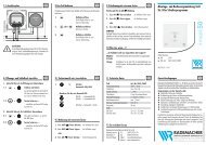
D Montage- und Bedienungsanleitung für ABUS Fenster - ELV
D Montage- und Bedienungsanleitung für ABUS Fenster - ELV
D Montage- und Bedienungsanleitung für ABUS Fenster - ELV

You also want an ePaper? Increase the reach of your titles
YUMPU automatically turns print PDFs into web optimized ePapers that Google loves.
Abb./fig./schéma/afb./ill. 4<br />
Abb./fig.<br />
schéma<br />
afb./ill. 6a<br />
Abb./fig.<br />
schéma<br />
afb./ill. 6b<br />
Riegelbolzen<br />
Locking bolt<br />
Pêne de verrouillage<br />
Vergrendelingspen<br />
Perno del chiavistello<br />
Abb./fig./schéma/afb./ill. 9<br />
D<br />
D<br />
D<br />
Rahmenleiste<br />
Frame strip<br />
Platine de fixation<br />
Kozijnlijst<br />
Listello del telaio<br />
Abb./fig.<br />
schéma<br />
afb./ill. 6c<br />
C<br />
<strong>ABUS</strong> - Das gute Gefühl der Sicherheit<br />
Abb./fig./schéma/afb./ill. 5<br />
Abb./fig./schéma/afb./ill. 7 Abb./fig./schéma/afb./ill. 8<br />
Abb./fig./schéma/afb./ill. 10<br />
D Technische Änderungen vorbehalten. Für Irrtümer <strong>und</strong> Druckfehler keine Haftung. <strong>ABUS</strong> © 2011<br />
G Subject to technical alterations. No liability for mistakes and printing errors. <strong>ABUS</strong> © 2011<br />
B<br />
A<br />
B<br />
(x)<br />
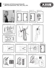
D V. <strong>Montage</strong>anleitung:<br />
Wichtige Hinweise:<br />
1. Vor der <strong>Montage</strong> prüfen Sie bitte die Einstellung des <strong>Fenster</strong>s.<br />
Stellen Sie sicher, dass sich das <strong>Fenster</strong>/die <strong>Fenster</strong>tür einwandfrei<br />
öffnen <strong>und</strong> schließen lässt.<br />
2. Messen Sie auch nach, ob die in Abb. 1a+b angegebenen Maße<br />
an Ihrem <strong>Fenster</strong>/Ihrer <strong>Fenster</strong>tür vorhanden sind.<br />
3. Die Bohrlochtiefen bzw. die Schraubenlängen müssen auf die<br />
örtlichen Gegebenheiten abgestimmt werden, ebenso die empfohlene<br />
Schrägverschraubung bei Holzfenstern.<br />
4. Austreten des Bohrers bzw. der Schrauben auf der Rückseite<br />
vermeiden! Ggf. mit Bohranschlag arbeiten oder die vorhandenen<br />
Schrauben kürzen. Beim Bohren keine beweglichen Teile, Dichtungen<br />
oder Glasscheiben verletzen.<br />
<strong>Montage</strong>:<br />
Falls die Flügelhaube (8) <strong>und</strong> Rahmenhaube (9) montiert sind,<br />
diese zunächst vorsichtig abnehmen.<br />
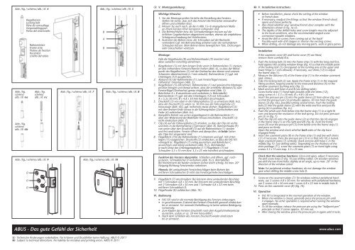
1. Riegelbolzen (5) mit dem langen Ende voran in Rahmenleiste (1) stecken,<br />
an das vorhandene <strong>Fenster</strong>scharnier halten (Abb. 4), so dass der Mittelpunkt<br />
des Riegelbolzens (5) mit der Drehachse des oberen <strong>und</strong> unteren<br />
Scharniers übereinstimmt (± 1 mm erlaubt). Rahmenleiste (1) ggf. mit<br />
Unterlagen (12) ausgleichen.<br />
2. Abstand (X) der Rahmenleiste (1) zum <strong>Fenster</strong>flügel messen;<br />
Hilfsmittel: Unterlagen (Abb. 5).<br />
3. Riegelbolzen (5) entnehmen. Rahmenleiste (1) auf gewünschte <strong>Montage</strong>position<br />
bringen <strong>und</strong> darauf achten, dass der ermittelte Abstand (X) zum<br />
<strong>Fenster</strong>flügel (Drehachse) genau eingehalten wird (Abb. 5).<br />
4. Bohrlöcher A + B anzeichnen <strong>und</strong> vorbohren (s. Bohrtabelle).<br />
Rahmenleiste (1) ggf. mit den Unterlagen (12) mit Schrauben<br />
A = 5,5x 50 mm, B = 4,8 x 50 mm handfest anschrauben.<br />
5. Druckstift (3) von oben in die Führungshülse (2) so einsetzen (Abb. 6a),<br />
dass der Druckstift (3) unten ca. 30 mm aus der Führungshülse (2)<br />
herausragt (Abb. 6b), ggf. mehrmals etwas drehen. Riegelbolzen (5)<br />
mit dem breiten Ende voraus in die Führungshülse (2)einschieben <strong>und</strong><br />
Feder (6) aufstecken (Abb. 6c).<br />
6. Komplette Einheit von unten enganliegend in die Rahmenleiste (1)<br />
über den Widerstand der Blattfeder hinaus einschieben. Druckstift (3)<br />
nicht eindrücken (Abb. 7).<br />
7. Clip (4) auf die Führungshülse (2) drücken, so dass der Clip (4) rechts<br />
<strong>und</strong> links in die Rahmenleiste (1)einrastet (Abb. 8). Rahmenhaube (9)<br />
von unten über den Druckstift (3) auf die Rahmenleiste (1) stecken<br />
<strong>und</strong> fest andrücken. <strong>Fenster</strong> öffnen <strong>und</strong> überprüfen, ob beide Seiten<br />
des Clips fest eingerastet sind.<br />
8. Flügelblech (7)in die Rahmenleiste (1) einsetzen <strong>und</strong> ggf. mit Unterlagen<br />
(11) ausgleichen. Druckstift (3) eindrücken, so dass die FAS 101<br />
verriegelt ist. Flügelblech (7) mittig ausrichten <strong>und</strong> Bohrlöcher C<br />
anzeichnen <strong>und</strong> mittig vorbohren (Abb. 9) (s. Bohrtabelle).<br />
Je nach Dicke des Unterlagenpaketes (11) Flügelblech (7) mit<br />
Schrauben 3,5 x 13 mm bzw. 3,5 x 25 mm handfest anschrauben.<br />
Funktion des <strong>Fenster</strong>s überprüfen. Schließen <strong>und</strong> öffnen, ggf. nachjustieren.<br />
Schraublöcher D vorbohren (Abb. 9) (s. Bohrtabelle).<br />
Bei Holzfenstern die beiden vorderen Löcher leicht schräg, bis max. 20°<br />
Neigung Richtung <strong>Fenster</strong>mitte vorbohren.<br />
Hinweis: Bei umlaufenden <strong>Fenster</strong>beschlägen beim Bohren des<br />
mittleren Schraubloches D nicht das <strong>Fenster</strong>getriebe beschädigen.<br />
9. Flügelblech (7) anschrauben: Bei <strong>Fenster</strong>n ohne umlaufenden Beschlag<br />
mit 3 Schrauben 4,8 x 50 mm. Bei <strong>Fenster</strong>n mit umlaufendem Beschlag<br />
mit 2 Schrauben 4,8 x 50 mm <strong>und</strong> 1 Schraube 4,8 x 22 mm beim<br />
mittleren Schraubloch D.<br />
10. Flügelhaube (8) aufdrücken (Abb. 10).<br />
VI. Bedienung<br />
• FAS 101 wird in die normale Betätigung des <strong>Fenster</strong>s einbezogen.<br />
• In geschlossenem Zustand des <strong>Fenster</strong>s Druckstift generell eindrücken<br />
bis er einrastet. Für normale Drehöffnung ist keine weitere Betätigung<br />
notwendig.<br />
• Zum Kippen des <strong>Fenster</strong>s Druckstift nach dem Kugelschreiberprinzip<br />
ausrasten, sodass er ca. 30 mm herausfährt.<br />
• Nach dem Schließen des <strong>Fenster</strong>s Druckstift wieder eindrücken<br />
bis er einrastet.<br />
G V. Installation instructions:<br />
• Before installation, please check the setting of the window<br />
or French door.<br />
• If necessary, readjust the fittings so that the window (French door)<br />
opens and closes perfectly.<br />
• Also check whether your window/French door complies with the<br />
dimensions shown in fig. 1a+b.<br />
• The depths of the drilled holes and screw lengths must be adjusted<br />
to the local conditions, also the recommended angled screw<br />
connection wooden windows.<br />
• Avoid the drill or screws from coming out at the back!<br />
Possibly work with drill stopper or shorten the existing screws.<br />
• When drilling, do not damage any moving parts, seals or glass panes.<br />
Installation:<br />
If the casement cover (8) and frame cover (9) are fitted,<br />
remove them carefully first.<br />
1. Push the locking bolt (5) into the frame strip (1) with the long end first,<br />
hold against the existing window hinge (fig. 4) so that the middle point<br />
of the locking bolt (5) corresponds to the turning axis of the upper and<br />
lower hinge (± 1 mm allowed). If necessary, use shims (12) to adjust<br />
the frame strip (1).<br />
2. Measure the distance (X) of the frame strip (1) to the window casement<br />
(aid: shims).<br />
3. Take the locking bolt (5) out. Apply the frame strip (1) in the required<br />
fitting position, keeping exactly to the measured distance (X) to the<br />
window casement (turning axis) (fig. 5).<br />
4. Mark and pre-drill holes A and B (see drilling table).<br />
Screw frame strip (1) hand tight possibly with the shims (12),<br />
using screws A = 5.5 x 50 mm, B = 4.8 x 50 mm.<br />
5. Insert the pressure pin (3) into the guide sleeve (2) from above (fig. 6a)<br />
so that the pressure pin (3) protrudes approx. 30 mm from the guide<br />
sleeve (2) (fig. 6b), possibly turning several times. Push the locking<br />
bolt (5) into the guide sleeve (2) with the wide end first and put the<br />
spring (6) in position (fig. 6c).<br />
6. Push the whole unit from below into the frame strip (1) in a tight fit<br />
over and beyond the resistance of the leaf spring. Do not press pressure<br />
pin (3) in (fig. 7).<br />
7. Push the clip (4) onto the guide sleeve (2) so that the clip (4) engages<br />
in the frame strip (1) on the right and left (fig. 8). Push the frame<br />
cover (9) over the pressure pin (3) from below onto the frame strip (1)<br />
and press on firmly.<br />
Open the window and check whether both sides of the clip have<br />
engaged firmly.<br />
8. Insert the casement plate (8) in the frame strip (1) and line with shims<br />
(11) if necessary. Press the pressure pin (3) in so that FAS 101 is locked.<br />
Align casement plate (7) centrally; mark and pre-drill holes C in the<br />
middle (fig. 9): (see drilling table). Depending on the thickness of the<br />
shim package (11), screw the casement plate (7) on hand tight using<br />
screws 3.5 x 13 mm resp. 3.5 x 25 mm.<br />
Check that the window functions: Close and open, adjust if necessary.<br />
Pre-drill screw holes D (fig. 9) (see drilling table). On wooden windows<br />
pre-drill the two front holes slightly at an angle, up to max. 20° in the<br />
direction of the window center<br />
Note: For peripheral window hardware, do not damage the window<br />
gear when drilling the middle screw hole D.<br />
9. Screw on the casement plate (7): for windows without peripheral hardware,<br />
use 3 screws 4.8 x 50 mm. For windows with peripheral hardware,<br />
use 2 screws 4.8 x 50 mm and 1 screw 4.8 x 22 mm in middle hole D.<br />
10. Press on the casement cover (8) (fig. 10).<br />
VI. Operation<br />
• FAS 101 is integrated in the normal operation of the window.<br />
• When the window is closed, generally press the pressure pin until<br />
it engages. No other operation is required when turning the window<br />
open normally.<br />
• To tilt the window, release the pressure pin using the “ballpoint pen”<br />
principle so that it comes approx. 30 mm out.<br />
• After closing the window, press the pressure pin in again until it locks.<br />
www.abus.com